The items listed below are all included in TRD's ... - Fluidraulics Inc
The items listed below are all included in TRD's ... - Fluidraulics Inc
The items listed below are all included in TRD's ... - Fluidraulics Inc

Create successful ePaper yourself
Turn your PDF publications into a flip-book with our unique Google optimized e-Paper software.
Rod Clevis, P<strong>in</strong>s,<br />
& Mounts<br />
Alignment Couplers<br />
Flow Controls<br />
TRD Magnetic Switches<br />
B<strong>all</strong>uff Induction<br />
Switches<br />
Accessories<br />
Technical Data<br />
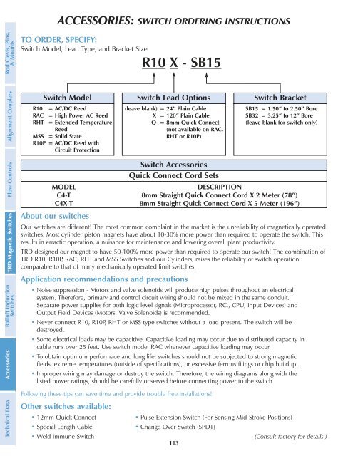
ACCESSORIES: SWITCH ORDERING INSTRUCTIONS<br />
TO ORDER, SPECIFY:<br />
Switch Model, Lead Type, and Bracket Size<br />
Switch Model<br />
R10 = AC/DC Reed<br />
RAC = High Power AC Reed<br />
RHT = Extended Temperature<br />
Reed<br />
MSS = Solid State<br />
R10P = AC/DC Reed with<br />
Circuit Protection<br />
About our switches<br />
Our switches <strong>are</strong> different! <strong>The</strong> most common compla<strong>in</strong>t <strong>in</strong> the market is the unreliability of magnetic<strong>all</strong>y operated<br />
switches. Most cyl<strong>in</strong>der piston magnets have about 10-30% more power than required to operate the switch. This<br />
results <strong>in</strong> erractic operation, a nuisance for ma<strong>in</strong>tenance and lower<strong>in</strong>g over<strong>all</strong> plant productivity.<br />
TRD designed our magnet to have 50-100% more power than required to operate our switch! <strong>The</strong> comb<strong>in</strong>ation of<br />
TRD R10, R10P, RAC, RHT and MSS Switches and our Cyl<strong>in</strong>ders, raises the reliability of switch operation<br />
comparable to that of many mechanic<strong>all</strong>y operated limit switches.<br />
Application recommendations and precautions<br />
• Noise suppression - Motors and valve solenoids will produce high pulses throughout an electrical<br />
system. <strong>The</strong>refore, primary and control circuit wir<strong>in</strong>g should not be mixed <strong>in</strong> the same conduit.<br />
Separate power supplies for both logic level signals (Microprocessor, P.C., CPU, Input Devices) and<br />
Output Field Devices (Motors, Valve Solenoids) is recommended.<br />
• Never connect R10, R10P, RHT or MSS type switches without a load present. <strong>The</strong> switch will be<br />
destroyed.<br />
• Some electrical loads may be capacitive. Capacitive load<strong>in</strong>g may occur due to distributed capacity <strong>in</strong><br />
cable runs over 25 feet. Use switch model RAC whenever capacitive load<strong>in</strong>g may occur.<br />
• To obta<strong>in</strong> optimum performace and long life, switches should not be subjected to strong magnetic<br />
fields, extreme temperatures (outside of specifications), or excessive ferrous fil<strong>in</strong>gs or chip buildup.<br />
• Improper wir<strong>in</strong>g may damage or destroy the switch. <strong>The</strong>refore, the wir<strong>in</strong>g diagrams along with the<br />
<strong>listed</strong> power rat<strong>in</strong>gs, should be c<strong>are</strong>fully observed before connect<strong>in</strong>g power to the switch.<br />
Follow<strong>in</strong>g these tips can save time and provide trouble free <strong>in</strong>st<strong>all</strong>ations!<br />
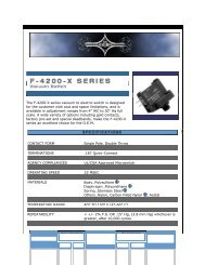
Other switches available:<br />
R10 X - SB15<br />
Switch Lead Options<br />
(leave blank) = 24” Pla<strong>in</strong> Cable<br />
X = 120” Pla<strong>in</strong> Cable<br />
Q = 8mm Quick Connect<br />
(not available on RAC,<br />
RHT or R10P)<br />
Switch Bracket<br />
SB15 = 1.50” to 2.50” Bore<br />
SB32 = 3.25” to 12” Bore<br />
(leave blank for switch only)<br />
Switch Accessories<br />
Quick Connect Cord Sets<br />
MODEL DESCRIPTION<br />
C4-T 8mm Straight Quick Connect Cord X 2 Meter (78”)<br />
C4X-T 8mm Straight Quick Connect Cord X 5 Meter (196”)<br />
• 12mm Quick Connect • Pulse Extension Switch (For Sens<strong>in</strong>g Mid-Stroke Positions)<br />
• Special Length Cable • Change Over Switch (SPDT)<br />
• Weld Immune Switch (Consult factory for details.)<br />
113