The items listed below are all included in TRD's ... - Fluidraulics Inc
The items listed below are all included in TRD's ... - Fluidraulics Inc
The items listed below are all included in TRD's ... - Fluidraulics Inc

You also want an ePaper? Increase the reach of your titles
YUMPU automatically turns print PDFs into web optimized ePapers that Google loves.
BASIC OPTIONS<br />
H C LH LC ELH ELC Cushions<br />
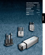
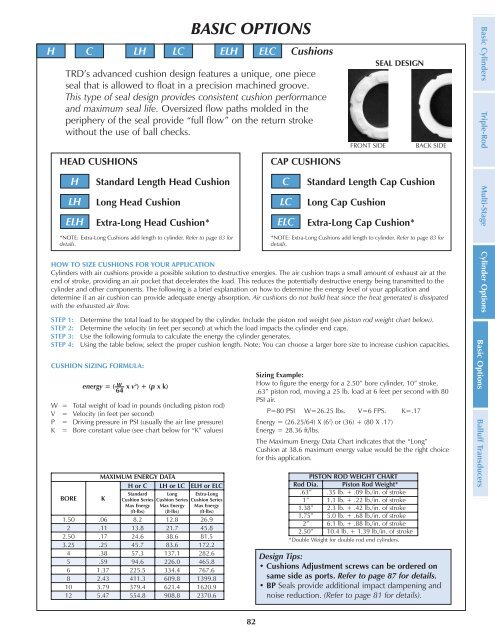
TRD’s advanced cushion design features a unique, one piece<br />
seal that is <strong>all</strong>owed to float <strong>in</strong> a precision mach<strong>in</strong>ed groove.<br />
This type of seal design provides consistent cushion performance<br />
and maximum seal life. Oversized flow paths molded <strong>in</strong> the<br />
periphery of the seal provide “full flow” on the return stroke<br />
without the use of b<strong>all</strong> checks.<br />
HEAD CUSHIONS<br />
H<br />
LH<br />
ELH<br />
Standard Length Head Cushion<br />
Long Head Cushion<br />
Extra-Long Head Cushion*<br />
*NOTE: Extra-Long Cushions add length to cyl<strong>in</strong>der. Refer to page 83 for<br />
details.<br />
82<br />
CAP CUSHIONS<br />
C<br />
LC<br />
ELC<br />
SEAL DESIGN<br />
FRONT SIDE BACK SIDE<br />
Standard Length Cap Cushion<br />
Long Cap Cushion<br />
Extra-Long Cap Cushion*<br />
*NOTE: Extra-Long Cushions add length to cyl<strong>in</strong>der. Refer to page 83 for<br />
details.<br />
HOW TO SIZE CUSHIONS FOR YOUR APPLICATION<br />
Cyl<strong>in</strong>ders with air cushions provide a possible solution to destructive energies. <strong>The</strong> air cushion traps a sm<strong>all</strong> amount of exhaust air at the<br />
end of stroke, provid<strong>in</strong>g an air pocket that decelerates the load. This reduces the potenti<strong>all</strong>y destructive energy be<strong>in</strong>g transmitted to the<br />
cyl<strong>in</strong>der and other components. <strong>The</strong> follow<strong>in</strong>g is a brief explanation on how to determ<strong>in</strong>e the energy level of your application and<br />
determ<strong>in</strong>e if an air cushion can provide adequate energy absorption. Air cushions do not build heat s<strong>in</strong>ce the heat generated is dissipated<br />
with the exhausted air flow.<br />
STEP 1: Determ<strong>in</strong>e the total load to be stopped by the cyl<strong>in</strong>der. <strong>Inc</strong>lude the piston rod weight (see piston rod weight chart <strong>below</strong>).<br />
STEP 2: Determ<strong>in</strong>e the velocity (<strong>in</strong> feet per second) at which the load impacts the cyl<strong>in</strong>der end caps.<br />
STEP 3: Use the follow<strong>in</strong>g formula to calculate the energy the cyl<strong>in</strong>der generates.<br />
STEP 4: Us<strong>in</strong>g the table <strong>below</strong>, select the proper cushion length. Note: You can choose a larger bore size to <strong>in</strong>crease cushion capacities.<br />
CUSHION SIZING FORMULA:<br />
energy = ( w x v 2 ) + (p x k)<br />
64<br />
W = Total weight of load <strong>in</strong> pounds (<strong>in</strong>clud<strong>in</strong>g piston rod)<br />
V = Velocity (<strong>in</strong> feet per second)<br />
P = Driv<strong>in</strong>g pressure <strong>in</strong> PSI (usu<strong>all</strong>y the air l<strong>in</strong>e pressure)<br />
K = Bore constant value (see chart <strong>below</strong> for “K” values)<br />
MAXIMUM ENERGY DATA<br />
H or C LH or LC ELH or ELC<br />
BORE K<br />
Standard Long Extra-Long<br />
Cushion Series Cushion Series Cushion Series<br />
Max Energy Max Energy Max Energy<br />
(ft-lbs) (ft-lbs) (ft-lbs)<br />
1.50 .06 8.2 12.8 26.9<br />
2 .11 13.8 21.7 45.8<br />
2.50 .17 24.6 38.6 81.5<br />
3.25 .25 45.7 83.6 172.2<br />
4 .38 57.3 137.1 282.6<br />
5 .59 94.6 226.0 465.8<br />
6 1.37 225.5 334.4 767.6<br />
8 2.43 411.3 609.8 1399.8<br />
10 3.79 379.4 621.4 1620.9<br />
12 5.47 554.8 908.8 2370.6<br />
Siz<strong>in</strong>g Example:<br />
How to figure the energy for a 2.50” bore cyl<strong>in</strong>der, 10” stroke,<br />
.63” piston rod, mov<strong>in</strong>g a 25 lb. load at 6 feet per second with 80<br />
PSI air.<br />
P=80 PSI W=26.25 lbs. V=6 FPS. K=.17<br />
Energy = (26.25/64) X (62 ) or (36) + (80 X .17)<br />
Energy = 28.36 ft/lbs.<br />
<strong>The</strong> Maximum Energy Data Chart <strong>in</strong>dicates that the “Long”<br />
Cushion at 38.6 maximum energy value would be the right choice<br />
for this application.<br />
PISTON ROD WEIGHT CHART<br />
Rod Dia. Piston Rod Weight*<br />
.63” .35 lb. + .09 lb./<strong>in</strong>. of stroke<br />
1” 1.1 lb. + .22 lb./<strong>in</strong>. of stroke<br />
1.38” 2.3 lb. + .42 lb./<strong>in</strong>. of stroke<br />
1.75” 5.0 lb. + .68 lb./<strong>in</strong>. of stroke<br />
2” 6.1 lb. + .88 lb./<strong>in</strong>. of stroke<br />
2.50” 10.4 lb. + 1.39 lb./<strong>in</strong>. of stroke<br />
*Double Weight for double rod end cyl<strong>in</strong>ders.<br />
Design Tips:<br />
• Cushions Adjustment screws can be ordered on<br />
same side as ports. Refer to page 87 for details.<br />
• BP Seals provide additional impact dampen<strong>in</strong>g and<br />
noise reduction. (Refer to page 81 for details).<br />
Basic Options B<strong>all</strong>uff Transducers<br />
Basic Cyl<strong>in</strong>ders Triple-Rod Multi-Stage Cyl<strong>in</strong>der Options