The items listed below are all included in TRD's ... - Fluidraulics Inc
The items listed below are all included in TRD's ... - Fluidraulics Inc
The items listed below are all included in TRD's ... - Fluidraulics Inc

Create successful ePaper yourself
Turn your PDF publications into a flip-book with our unique Google optimized e-Paper software.
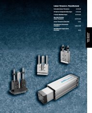
Rod Clevis, P<strong>in</strong>s,<br />
& Mounts<br />
Alignment Couplers<br />
Flow Controls<br />
TRD Magnetic Switches<br />
B<strong>all</strong>uff Induction<br />
Switches<br />
Accessories<br />
Technical Data<br />
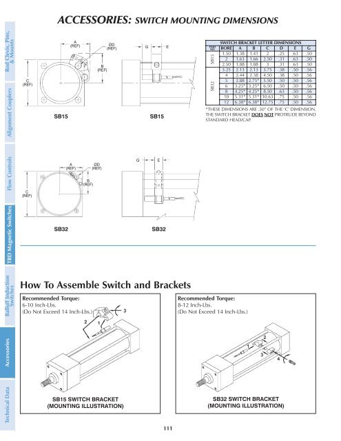
ACCESSORIES: SWITCH MOUNTING DIMENSIONS<br />
How To Assemble Switch and Brackets<br />
Recommended Torque:<br />
6-10 <strong>Inc</strong>h-Lbs.<br />
(Do Not Exceed 14 <strong>Inc</strong>h-Lbs.)<br />
111<br />
SWITCH BRACKET LETTER DIMENSIONS<br />
PART<br />
NO. BORE A B C D E G<br />
1.50 1.38 1.41 2 .25 .63 .50<br />
2 1.63 1.66 2.50 .31 .63 .50<br />
SB15<br />
SB32<br />
Recommended Torque:<br />
8-12 <strong>Inc</strong>h-Lbs.<br />
(Do Not Exceed 14 <strong>Inc</strong>h-Lbs.)<br />
2.50 1.88 1.88 3 .31 .63 .50<br />
3.25 2.13 2.13 3.75 .38 .50 .56<br />
4 2.44 2.38 4.50 .38 .50 .56<br />
5 2.88 2.75* 5.50 .50 .50 .56<br />
6 3.25* 3.25* 6.50 .50 .50 .56<br />
8 4.25* 4.25* 8.50 .63 .50 .56<br />
10 5.31* 5.31* 10.63 .75 .50 .56<br />
12 6.38* 6.38* 12.75 .75 .50 .56<br />
*THESE DIMENSIONS ARE .50” OF THE ‘C’ DIMENSION.<br />
THE SWITCH BRACKET DOES NOT PROTRUDE BEYOND<br />
STANDARD HEAD/CAP.