Chapter 9 - Goodheart-Willcox
Chapter 9 - Goodheart-Willcox
Chapter 9 - Goodheart-Willcox

Create successful ePaper yourself
Turn your PDF publications into a flip-book with our unique Google optimized e-Paper software.
This sample chapter is for review purposes only. Copyright © The <strong>Goodheart</strong>-<strong>Willcox</strong> Co., Inc. All rights reserved.<br />
Learning Objectives<br />
After studying this chapter, you will be able to:<br />
■ Explain how and why text is formatted for<br />
import into a page composition program.<br />
■ Cite the differences and explain the advantages<br />
of bitmap and vector graphics.<br />
■ Define the basic functions of raster image<br />
processors and imagesetters.<br />
■ Explain the functions of page description<br />
languages.<br />
■ Explain file compression and list its<br />
applications.<br />
■ List the most commonly used file formats<br />
and their applications.<br />
■ List the types of internal and external storage<br />
devices along with their advantages and<br />
disadvantages.<br />
■ Define preflighting and explain its importance<br />
to prepress production.<br />
■ Explain the importance of font formats and<br />
font management.<br />
■ Define digital printing and list its advantages<br />
and limitations as well as the various types of<br />
technology used.<br />
Important Terms<br />
cross-platform<br />
bitmap<br />
vector graphics<br />
raster image processor<br />
(RIP)<br />
imagesetter<br />
COMMUNICATION<br />
COMMUNICATION<br />
COMMUNICATION<br />
GRAPHIC<br />
page description<br />
language (PDL)<br />
lossy compression<br />
lossless compression<br />
preflighting<br />
computer-to-plate (CTP)<br />
Electronic Prepress<br />
9<br />
and Digital Printing<br />
Digital systems have penetrated every stage of<br />
the printing process—from the author’s manuscript<br />
to platemaking and running the press. Maintaining<br />
a smooth workflow requires the consistency of<br />
digital data throughout the production process.<br />
Sustaining consistency as well as compatibility<br />
requires that everyone involved in the production<br />
process have an understanding of electronic media.<br />
In a perfect world, every piece of electronic<br />
equipment, as well as every computer program,<br />
would be compatible. Unfortunately, this isn’t the<br />
case. For this reason, many organizations such as<br />
the American National Standards Institute (ANSI),<br />
the International Standards Organization (ISO),<br />
and the Joint Photographic Experts Group (JPEG)<br />
have created standards by which electronic media<br />
and equipment must operate in order to be compatible.<br />
Due to the amount of information and the vast<br />
number of products available, this chapter covers<br />
the most general of information that applies to<br />
different platforms and software.<br />
Computer Platforms<br />
The platform of an electronic imaging system<br />
is the computer system, or hardware, that is used<br />
to operate the software. Software is the computer<br />
program, or instructions, that initiate the functions<br />
of a computer. Among these functions are<br />
word processing, page composition, and drawing<br />
creation. Computer platforms include the elements<br />
necessary to create, assemble, and output<br />
data in the form of type or finished pages, Figure<br />
9-1. The major platforms are the PC (based on the<br />
IBM personal computer), the Apple Macintosh,<br />
and the UNIX system. The platform defines the<br />
173<br />
174 Graphic Communications<br />
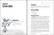
Figure 9-1. Desktop publishing allows graphic designers<br />
to create and edit both text and art. (Xyvision, Inc.)<br />
standard around which a system can be developed.<br />
Once the platform has been defined, software<br />
developers can design and produce different software.<br />
The term cross-platform refers to applications,<br />
formats, or devices that work on different platforms.<br />
For example, a cross-platform programming<br />
environment would enable a programmer to<br />
develop programs for different platforms at the<br />
same time. This is the concept behind the Common<br />
Hardware Reference Platform (CHRP). CHRP is a<br />
prototype system that allows users to run software<br />
written for either the Macintosh or PC platforms. It<br />
also makes possible the connection of peripheral<br />
devices, such as printers, originally designed for<br />
either platform.<br />
Content Creation<br />
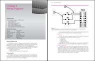
In page composition, text is the body matter.<br />
The graphic images are the artwork and may<br />
consist of line drawings, photographs, charts, and<br />
graphs, Figure 9-2. Text files arecreated in word<br />
processing programs. Even though many word<br />
processors are capable of providing both text and<br />
graphics formatting, it is better to use the word<br />
processor strictly for text entry and editing. This is<br />
Head<br />
Body<br />
copy<br />
Title Type<br />
Background<br />
color<br />
Graphic<br />
image-chart<br />
created in<br />
draw program<br />
Image-digital<br />
photograph<br />
Figure 9-2. Many elements can be used in page composition<br />
including photographs, charts, background color,<br />
body copy, and specialized type styles.<br />
particularly true if the publication will require<br />
extensive text formatting and numerous graphic<br />
elements.<br />
Word processing programs allow the user to<br />
assign codes and formats to text. When you format<br />
text, you assign font type, alignment, margins, line<br />
spacing, numbering, and other properties. The user<br />
identifies specific attributes, such as headlines,<br />
subheads, or body text. These formats are called<br />
styles or tags.<br />
When the text is imported into a page composition<br />
program, the formats are recognized by name<br />
and specific attributes are assigned to that copy. The<br />
styles or attributes usually have been chosen before<br />
page composition is begun. For example, the<br />
publisher may decide that all Heading 1 styles will<br />
be blue, 14-point Helvetica bold, and all body text<br />
will be black 12-point Times New Roman.<br />
Style names must be assigned consistently. Even<br />
though the author uses a different font size or type,<br />
if the proper style names are applied, the production<br />
department’s attributes will override the<br />
author’s style attributes.<br />
Files that have been formatted with a word<br />
processor must be stored and transmitted as binary<br />
files to preserve the formatting.<br />
Most word processing programs allow the user<br />
to save text files as ASCII files. (ASCII stands for the<br />
American Standard Code for Information Interchange.)<br />
An ASCII file is a text file that contains no<br />
special formatting. Each byte in an ASCII file
epresents one character according to the ASCII<br />
code. The ASCII code represents English characters<br />
as numbers, with each assigned a number from zero<br />
to 127.<br />
Although formatting is lost when a file is saved<br />
as an ASCII file, the text can still be repurposed.<br />
Repurposing is reusing content intended for one<br />
medium by reformatting it for another. Most computers<br />
use ASCII codes to represent text so it is possible<br />
to transfer data from one computer to another.<br />
It is important to maintain your original text<br />
and image files. You should make copies and work<br />
from the copies. If data is lost or destroyed during<br />
prepress production and you need to recreate your<br />
work, or if you need to drastically resize or modify<br />
graphics, you will be able to do so.<br />
Creating computer images<br />
Graphic images can be created and saved in a<br />
variety of ways. Digital images can be created<br />
through paint programs, draw programs, digital<br />
photography, and electronic scanning, Figure 9-3.<br />
The electronic images created are saved as one of<br />
many formats. File formats of the graphics are very<br />
important because they determine how much<br />
manipulation can be done to the image and how<br />
well it will be reproduced. (Paint and draw<br />
programs are discussed in the following sections.<br />
Digital camera and electronic scanner operation are<br />
covered in detail in <strong>Chapter</strong> 10.)<br />
Figure 9-3. Flatbed scanners can be used to capture<br />
images from many different types of originals. Scanners<br />
vary in size, capabilities, and method of operation.<br />
(FUJI Photo Film U.S.A., Inc.)<br />
<strong>Chapter</strong> 9 Electronic Prepress and Digital Printing 175<br />
Paint programs<br />
Paint programs allow the user to create freehand<br />
drawings. The images are stored as bitmaps,<br />
or raster graphics, and can be edited easily. Bitmap<br />
images use a grid of small squares (pixels) to<br />
represent graphics. The bitmap image is represented<br />
as rows and columns of dots on this grid.<br />
The value of each dot is stored in one or more bits<br />
of data. Each pixel is encoded as a single binary<br />
digit. For simple black and white images, one bit is<br />
sufficient to represent each dot. However, for colors<br />
and shades of gray, each dot may require anywhere<br />
from 8 to 32 bits of information. The more bits that<br />
are used to represent a dot, the more colors and<br />
shades of gray can be represented.<br />
When using a paint program, the user can see<br />
the rows and columns of dots that compose the<br />
image by zooming in on any given area, Figure 9-4.<br />
The user is able to add or delete color by filling in or<br />
“emptying” each square on the grid. In other words,<br />
when you work with bitmap images, you edit<br />
pixels rather than objects or shapes. Through<br />
these actions, the user is able to modify the image<br />
size, shape, or colors. When bitmaps are enlarged<br />
or reduced, the edges become ragged because they<br />
are composed of “squares” that do not create a<br />
smooth line. This process is referred to as aliasing,<br />
Figure 9-5.<br />
Aliasing is the process by which smooth curves<br />
and other lines become jagged (jaggies) because<br />
the resolution of the graphics device or file is<br />
reduced. Antialiasing is a software technique for<br />
diminishing jaggies. Jaggies are stairstep-like lines<br />
that occur because the output device doesn’t have<br />
high enough resolution to represent a smooth line.<br />
Antialiasing reduces the prominence of jaggies<br />
by surrounding them with intermediate shades of<br />
gray or color. The gray, of course, would be for<br />
gray-scaling devices and the color for color devices.<br />
Although this reduces the jagged appearance of the<br />
lines, it also makes them fuzzier. Many programs<br />
provide an antialiasing option that is extremely<br />
useful when placing text in an image.<br />
Another method for reducing jaggies is called<br />
smoothing. Refer to Figure 9-5. Some printers<br />
change the size and horizontal alignment of dots to<br />
make curves smoother. Other printers reduce dot<br />
size of those dots that make up a curved line.<br />
Simple paint programs are usually included on<br />
most personal computers and are adequate for<br />
home use or simple office functions. More advanced<br />
176 Graphic Communications<br />
Marquee……<br />
Lasso……<br />
Airbrush……<br />
Eraser……<br />
Rubber stamp……<br />
Blur……<br />
Pen……<br />
Line……<br />
Paint bucket……<br />
Hand……<br />
Foreground color……<br />
Default colors……<br />
Standard mode……<br />
Standard screen……<br />
mode<br />
……<br />
……Move<br />
……Magic wand<br />
……Paintbrush<br />
……Pencil<br />
……Smudge<br />
……Dodge<br />
……Type<br />
……Gradient<br />
……Eyedropper<br />
……Zoom<br />
……Switch colors<br />
……Background color<br />
……Quick mask mode<br />
……Full screen mode<br />
Full screen mode with menu bar<br />
Figure 9-4. Most paint programs are limited to the basic tools indicated above.<br />
Aliased image<br />
Antialiased image<br />
Figure 9-5. The antialiasing technique helps smooth<br />
jaggies by filling in squares along the edge with color that<br />
varies slightly from that on the image.<br />
paint programs are used professionally for creating<br />
print, electronic, and video images, Figure 9-6.<br />
Many graphic designers also use draw or<br />
illustration/design programs.<br />
Draw programs<br />
Like paint programs, draw programs enable the<br />
user to create, store, and merge images into<br />
documents. Unlike paint programs, draw programs<br />
use vector graphics instead of raster graphics,<br />
Figure 9-7. In computer graphics, a vector is a line<br />
that is defined by its start and end point. With<br />
Figure 9-6. Digitizing tablets, paint pens, and a computer<br />
mouse can be used with most professional paint<br />
programs. (Graphic Paintbox 2 by Quantel)<br />
vector graphics, images are represented as mathematical<br />
formulas that define all the shapes in the<br />
image as well as their placement on a document.<br />
Vector graphics are more flexible than raster graphics<br />
because they look the same even when they are<br />
scaled to different sizes and they can be represented<br />
at any resolution. This makes them ideal for highresolution<br />
output. Vector graphics are also referred<br />
to as object-oriented graphics.
Selected line<br />
Figure 9-7. When a line is selected on a vector image,<br />
the nodes will be visible. The object selected can be<br />
modified by grabbing and dragging the line.<br />
A Bezier curve is a vector graphic named after<br />
French mathematician Pierre Bezier. It is defined<br />
mathematically by two endpoints and two or more<br />
other points that control its shape, Figure 9-8.<br />
Nearly all draw programs support Bezier curves.<br />
The two endpoints of the curve are called anchor<br />
points. The other points, which define the shape of<br />
the curve, are called handles, tangent points, or<br />
nodes. Attached to each handle are two control<br />
points. By moving the handles or the control points,<br />
you can modify the shape of the curve.<br />
Handle<br />
Anchor point<br />
Figure 9-8. By moving the handles or the control points,<br />
you can modify the shape of a Bezier curve.<br />
<strong>Chapter</strong> 9 Electronic Prepress and Digital Printing 177<br />
Manipulating Images<br />
Some graphics editing is possible with paint<br />
and draw programs, but more extensive and precise<br />
changes should be made with an image<br />
manipulation program, or image editor. Some<br />
of the most commonly used image manipulation<br />
programs include Adobe Photoshop,<br />
Macromedia Freehand, CorelDRAW!, and<br />
Adobe Illustrator. The type of program that can<br />
be used will depend on your computer platform<br />
and the image format (vector or bitmap).<br />
Full-featured image editors permit manipulation<br />
of almost any aspect of the image including<br />
cropping, color and contrast, adding or removing<br />
visual information, and even combining images.<br />
See Figure 9-9. As you gain experience with image<br />
manipulation programs, you will be able to<br />
sharpen, blur, and smudge edges; mix, choose, and<br />
apply colors; paint, draw, work with multiple<br />
layers, clone, apply filters, create gradients and<br />
textures, adjust color, and print color separations as<br />
well as composites.<br />
Figure 9-9. When cropping an image in an imaging program<br />
such as Adobe Photoshop, you would use a marquee<br />
tool to make a selection, then trim the image.<br />
Many programs allow the user to restrict<br />
modifications to one area of a picture or to make<br />
picture-wide changes. Additional information on<br />
creating and modifying images is included in<br />
<strong>Chapter</strong>s 10 and 11.<br />
178 Graphic Communications<br />
Raster image processors (RIPs)<br />
In electronic publishing, vector graphics information<br />
is transferred from a design workstation to<br />
a raster image processor (RIP), Figure 9-10. A raster<br />
image processor is a hardware-software combination<br />
that converts all elements of the vector images<br />
into a bitmapped image at the resolution of the<br />
selected output device. Most RIPs have many useful<br />
features and are able to perform multiple functions,<br />
some of which are listed below. Because each device<br />
is unique and supports different applications, the<br />
following list is not all-inclusive.<br />
■ Allows the operator to view screened<br />
files before imaging.<br />
■ Supports many font types, allowing for<br />
quick and easy downloading, proofing,<br />
and listing of fonts.<br />
■ Offers different dot shapes.<br />
■ Can drive multiple output devices<br />
simultaneously.<br />
■ Allows interpretation and output to occur<br />
simultaneously.<br />
■ Interprets color composite files directly<br />
and separates them into CMYK, RGB,<br />
and/or spot colors.<br />
■ Has high-quality screening technology<br />
that reduces or eliminates moiré<br />
patterns.<br />
Figure 9-10. Raster image processors (RIPs) have many<br />
useful features and are able to perform multiple functions<br />
including job management and color composite file interpretation<br />
and separation. (Xitron)<br />
Dot-gain calibration can also be performed by<br />
many RIPs. Dot gain is the optical increase in the<br />
size of a halftone dot during prepress operations or<br />
the mechanical increase in halftone dot size that<br />
occurs as the image is transferred from plate-toblanket-to-paper<br />
in lithography.<br />
The RIP allows different sets of calibration<br />
tables to be selected depending on the parameters,<br />
such as screen ruling and type of printing. By<br />
controlling specific on-press calibrations, throughput<br />
and consistency can be greatly improved. Dot<br />
gain can also be adjusted by individual color<br />
channel and for numerous screen rulings and<br />
resolution combinations.<br />
Imagesetters<br />
The RIP interprets the page composition information<br />
for the marking engine of the imagesetter,<br />
Figure 9-11. The imagesetter is a typesetting device<br />
used to output fully-paginated text and graphic<br />
images at a high resolution onto photographic film,<br />
paper, or plates. Figure 9-12 compares output<br />
results from an ink-jet printer, a laser printer, and an<br />
imagesetter. Output problems are likely to occur<br />
during the transmission of files from the RIP to the<br />
imagesetter. It is usually the responsibility of<br />
the imagesetter operator to troubleshoot these<br />
Figure 9-11. With the addition of an add-on device, many<br />
imagesetters are able to create plates as well as film.<br />
(FUJI Photo Film U.S.A., Inc.)
problems. However, if the files have not been<br />
properly prepared, they may need to be returned to<br />
their point of origination.<br />
Using laser technology, the imagesetter outputs<br />
the page or color separations on the selected<br />
medium. To ensure high-quality output, especially<br />
with color separations, special attention must be<br />
given to calibration and maintenance of the<br />
imagesetter. Imagesetters are manufactured by a<br />
number of companies and they differ in speed,<br />
precision, resolution, screening technology, and<br />
media capability.<br />
Page description languages (PDLs)<br />
A page description language (PDL) serves as the<br />
interface between the page composition workstation<br />
and the RIP. PDLs are used in electronic publishing<br />
as a format by which all the elements to be<br />
placed on the page, their respective positions on the<br />
page, and the page’s position within the larger document<br />
are identified in a manner that the output<br />
device can understand.<br />
Several common PDLs are Adobe PostScript,<br />
Adobe portable document format (PDF), and<br />
Hewlett-Packard PCL (Printer Control Language).<br />
PDLs enable imagesetters developed by different<br />
companies to interpret electronic files from any<br />
number of personal computers and software programs.<br />
PostScript, PDF, and PCL are objectoriented,<br />
meaning that they describe a page in terms<br />
of geometrical objects such as lines, arcs, and circles.<br />
<strong>Chapter</strong> 9 Electronic Prepress and Digital Printing 179<br />
Imagesetter Laser printer Ink-jet printer<br />
Figure 9-12. Compare reproduction of the same original image by three different output devices. An imagesetter will<br />
normally produce the most accurate reproduction.<br />
Adobe PostScript<br />
The most common use of Adobe PostScript is to<br />
describe the appearance of a page to an output<br />
device. Output devices use an interpreter to interpret<br />
PostScript files. An interpreter is a computer<br />
program that resides on a controller board in the<br />
printer. The interpreter receives the PostScript page<br />
descriptions and translates them into patterns of<br />
dots for a printer or pixels for a display.<br />
The interpreter allows PostScript files to be used<br />
on various output devices. After receiving a page<br />
description, the interpreter constructs a representation<br />
of the page to suit the output device. For example,<br />
the interpreter can determine whether the<br />
output device is a black-and-white or color printer,<br />
an RGB video monitor, or a 2000 dpi imagesetter.<br />
Once these parameters have been defined, the interpreter<br />
modifies its instructions accordingly.<br />
Since the introduction of the original Adobe<br />
PostScript, PostScript Levels 2 and 3 have been<br />
added. These new levels integrate the original Post-<br />
Script language, all previous language extensions,<br />
and new language features into the core PostScript<br />
language imaging model. The newer interpreters<br />
are not fully compatible with the original.<br />
Portable document format (PDF)<br />
Adobe Portable Document Format (PDF) has<br />
become the standard for electronic document distribution<br />
throughout the world. PDF is a universal file<br />
format that preserves all aspects of a native file<br />
180 Graphic Communications<br />
regardless of the application or platform that uses<br />
the Adobe Acrobat application to create the PDF<br />
file. Anyone using the Adobe Acrobat Reader can<br />
view, navigate, and print the file exactly as the<br />
author intended. The PDF file is the leading electronic<br />
document workflow element in the paradigm<br />
"Create, Distribute, and Print as needed."<br />
In the PDF workflow, the PDF file is used to create<br />
the film or plates needed by the print production<br />
facility. Within that file, all of the necessary information<br />
is contained. The fonts, graphics, images,<br />
text, and document layout are already present — no<br />
further prepress steps remain to be completed by<br />
the production department.<br />
The Acrobat program consists of the applications<br />
Acrobat Distiller, Acrobat Exchange, and<br />
Acrobat Catalog, along with a distributable reader.<br />
See Figure 9-13.<br />
Figure 9-13. Adobe Acrobat simplifies the creation of<br />
PDF files. The Adobe Reader screen capture above illustrates<br />
a pull-down menu, thumbnails of pages in the document,<br />
and a completed page. (Adobe Acrobat)<br />
The Acrobat Distiller is the engine that creates<br />
PDF files. Acrobat Exchange is the segment of PDF<br />
that allows minimal editing, linking, and final formatting,<br />
as well as the ability to create hypertext<br />
links to other portions of the document, to other<br />
PDF files, or to Web sites.<br />
The Acrobat Catalog provides extensive indexing<br />
and searching capabilities. The Catalog searches<br />
through the text of PDF, indexing, referencing, and<br />
cataloging information. This application can be performed<br />
with one PDF, an entire directory, or CD full<br />
of PDF files.<br />
The Adobe Acrobat Reader has now been<br />
extended to the hand-held Palm device (a PDA, or<br />
Personal Digital Assistant), allowing mobile professionals<br />
the flexibility to easily view PDF files. This<br />
gives the PDA user the ability to view visually rich<br />
documents that were previously accessible only on<br />
a desktop or laptop computer. Additionally, these<br />
documents can be secured, so only users with passwords<br />
can view them. This makes possible greater<br />
flexibility in viewing complex documents for "on<br />
the go" professionals, streamlining their business<br />
processes.<br />
Unlike the complex, continuous stream of data<br />
in PostScript files, PDF files are simple, compact,<br />
object-oriented files. They process quickly and are<br />
also page-independent so single pages can be<br />
replaced or altered without reprocessing the other<br />
pages. Page independence also allows printing<br />
pages in any order from a single file. PDF files are<br />
also self-contained. This means the file has all the<br />
fonts and other resources needed to image it.<br />
PostScript was designed with the print industry<br />
in mind. PDF, on the other hand, has been created to<br />
support CD-ROM, Internet and intranet page production,<br />
digital printing technologies, and the 100%<br />
digital workflow requirements of computer-to-plate<br />
technology. An intranet is an internal network<br />
within an organization or institution that is based<br />
on the same network protocols as the Internet.<br />
Rather than redesigning materials, companies often<br />
recycle or repurpose the content of their printed<br />
media. The PDF format was created with repurposing<br />
in mind.<br />
PDF files are also much smaller than comparable<br />
PostScript files so they can be sent quickly across<br />
the Internet or a network for remote proofing or<br />
printing. To save mailing and printing costs, many<br />
government forms are available as PDF files. The<br />
files may be downloaded off the Internet or copied<br />
from compact disks.<br />
The PDF file format allows incorporation of an<br />
extended job ticket. An extended job ticket is an<br />
electronic document that contains all of the instructions<br />
required for processing a job, Figure 9-14. It<br />
includes customer information, proofing directives,<br />
trapping, imposition and ripping parameters, and<br />
even finishing and shipping instructions. The job<br />
ticket specifications can be easily viewed and modified<br />
by everyone who has access to the file.<br />
PDF is almost the ideal preflighting tool. If all<br />
the elements are not present at the time of the cre-
ation of the file, the user is warned. Other key features<br />
and benefits of PDF are the provision of a single<br />
file for viewing, distributing, archiving, editing<br />
and printing small file sizes and the provision of<br />
built-in preview. PDF also has the ability to access<br />
many types of files including EPS, TIFF, PICT,<br />
QuarkXPress, PageMaker, and PostScript from<br />
applications in both Macintosh and PC platforms.<br />
Portable document software typically will save<br />
a document bitmap, the ASCII text, and the font<br />
data. Even with compression, most PDF files are<br />
many times larger than the original file.<br />
<strong>Chapter</strong> 9 Electronic Prepress and Digital Printing 181<br />
Figure 9-14. A job ticket contains several files allowing the operator access to customer information, specific page<br />
data, the type of processes involved, and the type of output. (AGFA)<br />
File compression<br />
Before sending digital data to a service bureau<br />
or printer, most publishers will compress, or reduce,<br />
the size of the files. Some programs automatically<br />
compress when the file is converted and then<br />
decompress when it is viewed. File compression<br />
requires less storage space, and enables easier<br />
data management and quicker transmission by<br />
eliminating the redundancies and other unnecessary<br />
elements from the original. Two common<br />
compression types are lossless compression and<br />
lossy compression.<br />
182 Graphic Communications<br />
Lossless compression refers to data compression<br />
techniques in which no data is lost. The PKZIP<br />
compression technology is an example of lossless<br />
compression. The files are often referred to as<br />
zip files. Decompressing them is called unzipping.<br />
Decompression, simply put, is a reversal of the compression<br />
process. Files that have been compressed<br />
with PKZIP usually end with a .ZIP extension. ZIP<br />
files that end with an .EXE extension are selfextracting<br />
files which can be unzipped simply by<br />
opening the file.<br />
For most types of data, lossless compression<br />
techniques can reduce the space needed by about<br />
50%. Lossless algorithms used for image compression<br />
assume that the likely value of a pixel can be<br />
inferred from the values of surrounding pixels.<br />
Because lossless compression does not discard any<br />
of the data, the decompressed image is identical to<br />
the original.<br />
Other common lossless compression methods<br />
are the Huffman method, Lempel-Ziv-Welch (LZW),<br />
and run-length encoding (RLE). Both the Huffman<br />
and LZW methods of compression are data<br />
compression techniques in which adjacent bits are<br />
replaced with codes of varying lengths. For<br />
example, this technique would encode the fact that<br />
zero occurs 20 times, rather than using 20 zeros.<br />
This information would use 4 bytes instead of 20.<br />
Run-length encoding (RLE) encodes digital data<br />
to reduce the amount of storage needed to hold the<br />
data without any loss of information. Each coded<br />
item consists of a data value and the number of<br />
adjacent pixels with the same data value. (In other<br />
words, strings of the same character are encoded as<br />
a single number.) This is a very efficient way of<br />
encoding large areas of flat color used in linework<br />
and text.<br />
Lossy compression refers to data compression<br />
techniques in which some data is lost. Lossy<br />
compression technologies attempt to eliminate<br />
redundant or unnecessary information. Most video<br />
compression technologies use a lossy compression.<br />
This improves the speed of data transfer but causes<br />
a slight degradation when the image is decompressed<br />
so it can be used.<br />
Lossless compression is preferred for images<br />
that are to be printed because each time a lossy<br />
compression is applied, more information is lost.<br />
The loss of data may not be noticeable on screen but<br />
it will be very noticeable in high-resolution printed<br />
output.<br />
Lossy compression techniques include<br />
quantization, Delta Pulse Code Modification<br />
(DPCM), and JPEG. Quantization is a filtering<br />
process that determines the amount and selection of<br />
data to eliminate so the data can be encoded with<br />
fewer bits. DPCM measures one set of bits and then<br />
measures differences from that set. The differences<br />
are then encoded into fewer bits.<br />
The JPEG file format was created by the Joint<br />
Photographic Experts Group in collaboration with<br />
the International Standards Organization (ISO)<br />
and the Consultative Committee for International<br />
Telegraphy and Telephony (CCITT). The JPEG format<br />
was designed to establish an international data<br />
compression standard for continuous-tone digital<br />
still images. JPEG compression is an open-system,<br />
cross-platform, cross-device standard that can<br />
reduce files to about 5% of their normal size.<br />
JPEG is based on the discrete cosine transform<br />
(DCT) algorithm. The DCT is a lossy compression<br />
algorithm that analyzes each pixel block, identifies<br />
color frequencies, and removes data redundancy.<br />
The JPEG algorithm requires the same processing<br />
amount to compress or decompress an image. JPEG<br />
compression can incorporate other algorithms,<br />
including quantization algorithms and one-dimensional<br />
modified Huffman encoding.<br />
JPEG is a popular standard on the Internet due<br />
to extreme compression and the ability to support<br />
24-bit color. The JPEG file format allows the user to<br />
control the compression ratio and reproduction<br />
quality at the point of compression, Figure 9-15 The<br />
JPEG file format contains bitmap information only<br />
and supports grayscale, RGB, and CMYK color<br />
models.<br />
A major goal of JPEG is to maintain the appearance<br />
of an image rather than the actual data that<br />
constituted the original. This works because we are<br />
visually less sensitive to high-frequency color. JPEG<br />
is a lossy compression and therefore deletes some<br />
image information, but the expanded image<br />
remains visually whole.<br />
JPEG functions best for color and gray-scale<br />
continuous-tone images. Compressing images with<br />
high-contrast edges (line graphics or text) enough<br />
to reduce the file size significantly will adversely<br />
affect the portion containing the text. Selective<br />
compression enables users to specify different<br />
compression levels for different elements within a<br />
single image. EPS color image files embedded in a
Figure 9-15. Encoding options available when saving a<br />
file using the JPEG compression option.<br />
digital document result in a very large file.<br />
EPS-JPEG compression creates files for incorporation<br />
into page composition software that are significantly<br />
smaller than standard EPS files. Images vary<br />
in amount of compressible data without detracting<br />
from visible quality. The user should experiment<br />
with quality settings to determine the maximum<br />
compression usable without perceptibly altering<br />
appearance. Since data is lost in each compression/decompression<br />
cycle, experienced users<br />
recommend using JPEG compression only on final<br />
images, and using it at the maximum quality<br />
setting, Figure 9-16.<br />
Figure 9-16. JPEG compression should be used at maximum<br />
quality to preserve the integrity of the data being<br />
compressed.<br />
<strong>Chapter</strong> 9 Electronic Prepress and Digital Printing 183<br />
File Formats<br />
Many different file formats exist; each type<br />
varies in the way images are saved, how they can be<br />
modified, and how well they will reproduce. File<br />
formats contain a number of important aspects,<br />
including image placement, resolution, color, and<br />
background. The following are some of the most<br />
commonly used formats.<br />
Tagged image file format (TIFF or TIF)<br />
The tagged image file format (TIFF or TIF) is a<br />
raster graphic file used for exchanging bitmapped<br />
images between applications. Depending on the<br />
source application, a TIFF file can allow lossless or<br />
JPEG compression. The format supports bitmap,<br />
grayscale, RGB, CMYK, and indexed color models.<br />
It also allows the inclusion of embedded paths and<br />
alpha channels. TIFF files can be exchanged among<br />
several platforms, including Mac OS, DOS, PC, and<br />
UNIX.<br />
Tagged image file format for image<br />
technology (TIFF/IT-P1)<br />
The tagged image file format for image<br />
technology (TIFF/IT-P1) is a device-dependent<br />
format used for describing four-color documents,<br />
including specifications for printing presses.<br />
TIFF/IT-P1 is a raster-based input format designed<br />
to be used with high-end CEPS (Color Electronic<br />
Prepress Systems). It is favored by the magazine<br />
industry for digital delivery of color advertising<br />
files. The P1 or “profile one” component was added<br />
when the format was accepted by the International<br />
Standards Organization (ISO) for consideration as<br />
an international standard.<br />
TIFF/IT-P1 is designed to reduce the need for<br />
additional time and labor created when CEP<br />
systems cannot communicate easily.<br />
Encapsulated PostScript (EPS)<br />
The Encapsulated PostScript (EPS) is one of the<br />
most stable of the file formats used in outputting to<br />
an imagesetter. It is less convenient than a TIFF but<br />
will usually provide more stable results when output.<br />
EPS provides a very reliable format for graphic<br />
images because it handles both vector and raster<br />
images.<br />
184 Graphic Communications<br />
The EPS format allows inclusion of low-resolution<br />
previews for screen display and nonPostScript<br />
printing. It is also possible to display just a box with<br />
the file name of an image instead of the image itself,<br />
Figure 9-17. The EPS format supports bitmap,<br />
grayscale, RGB, CMYK, spot color, and indexed<br />
color models.<br />
Figure 9-17. Since image files are usually very large and<br />
tend to slow a system down, the EPS file format allows<br />
the user to display just a box with the filename of an<br />
image instead of the image itself.<br />
EPS files also allow the inclusion of open press<br />
interface (OPI) comments and the creation of<br />
embedded paths. The open press interface (OPI) file<br />
format allows the replacement of low-resolution<br />
images in files from one system with high-resolution<br />
image files on another. If saved in ASCII data<br />
format, EPS pictures can be opened and read in a<br />
text editor.<br />
Windows Metafile (WMF) and PICT<br />
The Windows Metafile (WMF) is the<br />
Windows 95/NT version of the PICT file format.<br />
The PICT is a Mac graphics file based on the<br />
original Mac OS QuickDraw drawing routines.<br />
Both the WMF and the PICT format can hold both<br />
bitmapped and object-oriented images. The original<br />
PICT format could only support 8 colors, but a<br />
newer version called PICT2 supports up to<br />
256 colors.<br />
Desktop color separations (DCS 1.0<br />
and DCS 2.0)<br />
The desktop color separations 2.0 (DCS 2.0) file<br />
format is an EPS graphic saved as a single file that<br />
can include up to six plates (cyan, magenta, yellow,<br />
black, and two spot colors) and a master image. The<br />
master file is used for composite printing. The DCS<br />
format supports grayscale, RGB, spot color, and<br />
CMYK color models. DCS files print faster than<br />
standard EPS files and can contain both bitmap and<br />
object-oriented information.<br />
The desktop color separations 1.0 (DCS 1.0)<br />
creates five separate files, one for each process color<br />
(CMYK), and a data or master file. DCS 1.0 is also<br />
referred to as five-file format.<br />
The Photo CD<br />
The Photo CD or proprietary Eastman Kodak<br />
Company format is designed for storing compressed<br />
photographic images on CD-ROM. It can<br />
only contain raster information. The format supports<br />
grayscale, RGB, and CIELAB color models.<br />
The digital images can be viewed on-screen or<br />
retrieved with the proper system.<br />
Graphics interchange format (GIF)<br />
The graphics interchange format (GIF) was<br />
originally designed by CompuServe to transfer<br />
graphic files between computer systems. GIF files<br />
can support only raster images, but can handle up<br />
to 256 colors, and various resolutions. GIF includes<br />
data compression, making it especially effective for<br />
scanned photos and a popular graphics format for<br />
images on the Internet.<br />
Autotracing<br />
Some graphics programs incorporate an<br />
autotracing feature. Autotracing is a process for<br />
converting a raster image into a vector image. Most<br />
autotracing packages read files in a variety of<br />
bitmapped formats (PCX and TIFF are the most<br />
common) and produce a file in a vector format such<br />
as an EPS. The conversion techniques used, and the<br />
accuracy of the conversion process, differ from one<br />
package to another.<br />
File names<br />
File naming conventions are often overlooked<br />
or even ignored. However, carefully naming your<br />
files will help keep your work organized. Whether
you create a standard in-house convention or take<br />
advice from your service bureau, the format must<br />
be applied in a consistent manner.<br />
Computer platforms and programs are subject<br />
to their own conventions. Macintosh file names<br />
should be kept under 20 characters in length, and<br />
although the latest versions of Windows allow file<br />
names to contain up to 255 characters, PC file names<br />
should be limited to less then 20 characters with a<br />
three character extension. In addition to these builtin<br />
limitations, there are several general rules you<br />
should follow.<br />
■ Only alphanumeric characters should be<br />
used. The use of symbols should be<br />
avoided.<br />
■ File names should not begin with a space.<br />
■ Each file name should be unique.<br />
■ The appropriate file extensions should be<br />
used to identify file type, such as .TIFF,<br />
.EPS, or .FPO.<br />
To avoid confusion, revised files should not be<br />
submitted with the same name as the original file.<br />
However, if you are using automatic picture<br />
replacement (APR) or OPI files, it is important that<br />
you do not rename them. The name of the file serves<br />
as the link to the high-resolution image and changing<br />
the name will cause delays while the link is<br />
reestablished.<br />
Internal and External Storage<br />
Devices<br />
Every computer system comes with a certain<br />
amount of physical memory, usually referred to as<br />
main memory or RAM. RAM is the short-term<br />
memory the computer uses to store information in<br />
process. Systems can be updated and memory<br />
capabilities can be increased to support additional<br />
programs. In addition to having a computer system<br />
that is capable of running your programs, you must<br />
have some means for storing and transmitting data.<br />
The term memory identifies data storage that<br />
comes in the form of chips, while the word storage<br />
is used for memory that exists on tapes or disks.<br />
Although compression methods can be used to<br />
reduce file size, most page composition files remain<br />
very large. Fortunately, there are many types of<br />
storage devices available that will accommodate<br />
large files. Storage devices vary in terms of size<br />
(physical and memory), access capabilities, speed,<br />
<strong>Chapter</strong> 9 Electronic Prepress and Digital Printing 185<br />
reusability, and integrity. Storage capacity is<br />
measured in kilobytes (1024 bytes), megabytes<br />
(1024 kilobytes), and gigabytes (1024 megabytes).<br />
Disk storage<br />
There are two basic types of disks, magnetic and<br />
optical. (A disk is a round plate on which data can<br />
be encoded.) Data is encoded as microscopic magnetized<br />
needles on a disk’s surface. You can record<br />
and erase data on a magnetic disk any number of<br />
times, just as you can with a cassette tape used for<br />
recording music. Magnetic disks come in a number<br />
of different forms, including hard and floppy.<br />
The hard disk drive, or hard drive, is a machine<br />
that reads data from and writes data to a hard disk.<br />
Hard disk drives are usually built into the computer<br />
system. The hard disk drive contains one or more<br />
permanent aluminum hard disks coated with a<br />
magnetic material, Figure 9-18. The aluminum<br />
disks are rotated very quickly and a read/write<br />
head moves over the disk surface, which contains<br />
densely packed magnetic tracks. The read/write<br />
head is used to write (record) or read (retrieve)<br />
information as the magnetic tracks spin past the<br />
head.<br />
Storage capacity varies and can be increased by<br />
adding another hard drive, replacing your hard<br />
drive with a higher-capacity one, or using a new<br />
configuration known as RAID (redundant array of<br />
independent disks), Figure 9-19.<br />
Figure 9-18. Storage capacity varies and can be<br />
increased by adding another hard drive or replacing your<br />
hard drive with a higher-capacity one.<br />
186 Graphic Communications<br />
Figure 9-19. RAID storage devices consist of a base<br />
unit, expansion units, and a removable cover. Most configurations<br />
are hot-swappable, allowing the removal and<br />
replacement of failed drives or power supplies without<br />
shutting down the system. (The RAIDinc Cobra LTE,<br />
courtesy of RAID, Inc.)<br />
RAID offers almost unlimited storage capacity.<br />
The RAID configuration connects a number of highcapacity<br />
hard disk drives together to act as a single<br />
huge hard drive. In addition to increased storage<br />
capacity, RAID increases file-access speeds and<br />
data-transfer rates while providing varying degrees<br />
of data protection and failure-proofing the storage<br />
subsystem. RAID continually copies data to each of<br />
its drives so, if and when a drive crashes, it can be<br />
replaced without system downtime or loss of data.<br />
Removable hard disk drives are often referred to<br />
as removable cartridge devices. Removable hard<br />
drives are hard disks encased in a metal or plastic<br />
cartridge so you can remove them just like a floppy<br />
disk. Removable hard disk drives are very fast<br />
(often faster than fixed hard disks) and have a typical<br />
storage capacity ranging from 60 Mb to 250 Mb.<br />
Floppy disk drives function in the same way as<br />
a hard disk drive but they use a removable disk<br />
known as a floppy disk. Floppy disk drives are relatively<br />
slow and have a limited capacity, making<br />
them unsuitable for graphics applications. Floppy<br />
disks, however, are portable, inexpensive, and fairly<br />
reliable for text files. A high-density 3 1/2″ floppy<br />
disk can hold 1.44 Mb of data. Hard disk drives are<br />
from two to 20 times faster than a floppy so it is recommended<br />
that you work from your hard drive<br />
and save to the floppy.<br />
ZIP, JAZ, and SyQuest SparQ disks are essentially<br />
floppy disks with a vast amount of storage<br />
capacity. The disks themselves are, like a floppy<br />
disk, 3 1/2″ in size, but they are twice the thickness<br />
and can typically store more than 100 Mb of<br />
data. Some disks can hold over 1 Gb of data. Special<br />
ZIP, JAZ, and SparQ disk drives are required,<br />
Figure 9-20.<br />
Figure 9-20. ZIP drives are available as external or<br />
internal units.<br />
Unlike floppy and hard disks, which use<br />
electromagnetism to encode data, optical disk<br />
drives use a laser to read and write data. Optical<br />
disks have very large storage capacity but they are<br />
not as fast as hard disks. Five and one-quarter inch<br />
opticals may hold up to 2.3 Gb of digital information<br />
per side while 3 1/2″ opticals hold 230 Mb. The less<br />
expensive optical disk drives are read-only.<br />
Read/write optical disk systems record data by<br />
burning microscopic pits in the surface of the disk<br />
with a laser. To read the disk, another laser beam<br />
shines on the disk and detects the pits by changes in<br />
the reflection pattern. Optical disks have a much<br />
larger data capacity than magnetic disks. Optical<br />
disks come in three forms, CD-ROM, WORM, and<br />
erasable optical.<br />
CD-ROMs are read-only disks, Figure 9-21. You<br />
can read the data from a CD-ROM but you cannot
Figure 9-21. Although CD drives are included with most<br />
computer systems, external units are available.<br />
modify, delete, or write new data. CDs are currently<br />
the most stable storage medium and are therefore<br />
ideal for long-term storage.<br />
WORM (write-once, read many) or CD-R (compact<br />
disc-recordable) disks can be written once and<br />
then read any number of times. However, you need<br />
a special disk drive to write data onto a WORM<br />
disk. This type of media storage is inexpensive and<br />
reliable. However, a number of disks will need to<br />
be disposed of when they are used for backup of<br />
works in progress.<br />
Erasable optical (EO) disks can be read, written<br />
to, and erased just like magnetic disks. EO disks<br />
may be referred to as CD-RWs (compact discrewritable).<br />
The CD-RW disks are ideal for<br />
intermediate backup of works in progress because<br />
they can be erased about 1000 times before their<br />
recording capabilities deteriorate. Many of the<br />
CD-RW disk drives can be used to read CD-ROMs<br />
and are capable of moving two or more megabytes<br />
per second.<br />
Magneto-optical (MO) drives combine magnetic<br />
disk technologies with CD-ROM technologies.<br />
Like magnetic disks, MO disks can be read, written<br />
to, and removed, Figure 9-22. However, their storage<br />
capacity can be more than 200 megabytes. In<br />
terms of data access speed, they are faster than<br />
floppies and CD-ROMs, but not as fast as hard<br />
disk drives.<br />
<strong>Chapter</strong> 9 Electronic Prepress and Digital Printing 187<br />
Figure 9-22. Because of their high storage capacity,<br />
magneto-optical disks are an efficient storage medium for<br />
image files.<br />
Other forms of data storage<br />
Tape drives, like tape recorders, read data from<br />
and write to a magnetic tape. Tape drives have data<br />
capacities ranging from a few hundred kilobytes to<br />
several gigabytes. Their transfer speeds also vary<br />
considerably. See Figure 9-23.<br />
Figure 9-23. Tape drives are a relatively inexpensive<br />
storage medium, but because they use magnetism, they<br />
are an unstable storage medium and should only be<br />
used for temporary backup.<br />
188 Graphic Communications<br />
The main disadvantage of tape drives is that<br />
they are sequential-access devices. Sequential<br />
access refers to reading or writing data records in<br />
sequence, that is, one record after the other. To read<br />
record 10, for example, you would first need to read<br />
records 1-9. This differs from random access in<br />
which you can read and write records in any order.<br />
Sequential access makes tape drives much too slow<br />
for general-purpose storage operations.<br />
Tapes are a relatively inexpensive storage<br />
medium, but because they use magnetism, they are<br />
an unstable storage medium and should only be<br />
used for temporary backup.<br />
Photographers using digital cameras use a<br />
removable storage device known as digital film or<br />
PCMCIA cards, Figure 9-24. PCMCIA cards<br />
(Personal Computer Memory Card International<br />
Association), or PC cards, were originally designed<br />
for adding memory to portable computers. The<br />
PCMCIA standard has been expanded several times<br />
and the cards are now suitable for use with many<br />
types of devices, including digital cameras and<br />
scanners.<br />
Figure 9-24. Many PCMCIA internal reader/writer units<br />
can support numerous Type I, II, or III cards simultaneously.<br />
(Greystone Peripherals Inc., CA)<br />
Whether you are sending your files to the service<br />
bureau on disk or via a modem, you must<br />
make backup copies. When you make backup<br />
copies, you are copying your files to a second<br />
medium as a precaution in case the first medium<br />
fails or is destroyed. You should always back up<br />
your files on a regular basis.<br />
Page Composition Programs<br />
Page composition programs allow the user to<br />
format pages of text and graphics. Many word<br />
processing systems support their own page<br />
composition functions. However, using page<br />
composition software designed specifically for this<br />
purpose generally gives you more control over<br />
areas such as text flow, kerning, and positioning of<br />
graphics. In addition, word processing programs<br />
usually do not allow the importation of many<br />
graphic file formats, as do page composition<br />
programs.<br />
There are many page composition programs<br />
available; if you learn with one program, you<br />
shouldn’t encounter too much difficulty using<br />
another. Two popular page composition programs<br />
are PageMaker and QuarkXPress. Manuals from the<br />
specific manufacturer will provide you with<br />
detailed instructions and troubleshooting guides.<br />
When creating image files to import into any<br />
page composition program, you must decide which<br />
format best meets your needs. If you are unfamiliar<br />
with color or unsure about your final output device,<br />
PICTs and RGB TIFFs may be a good choice. Many<br />
page composition programs provide the user with<br />
the means for converting colors in these formats.<br />
This will assure that output from your color printer<br />
will be similar to output from the imagesetter or<br />
printing press.<br />
If you are using an illustration program to<br />
create images, you should probably use the EPS<br />
format. It is compact and will produce well-defined<br />
output. However, you must be sure the page<br />
composition program provides some means of<br />
converting colors in EPS files. If it doesn’t, you<br />
might need to save different versions of the file and<br />
adjust the colors for different output devices.<br />
If you are familiar with color and require extensive<br />
control over photographs, CMYK TIFF, DCS,<br />
and OPI may work best. You should evaluate the<br />
merits for each based on your work environment<br />
and the quality of the images you need. Software<br />
packages that create files to these specifications generally<br />
enable you to retouch and color-correct them<br />
as well as specify such printer functions as dot<br />
shape, dot gain, and screen angles.<br />
In most page composition programs, vector<br />
graphics can be scaled in the page composition<br />
program itself. However, making drastic size
eductions in a page composition program can<br />
result in distorted images. You may be better off<br />
sizing the art in the graphics software and bringing<br />
it into the page at near actual size. When you size art<br />
in a graphics program, check the resulting line<br />
widths. They should be 0.25 point or greater. Anything<br />
thinner will disappear when output on an<br />
imagesetter.<br />
Preflighting<br />
In addition to generating various types of<br />
proofs before sending files to the film house or<br />
printer, you should preflight your files. Preflighting<br />
is an orderly review of files to identify things that<br />
could cause problems at the output or prepress<br />
stage. To make your preflighting go smoothly, it is a<br />
good idea to discuss file format and preparation<br />
with the service bureau or printer while the project<br />
is still in the design stage. If you know their requirements<br />
ahead of time, it will save you and your company<br />
time and money.<br />
According to the Graphic Arts Technical Foundation<br />
(GATF), some of the most common recurring<br />
problems with customer-furnished files are:<br />
■ Missing or incorrect fonts.<br />
■ Missing or incorrect trapping.<br />
■ File defined with incorrect color (RGB vs.<br />
CMYK).<br />
■ Scans supplied in wrong file format.<br />
■ Graphics not linked.<br />
■ Incorrectly defined or underdefined<br />
bleeds.<br />
■ No laser proofs supplied.<br />
■ Missing graphics.<br />
■ Resolution too high or too low in<br />
customer-supplied scans.<br />
After the documents or pages have been created,<br />
proofed, and corrected, they are ready to send<br />
to the service bureau or printer for output. At this<br />
point, the production department can begin preflighting.<br />
Preflighting begins with the printing out<br />
of color separations and composite hard copies. The<br />
service bureau or printer can refer to these when<br />
they encounter problems with production, pagination,<br />
color, or even text flow.<br />
<strong>Chapter</strong> 9 Electronic Prepress and Digital Printing 189 190 Graphic Communications<br />
Once the separations and composites are<br />
printed, all of the graphics should be linked. All<br />
page composition programs allow the user to select<br />
link or reference options as the art is imported. For<br />
example, if you are using QuarkXPress, all of the<br />
graphics in the document are linked to the Quark<br />
file unless the art was created with the drawing<br />
tools in Quark. Benefits of linking art files are<br />
numerous. Besides being easier to handle, if a<br />
graphics file corrupts, only that piece of art needs to<br />
be recreated. In contrast, if all the graphics are<br />
embedded in the document file and one piece of art<br />
is corrupted, you can lose the entire project.<br />
When preflighting files, you should check that<br />
every graphic used in the file is on the disk or the art<br />
will print as low-resolution images or bitmapped<br />
placeholders. If the linked graphics are in a noneditable<br />
format, include the original art files in a separate<br />
directory. It is advisable to include a printed list<br />
of all files included on the disk(s) as well as how<br />
many disks are included for the project. To avoid<br />
the omission of data, you should prepare a checklist<br />
to help verify that all graphic, font, and color components<br />
are present and correct.<br />
After the basic preflighting is complete and<br />
proofs have been output, create a letter that outlines<br />
the software and fonts that were used to create the<br />
files, trapping requirements, print specifications,<br />
and any other pertinent information, Figure 9-25.<br />
Preflighting also requires checking fonts and the<br />
color palette. Font formats and management are<br />
covered in the following section. For detailed information<br />
on color management, refer to <strong>Chapter</strong> 11.<br />
The Scitex Graphic Arts Users Association<br />
(SGAUA) publishes the CREF II Guidelines to<br />
improve prepress productivity. (CREF is the<br />
acronym for Computer Ready Electronic File.) Professionals<br />
recommend consulting the CREF II<br />
Guidelines as well the service bureau before beginning<br />
any prepress work, Figure 9-26.<br />
Font Formats and Management<br />
Most applications that support text allow you to<br />
choose from a variety of fonts. The printer or film<br />
house should use the same fonts used for the original<br />
page composition, provided they can support<br />
them. The entire page composition can change if<br />
fonts are substituted. Font substitution can cause<br />
document reflow, bad word or line breaks, and loss<br />
of kerning and tracking.<br />
B<br />
A<br />
CUSTOMER INFORMATION<br />
Company name<br />
Contact name<br />
Address<br />
City State Zip<br />
Phone Fax<br />
Modem Baud rate<br />
FILE INFORMATION<br />
File Submission Form<br />
Book title/Part number<br />
Order date Blues date<br />
Press date Bill to P.O. number<br />
Sales representative<br />
Design house<br />
Design contact<br />
Address<br />
City State Zip<br />
Phone Fax<br />
Modem Baud rate<br />
Platform ❑ Macintosh ❑ IBM-PC (or compatible) ❑ UNIX (DEC) ❑ UNIX (Sun) ❑ VMS (VAX) ❑ Other ____<br />
Operating system ❑ Macintosh version _____ ❑ MS-DOS version _____ ❑ Windows version _____<br />
Media ❑ 3.5 inch disk ❑ 5.25 inch disk ❑ SyQuest (size___) ❑ 150 Mb DC (QIC tape) ❑ Bernoulli cartridge<br />
(size___)<br />
❑ Zip cartridge ❑ Jaz cartridge ❑ Magneto-optical cartridge (size___) ❑ CD-ROM<br />
Fonts ❑ Type 1 ❑ TrueType ❑ Complete font list, including manufacturer names, is attached on a<br />
separate sheet ❑ All printer and screen fonts are included on submission media<br />
Files Files listed on other side are: ❑ Application files ❑ PostScript files<br />
Are files compressed? ❑ No ❑ Yes (if yes, what compression software was used?_______version___)<br />
Please complete the file list on the other side of this form.<br />
Trapping ❑ Files do not need trapping ❑ Please trap the files for us<br />
❑ Files need trapping, but we have taken the responsibility and done it ourselves<br />
Proofs ❑ Single blueline ❑ Folded blueline ❑ Blackprint ❑ Matchprint ❑ Iris<br />
Artwork ❑ Digital scanning (to be placed in file) ❑ Conventional scanning (to be stripped into film)<br />
Pagination ❑ Total page count _________ ❑ Page map included on separate sheets<br />
Other Special instructions attached on separate sheet<br />
Bleed No. of Halftone Neg. or RREU or<br />
File Name Application/version Trim size amount pages screen Pos. RRED Color separations<br />
<strong>Chapter</strong> 01 QuarkXPress 3.31 8.5x11 1/8in. 16 133 Neg RRED C M Y K/ PMS 467<br />
C M Y K/ PMS<br />
C M Y K/ PMS<br />
C M Y K/ PMS<br />
Figure 9-25. If your service bureau does not provide a form, design a file submission form and file list similar to those<br />
illustrated above.
If the production house or printer is to use your<br />
fonts, you must include them in your files. Font utility<br />
software like Adobe Type Manager (ATM),<br />
Adobe Type Reunion, Symantec Suitcase, and<br />
<strong>Chapter</strong> 9 Electronic Prepress and Digital Printing 191<br />
Documentation<br />
—— 100% size laser proofs (color if possible). If not practical, mark percentage reduction of proof on all pages.<br />
—— Black & white proofs have been printed with “Print Colors as Gray” turned on.<br />
—— If the file is sent via modem, a printed proof must follow.<br />
—— Registration marks are in place.<br />
—— Proofs are properly marked identifying LIVE and FPO images, color specifications, and special instructions.<br />
—— Printed directory of contents of disk/cartridge is included.<br />
Digital Media<br />
—— Media are clearly labeled with company name, disk number, contact, project name, and date.<br />
—— File-naming conventions have been agreed upon and followed.<br />
—— Each file has a unique and useful name.<br />
—— Revised files have a new file name.<br />
—— Disks contain copies of all layout files.<br />
—— Disks contain copies of all companion graphic files (EPS, TIFF, etc.)<br />
—— Files have been copies so that all links will be maintained when the file is opened in a new environment.<br />
—— Appropriate software programs have been used in compatible versions.<br />
—— Compression programs used match the vendor’s (service bureau, printer).<br />
Fonts<br />
—— All fonts are Type I.<br />
—— If fonts are not Type I, will service bureau be able to accommodate them?<br />
—— Do your versions match the service bureau’s?<br />
—— Have you included keyboard maps for custom fonts or foreign language?<br />
—— Have you sent screen and printer fonts with the job?<br />
Text<br />
—— Have your type styles been properly applied?<br />
—— Have reverses and outlines been properly built?<br />
—— Have you avoided the use of tiny type or graphic elements?<br />
—— Is all type aligned with tabs?<br />
—— Have you given attention to text within graphics, provided the fonts, or converted to paths or outlines?<br />
Graphic elements<br />
—— Are borders and rules properly built?<br />
—— Hairlines are specified no less than .25 points.<br />
—— Minimal nesting of EPS graphics.<br />
—— Knowledgeable use of scaling, cropping, and rotating.<br />
—— Attention to blends: avoid shade-stepping and other processing implications.<br />
—— Imported graphics contain single subjects.<br />
—— UPC codes have been properly built.<br />
—— Resizing LIVE images has been thoughtfully implemented with careful consideration given to resolution.<br />
—— LIVE images have been provided in the proper format.<br />
Colors<br />
—— Colors are properly defined with attention to separation on or off.<br />
—— Unused colors have been deleted.<br />
—— Trapping has been discussed and recommendations followed.<br />
—— Special colors have been properly applied.<br />
Miscellaneous<br />
—— Document size does not exceed the limits of the imagesetter or press.<br />
—— Unwanted items have been deleted, not covered with a white box.<br />
—— Bleed and trim are properly applied.<br />
—— Image replacement considerations have been followed.<br />
—— Have you included all transparencies or reflective copy required for the job?<br />
—— Have clear instructions been written down about how to handle scans?<br />
Figure 9-26. Create a checklist similar to the one illustrated above. Use the checklist while building your files and when<br />
preparing them to send to the service bureau.<br />
FontMinder can help you manage and collect<br />
your fonts.<br />
192 Graphic Communications<br />
Font utility software<br />
Adobe Type Manager (ATM) creates bitmapped<br />
fonts in any size or style from PostScript outline<br />
fonts. This provides WYSIWYG (what-you-see-iswhat-you-get)<br />
font representations on the screen<br />
(the fonts on screen will be very similar to printed<br />
fonts). ATM also converts any missing font sizes<br />
and helps improve fonts printed on nonPostScript<br />
output devices, Figure 9-27.<br />
Adobe Type Reunion collects style variations in<br />
a pull-down menu. It also lists the style variations of<br />
a typeface together in a pop-up menu. Normally,<br />
the font menu displays active typefaces alphabetically<br />
by attribute, not alphabetically by name. Type<br />
Reunion unifies a type family into a list that makes<br />
true typeface selection easier.<br />
Font utility programs enable easier font activation<br />
or deactivation. They also enable the designation<br />
of font sets. Font sets provide a quick list of the<br />
fonts used in a job, Figure 9-28. When a supplier<br />
requests the font list for a document, that list is the<br />
same as the font set. Font sets can be created for<br />
individual jobs and activate only the set needed.<br />
Even though the page composition program<br />
may give a list of fonts contained in a document,<br />
they may not list the fonts used in imported EPS<br />
graphics. Therefore, you must record all fonts used<br />
in supporting files because they become part of<br />
the page composition file. Fonts used within<br />
bitmapped graphics automatically convert into<br />
pixels and lose any font information so it is not necessary<br />
to record the fonts used within these files.<br />
Figure 9-27. The Adobe Type Manager provides lists of<br />
all the fonts available.<br />
Figure 9-28. The font list above indicates all fonts used<br />
in a particular job.<br />
Fonts represented with vector graphics are<br />
called scaleable fonts, outline fonts, or vector<br />
fonts. The best-known example of a vector font<br />
system is PostScript. The PostScript font characters<br />
have no specific size and are described as<br />
mathematical definitions of the outline. PostScript<br />
output devices render the characters as designated.<br />
Outline fonts require less memory than<br />
bitmapped font data because they are mathematical<br />
formulas.<br />
As with vector images, vector fonts retain<br />
smooth contours when slanted, rotated, or scaled to<br />
any size. However, converting illustration fonts into<br />
vector graphics or object outlines can create<br />
problems for small type sizes and large text blocks.<br />
For example, outlining small type can create shapes<br />
too complex to print. Converting text to outline also<br />
makes editing more difficult since the image is now<br />
a “graphic” instead of a font.<br />
PostScript Type 1 Fonts<br />
PostScript Type 1 is a format for outline fonts<br />
where each character in a typeface is stored as a<br />
PostScript language program. Outline fonts have<br />
many advantages over bitmapped fonts. They take<br />
up less space in a printer’s memory; they do not<br />
suffer in appearance or legibility when scaled to<br />
different sizes; they can be easily rotated, outlined,<br />
or filled with patterns; and they produce smooth<br />
curves even at large sizes when used as display<br />
fonts.
PostScript Type 1 fonts are device-independent.<br />
This allows them to be used across a broad range of<br />
output devices because any device that contains a<br />
PostScript interpreter can read them. Although<br />
resolution varies among output devices, type<br />
generated from outline fonts will be as sharp as a<br />
particular device can produce.<br />
PostScript Type I fonts have two component<br />
files, one for screen display and one for PostScript<br />
output. These two component files are the Post-<br />
Script printer typeface file and the suitcase file.<br />
Together these two components make a type<br />
family. Digital fonts require two files because the<br />
images on the video screen are created differently<br />
than those reproduced on film or paper. The screen<br />
font is a low-resolution pixel representation of the<br />
printer typeface. While the low-resolution image is<br />
suitable for the screen, the limited digital information<br />
of the screen font prevents high-resolution<br />
output.<br />
The suitcase file contains a set of screen font<br />
sizes and styles. Although the size range available<br />
depends on the program, sizes usually range anywhere<br />
from 8 point to 72 point. The usual style<br />
choices are the primary font, italic, bold, and bold<br />
italic. Some font packages also include a variety of<br />
weights and widths.<br />
The printer typefaces are the actual PostScript<br />
files. A PostScript file defines the shape of the letters<br />
through Bezier curve outlines. Every typeface<br />
requires a separate printer file. One component will<br />
not function without the other. A monitor can<br />
display screen fonts, but PostScript equipment<br />
cannot print screen fonts. PostScript devices can<br />
output printer typefaces, but a monitor cannot<br />
display printer typefaces. The two files require<br />
proper location and coupling.<br />
TrueType fonts<br />
TrueType font technology was developed jointly<br />
by Microsoft and Apple as a cross-platform outline<br />
font. Although TrueType support is built into all<br />
Windows and Macintosh operating systems, they<br />
do not always translate well.<br />
TrueType fonts have no specific sizes and work<br />
by combining the screen fonts and the printer typeface<br />
into one file (instead of the separate files used<br />
in PostSript). PostScript output devices must either<br />
convert TrueType fonts or substitute a PostScript<br />
font. This complicates and slows processing and the<br />
TrueType fonts may not print well on PostScript<br />
output equipment.<br />
<strong>Chapter</strong> 9 Electronic Prepress and Digital Printing 193<br />
If they can be imported successfully, TrueType<br />
fonts can provide many benefits in a mixed<br />
platform environment. However, most prepress<br />
suppliers use PostScript fonts (Type I fonts) as a<br />
standard, and may have only a few TrueType fonts.<br />
To maintain a smoother workflow, it would be best<br />
to avoid using both PostScript and TrueType fonts<br />
in the same document.<br />
Multiple master fonts<br />
Traditionally, standard type families had limited<br />
style variation. However, Adobe Systems developed<br />
multiple master fonts that allow you to create<br />
your own variations on the base design. Each multiple<br />
master font consists of the base font (the multiple<br />
master font itself) and one or more instances of<br />
the font, Figure 9-29. An instance is a rendition of<br />
the font that varies from other instances in one or<br />
more attributes such as weight or width.<br />
Multiple master fonts include one or more<br />
design axes for almost unlimited variations of type-<br />
Figure 9-29. Settings for multiple master fonts can be<br />
modified within the program’s type management utility.<br />
face weight and width. A design axis is a variable<br />
typeface attribute (weight, width, style, optical size).<br />
The base design determines the range of<br />
variations available.<br />
Font organization<br />
Along with the acquisition of fonts, it is<br />
advisable to develop an internal filing system on<br />
your hard drive. A good filing system makes it<br />
easier to collect and send the fonts associated with a<br />
document, or to reconstruct a document if problems<br />
194 Graphic Communications<br />
occur. A good filing system will help prevent<br />
mistakes caused by using the wrong font, mixing<br />
font types, or mixing typeface publishers.<br />
It is best not to store job fonts in the system<br />
folder because every font added to your system<br />
takes up Random Access Memory (RAM). Large<br />
numbers of active fonts encumber RAM, leaving<br />
less memory available for applications. Create a<br />
separate font folder inside the system font folder<br />
and file each font by its name. Use separate folders<br />
to avoid mixing fonts from different publishers.<br />
For example, you might have a font named Adobe<br />
Garamond and one named Agja Garamond,<br />
Figure 9-30.<br />
Font report<br />
Service bureaus recommend that you create<br />
a report to verify document fonts. Customers<br />
often overlook fonts used in PostScript files. Most<br />
current software can compile a document report,<br />
Figure 9-31. For example, QuarkXPress can create a<br />
report that indicates the fonts used and lists the EPS<br />
files. Adobe Illustrator also indicates the fonts used.<br />
Adobe PageMaker provides a font report that lists<br />
every open font on the computer and indicates the<br />
fonts used in the active file.<br />
Font Sneak is a standalone Mac-only program<br />
that supports EPS files and reports to the user all<br />
fonts used by the document. It reports any fonts<br />
used by the document that are not currently<br />
installed and offers the user several font collection<br />
TrueType<br />
font<br />
PostScript<br />
font<br />
Figure 9-30. TrueType and PostScript fonts may be<br />
identified by the icons used within the type management<br />
utility.<br />
ELECTRONIC OUTPUT REQUEST FOR: YOUR COMPANY NAME HERE<br />
PAGE 2<br />
DOCUMENT<br />
Source Pathname: O:\CATHY\R14A_TX\CH14\Ch14.qxd<br />
Destination Pathname: O:\Grph_com\quark\<br />
Last modified: 11:03 AM; 11/18/97<br />
Document Size: 2884K<br />
Most recently saved version: 3.3 Windows format<br />
Document has been saved by the following versions of QuarkXPress:<br />
3.31r5 Windows format<br />
3.32r3 Windows format<br />
3.31r5 Windows format<br />
Total Pages: 60<br />
Page Width: 8.5”<br />
Page Height: 10.875”<br />
Required XTensions:<br />
None<br />
Active XTensions:<br />
Cool Blends; CPSI Fixer; Kern-Track XTension; Immedia Project Menu; JPEG<br />
Import; LZW Import; MS-Word Filter; MS-Write Import; WordPerfect Filter; XPress Tags<br />
Filter; PhotoCD Import<br />
DOCUMENT FONTS<br />
External Name Internal Name Printer Font Filename<br />
lisher for another. Avoid mixing publishers within<br />
the same typeface family because it complicates and<br />
slows workflow.<br />
Fonts are software and subject to strict licensing<br />
agreement. Professional practice honors font license<br />
agreements. It is the user’s responsibility to<br />
maintain licensed versions of the fonts used at<br />
their location.<br />
Turnaround Time and Proofing<br />
The nature and complexity of a job will determine<br />
turnaround time, but in general, the workflow<br />
remains the same.<br />
Depending on the complexity of a project and<br />
the arrangement you have with the service bureau<br />
or printer, you will review a number of proofs<br />
before the job goes to press. Proofs serve as samples<br />
for the customer and guidelines for the press operators.<br />
Proofs can be made directly from digital files,<br />
generated directly from film, or run off on a proof<br />
press. Cost variations will often determine what<br />
type of proofs you will request at different stages of<br />
prepress production. Some common proofs are Iris<br />
proofs, Matchprints, bluelines (diazo), Chromalin,<br />
Color Key, Dylux, and press proofs, Figure 9-32.<br />
Iris proofs<br />
Iris proofs are produced by an inkjet printing<br />
process that produces four-color proofs directly<br />
from the digital files. Iris proofing is often used as a<br />
contract proof, replacing the conventional Matchprint.<br />
The color simulates what you will see on<br />
Figure 9-32. Color proofs can be checked for dot pattern<br />
and registration with a loupe.<br />
<strong>Chapter</strong> 9 Electronic Prepress and Digital Printing 195<br />
press. However, there is no halftone dot, so conventional<br />
screening problems such as moiré patterns<br />
cannot be predicted. Iris proofs are initial proofs<br />
presented early in the proofing process and are very<br />
expensive.<br />
Matchprints<br />
Matchprints have been used for many years and<br />
have become an industry-standard contract proof.<br />
They are produced from the actual film that will create<br />
the printing pages. This enables accurate evaluation<br />
of the film for trapping, moiré, and other<br />
conventional printing problems.<br />
Bluelines or diazo proofs<br />
Bluelines or diazo proofs are produced from<br />
imageset film. The process is a photographic procedure<br />
in which light-sensitive compounds are<br />
applied to paper, plastic, or metal sheets. The substrate<br />
is then exposed to intense blue and/or ultraviolet<br />
light and developed with ammonia vapors or<br />
an alkaline solution to form an image. This process<br />
produces proofs from positive film flats. The images<br />
and text on the proofs are usually blue in color.<br />
Although bluelines are relatively inexpensive to<br />
produce, they are extremely valuable for showing<br />
the position and registration of the printed material.<br />
Bluelines can be imaged on both sides, folded, and<br />
trimmed. They are usually presented as unbound<br />
signatures that provide an accurate proof of pagination<br />
and how the finished piece will be folded,<br />
bound, and trimmed.<br />
Bluelines are not meant to be checked for editorial<br />
corrections. Bluelines should be used only to<br />
ensure that there are no scratches, missing type or<br />
art, and that the pagination and trim are correct.<br />
Making corrections at the blueline stage is expensive<br />
and time-consuming because new film must be<br />
generated for each modified page.<br />
Press proofs<br />
Press proofs are generated with a proof press.<br />
A proof press is a printing machine used to produce<br />
photomechanical proofs. It has most of the elements<br />
of a true production machine but is not meant for<br />
long press runs. Press proofs may be one of the best<br />
verification proofs, but press proofing is slow and<br />
expensive.<br />
196 Graphic Communications<br />
Color proofing<br />
The primary purpose of a color proofing system<br />
is to catch errors or mistakes prior to the press run<br />
where corrections would be expensive. Traditional<br />
methods include proofing with a set of inks on the<br />
press and using a photographic or photomechanical<br />
proofing system. Color proofs should be accurate<br />
representations of what the printed result will be.<br />
Once again, cost will often determine what types<br />
of proofs occur at specific production stages. For<br />
further discussion on color proofing, refer to<br />
<strong>Chapter</strong> 11.<br />
Digital Printing Technology<br />
Prior to computerization, the production of<br />
printed materials did not lend itself to complete<br />
integration. However, the application of digital<br />
technology to all aspects of the workflow has<br />
reduced the number of steps and made the process<br />
simple and more productive, Figure 9-33.<br />
Digital technology is now used to create text,<br />
capture or create images, create film and printing<br />
plates, and even apply ink directly to the page.<br />
Computer applications and digital presses have<br />
made possible many printing options that were<br />
once never imaginable. Entire four-color jobs can be<br />
produced within hours, rather than days or weeks.<br />
Print runs can range from just a few to a few<br />
thousand. Materials can easily be customized to suit<br />
different target groups and individuals and documents<br />
can be transmitted electronically to multiple<br />
locations for distributed printing.<br />
This systemization of distributed printing permits<br />
great flexibility because the physical scanner,<br />
RIP, and output devices can be spread throughout<br />
a wide area network (WAN). A print job can be<br />
spread across many printers at the same time,<br />
resulting in very high output rates for jobs that<br />
once required expensive dedicated copier/printing<br />
systems.<br />
Digital printing can be defined as any reproduction<br />
technology that receives electronic files and<br />
uses spot (or dots) for replication. An ink, toner, inkjet,<br />
or any other dye- or pigment-based transfer system<br />
may be used. Digital printing technologies<br />
include “computer-to-imagesetter,” computer-toplate<br />
(CTP) and digital-to-paper. As discussed earlier,<br />
computer-to-imagesetter technology involves<br />
the electronic creation of materials up to the output<br />
of film by the imagesetter. Once the film is produced,<br />
conventional platemaking and printing<br />
processes are carried out.<br />
Computer-to-plate (CTP)<br />
Computer-to-plate (CTP) technology uses<br />
imaging systems that take fully-paginated digital<br />
materials and expose this information to plates in<br />
platesetters or imagesetters without creating film<br />
intermediates, Figure 9-34. CTP is also referred to as<br />
direct-to-plate (DTP) or digital-to-plate. The most<br />
obvious advantage of CTP is enhanced workflow<br />
that functions as well for long-run projects as it does<br />
for short production runs.<br />
CTP provides superior imaging as a result of the<br />
elimination of an entire generation in the prepress<br />
schedule. Problems associated with dirt, misregistration,<br />
and dot gain from film-to-plate exposure are<br />
eliminated. Halftones reproduce better, dot patterns<br />
are sharper, and there is less gain on the press.<br />
Although the elimination of films can reduce a project’s<br />
cycle time, most publishers will use this “additional”<br />
time at the creative end and/or to review<br />
and revise digital proofs.<br />
CTP applications are especially useful for projects<br />
that routinely undergo extensive revision after<br />
a publisher has forwarded files for prepress processing.<br />
This includes revisions made during the<br />
proofing process. Because changes are made to electronic<br />
files and the plates are created directly from<br />
the digital data, customers are able to make changes<br />
within hours before printing.<br />
In CTP, plates are usually created with heat,<br />
lasers, or ultraviolet light. The method used may<br />
depend on the type of plate material. Although<br />
lasers have become one of the most commonly used<br />
methods, high-quality metal printing plates are<br />
being created with ink-jet technology. The plates are<br />
created directly from digital data by spraying fine<br />
droplets of a proprietary fluid onto aluminum. The<br />
plates do not require any processing and can be<br />
mounted directly onto a printing press, Figure 9-35.<br />
Plates vary in thickness and can be made of a<br />
variety of materials including aluminum, photopolymers,<br />
and polyester resins, Figure 9-36.<br />
When intended for long print runs, most of the CTP<br />
plates are heat-treated to preserve quality. Plates<br />
created by CTP method can be intended for use on<br />
conventional presses or digital printers. There are<br />
still projects that will be more cost-effective when
Final<br />
product<br />
Press<br />
proof<br />
Printing<br />
Platemaker/<br />
imposition<br />
Proof<br />
from<br />
film<br />
Imagesetter<br />
Digital<br />
proof<br />
Design<br />
and<br />
file<br />
prep<br />
Traditional offset processes<br />
Traditional offset printing demands plenty of time, people, materials, and steps to produce quality color output. Traditional presses are<br />
usually more economical than digital presses when printing large volumes and they also offer a greater variety of inks, paper, and other<br />
printing material. However, four-color short runs are usually cost-prohibitive.<br />
<strong>Chapter</strong> 9 Electronic Prepress and Digital Printing 197<br />
Final<br />
product<br />
Press<br />
proof<br />
Printing<br />
Platemaker/<br />
imposition<br />
Proof from<br />
film<br />
Platesetter<br />
imagesetter<br />
Digital<br />
proof<br />
Design<br />
and<br />
file<br />
prep<br />
Direct-to-plate printing<br />
Direct-to-plate technology (DTP) eliminates film production from the workflow. Instead of exposing film, fully paginated digital materials<br />
are exposed to plates in platesetters or imagesetters.<br />
Figure 9-33. Comparing traditional offset processes with digital printing technology.<br />
Final<br />
product<br />
Press<br />
proof<br />
Printing<br />
Platemaker/<br />
imposition<br />
Proof from<br />
film<br />
Platesetter/<br />
imagesetter<br />
Digital<br />
proof<br />
Design<br />
and<br />
file<br />
prep<br />
Digital printing<br />
Digital printing eliminates film creation as well as platemaking from the workflow. It automates make-ready and provides proofs directly<br />
from the press. Plates and drums can be easily reimaged allowing the customer to make less expensive last-minute changes or to easily<br />
personalize regional publications.<br />
198 Graphic Communications<br />
Figure 9-34. This flatbed CTP system covers a wide<br />
range of printing applications including Hexachrome<br />
printing and stochastic (FM) screening. (High Water<br />
Designs Limited)<br />
Figure 9-35. After imaging, no-process plates can be<br />
mounted directly to the printing press. (Imation)<br />
Figure 9-36. Plates made with a high-speed polymer<br />
have medium-run-length capability. A baking process is<br />
used to extend their range to long-run capability.<br />
(FUJI Photo Film U.S.A., Inc.)<br />
printed with traditional methods. Sometimes the<br />
costs associated with replating for straight reprints<br />
favor films over CTP. Plates made directly from<br />
stored film shorten the manufacturing cycle, saving<br />
publishers time and money.<br />
Digital prepress proofing systems<br />
Noncontact digital proofs are still the only<br />
method of proofing when using CTP; publishers<br />
will have to determine if they are comfortable relying<br />
on digital proofs. There are many different types<br />
of digital prepress proofing systems, with each type<br />
varying in its capabilities. The publisher’s needs<br />
will determine what type of proof will be acceptable.<br />
The discussion of color proofing systems can<br />
be found in <strong>Chapter</strong> 11, Color Management.<br />
Digital-to-paper<br />
Digital-to-paper technology is the printing of<br />
images directly on the press from electronic files.<br />
This type of printing eliminates the time-consuming<br />
and costly preparation of film, plates, and inks.<br />
Though not without limitations, digital presses provide<br />
customers with options that bring professional<br />
printing closer to the desktop with quick turnaround,<br />
flexibility, and cost-effective four-color<br />
short runs. Because digital-to-paper printing does<br />
not use traditional printing processes, it is referred<br />
to as totally electronic printing (TEP).<br />
Totally electronic printing uses a reimageable<br />
image carrier or no image carrier for the transfer of<br />
ink-jet ink or toner to paper. TEP usually uses pixels<br />
(bitmapped images) for printing.<br />
Ink-jet printing<br />
Ink-jet printing is a direct-to-paper technology<br />
with no intermediate image carrier. It uses digital<br />
data to control streams of very fine dye drops to<br />
produce images directly on paper. Types of ink-jet<br />
printers include continuous-drop, drop-on-demand,<br />
and bubblejet. Most ink-jet printing is variable<br />
information printing of single or spot colors, such<br />
as direct mail advertising or large format posters for<br />
limited distribution, Figure 9-37.<br />
Variable information printing is unique to digital<br />
printing systems because it enables quick and<br />
easy content change at varying points of a print run.<br />
Variable printing allows the production of<br />
customized and personalized printing for target<br />
marketing purposes. Customized printing means
Figure 9-37. Many ink-jet printers can print highresolution<br />
images on a variety of substrates including<br />
coated or uncoated paper stock or plastic wrapping. The<br />
ink-jet printer illustrated above can be used for printing<br />
personalized text and addresses, barcodes, and graphics.<br />
(Domino Amjet, Inc.)<br />
that documents can be assembled that are particular<br />
to selected audiences. Personalized printing means<br />
that each unit is particular to a specific person.<br />
Variable-information products include localized<br />
editions of national magazines, catalogs, newsletters,<br />
and other publications.<br />
These printers are classified as either desktop or<br />
large-format, based on the size of the reproduced<br />
image. Desktop printers are those that can produce<br />
images up to 13″ ×19″. Large-format printers are<br />
those that produce images, typically from paper<br />
rolls larger than 13″ in width and technically limited<br />
only by the length of the roll of substrate material<br />
(often, 150″ or more). Large-format inkjet printers,<br />
Figure 9-38, are used extensively within the graphic<br />
communications industry for critical proofing<br />
applications. Still larger inkjet printers, beyond the<br />
classification of "large-format," are called grand format.<br />
They are commonly used to create outdoor<br />
signage.<br />
<strong>Chapter</strong> 9 Electronic Prepress and Digital Printing 199<br />
Figure 9-38. The large-format printers commonly make<br />
products that are highly pictorial, individualized, and<br />
delivered in a wide variety of sizes.<br />
Toner-based printing<br />
Toner-based reproduction requires a drum or<br />
belt to create the toned image and then transfer it to<br />
paper. In essence, the drum or belt is an image<br />
carrier, like any printing plate. The difference is that<br />
the printing plate content is fixed (the image does<br />
not change during reproduction). The toner-based<br />
image carrier must create a new image for every<br />
reproduction and is thus reimageable. Tonerbased<br />
printing technologies include ionography,<br />
magnetography, and electrophotographic printing.<br />
Ionography, also known as ion deposition or<br />
electron charge deposition printing, produces<br />
images with negative charges from an electron<br />
cartridge transferred onto a heated nonconductive<br />
(dielectric) surface using magnetic toner. Ionography<br />
is used mainly for single or spot color<br />
printing because the pressure of image transfer and<br />
cold fusion toner fixing can distort the substrate.<br />
Ionography systems are used for high volume and<br />
variable information printing.<br />
Magnetography converts an electronic image to<br />
a magnetic charge on a drum that then attracts<br />
magnetized toner. Because the toners are dark<br />
and opaque, magnetography is suited for spot color<br />
but not process color. Magnetographic systems<br />
are commonly used for variable information<br />
printing.<br />
Electrophotographic printing systems use drums<br />
or metal plates coated with chargeable photoconductors<br />
that discharge to the nonimage areas<br />
200 Graphic Communications<br />
after exposure to light. The image receives toners in<br />
the charged area, transfers to a substrate, and fuses<br />
or fixes by heat, solvent vapor, or other fixing<br />
method. Most electrophotographic systems accomodate<br />
a wide range of paper finishes, weights, and<br />
sizes. Some systems also include a scanning bed,<br />
Figure 9-39.<br />
Electrophotographic printing is subject to three<br />
deficiencies:<br />
■ Charge voltage decay that affects image<br />
density and tone reproduction.<br />
■ Toner chemistry variations and expensive<br />
toner formulation.<br />
■ Environmental regulations governing<br />
some system chemistry.<br />
Toner-based printing has become more systemized<br />
by connecting the device to a network and<br />
viewing the copier as part of a system consisting of<br />
a scanner, a RIP, and a printer. The development of<br />
color output, the changes in RIP technology, and<br />
increased processor speeds have contributed to significant<br />
improvements in the versatility of copier<br />
technology. These advances have brought about<br />
consistent, repeatable color images at speeds that<br />
challenge the output produced by small printing<br />
presses. In some instances, these copier/printing<br />
systems are being used to produce content proofing<br />
as well as final or contract proofs.<br />
Figure 9-39. The electrophotographic printing system<br />
illustrated above includes a flatbed scanner and a previewing<br />
screen. It also allows the addition of a sorter and<br />
automatic document feeder. (Xerox)<br />
Other electronic printing technologies<br />
Field effect imaging is high-speed, high-quality<br />
color printing composed of variable density pixels.<br />
Field effect imaging uses a write head to generate<br />
powerful electrostatic fields across a thin-film insulator<br />
surface. These fields cause the pickup of pixelsized<br />
ink bits whose thickness is proportional to the<br />
strength of the fields. The writing surface carries<br />
these ink bits to a print surface where the complete<br />
ink amount is transferred to the print substrate.<br />
Thermal transfer printing or dye sublimation<br />
printing, uses digital data to control a thermal printhead<br />
to melt spots of dry ink on a ribbon and<br />
transfer them to a receiver. When sublimable dye<br />
replaces solid ink, the thermal head converts the<br />
dye spots to gas spots which condense on the<br />
receiver. This technique is commonly used for color<br />
proofing.<br />
Distributed digital printing<br />
National newspapers and magazines have been<br />
using distributed printing technology to print<br />
regional editions for quite some time. However,<br />
digital printing presses now make distributed<br />
printing possible for anyone with access to a<br />
network or modem.<br />
With distributed digital printing, electronic files<br />
can be sent anywhere and printed near to the point<br />
of distribution. For example, a brochure can be sent<br />
electronically to a service bureau near a trade show<br />
location a few days before the show. The brochure<br />
can then be printed and delivered to the convention<br />
center or hotel near the service bureau, saving time<br />
and shipping costs.<br />
Distributed printing does have its limitations.<br />
File transfer can be slow due to inefficient telecommunication<br />
systems. As new fiber optic and ISDN<br />
lines are being established, file transfer will become<br />
more efficient. Color management systems at both<br />
ends will help make colors consistent, but it may<br />
still be necessary to send hard copies (swatches/<br />
document examples) in addition to the electronic<br />
files.<br />
Most companies prefer to proof their own<br />
printed documents prior to a press run and most<br />
printers require final approval from the customer<br />
before a press run. Businesses using distributed<br />
printing on a regular basis may be able to provide<br />
local representatives for on-site approval; however,<br />
most jobs will require sending proofs back to the<br />
original site for review.
Printing jobs that are distributed electronically<br />
can be output on digital or conventional presses.<br />
Digital files can also be sent to remote locations to<br />
make plates.<br />
Print services facility<br />
The Print Services Facility (PSF) is an outgrowth<br />
of the digital print revolution. These facilities produce<br />
print jobs for clients at locations where either<br />
excess capacity exists or where conventional transportation<br />
costs would make production of the<br />
printed piece otherwise prohibitive. The transfer of<br />
large files over the Internet is a viable option. The<br />
ability to get consistent, predictable, and repeatable<br />
color has also allowed distribution of jobs across<br />
facilities that may reside in the same location or can<br />
be spread across great geographic areas. By applying<br />
ICC profiles to image color management, tools<br />
exist to interpret this information, spread the print<br />
job across digital color devices, and get consistent<br />
results. The paradigm of Create, Print, and Distribute<br />
has given way to the paradigm of Create, Distribute,<br />
and Print.<br />
Digital printing—advantages and<br />
limitations<br />
There are certain areas in which digital and conventional<br />
printing each have a production and economic<br />
advantage. There are also an increasing<br />
number of areas where they overlap as emerging<br />
and conventional technologies adapt to the shortrun<br />
market demands.<br />
Conventional color printing requires long runs<br />
(1000+ copies) to absorb high makeready costs.<br />
Although computer-to-plate technology has eliminated<br />
many of the time-consuming and expensive<br />
steps involved in traditional printing, digital printing<br />
has not yet surpassed the quality traditional<br />
printing provides, Figure 9-40.<br />
The term on-demand printing is often used<br />
solely to describe digital-to-paper printing. This is a<br />
misnomer because all printers print on demand. If a<br />
customer “demands” an order, the printer will print<br />
it. On-demand printing is better defined as shortrun,<br />
distributed, just-in-time printing, no matter<br />
how it is produced.<br />
Digital presses offer quick turnaround times, a<br />
great deal of flexibility, and cost-effective four-color<br />
short runs. Depending on finishing requirements,<br />
an experienced printshop using a digital press can<br />
<strong>Chapter</strong> 9 Electronic Prepress and Digital Printing 201<br />
Quality<br />
High<br />
Med iu m<br />
Low<br />
Color toner pr in te r<br />
Color<br />
copier<br />
Digital pr e ss<br />
Conventional<br />
offs e t pr in ti n g<br />
100 500 1,000<br />
Run length<br />
5,000 10 ,000<br />
Figure 9-40. Color printing technology is available in<br />
varying levels of quality and all types of run lengths.<br />
generally turn around a document in 48 hours or<br />
less. With the proper full-color digital printers, digital<br />
printing can also provide a means to produce<br />
quick, cost-effective, high quality proofs for gravure<br />
and offset printing.<br />
The flexibility factor of digital printing exists<br />
because plates or drums on many digital presses<br />
can be reimaged on-the-fly. Last-minute changes can<br />
be made while incurring little or no extra cost. Digital<br />
printing allows the customization of individual<br />
pages during print runs and the ability to transmit<br />
electronic files for printing almost anywhere in the<br />
world. Digital printing provides a cost-effective<br />
means for printing out-of-print titles and black and<br />
white short-run manuals, books, and textbooks,<br />
Figure 9-41.<br />
By eliminating much of the traditional press<br />
preparation, digital presses make the overall cost of<br />
four-color short runs affordable. Short-run process<br />
color printing includes very short printing runs<br />
ranging from 1–500 copies or 501–2000 copies. The<br />
unit cost may be higher with digital printing, but<br />
the overall cost of the same short run on a<br />
traditional press would be prohibitively expensive.<br />
Although digital printing has many advantages,<br />
it also has its limitations. Most digital presses<br />
do not yet produce the rich deep look of material<br />
printed on a seven-color traditional offset press.<br />
Document design is limited in that it should not be<br />
overly complicated or dependent on exact color<br />
matching. Digital presses are not intended as<br />
replacements for conventional printing presses.<br />
202 Graphic Communications<br />
Figure 9-41. This Docutech system is extremely efficient<br />
for printing out-of-print titles and black and white shortrun<br />
manuals, books, and textbooks. (Xerox)<br />
They are meant for the types of jobs that aren’t<br />
practical or even possible on their traditional<br />
counterparts.<br />
As the quality of digital graphic arts technology<br />
continues to improve, the advantages it promises<br />
are certain to grow. These promises include lower<br />
costs, greater flexibility, and faster production times.<br />
New technology will also require the mastery of<br />
new skills in every step of the production process.<br />
The trend toward all-digital design, storage,<br />
production, and reproduction is very exciting.<br />
However, this trend also involves the expansion of<br />
complex input and output options that will require<br />
the use of consistent standards in the way that<br />
products are created, transmitted, and reproduced.<br />
As with all technology, you must continually<br />
update your knowledge and equipment to remain<br />
competitive.<br />
Review Questions<br />
Please do not write in this book. Write your answers<br />
on a separate sheet of paper.<br />
1. What is meant by the term cross-platform?<br />
2. Reusing content intended for one medium by<br />
reformatting it for another is called _____.<br />
3. List four methods that can be used to create<br />
computer images.<br />
4. What are two methods for diminishing jaggies<br />
that should be smooth?<br />
5. List at least five forms of manipulation that<br />
are allowed by image editors/image manipulation<br />
programs.<br />
6. What is a raster image processor (RIP)? What is<br />
its major function?<br />
7. What is an imagesetter? What is its major<br />
function?<br />
8. What purpose does a page description language<br />
(PDL) serve?<br />
9. What is portable document format (PDF) and<br />
what are some of its main advantages?<br />
10. What does it mean when a file format is<br />
defined as device-independent?<br />
11. What is the main difference between lossless<br />
and lossy compression?<br />
12. Which type of compression technique is preferred<br />
for images that are to be printed? Why?<br />
13. Name at least four of the commonly used file<br />
formats.<br />
14. Why is it better to use a page composition<br />
program to lay out material than a wordprocessing<br />
program?<br />
15. What is preflighting and why is it so important<br />
in prepress production?<br />
16. List five of the most common recurring problems<br />
with customer-furnished files.<br />
17. What problems can occur if fonts are substituted<br />
in a final document file?<br />
18. What are some of the ways in which prepress<br />
proofs are generated?<br />
19. What is CTP?<br />
20. What are some of the advantages of totally<br />
electronic printing?