Sgdhsgh fdftdh rth fh fgh fghfgh fgh fgh fgh fgh fdh dfh ... - Fixturlaser
Sgdhsgh fdftdh rth fh fgh fghfgh fgh fgh fgh fgh fdh dfh ... - Fixturlaser
Sgdhsgh fdftdh rth fh fgh fghfgh fgh fgh fgh fgh fdh dfh ... - Fixturlaser

You also want an ePaper? Increase the reach of your titles
YUMPU automatically turns print PDFs into web optimized ePapers that Google loves.
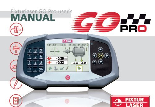
<strong>Fixturlaser</strong> GO Pro user`s<br />
MANUAL
CONTENT<br />
Introduction 1.1<br />
Declaration of Conformity 2.1<br />
Safety 3.1<br />
Care 4.1<br />
Main Menu 5.1<br />
Shaft Alignment Horizontal<br />
Machines<br />
Shaft Alignment Vertical<br />
Machines<br />
6.1<br />
7.1<br />
Machine Defined Data 8.1<br />
Softcheck 9.1<br />
Target Values 10.1<br />
Memory Manager 11.1<br />
Global Settings 12.1<br />
Display Unit GO Pro D 13.1<br />
Wireless Transceivers 14.1<br />
Technical Specification<br />
GO Pro D<br />
15.1<br />
Technical Specification M1/S1 16.1<br />
<strong>Fixturlaser</strong> GO Pro Manual 3 rd edition July 2012
<strong>Fixturlaser</strong> GO Pro Manual 3 rd edition July 2012
1 INTRODUCTION<br />
Congratulations on your choice of the<br />
<strong>Fixturlaser</strong> GO Pro!<br />
We are convinced that you have made<br />
the right decision and we hope the<br />
system will meet, and even exceed,<br />
your expectations.<br />
It is important that you read the<br />
sections about safety and care before<br />
you proceed with your first<br />
measurement.<br />
The purpose of this manual is to guide<br />
you through the different procedures<br />
and operations of the hardware and<br />
software. Since machine installations<br />
and setups are often different from each<br />
other, we have focused this manual on<br />
measurement principles and how to<br />
handle the system.<br />
The manual describes applications,<br />
functions and equipment that may be<br />
available in a <strong>Fixturlaser</strong> GO Pro<br />
system; the ones that are available in<br />
your specific system depend upon which<br />
application packages and accessories<br />
you have selected.<br />
We wish you many successful<br />
measurements!<br />
<strong>Fixturlaser</strong> GO Pro Manual 3 rd edition 1.1
END USER LICENSE AGREEMENT<br />
The rights to use the software in this<br />
product are offered only on the<br />
conditions that you agree to all the<br />
terms stated below, i.e. the end user<br />
agreement. By using this product you<br />
agree to be bound by this agreement. If<br />
you do not accept this agreement your<br />
sole remedy is to return the entire<br />
unused product, hardware and software,<br />
promptly to your place of purchase for a<br />
refund.<br />
The user is granted a single license to<br />
use the software contained in this<br />
product. Use is only permitted on the<br />
hardware it has been installed on at the<br />
time of purchase. The software may not<br />
be removed from the hardware.<br />
The software contained in the system is<br />
the property of Elos <strong>Fixturlaser</strong> AB, any<br />
copying or redistribution is strictly<br />
prohibited.<br />
Modifying, disassembling, reverse<br />
engineering or decompiling the system<br />
or any part thereof is strictly prohibited.<br />
Disclaimer of warranties: To the<br />
maximum extent permitted by<br />
applicable law, Elos <strong>Fixturlaser</strong> AB and<br />
its suppliers provide the software<br />
contained in this product ‘as is’ and with<br />
all faults, and hereby disclaim all other<br />
warranties either expressed, implied or<br />
statutory.<br />
Limited liability: No liability shall exceed<br />
the price of the product, and the sole<br />
remedy, if any, to any claim shall be a<br />
right of return and refund.<br />
Elos <strong>Fixturlaser</strong> AB or its suppliers shall,<br />
to the maximum extent permitted by<br />
applicable law, not be liable to any<br />
indirect, special, incidental, punitive,<br />
and consequential damages arising from<br />
the use of the system or any part<br />
thereof, authorized or unauthorized.<br />
<strong>Fixturlaser</strong> GO Pro Manual 3 rd edition 1.2
2 DECLARATION OF<br />
CONFORMITY<br />
In accordance with the EMC Directive<br />
2004/108/EC, the Low Voltage Directive<br />
73/23/EEC, including amendments by<br />
the CE-marking Directive 93/68/EEC &<br />
EC directives RoHS, 2002/95.<br />
Type of equipment<br />
Alignment System<br />
Brand name or trade mark<br />
<strong>Fixturlaser</strong> GO Pro<br />
Type designation(s)/Model no(s)<br />
1-0875 <strong>Fixturlaser</strong> GO Pro<br />
Manufacturer’s name, address,<br />
telephone & fax no<br />
Elos <strong>Fixturlaser</strong> AB<br />
Box 7<br />
SE-431 21 Mölndal<br />
Sweden<br />
Tel: +46 31 7062800<br />
Fax: +46 31 7062850<br />
The following standards and/or technical<br />
specifications, which comply with good<br />
engineering practice in safety matters in<br />
force within the EEA, have been applied:<br />
Standard/Test report/Technical<br />
construction file/Normative<br />
document<br />
Emission: EN 61000-6-3:2007.<br />
Immunity: EN 61000-6-2:2005, EN<br />
61000-4-2, -3.<br />
ISO9001:2008 Ref. No/ Issued by: DNV<br />
Certification AB Certification No. 2009-<br />
SKM-AQ-2704 / 2009-SKM-AE-1419.<br />
<strong>Fixturlaser</strong> GO Pro Manual 3 rd edition 2.1
The laser is classified in accordance with<br />
the International Standard IEC-60825-<br />
1:2007,<br />
USA FDA Standard 21 CFR, Ch 1, Part<br />
1040.10 and 1040.11 except for<br />
deviations pursuant to laser notice No.<br />
50, dated June 24, 2007.<br />
The wireless device complies with Part<br />
15 of the FCC Rules. Operation is<br />
subject to the following two conditions;<br />
(1) this device may not cause harmful<br />
interference, and<br />
(2) this device must accept any<br />
interference received, including<br />
interference that may cause undesired<br />
operation.<br />
Additional information<br />
The product was CE-marked in 2010.<br />
As manufacturer, we declare under our<br />
sole responsibility that the equipment<br />
follows the provisions of the Directives<br />
stated above.<br />
Date and place of issue<br />
Mölndal 2010-09-30<br />
Signature of authorized person<br />
Hans Svensson, Managing Director<br />
<strong>Fixturlaser</strong> GO Pro Manual 3 rd edition 2.2
3 SAFETY<br />
Retain and follow all product safety and<br />
operating instructions. Observe all<br />
warnings on the product and in the<br />
operating instructions.<br />
Failure to observe the safety precautions<br />
and operating instructions can<br />
cause bodily injury, fire, and damage to<br />
the equipment.<br />
Do not disassemble, modify or use the<br />
equipment in other ways than explained<br />
in the operating instructions. <strong>Fixturlaser</strong><br />
will not accept any liability for such use.<br />
WARNING!<br />
Do not mount equipment on<br />
running machines and take all<br />
appropriate measures to<br />
prevent unintentional start-up<br />
of machines. Make sure to<br />
fully comply with all<br />
appropriate shut down<br />
procedures, safety measures<br />
and regulations at worksite<br />
and local regulations<br />
regarding safety in a machine<br />
environment.<br />
<strong>Fixturlaser</strong> GO Pro Manual 3 rd edition 3.1
LASER PRECAUTIONS<br />
<strong>Fixturlaser</strong> GO Pro uses laser diodes<br />
with a power output of < 1.0 mW. The<br />
laser classification is Class 2.<br />
CAUTION!<br />
USE OF CONTROLS OR<br />
ADJUSTMENTS OR<br />
PERFORMANCE OF<br />
PROCEDURES OTHER THAN<br />
THOSE SPECIFIED HEREIN<br />
MAY RESULT IN HAZARDOUS<br />
RADIATION EXPOSURE.<br />
Class 2 is considered safe for its<br />
intended use with only minor precautions<br />
required. These are:<br />
Never stare directly into the laser<br />
transmitter.<br />
Never shine the laser directly into<br />
anyone else’s eyes.<br />
<strong>Fixturlaser</strong> GO Pro Manual 3 rd edition 3.2
Your system complies with the<br />
requirements in:<br />
SS-EN-60825-1-1994<br />
British Standard BS 4803 Parts 1<br />
to 3<br />
Deutsche Industrie Norm DIN JEC<br />
76 (CO) 6<br />
USA FDA Standard 21 CFR, Ch 1,<br />
Part 1040.10 and 1040.11<br />
POWER SUPPLY<br />
<strong>Fixturlaser</strong> GO Pro is powered by three<br />
1.5V LR-14 (C) Alkaline batteries or by<br />
corresponding 1.2V NiMH HR-14<br />
Rechargeable Nickel Metal Hydride cells.<br />
Only use high performance alkaline<br />
batteries.<br />
Remove batteries when the system is<br />
stored for prolonged periods of time.<br />
WARNING!<br />
USE OF ANY OTHER<br />
BATTERIES THAN THOSE<br />
SPECIFIED BY FIXTURLASER<br />
WILL CAUSE SEVERE<br />
DAMAGE TO THE DISPLAY<br />
UNIT AND CAN CAUSE RISK<br />
FOR PERSONAL INJURY!<br />
<strong>Fixturlaser</strong> GO Pro Manual 3 rd edition 3.3
Handle any batteries with care.<br />
Batteries pose a burn hazard if handled<br />
improperly. Do not disassemble and<br />
keep away from heat sources. Handle<br />
damaged or leaking batteries with<br />
extreme care. Please keep in mind that<br />
batteries can harm the environment.<br />
Dispose of batteries in accordance with<br />
local regulatory guidelines, if in doubt<br />
contact your local sales representative.<br />
WIRELESS TRANSCEIVER<br />
The GO Pro system is fitted with<br />
Bluetooth wireless transceivers.<br />
Make sure that there are no restrictions<br />
on the use of radio transceivers at the<br />
site of operation before using the<br />
wireless transceivers.<br />
WARNING!<br />
Before using the wireless<br />
transceivers make sure that<br />
there are no restrictions on<br />
the use of radio transceivers<br />
at the site. Do not use on<br />
aircraft.<br />
<strong>Fixturlaser</strong> GO Pro Manual 3 rd edition 3.4
4 CARE<br />
The system should be cleaned with a<br />
cotton cloth or a cotton bud moistened<br />
with a mild soap solution, with the<br />
exception of the detector and laser<br />
window surfaces, which should be<br />
cleaned with alcohol.<br />
Do not use paper tissue, which can<br />
scratch the detector surface.<br />
Do not use acetone.<br />
For the best possible function, the laser<br />
diode apertures, detector surfaces and<br />
connector terminals should be kept free<br />
from grease or dirt. The display unit<br />
should be kept clean and the screen<br />
surface protected from scratches.<br />
<strong>Fixturlaser</strong> GO Pro Manual 3 rd edition 4.1
The chains on the V-block fixtures are<br />
delivered dry. If the system is used in<br />
highly corrosive environments, the<br />
chains should be oiled.<br />
DATE OF CALIBRATION<br />
DISCREPANCY<br />
Our instruments store the electronic<br />
date of the latest calibration of the<br />
instrument. Due to production<br />
processes and storage time, this date<br />
will differ from the date of the<br />
calibration certificate. Hence, it is the<br />
date of the calibration certificate which<br />
is important and that indicates when the<br />
next calibration is due.<br />
<strong>Fixturlaser</strong> GO Pro Manual 3 rd edition 4.2
5 MAIN MENU<br />
The <strong>Fixturlaser</strong> GO Pro is provided with<br />
different programs for specific purposes.<br />
Press the red On/Off button to start the<br />
system and the Main Menu appears.<br />
Here you can select the program that<br />
you want to use.<br />
In the Main Menu you will also find the<br />
Memory Manager and Global Settings.<br />
Select icon with the arrow buttons and<br />
confirm with the OK button.<br />
<strong>Fixturlaser</strong> GO Pro Manual 3 rd edition 5.1
APPLICATION PROGRAMS<br />
Shaft Alignment Horizontal<br />
Machines<br />
Shaft Alignment Vertical<br />
Machines<br />
Machine Defined Data<br />
MEMORY MANAGER<br />
Memory Manager<br />
SYSTEM FUNCTIONS<br />
Global Settings<br />
<strong>Fixturlaser</strong> GO Pro Manual 3 rd edition 5.2<br />
Off<br />
Wireless indicator<br />
Battery indicator
6 SHAFT ALIGNMENT<br />
HORIZONTAL MACHINES<br />
INTRODUCTION<br />
Shaft alignment: Determine and adjust<br />
the relative position of two machines<br />
that are connected, such as a motor and<br />
a pump, so that the rotational centres of<br />
the shafts are collinear, when the<br />
machines are working in a normal<br />
operating condition. Correction of<br />
horizontal shaft alignment is done by<br />
moving the front and the rear pair of<br />
one machine’s feet, vertically and<br />
horizontally, until the shafts are aligned<br />
within the given tolerances. A tolerance<br />
table is available in the system.<br />
The <strong>Fixturlaser</strong> GO Pro system has two<br />
measuring units that are placed on each<br />
shaft by using the fixtures supplied with<br />
the system. After rotating the shafts<br />
into different measuring positions the<br />
system calculates the relative position<br />
between the two shafts in two planes.<br />
The distance between the two<br />
measuring planes, distance to the<br />
coupling and distances to the machine<br />
feet are entered into the system. The<br />
display box then shows the actual<br />
alignment condition together with the<br />
position of the feet. Adjustment of the<br />
machine can be made directly,<br />
according to the displayed values.<br />
The alignment results can be saved in<br />
the memory manager. The<br />
measurements in the memory manager<br />
can easily be transferred to a PC for<br />
fu<strong>rth</strong>er documentation purposes.<br />
<strong>Fixturlaser</strong> GO Pro Manual 3 rd edition 6.1
PRE-ALIGNMENT FUNCTIONS<br />
In an effort to obtain the best possible<br />
conditions for shaft alignment, it is<br />
necessary to perform some prealignment<br />
checks. In many cases it is<br />
necessary to make these checks in<br />
order to obtain precise alignment. It is<br />
often impossible to reach the desired<br />
alignment results if you do not make<br />
any pre-alignment checks.<br />
Before going on site, check the<br />
following:<br />
Safety regulations?<br />
What are the required tolerances?<br />
Any offsets for dynamic<br />
movements?<br />
Are there any restrictions for<br />
mounting the measuring system?<br />
Is it possible to rotate the shafts?<br />
What shim size is needed?<br />
Before setting up the alignment system<br />
on the machine, check the machine<br />
foundation, bolt and shim condition.<br />
Also check if there are any restrictions<br />
in adjusting the machine (if e.g. there is<br />
enough space to move the machine).<br />
After the visual checks have been<br />
performed, there are some conditions<br />
that have to be considered:<br />
Make sure the machine is off line<br />
and safety tagged.<br />
Check that the machine has the<br />
right temperature for alignment.<br />
Take away old rusty shims (check<br />
that you can remove shims).<br />
Check coupling assembly and<br />
loosen the coupling bolts.<br />
Check soft foot conditions.<br />
Mechanical looseness.<br />
<strong>Fixturlaser</strong> GO Pro Manual 3 rd edition 6.2
Check coupling and shaft run-out.<br />
Pipe work strain.<br />
Coarse alignment.<br />
Check coupling gap (axial<br />
alignment).<br />
<strong>Fixturlaser</strong> GO Pro Manual 3 rd edition 6.3
MOUNTING<br />
The sensor marked “M” should be<br />
mounted on the moveable machine and<br />
the sensor marked “S” on the stationary<br />
machine. The sensors shall be<br />
assembled on their V-block fixture, and<br />
placed on each side of the coupling.<br />
Hold the V-block fixture upright and<br />
mount it on the shafts of the<br />
measurement object.<br />
Lift the open end of the chain, tension it<br />
so that the slack is removed and attach<br />
it to the hook.<br />
<strong>Fixturlaser</strong> GO Pro Manual 3 rd edition 6.4
Firmly tighten the chain with the<br />
tensioning screw. If necessary, use the<br />
supplied tensioning tool. Do not overtighten.<br />
If the shaft diameter is too<br />
large the chains can be extended with<br />
extension chains (optional).<br />
Adjust the height of the sensor by<br />
sliding it on the posts until a line of<br />
sight is obtained for both lasers. Secure<br />
its position by locking both clamping<br />
devices on the back of both units.<br />
<strong>Fixturlaser</strong> GO Pro Manual 3 rd edition 6.5
The laser of the M-sensor can be<br />
adjusted with the adjustment screw on<br />
the top of the unit. There is normally no<br />
need to adjust the laser, but this might<br />
be necessary when measuring at long<br />
distances.<br />
NOTE: Make sure that the adjustment<br />
screw is secured with the locking nut<br />
after adjustment.<br />
Connect the cables from the wireless<br />
communication devices to the sensor<br />
units and make sure that the tightening<br />
screws are locked.<br />
Always let the cables from the wireless<br />
communication devices stay connected<br />
to the sensor units.<br />
<strong>Fixturlaser</strong> GO Pro Manual 3 rd edition 6.6
STARTING THE PROGRAM<br />
Start the program by selecting<br />
the Horizontal Shaft<br />
Alignment icon in the Main<br />
Menu and press OK.<br />
When the program is started, a<br />
tolerance table will be displayed first.<br />
Select tolerance and press OK.<br />
Go to settings for selecting<br />
settings.<br />
<strong>Fixturlaser</strong> GO Pro Manual 3 rd edition 6.7
TOLERANCE TABLE<br />
Alignment tolerances depend to a large<br />
extent on the rotation speed of the<br />
shafts. Machine alignment should be<br />
carried out within the manufacturer’s<br />
tolerances. The table provided in<br />
<strong>Fixturlaser</strong> GO Pro can be helpful if no<br />
tolerances are specified. The suggested<br />
tolerances can be used as a starting<br />
point for developing in-house tolerances<br />
when the machinery manufacturer’s<br />
recommended tolerances are not<br />
available. The tolerances are the<br />
maximum allowed deviation from<br />
desired values.<br />
Select tolerance<br />
The arrow to the left indicates selected<br />
tolerance.<br />
Select tolerance by scrolling up/down<br />
and press OK.<br />
Select the OK icon and press<br />
OK to continue to shaft<br />
alignment.<br />
<strong>Fixturlaser</strong> GO Pro Manual 3 rd edition 6.8
Enter a customized tolerance<br />
1. Scroll down to the last row.<br />
2. Enter tolerance name/rotation<br />
speed and press OK or scroll to<br />
the right.<br />
3. Enter tolerance for the angle<br />
values and press OK or scroll to<br />
the right.<br />
4. Enter tolerance for the offset<br />
values and press OK or scroll to<br />
the right.<br />
<strong>Fixturlaser</strong> GO Pro Manual 3 rd edition 6.9
SETTINGS<br />
Settings unique for this application:<br />
Sampling time<br />
Select normal or long sampling time.<br />
To change sampling time, select the<br />
sampling time icon and press OK. Select<br />
normal or long sampling time with the<br />
left/right buttons and press OK.<br />
Long sampling time is suitable for high<br />
vibration environments.<br />
Tolerance table<br />
Open the tolerance table by selecting<br />
the tolerance table icon and press OK.<br />
Unit of angularity<br />
To change unit of angularity, select the<br />
unit of angularity icon and press OK.<br />
Enter another unit of angularity and<br />
press OK.<br />
<strong>Fixturlaser</strong> GO Pro Manual 3 rd edition 6.10
Adjustable screen filter<br />
Select filter off, filter type 1, or filter<br />
type 2.<br />
To change adjustable screen filter,<br />
select the adjustable screen filter icon<br />
and press OK. Select filter off, filter type<br />
1, or filter type 2 with the left/right<br />
buttons and press OK.<br />
Note: For normal operation, the<br />
adjustable screen filter should be<br />
deactivated, and only activated in<br />
environments with severe vibrations.<br />
Screen flip<br />
Select normal screen or screen flip.<br />
To flip the screen, select the screen flip<br />
icon and press OK. Select normal screen<br />
or screen flip with the left/right buttons<br />
and press OK.<br />
Add new machine with defined data<br />
Opens window for adding a new<br />
machine with defined data to Machine<br />
Defined Data.<br />
Entered data, such as distances, Target<br />
Values and tolerances, will be saved.<br />
<strong>Fixturlaser</strong> GO Pro Manual 3 rd edition 6.11
Turn off inclinometers<br />
If the inclinometers are not functioning<br />
properly, e.g. in high vibrations, they<br />
can be disabled.<br />
Turns off the inclinometers.<br />
Measurement with disabled<br />
inclinometers is described at the end of<br />
this chapter.<br />
Exit<br />
Exits the Settings and returns<br />
to the application.<br />
<strong>Fixturlaser</strong> GO Pro Manual 3 rd edition 6.12
ENTER DIMENSIONS<br />
The screen displays the movable<br />
machine.<br />
Select the dimension<br />
boxes to enter<br />
dimensions.<br />
Measure and enter dimensions.<br />
You must enter all the distances. The<br />
distance between the sensors, the<br />
distance between the centre of the<br />
coupling and the M-sensor, the distance<br />
between the M-sensor and the first pair<br />
of feet and the distance between the<br />
first and the second pairs of feet.<br />
<strong>Fixturlaser</strong> GO Pro Manual 3 rd edition 6.13
SOFTCHECK<br />
TARGET VALUES<br />
Go to Softcheck for checking<br />
soft foot conditions.<br />
See chapter “Softcheck”.<br />
Go to Target Values for<br />
entering target values.<br />
See chapter “Target Values”.<br />
MEASUREMENT METHOD<br />
Tripoint method<br />
In the Tripoint method, the alignment<br />
condition can be calculated by taking<br />
three points while rotating the shaft at<br />
least 90°.<br />
NOTE: The shafts should be coupled<br />
during measurement in order to achieve<br />
as reliable and accurate results as<br />
possible, when using the Tripoint<br />
method.<br />
TIP: The larger the angle over which the<br />
three points are measured, the fewer<br />
moves and repeat measurements will<br />
have to be made. Minimum angle<br />
between readings is 45°.<br />
A green flashing arrow<br />
suggests suitable<br />
measurement positions.<br />
<strong>Fixturlaser</strong> GO Pro Manual 3 rd edition 6.14
MEASUREMENT POINT<br />
REGISTRATION<br />
Set the sensors so that they are<br />
approximately at the same rotational<br />
angle at the first measurement position.<br />
Select the register icon and<br />
press OK.<br />
This registers the first<br />
reading.<br />
Rotate the shafts to the next position.<br />
The shafts must be rotated over a<br />
minimum of 45°.<br />
Green sector show permitted positions.<br />
Red sector show forbidden positions.<br />
The Register icon is not shown if the<br />
rotation is less than 45°.<br />
<strong>Fixturlaser</strong> GO Pro Manual 3 rd edition 6.15
Select the register icon and<br />
press OK.<br />
This registers the second<br />
reading.<br />
Rotate the shafts to the third position.<br />
Select the register icon and<br />
press OK.<br />
This registers the third<br />
reading.<br />
TIP: By registering the third reading at<br />
the position 3 o’clock, the sensors will<br />
already be in the right position for<br />
horizontal alignment.<br />
<strong>Fixturlaser</strong> GO Pro Manual 3 rd edition 6.16
MEASUREMENT RESULTS<br />
The Measurement Result screen shows<br />
coupling values and foot values in both<br />
the vertical and horizontal direction.<br />
The symbol to the left of the coupling<br />
values indicates the angular direction<br />
and offset, and also if the values are<br />
within tolerance.<br />
Within tolerance<br />
(green).<br />
Within double tolerance<br />
(yellow).<br />
Out of double tolerance<br />
(red).<br />
A symbol at the coupling indicates the<br />
status of the coupling.<br />
Within tolerance.<br />
<strong>Fixturlaser</strong> GO Pro Manual 3 rd edition 6.17
EVALUATING THE RESULT<br />
The angle and offset values are used to<br />
determine the alignment quality. These<br />
values are compared with the alignment<br />
tolerances to determine whether<br />
correction is necessary. If suitable<br />
tolerances are selected in the tolerance<br />
table, the symbols described above<br />
indicate if the angle and offset values<br />
are within tolerance or not.<br />
The foot values indicate the movable<br />
machine’s foot positions where<br />
corrections can be made.<br />
Depending on the result, the program<br />
will also guide the user.<br />
First, the program will always<br />
recommend the user to save the<br />
measurement.<br />
Then, if the measurement result shows<br />
that the machine is misaligned, the user<br />
will be recommended to go to<br />
shimming.<br />
If the measurement result is within<br />
tolerance, the system will recommend<br />
the user to exit the measurement.<br />
Save the measurement result.<br />
Go to shimming.<br />
<strong>Fixturlaser</strong> GO Pro Manual 3 rd edition 6.18
SHIMMING<br />
The Shimming screen shows foot values<br />
in the vertical direction as suitable shim<br />
values.<br />
The arrows show if shims must be<br />
added or removed to adjust the<br />
machine in the vertical direction.<br />
The check signs show that shimming is<br />
not needed.<br />
When shimming is completed, continue<br />
to alignment for adjustments in the<br />
horizontal direction.<br />
Go to alignment.<br />
<strong>Fixturlaser</strong> GO Pro Manual 3 rd edition 6.19
ALIGNMENT<br />
If the machine has been adjusted<br />
vertically in the shimming screen, go<br />
directly to alignment in the horizontal<br />
direction.<br />
If the machine has not been adjusted in<br />
the shimming screen, alignment in the<br />
vertical direction has to be done first.<br />
Vertical direction<br />
Rotate the shafts to the 12 or 6 o’clock<br />
position to make adjustments in the<br />
vertical direction. The angle guide helps<br />
you to reach the right position.<br />
Adjust the machine vertically until the<br />
values for both angular and parallel<br />
alignment are within tolerance. The<br />
arrows at the feet show in which<br />
direction the machine shall be moved.<br />
<strong>Fixturlaser</strong> GO Pro Manual 3 rd edition 6.20
Horizontal direction<br />
Rotate the shafts to the 3 or 9 o’clock<br />
position to make adjustments in the<br />
horizontal direction. The angle guide<br />
helps you to reach the right position.<br />
Adjust the machine horizontally until the<br />
values for both angular and parallel<br />
alignment are within tolerance. The<br />
arrows at the feet show in which<br />
direction the machine shall be moved.<br />
Check and re-measure<br />
Rotate the shafts back to the 12 or 6<br />
o’clock position and check that the<br />
machine is still within tolerance.<br />
Alignment is now completed. To confirm<br />
the result, re-do the measurement.<br />
Re-measure.<br />
<strong>Fixturlaser</strong> GO Pro Manual 3 rd edition 6.21
OTHER FEATURES<br />
M and S unit LED function<br />
The front of the M and S units has two<br />
LEDs.<br />
Laser operation LED (close to laser):<br />
Continuously<br />
green:<br />
Laser is firing.<br />
Status LED (close to detector):<br />
Continuously<br />
green:<br />
Unit OK and<br />
ready.<br />
Continuously red: Unit start up or<br />
malfunction during<br />
start up.<br />
Flashing green: Unit placed at 9,<br />
12 or 3 o’clock<br />
positions (within<br />
+/-3°).<br />
Flashing red: Measurement in<br />
progress.<br />
Looseness indicator<br />
The system has a function for detecting<br />
coupling backlash and looseness in<br />
order to achieve optimal accuracy. The<br />
system will display the looseness<br />
indicator if one of the following<br />
conditions is met:<br />
The M and S units are more than<br />
3° apart.<br />
The mutual angular position of<br />
the M and S units changes more<br />
than 0.7° at the following<br />
measurement points, compared<br />
to the first measurement point.<br />
When the coupling backlash or<br />
looseness is eliminated to avoid any of<br />
the above conditions, the looseness<br />
indicator will automatically disappear.<br />
<strong>Fixturlaser</strong> GO Pro Manual 3 rd edition 6.22
Target Value symbol<br />
When Target Values are used<br />
in the measurement, this is<br />
indicated with the Target<br />
Value symbol in the upper<br />
right corner of the screen.<br />
Screen flip<br />
The screen can be flipped to get the<br />
motor at the left side.<br />
Select screen flip in settings.<br />
<strong>Fixturlaser</strong> GO Pro Manual 3 rd edition 6.23
Measurement with disabled<br />
inclinometers<br />
If the inclinometers are not functioning<br />
properly, e.g. in high vibrations, they<br />
can be disabled.<br />
Turn off the inclinometers in<br />
Settings.<br />
When the inclinometers are disabled the<br />
system will work as normal with the<br />
following exceptions:<br />
The readings have to be<br />
registered according to the "clock<br />
method". Register the first<br />
reading at 9 o'clock, rotate the<br />
shafts 180° and register<br />
the second reading at 3 o'clock,<br />
rotate 90° back to 12 o'clock<br />
to register the third and final<br />
reading.<br />
During alignment, use the up and<br />
down buttons to change from<br />
horizontal to vertical view of the<br />
machine and vice versa.<br />
Change view.<br />
<strong>Fixturlaser</strong> GO Pro Manual 3 rd edition 6.24
7 SHAFT ALIGNMENT<br />
VERTICAL MACHINES<br />
INTRODUCTION<br />
Shaft alignment: Determine and adjust<br />
the relative position of two machines<br />
that are connected, such as a motor and<br />
a pump, so that the rotational centres of<br />
the shafts are collinear, when the<br />
machines are working at a normal<br />
operating temperature. Correction of<br />
vertical shaft alignment is done by<br />
moving the flange of the machine until<br />
the shafts are aligned within given<br />
tolerances. A tolerance table is available<br />
in the system.<br />
The <strong>Fixturlaser</strong> system has two<br />
measuring units that are placed on each<br />
shaft by using the fixtures supplied with<br />
the system. After rotating the shafts to<br />
different measuring positions, the<br />
system calculates the relative position<br />
between the two shafts in two planes.<br />
The distance between the two<br />
measuring planes, distance to the<br />
coupling, number of bolts and pitch<br />
circle diameter are entered into the<br />
system. The display box then shows the<br />
actual alignment condition together with<br />
the position of the feet. Adjustment of<br />
the machine can be made according to<br />
the values displayed. The angular<br />
misalignment is corrected by placing<br />
shims under the bolts and offset is<br />
corrected by moving the machine<br />
laterally.<br />
The alignment results can be saved in<br />
the memory manager. The<br />
measurements in the memory manager<br />
can easily be transferred to a PC for<br />
fu<strong>rth</strong>er documentation purposes.<br />
<strong>Fixturlaser</strong> GO Pro Manual 3 rd edition 7.1
PRE-ALIGNMENT FUNCTIONS<br />
In an effort to obtain the best possible<br />
conditions for shaft alignment, it is<br />
necessary to perform some prealignment<br />
checks. In many cases it is<br />
necessary to make these checks in<br />
order to obtain precise alignment. It is<br />
often impossible to reach the desired<br />
alignment results if you do not make<br />
any pre-alignment checks.<br />
Before going on site, check the<br />
following:<br />
Safety regulations?<br />
What are the required tolerances?<br />
Any offsets for dynamic<br />
movements?<br />
Are there any restrictions for<br />
mounting the measuring system?<br />
Is it possible to rotate the shafts?<br />
What shim size is needed?<br />
Before setting up the alignment system<br />
on the machine, check the machine<br />
foundation, bolt and shim conditions.<br />
Also check if there are any restrictions<br />
in adjusting the machine (if e.g. there is<br />
enough space to move the machine).<br />
After the visual checks have been<br />
performed, there are some conditions<br />
that have to be considered:<br />
Make sure the machine is off line<br />
and safety tagged.<br />
Check that the machine has the<br />
right temperature for alignment?<br />
Take away old rusty shims (check<br />
that you can remove shims).<br />
Check coupling assembly and<br />
loosen the coupling bolts.<br />
Check soft foot conditions.<br />
Mechanical looseness.<br />
<strong>Fixturlaser</strong> GO Pro Manual 3 rd edition 7.2
Check coupling and shaft run-out.<br />
Pipe work strain.<br />
Coarse alignment.<br />
Check coupling gap (axial<br />
alignment).<br />
MOUNTING<br />
The sensors are mounted as described<br />
in chapter “Shaft Alignment Horizontal<br />
Machines”.<br />
STARTING THE PROGRAM<br />
Start the program by<br />
selecting the Vertical Shaft<br />
Alignment icon in the Main<br />
Menu and press OK.<br />
Go to Settings for<br />
selecting settings.<br />
<strong>Fixturlaser</strong> GO Pro Manual 3 rd edition 7.3
SETTINGS<br />
Settings unique for this application:<br />
Sampling time<br />
Select normal or long sampling time.<br />
To change sampling time, select the<br />
sampling time icon and press OK. Select<br />
normal or long sampling time with the<br />
left/right buttons and press OK.<br />
Long sampling time is suitable for high<br />
vibration environments.<br />
Tolerance table<br />
Open the tolerance table by selecting<br />
the tolerance table icon and press OK.<br />
The tolerance table is described in the<br />
chapter “Shaft Alignment Horizontal<br />
Machines”.<br />
<strong>Fixturlaser</strong> GO Pro Manual 3 rd edition 7.4
Adjustable screen filter<br />
Select filter off, filter type 1, or filter<br />
type 2.<br />
To change adjustable screen filter,<br />
select the adjustable screen filter icon<br />
and press OK. Select filter off, filter type<br />
1, or filter type 2 with the left/right<br />
buttons and press OK.<br />
Note: For normal operation, the<br />
adjustable screen filter should be<br />
deactivated, and only activated in<br />
environments with severe vibrations.<br />
Exit<br />
Exits the Settings and returns<br />
to the application.<br />
<strong>Fixturlaser</strong> GO Pro Manual 3 rd edition 7.5
ENTER DIMENSIONS<br />
The screen displays the movable<br />
machine.<br />
Select the dimension<br />
boxes to enter dimensions.<br />
Measure and enter dimensions.<br />
You must enter all the distances. The<br />
distance between the sensors, the<br />
distance between the centre of the<br />
coupling and the M-sensor, and the<br />
pitch circle diameter and the number of<br />
bolts.<br />
Up to 8 bolts can be entered.<br />
MEASUREMENT METHOD<br />
In the Vertical Shaft Alignment<br />
program, machinery positions are<br />
calculated by taking three points with<br />
180° of rotation.<br />
<strong>Fixturlaser</strong> GO Pro Manual 3 rd edition 7.6
MEASUREMENT POINT<br />
REGISTRATION<br />
Place yourself at the position<br />
corresponding to the second<br />
measurement position, where it is<br />
easiest to turn the shafts through 180°.<br />
Tip: Mark the positions 1, 2 and 3<br />
before you start measuring.<br />
Set the sensors at approximately the<br />
same rotational angle at the first<br />
measurement position, with bolt<br />
number 1 to the right.<br />
Select the register icon and<br />
press OK.<br />
This registers the first<br />
reading.<br />
<strong>Fixturlaser</strong> GO Pro Manual 3 rd edition 7.7
Rotate the shafts 90° to the second<br />
position (where you are standing).<br />
Select the register icon and<br />
press OK.<br />
This registers the second<br />
reading.<br />
Rotate the shafts 90° to the third<br />
position, to the left.<br />
Select the register icon and<br />
press OK.<br />
This registers the third<br />
reading.<br />
<strong>Fixturlaser</strong> GO Pro Manual 3 rd edition 7.8
MEASUREMENT RESULTS<br />
The Measurement Result screen shows<br />
coupling values in both directions, and<br />
bolt values.<br />
The symbol to the left of the coupling<br />
values indicates the angular direction<br />
and offset, and also if the values are<br />
within tolerance.<br />
Within tolerance (green).<br />
Within double tolerance<br />
(yellow).<br />
Out of double tolerance (red).<br />
A symbol at the coupling indicates the<br />
status of the coupling.<br />
Within tolerance.<br />
Save the measurement result.<br />
Go to alignment.<br />
<strong>Fixturlaser</strong> GO Pro Manual 3 rd edition 7.9
EVALUATING THE RESULT<br />
The angle and offset values are used to<br />
determine the alignment quality. These<br />
values are compared with alignment<br />
tolerances to determine if any correction<br />
is necessary. If suitable tolerances are<br />
selected in the tolerance table, the<br />
symbols described above indicate if the<br />
angle and offset values are within<br />
tolerance or not.<br />
The foot values indicate the movable<br />
machine’s foot positions where<br />
corrections can be made.<br />
<strong>Fixturlaser</strong> GO Pro Manual 3 rd edition 7.10
ALIGNMENT<br />
Adjust the angular error by placing<br />
shims under the bolts as required<br />
(negative bolt value means that shims<br />
should be added.) The angular error is<br />
displayed live in the first direction when<br />
the sensors are placed in position<br />
number 1, and in the second direction<br />
when they are placed in position<br />
number 2.<br />
Now adjust the parallel offset in both<br />
directions by moving the machine. The<br />
parallel offset is displayed live in the<br />
first direction when the sensors are<br />
placed in position number 1, and in the<br />
second direction when they are placed<br />
in position number 2.<br />
Check that both the angular value and<br />
the parallel offset lie within the required<br />
tolerances once the adjustments are<br />
completed.<br />
Alignment is now complete. To confirm<br />
the result, re-do the measurement.<br />
Re-measure.<br />
<strong>Fixturlaser</strong> GO Pro Manual 3 rd edition 7.11
<strong>Fixturlaser</strong> GO Pro Manual 3 rd edition 7.12
8 MACHINE DEFINED DATA<br />
INTRODUCTION<br />
If the sensors are placed at the same<br />
place each time a machine (or more<br />
identical machines) is measured, it can<br />
be convenient to preload the relevant<br />
parameters. The data that can be<br />
preloaded is:<br />
The name of the specific machine,<br />
Distances for the machine, the<br />
distance between the sensors<br />
(where fixture points are fixed),<br />
the distance between the centre<br />
of the coupling and the M-sensor,<br />
the distance between the Msensor<br />
and the first pair of feet<br />
and the distance between the first<br />
and the second pairs of feet,<br />
Target Values as feet values or<br />
angle and offset values.<br />
Tolerances.<br />
NOTE!<br />
When using Machine Defined<br />
Data, the sensors must<br />
always be placed according to<br />
the preloaded distances to get<br />
correct measurement results.<br />
<strong>Fixturlaser</strong> GO Pro Manual 3 rd edition 8.1
STARTING THE PROGRAM<br />
Start the program by<br />
selecting the Machine Defined<br />
Data icon in the Main Menu<br />
and press OK.<br />
USING MACHINE DEFINED DATA<br />
A list of machine types with preloaded<br />
data is shown.<br />
Select machine<br />
Machines can be selected by scrolling.<br />
Scroll upwards.<br />
Scroll downwards.<br />
Continue to Shaft Alignment<br />
Continue to Shaft Alignment<br />
with machine defined data for<br />
the selected machine.<br />
<strong>Fixturlaser</strong> GO Pro Manual 3 rd edition 8.2
9 SOFTCHECK<br />
INTRODUCTION<br />
A soft foot condition needs to be<br />
corrected before any alignment takes<br />
place. If not, the measurement result<br />
will be of no value. It is more or less<br />
impossible to establish if there is a soft<br />
foot condition without using some kind<br />
of measurement tool. The <strong>Fixturlaser</strong><br />
Alignment System’s built-in Softcheck<br />
program checks each foot and displays<br />
the result in mm or mils.<br />
The Softcheck program is entered from<br />
the Horizontal Shaft Alignment program.<br />
STARTING THE PROGRAM<br />
Start the Softcheck by<br />
selecting its icon in the Shaft<br />
Alignment program and press<br />
OK.<br />
Place the sensors at the 12 o’clock<br />
position.<br />
All the distances must be entered,<br />
before checking for soft foot.<br />
Check that all foot bolts are firmly<br />
tightened.<br />
<strong>Fixturlaser</strong> GO Pro Manual 3 rd edition 9.1
MEASUREMENT VALUE<br />
REGISTRATION<br />
Select a bolt of your<br />
choice and press OK.<br />
Loosen the bolt fully and then tighten it<br />
firmly, preferably with a dynamometric<br />
wrench.<br />
Press OK to register the<br />
measurement value.<br />
<strong>Fixturlaser</strong> GO Pro Manual 3 rd edition 9.2
Continue with the rest of the bolts.<br />
Re-measurements can be done at any<br />
time by selecting the requested bolt<br />
again and press OK.<br />
Make the necessary corrections and<br />
then check each foot again (the values<br />
show approximately how many shims<br />
that are needed to eliminate the soft<br />
foot).<br />
<strong>Fixturlaser</strong> GO Pro Manual 3 rd edition 9.3
SHAFT ALIGNMENT<br />
Return to shaft alignment by<br />
selecting the Exit icon and<br />
press OK.<br />
<strong>Fixturlaser</strong> GO Pro Manual 3 rd edition 9.4
10 TARGET VALUES<br />
INTRODUCTION<br />
Most machines develop a certain<br />
amount of heat while running. In the<br />
best case both the driving and the<br />
driven machine are affected equally<br />
requiring no input of compensation<br />
values. But in some applications the<br />
driven machine is either hotter, i.e. a<br />
pump for hot liquid, or cooler than the<br />
driving machine.<br />
Machine manufacturers define the<br />
thermal expansion of machines<br />
differently, but in most cases you will<br />
find it as a factor of deliberate<br />
misalignment expressed in parallel<br />
offset and angular error.<br />
In the <strong>Fixturlaser</strong> GO Pro system, you<br />
can enter target values while doing your<br />
alignment work. Accepted values are<br />
feet values and angle and offset values.<br />
The entered values are target values.<br />
Target values mean that these are the<br />
values at which the machine should be<br />
positioned when not running (cold<br />
condition) in order to obtain correct<br />
alignment while the machine is running<br />
(hot condition).<br />
<strong>Fixturlaser</strong> GO Pro Manual 3 rd edition 10.1
STARTING THE PROGRAM<br />
Start the Target Values<br />
program by selecting its icon<br />
in the Horizontal Shaft<br />
Alignment program and press<br />
OK.<br />
Select one of two ways to express the<br />
offset values: Feet values or angle and<br />
offset values.<br />
FEET VALUES<br />
Select the feet value boxes. Enter target<br />
values for the feet in mm or mils<br />
according to the pre-set measurement<br />
unit together with the required<br />
distances.<br />
<strong>Fixturlaser</strong> GO Pro Manual 3 rd edition 10.2
In the example above, the stationary<br />
machine will shrink vertically by 0.12<br />
mm at the rear feet and 0.09 mm at<br />
front feet while the movable machine<br />
will expand 0.04 mm while running.<br />
Horizontally, the rear feet will move<br />
0.05 mm towards you and the front feet<br />
will move 0.03 mm away from you while<br />
the movable machine does not change<br />
its position while running.<br />
After having entered these feet values,<br />
the system calculates how the movable<br />
machine should be positioned (target<br />
position) in cold condition in order to<br />
obtain perfect alignment during running<br />
condition.<br />
<strong>Fixturlaser</strong> GO Pro Manual 3 rd edition 10.3
ANGLE AND OFFSET VALUES<br />
Select the value boxes and enter target<br />
values for the angles in mm/100 mm<br />
and target values for the offsets in mm,<br />
or mils/inch and mils, according to the<br />
pre-set measurement unit.<br />
In the example above, the movable<br />
machine should be vertically adjusted to<br />
a position with an angular misalignment<br />
of +0.05 mm/100 mm and an offset of<br />
-0.06 mm.<br />
Horizontally, the movable machine<br />
should be positioned with a<br />
+0.02 mm/100 mm angular<br />
misalignment and a +0.03 mm offset, in<br />
cold condition to obtain perfect<br />
alignment while running.<br />
<strong>Fixturlaser</strong> GO Pro Manual 3 rd edition 10.4
SHAFT ALIGNMENT<br />
Return to shaft alignment by<br />
selecting the Exit icon and<br />
press OK.<br />
<strong>Fixturlaser</strong> GO Pro Manual 3 rd edition 10.5
<strong>Fixturlaser</strong> GO Pro Manual 3 rd edition 10.6
11 MEMORY MANAGER<br />
FILE MANAGER<br />
Select file<br />
Files can be selected by scrolling.<br />
Scroll upwards.<br />
Scroll downwards.<br />
Open file<br />
Archive<br />
Delete<br />
Opens selected file.<br />
Goes to archive<br />
(only available when it<br />
contains folders with older<br />
files).<br />
Deletes selected file.<br />
<strong>Fixturlaser</strong> GO Pro Manual 3 rd edition 11.1<br />
Exit<br />
Exits the Memory Manager.
The Memory has the capacity to store<br />
approximately 1500 measurements.<br />
When the number of measurements,<br />
exceeds 100 measurements in the file<br />
manager, a folder with the older files<br />
will be automatically created. These<br />
folders can then be found in the archive.<br />
NOTE: When there are a lot of files in<br />
the memory, processing can be slow.<br />
<strong>Fixturlaser</strong> GO Pro Manual 3 rd edition 11.2
SAVE MEASUREMENT<br />
Enter file name<br />
Enter file name with the keyboard,<br />
when the file name field is selected.<br />
Confirm<br />
Confirm.<br />
When saving a measurement, both a<br />
text file and a picture file (bmp) are<br />
created.<br />
<strong>Fixturlaser</strong> GO Pro Manual 3 rd edition 11.3
TRANSFER FILES TO A PC<br />
1. Turn on the display unit and<br />
stay in the Main Menu.<br />
2. Attach the display unit to the<br />
PC with the USB cable. The<br />
display unit will be<br />
automatically detected and will<br />
appear as a mass storage<br />
device on the PC.<br />
NOTE: The display unit must<br />
be turned on and in the Main<br />
Menu before it is connected to<br />
the PC in order for the display<br />
unit to appear on the PC.<br />
3. The files in the display unit can<br />
be transferred to the PC using<br />
the ordinary functions in<br />
Windows Explorer (i.e. cut,<br />
copy or drag and drop).<br />
In the PC there will be two files for each<br />
measurement; a picture file (.bmp) and<br />
a text file (.txt). The picture file shows<br />
the same picture as in the memory. The<br />
text file shows just the measurement<br />
data.<br />
It is recommended that you delete the<br />
files from the display unit after they<br />
have been safely transferred in order to<br />
avoid full memory.<br />
<strong>Fixturlaser</strong> GO Pro Manual 3 rd edition 11.4
SHAFT ALIGNMENT FOR<br />
HORIZONTAL MACHINES<br />
The screen displays measurement<br />
results, dimensions, target values if<br />
any, file name, date and time, serial<br />
number of the display unit, program,<br />
program version, calibration date and<br />
tolerances.<br />
Exits the measurement file.<br />
Scrolls to measurement saved<br />
after the one displayed.<br />
Scrolls to measurement saved<br />
prior to the one displayed.<br />
Deletes the measurement file.<br />
<strong>Fixturlaser</strong> GO Pro Manual 3 rd edition 11.5
SHAFT ALIGNMENT FOR VERTICAL<br />
MACHINES<br />
The screen displays measurement<br />
results, dimensions, file name, date and<br />
time, serial number of the display unit,<br />
program, program version, calibration<br />
date and tolerances.<br />
Exits the measurement file.<br />
Scrolls to measurement saved<br />
after the one displayed.<br />
Scrolls to measurement saved<br />
prior to the one displayed.<br />
Deletes the measurement file.<br />
<strong>Fixturlaser</strong> GO Pro Manual 3 rd edition 11.6
12 GLOBAL SETTINGS<br />
The global settings menu includes<br />
settings that are universal for all<br />
applications.<br />
For most of the settings, the current<br />
selection is shown in the icon.<br />
The program version number is also<br />
shown on this screen.<br />
Date<br />
Date settings<br />
To change date, select the date icon and<br />
press OK. Enter year and press OK.<br />
Enter month and press OK. Enter day<br />
and press OK.<br />
Time<br />
Time settings<br />
To change time, select the time icon<br />
and press OK. Enter hour and press OK.<br />
Enter minute and press OK.<br />
<strong>Fixturlaser</strong> GO Pro Manual 3 rd edition 12.1
Measurement unit<br />
Changes between mm mode and inch<br />
mode<br />
To change measurement unit, select the<br />
measurement unit icon and press OK.<br />
Select mm or inch with the left/right<br />
buttons and press OK.<br />
Battery type<br />
Changes between standard batteries<br />
and rechargeable batteries<br />
To change battery type, select the<br />
battery type icon and press OK. Select<br />
standard batteries or rechargeable<br />
batteries with the left/right buttons and<br />
press OK.<br />
Wireless settings<br />
Wireless settings<br />
See chapter “Wireless Transceivers”.<br />
Open the wireless settings by selecting<br />
the wireless settings icon and press OK.<br />
<strong>Fixturlaser</strong> GO Pro Manual 3 rd edition 12.2<br />
Exit<br />
Exits the global settings.
13 DISPLAY UNIT<br />
GO PRO D<br />
1 2<br />
4 5<br />
1. Alfa-numeric keyboard<br />
2. LED indicator<br />
3. On/Off button<br />
4. Navigation buttons<br />
<strong>Fixturlaser</strong> GO Pro Manual 3 rd edition 13.1
1. USB slave<br />
1<br />
OPERATING MODES<br />
The display unit has two operating<br />
modes: On and Off.<br />
The display unit is turned on by a short<br />
press on the On/Off button.<br />
To turn off the unit, select the<br />
Off icon in the main menu and<br />
press OK or while in the main<br />
menu press the On/Off button<br />
on the front.<br />
In case the system fails to respond,<br />
remove the batteries and reinstall them.<br />
<strong>Fixturlaser</strong> GO Pro Manual 3 rd edition 13.2
CONNECTIONS<br />
USB slave; for attaching the DU<br />
to a PC.<br />
WARNING!<br />
To fulfill the IP 54<br />
classification, the lids<br />
protecting the USB port must<br />
be properly sealed. Do not<br />
use the USB connection in<br />
wet conditions.<br />
POWER SUPPLY<br />
<strong>Fixturlaser</strong> GO Pro is powered by three<br />
1.5V LR-14 (C) Alkaline batteries or by<br />
1.2V NiMH HR-14 Rechargeable Nickel<br />
Metal Hydride cells.<br />
Only use high performance alkaline<br />
batteries.<br />
The operating time of the batteries is<br />
approximately 30 hours when the<br />
system is used for a typical alignment<br />
job. The power indicator in the main<br />
menu displays the capacity of the<br />
batteries. When the capacity is low, a<br />
battery low warning appears on the<br />
screen.<br />
Remove batteries when the system is<br />
stored for prolonged periods of time.<br />
<strong>Fixturlaser</strong> GO Pro Manual 3 rd edition 13.3
BACKLIGHT<br />
If no button is pressed within 15<br />
minutes the backlight will turn off<br />
automatically.<br />
Press one of the navigation buttons to<br />
turn the backlight on again.<br />
AUTO-OFF<br />
If no button is pressed within 60<br />
minutes the system will turn off<br />
automatically.<br />
RESUME FUNCTION<br />
If the system is turned off due to low<br />
power or auto-off, the resume function<br />
will save the data.<br />
When the system is turned on again<br />
after battery exchange or auto-off, you<br />
will be prompted to choose whether to<br />
return to the stage when the system<br />
was turned off (i.e. resuming operation<br />
without loss of data) or start the main<br />
menu.<br />
<strong>Fixturlaser</strong> GO Pro Manual 3 rd edition 13.4
UPGRADING THE SOFTWARE<br />
Any upgrades of the software will be<br />
distributed or made available for<br />
download on our website.<br />
1. Turn on the display unit and<br />
stay in the Main Menu.<br />
2. Attach the display unit to the<br />
PC with the USB cable. The<br />
display unit will be<br />
automatically detected and will<br />
appear as a mass storage<br />
device on the PC.<br />
NOTE: The display unit must<br />
be turned on and in the Main<br />
Menu before it is connected to<br />
the PC in order for the display<br />
unit to appear on the PC.<br />
3. Copy the file containing the<br />
new software to the display<br />
unit.<br />
NOTE: A zipped file must be<br />
unzipped before copying it to<br />
the display unit.<br />
4. Disconnect the display unit<br />
from the PC and wait until the<br />
display unit turns itself off (this<br />
can take several minutes).<br />
5. Turn on the display unit. The<br />
upgrade file will be<br />
automatically detected and<br />
installed. This can take<br />
approximately one minute.<br />
Wait until the Main Menu is<br />
displayed, and the DU is then<br />
ready to be used again.<br />
Settings and stored measurements will<br />
not be affected by an upgrade.<br />
<strong>Fixturlaser</strong> GO Pro Manual 3 rd edition 13.5
The upgrade file will be automatically<br />
deleted from the display unit when the<br />
upgrade is completed.<br />
<strong>Fixturlaser</strong> GO Pro Manual 3 rd edition 13.6
14 WIRELESS<br />
TRANSCEIVERS<br />
The wireless transceivers/battery packs<br />
uses standard Bluetooth technology.<br />
1<br />
2<br />
3<br />
4<br />
1. Battery status indicator.<br />
a. Flashing red – low<br />
battery.<br />
2. Status indicator.<br />
a. Continuously green –<br />
ON and connected.<br />
b. Flashing green – ON<br />
and trying to connect.<br />
3. On/Off button.<br />
4. Battery compartment.<br />
<strong>Fixturlaser</strong> GO Pro Manual 3 rd edition 14.1
OPERATION<br />
In order for the display unit to<br />
communicate with the wireless units<br />
they need to be paired. This is normally<br />
done at the factory when a system is<br />
ordered. If this is not the case please<br />
refer to the section “Pairing wireless<br />
units”.<br />
The communication mode also needs to<br />
be set to wireless on. (See the wireless<br />
settings part below.)<br />
WARNING!<br />
Before using the wireless<br />
option make sure that there<br />
are no restrictions on radio<br />
transceivers on the site. Do<br />
not use on aircraft.<br />
For the fastest connection turn on the<br />
wireless units/battery packs before<br />
turning on the display unit. It can take<br />
up to one minute for the wireless units<br />
to connect. When connected the status<br />
LED will become continuously green.<br />
Long distances and rough environments<br />
can affect the data transmission speed<br />
adversely. This will make the display<br />
unit appear slower.<br />
If the connection for some reason<br />
should be lost, the system will try to<br />
resend messages for 5 seconds after<br />
which it will automatically try to<br />
reconnect.<br />
<strong>Fixturlaser</strong> GO Pro Manual 3 rd edition 14.2
POWER SUPPLY<br />
Each wireless unit/battery pack contains<br />
3 AA (LR6) batteries. These batteries<br />
are used to supply power both to the<br />
wireless unit as well as to the sensor it<br />
is connected to.<br />
When connected to <strong>Fixturlaser</strong> M1 or S1<br />
the operating time will be over 8 hours<br />
continuously measuring.<br />
The battery warning LED will flash when<br />
the batteries need to be replaced.<br />
Note: Turn the wireless units/battery<br />
packs off before attempting to replace<br />
the batteries.<br />
Battery replacement<br />
<strong>Fixturlaser</strong> GO Pro Manual 3 rd edition 14.3<br />
1<br />
3<br />
2
WIRELESS SETTINGS<br />
The Wireless Settings are accessed from<br />
the Global Settings.<br />
Information on which units are paired to<br />
the display unit is displayed. The display<br />
unit will only communicate with units<br />
that are paired.<br />
There is also a battery indicator for each<br />
wireless unit (requires that the unit is<br />
turned on and that the wireless link is<br />
on).<br />
Communication mode<br />
Changes between wireless on and off.<br />
To change communication mode, select<br />
the communication mode icon and press<br />
OK. Select wireless on or off with the<br />
left/right buttons and press OK.<br />
You have to exit the settings menu in<br />
order for the changes to take place.<br />
<strong>Fixturlaser</strong> GO Pro Manual 3 rd edition 14.4
Pairing wireless units<br />
If no units are displayed in window<br />
touch the search icon to search for units<br />
that are available. If there already are<br />
units paired to the display unit press the<br />
delete icon to release them.<br />
Search for wireless battery<br />
packs.<br />
Release paired wireless<br />
battery packs.<br />
When the search is finished a list of pair<br />
able units will be displayed. Notice – the<br />
wireless units/battery packs must be<br />
switched on for the display unit to<br />
discover them. The display unit will only<br />
discover units approved by <strong>Fixturlaser</strong>.<br />
<strong>Fixturlaser</strong> GO Pro Manual 3 rd edition 14.5
Choose the unit to pair with<br />
the display unit from the list.<br />
That unit will be automatically<br />
paired and stored by the<br />
display unit.<br />
Select the OK icon and press<br />
OK to confirm wireless<br />
settings.<br />
<strong>Fixturlaser</strong> GO Pro Manual 3 rd edition 14.6
TROUBLESHOOTING<br />
There are three major factors that can<br />
affect the system’s ability to connect<br />
and communicate; distance between<br />
transceivers, obstructions between<br />
transceivers and electromagnetic<br />
interference.<br />
The wireless units will not connect<br />
Try these steps until the units connect:<br />
Make sure that communication<br />
mode Wireless is on.<br />
Go into the setting and check that<br />
the wireless units that are used<br />
are paired with this display unit.<br />
If possible bring the wireless units<br />
and the display unit close<br />
together without any obstructing<br />
objects between them – wait one<br />
minute.<br />
Restart the wireless units – wait<br />
one minute.<br />
Turn off both the wireless units<br />
and the display unit. Restart the<br />
wireless units. Restart the display<br />
unit. Wait one minute.<br />
Go into the settings and release<br />
the paired unit. Search for pairable<br />
units. If none are available<br />
they are either out of range, or<br />
unable to communicate due to<br />
interference or damage. If the<br />
units are available, choose them<br />
and they will be paired and<br />
automatically connected when the<br />
settings menu is exited.<br />
If still not connected, try at<br />
another location or contact your<br />
nearest <strong>Fixturlaser</strong> representative.<br />
<strong>Fixturlaser</strong> GO Pro Manual 3 rd edition 14.7
<strong>Fixturlaser</strong> GO Pro Manual 3 rd edition 14.8
15 TECHNICAL SPECIFICATION –<br />
FIXTURLASER GO PRO D<br />
GO Pro D Part. No. 1-0876<br />
Housing material High impact ABS plastic and TPE rubber<br />
Operating temperature -10 to 60°C ( 14 to 140°F)<br />
Storage temperature -20 to 70°C ( -4 to 158°F)<br />
Relative humidity 10 – 90%<br />
Weight 0.7 kg (1.54 lbs) with batteries<br />
Dimensions 205 mm x 116 mm x 56 mm (8.1 in x 4.6<br />
in x 2.2 in)<br />
Environmental protection IP 54<br />
Flash storage memory 500 MB<br />
Display Colour TFT-LCD backlit<br />
Display size 4” diagonal (84 x 56 mm)<br />
Display resolution 400x272 pixels<br />
Colour depth 16 000 000 colors<br />
Interface Membrane Switch Keyboard<br />
<strong>Fixturlaser</strong> GO Pro Manual 3 rd edition 15.1
Peripherals 1 USB slave port<br />
Wireless communication Class I Bluetooth transceiver with multidrop<br />
capability<br />
Power supply 3 x 1.5V LR-14 (C) Alkaline batteries or<br />
1.2V NiMH HR-14 Rechargeable Nickel<br />
Metal Hydride cells.<br />
Operating time 30 hours typical use<br />
LED indicator Green/Red<br />
<strong>Fixturlaser</strong> GO Pro Manual 3 rd edition 15.2
16 TECHNICAL SPECIFICATION – FIXTURLASER M1/S1<br />
M1 Part. No: 1-0754<br />
S1 Part. No: 1-0755<br />
Housing material Anodized aluminum and high impact ABS<br />
plastic over molded with TPE rubber<br />
Operating temperature -10° to 60°C (14 to 140°F)<br />
Storage temperature -20 to 70°C (-4 to 158°F)<br />
Relative humidity 10 – 90%<br />
Weight 186 g (6,56 oz)<br />
Dimensions 79 mm x 77 mm x 33 mm<br />
Environmental protection IP 65<br />
(3.1 in x 3.0 in x 1.3 in)<br />
Laser 650 nm class II diode laser<br />
Laser line fan angle 6°<br />
Laser line width (1/e 2 ) 1.6 mm<br />
Laser line divergence (full angle) 0.25 mrad<br />
Laser power < 1 mW<br />
<strong>Fixturlaser</strong> GO Pro Manual 3 rd edition 16.1
Measurement distance Up to 10m<br />
Detector CCD<br />
Detector length 30 mm (1.2 in)<br />
Detector angular sub tense 30 mrad/m (3 mm/100 mm per meter)<br />
Detector resolution 1 µm<br />
Measurement accuracy 0.3% ± 7 µm<br />
Ambient light protection Optical filtering and ambient light signal<br />
rejection<br />
Inclinometer resolution 0.1°<br />
Inclinometer accuracy ±0.5°<br />
LED indicators Laser transmission and status indicators<br />
<strong>Fixturlaser</strong> GO Pro Manual 3 rd edition 16.2
Publication No. P-0231-GB<br />
3rd edition, July 2012<br />
© 2012 Elos <strong>Fixturlaser</strong> AB, Mölndal, Sweden<br />
All rights reserved. No part of this manual may be copied or<br />
reproduced in any form or by any means without prior permission<br />
from Elos <strong>Fixturlaser</strong> AB.<br />
www.fixturlaser.com