user´s manual fixturlaser xa geometry
user´s manual fixturlaser xa geometry
user´s manual fixturlaser xa geometry

Create successful ePaper yourself
Turn your PDF publications into a flip-book with our unique Google optimized e-Paper software.
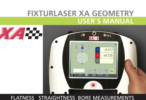
FixtUrlaser <strong>xa</strong> GeoMetry<br />
User´s ManUal<br />
FLATNESS STRAIGHTNESS BORE MEASUREMENTS
CONTENT<br />
Introduction 1.1<br />
Declaration of Conformity 2.1<br />
Main Menu 3.1<br />
Straightness Measurement 4.1<br />
Rectangular Flatness<br />
Measurement<br />
5.1<br />
Circular Flatness Measurement 6.1<br />
Memory Manager 7.1<br />
Receivers RM & RS 8.1<br />
Laser Transmitter T110 9.1<br />
Laser Transmitter T111 10.1<br />
Laser Transmitter T21 11.1<br />
Laser Transmitter T220 12.1<br />
Laser Modules TM & TS 13.1<br />
Wireless Option 14.1<br />
Technical Specification<br />
RM & RS<br />
15.1<br />
Technical Specification T110 16.1<br />
Technical Specification T111 17.1<br />
Technical Specification T21 18.1<br />
Technical Specification T220 19.1<br />
Technical Specification<br />
TM & TS<br />
20.1<br />
Fixturlaser XA Geometry Manual 3 rd edition January 2012
Fixturlaser XA Geometry Manual 3 rd edition January 2012
INTRODUCTION<br />
Congratulations on your choice of the<br />
Fixturlaser XA Geometry!<br />
We are convinced that you have made<br />
the right decision and we hope the<br />
system will meet, and even exceed,<br />
your expectations.<br />
This <strong>manual</strong> is a complement to the<br />
Fixturlaser XA <strong>manual</strong>.<br />
It is important that you read the<br />
sections about safety and care in the<br />
Fixturlaser XA <strong>manual</strong> before you<br />
proceed with your first measurement.<br />
The purpose of this <strong>manual</strong> is to guide<br />
you through the different procedures<br />
and operations of the hardware and<br />
software. Since machine installations<br />
and setups are often different from each<br />
other, we have focused this <strong>manual</strong> on<br />
measurement principles and how to<br />
handle the system.<br />
The <strong>manual</strong> describes applications,<br />
functions and equipment that may be<br />
available in a Fixturlaser XA system, the<br />
ones that are available in your specific<br />
system depend upon which application<br />
packages and accessories you have<br />
selected.<br />
We wish you many successful<br />
measurements!<br />
Fixturlaser XA Geometry Manual 1.1
Fixturlaser XA Geometry Manual 1.2
DECLARATION OF<br />
CONFORMITY<br />
In accordance with the EMC Directive<br />
2004/108/EC, the Low Voltage Directive<br />
73/23/EEC, including amendments by<br />
the CE-marking Directive 93/68/EEC &<br />
EC directives RoHS, 2002/95.<br />
Type of equipment<br />
Alignment System<br />
Brand name or trade mark<br />
Fixturlaser XA Geometry<br />
Type designation(s)/Model no(s)<br />
1-0832 Fixturlaser RM<br />
1-0833 Fixturlaser RS<br />
1-0835 Fixturlaser BT2<br />
1-0390 Fixturlaser T110<br />
1-0285 Fixturlaser T111<br />
1-0897 Fixturlaser T21<br />
1-0289 Fixturlaser T220<br />
1-0836 Fixturlaser TM<br />
1-0837 Fixturlaser TS<br />
Manufacturer’s name, address,<br />
telephone & fax no<br />
Elos Fixturlaser AB<br />
Box 7<br />
SE-431 21 Mölndal<br />
Sweden<br />
Tel: +46 31 7062800<br />
Fax: +46 31 7062850<br />
The following standards and/or technical<br />
specifications, which comply with good<br />
engineering practice in safety matters in<br />
force within the EEA, have been applied:<br />
Fixturlaser XA Geometry Manual 2.1
Standard/Test report/Technical<br />
construction file/Normative<br />
document<br />
Emission: EN 61000-6-3:2007.<br />
Immunity: EN 61000-6-2:2005, EN<br />
61000-4-2, -3.<br />
ISO9001:2008 Ref. No/ Issued by:DNV<br />
Certification AB Certification No. 2009-<br />
SKM-AQ-2704/2009-SKM-AE-1419.<br />
The laser is classified in accordance with<br />
the International Standard IEC-60825-<br />
1:2007,<br />
USA FDA Standard 21 CFR, Ch 1, Part<br />
1040.10 and 1040.11 except for<br />
deviations pursuant to laser notice No.<br />
50, dated June 24, 2007.<br />
The wireless device complies with Part<br />
15 of the FCC Rules. Operation is<br />
subject to the following two conditions;<br />
(1) this device may not cause harmful<br />
interference, and<br />
(2) this device must accept any<br />
interference received, including<br />
interference that may cause undesired<br />
operation.<br />
Additional information<br />
The product was CE-marked in 2009.<br />
As manufacturer, we declare under our<br />
sole responsibility that the equipment<br />
follows the provisions of the Directives<br />
stated above.<br />
Date and place of issue<br />
Mölndal 2009-09-30<br />
Signature of authorized person<br />
Hans Svensson, Managing Director<br />
Fixturlaser XA Geometry Manual 2.2
MAIN MENU<br />
The Fixturlaser XA is available with<br />
different programs for specific purposes.<br />
The programs included depend upon<br />
which application packages and<br />
accessories you have selected.<br />
Press the red button to start the system<br />
and the Main Menu appears. Here you<br />
can select the program that you want to<br />
use.<br />
In the Main Menu you will also find the<br />
Memory Manager and Global Settings.<br />
Fixturlaser XA Geometry Manual 3.1
APPLICATION PROGRAMS<br />
Shaft Alignment Horizontal<br />
Machines<br />
Shaft Alignment Vertical<br />
Machines<br />
Shaft Alignment Offset<br />
Machines<br />
Machine Train Alignment<br />
Softcheck<br />
Target Values<br />
OL2R<br />
Hot Check<br />
Straightness Measurement<br />
Rectangular Flatness<br />
Measurement<br />
Circular Flatness<br />
Measurement<br />
Sensor Display<br />
Text Editor<br />
Machine Defined Data<br />
Fixturlaser XA Geometry Manual 3.2
MEMORY MANAGER<br />
Memory Manager<br />
SYSTEM FUNCTIONS<br />
Global Settings<br />
Battery indicator<br />
Wireless indicator<br />
Lit when wireless<br />
communication is<br />
activated.<br />
Backlight<br />
OFF options<br />
Fixturlaser XA Geometry Manual 3.3<br />
Off<br />
When touching the OFF icon, you will<br />
see a dialog box where you can choose<br />
whether to turn the unit off, put it to<br />
sleep, or return to the main menu.<br />
Off Sleep Return
Fixturlaser XA Geometry Manual 3.4
STRAIGHTNESS<br />
MEASUREMENT<br />
INTRODUCTION<br />
In the Straightness Measurement<br />
program, straightness can be measured<br />
in two axes. The laser beam is used as<br />
reference and the deviation in distance<br />
between the laser beam and the<br />
measurement object is measured in two<br />
or more positions, with the use of the<br />
receiver.<br />
MEASUREMENT METHODS<br />
In the Straightness Measurement<br />
program, there are different<br />
measurement methods. Measurement<br />
method is selected in the measurement<br />
point window.<br />
Standard Straightness<br />
The laser beam is set roughly<br />
parallel to a surface or an<br />
object. Two points are used<br />
as references.<br />
Straightness with the<br />
Clock method as reference<br />
The laser beam is set roughly<br />
parallel to a centre line. Two<br />
points are used as references.<br />
The receiver is rotated 180<br />
degrees in each measurement<br />
point to find the centre of the<br />
measurement object.<br />
Fixturlaser XA Geometry Manual 4.1
Straightness with the Arc<br />
Angle Method<br />
The laser beam is set roughly<br />
parallel to a centre line. Two<br />
points are used as references.<br />
The receiver is placed in 3 to<br />
9 positions at each<br />
measurement point to find<br />
the centre of the<br />
measurement object.<br />
Different measurement methods can be<br />
used in the same measurement.<br />
MOUNTING<br />
See chapters about receivers and laser<br />
transmitters.<br />
STARTING THE PROGRAM<br />
Start the program by touching<br />
the Straightness<br />
Measurement icon in the Main<br />
Menu.<br />
Go to Settings for selecting<br />
settings.<br />
Fixturlaser XA Geometry Manual 4.2
SETTINGS<br />
These settings are unique for this<br />
application.<br />
For most of the settings, the current<br />
selection is shown in the icon.<br />
The functions that are available depend<br />
upon which application packages and<br />
accessories you have selected.<br />
Measurement unit and resolution<br />
shown<br />
Sampling time<br />
Tolerance<br />
Opens window for<br />
selection of<br />
measurement unit<br />
and resolution<br />
shown.<br />
Opens window for<br />
selection of sampling<br />
time.<br />
A repeatability test<br />
can also be made<br />
here. See chapter<br />
“Repeatability test”.<br />
Opens window for<br />
selection of<br />
tolerance.<br />
Fixturlaser XA Geometry Manual 4.3
Best fit<br />
Angle format<br />
Notes<br />
Screen lock<br />
Opens window for<br />
selection of best fit<br />
type; Y axis only or Y<br />
and X axis.<br />
Opens window for<br />
selection of angle<br />
format.<br />
Opens Notes, where<br />
notes can be<br />
entered.<br />
Locks the screen.<br />
Resume function<br />
Global settings<br />
Stores system data<br />
to allow a resume of<br />
these data to be<br />
performed after OFF.<br />
Opens Global<br />
settings. See chapter<br />
“Global settings”.<br />
Fixturlaser XA Geometry Manual 4.4<br />
Exit<br />
Exits the Settings<br />
and returns to the<br />
application.
CONFIGURATION<br />
Up to 99 points can be measured.<br />
Number of points is selected by entering<br />
distances between them, starting from<br />
point 1.<br />
Equal distances can be entered by<br />
entering them at the last point (the<br />
furthest from point 1). The same<br />
distance will then be filled in in all<br />
empty boxes towards point 1.<br />
Enter distances<br />
Touch and release the icon to<br />
enter distances.<br />
Measure and enter distances between<br />
measurement points.<br />
If most of the distances are unequal<br />
they can be entered one by one without<br />
exiting the input window, by changing<br />
the distance input to “next”.<br />
Touch the icon to change<br />
distance input to “next”.<br />
Fixturlaser XA Geometry Manual 4.5
The selected area is marked in green.<br />
Confirm configuration<br />
Confirm the configuration and continue<br />
to summary screen.<br />
Touch the OK icon to confirm<br />
the configuration.<br />
Save configuration<br />
The configuration (distances and<br />
tolerance) can be saved separately, to<br />
be opened up later.<br />
Touch the save icon to save<br />
the configuration.<br />
Change configuration<br />
Distances can be changed.<br />
Touch and release the icon to<br />
change a distance.<br />
The last distance can be deleted if there<br />
are no measured points beyond it.<br />
Touch the delete icon to<br />
remove a distance.<br />
Fixturlaser XA Geometry Manual 4.6
COARSE ADJUSTMENT<br />
Standard Straightness<br />
1. Position the laser transmitter at<br />
one end of the measurement<br />
object, on the object or on a<br />
tripod.<br />
2. Position the receiver as close<br />
as possible to the laser<br />
transmitter. Adjust the height<br />
of the laser transmitter and the<br />
receiver until the laser beam<br />
hits the centre of the<br />
target.<br />
3. Move the receiver as far from<br />
the laser transmitter as<br />
possible but still on the<br />
measurement object. Adjust<br />
the laser beam with the<br />
adjustment screws on the laser<br />
transmitter until it hits the<br />
centre of the target. Repeat<br />
until the laser beam hits the<br />
target at both ends of the<br />
measurement<br />
object.<br />
Fixturlaser XA Geometry Manual 4.7
Straightness with the Clock method<br />
1. Locate the approximate centre<br />
of the bore with a tape<br />
measure and place the receiver<br />
at this centre.<br />
2. Position the laser transmitter<br />
as close as possible to the first<br />
bore so that the laser beam<br />
hits the centre of the target.<br />
3. Rotate the receiver 180° and<br />
slide it to correct half of the<br />
difference between the laser<br />
spot and the centre.<br />
4. Adjust the laser transmitter so<br />
that the laser beam hits the<br />
centre of the target.<br />
Fixturlaser XA Geometry Manual 4.8
5. Move the receiver to the last<br />
bore. Adjust the angle of the<br />
laser beam with the<br />
adjustment screws until it hits<br />
the centre of the target.<br />
6. Move the receiver to the first<br />
measurement point.<br />
If the laser beam does not hit<br />
the centre of the target, adjust<br />
the laser transmitter and then<br />
move the receiver to the last<br />
measurement point and adjust<br />
the angle of the beam.<br />
Fixturlaser XA Geometry Manual 4.9
Straightness with the Arc Angle<br />
method<br />
1. Place the laser transmitter as<br />
close as possible to the first<br />
bore. Make sure that the<br />
transmitter and its fixture is<br />
firmly attached to the casing.<br />
2. Adjust the position of the laser,<br />
sideways and in height, until<br />
the laser beam is within 1-2<br />
mm from the centre of the first<br />
reference bore, by using the<br />
tape measure.<br />
3. Adjust the angle of the laser<br />
beam, horizontally and<br />
vertically, by using the<br />
micrometer screws on the laser<br />
transmitter to position it in the<br />
centre of the second reference<br />
bore. Use a tape measure to<br />
position the beam into the<br />
centre within 1-2 mm.<br />
Fixturlaser XA Geometry Manual 4.10
4. If necessary, repeat the<br />
procedure for coarse<br />
adjustment until the beam is<br />
centred in both reference<br />
bores.<br />
REPEATABILITY TEST<br />
Before starting the straightness<br />
measurement, we recommend that you<br />
perform a repeatability test. See<br />
chapter “Repeatability Test” in<br />
Fixturlaser XA <strong>manual</strong>.<br />
Do the repeatability test at a position<br />
far from the laser transmitter.<br />
Fixturlaser XA Geometry Manual 4.11
MEASUREMENT<br />
Summary screen<br />
The summary screen shows all the<br />
measurement points.<br />
The measurement point registration is<br />
done in the measurement point screen.<br />
Touch and release a point to<br />
open the measurement point<br />
screen.<br />
The touched point is marked in green.<br />
If you want to change configuration, it<br />
is possible to return to the<br />
configuration.<br />
Touch and release the<br />
configuration icon to go to<br />
configuration.<br />
Fixturlaser XA Geometry Manual 4.12
Measurement method<br />
Measurement method is selected in the<br />
measurement point window.<br />
Opens window for<br />
selection of<br />
measurement method.<br />
Standard Straightness,<br />
Straightness with the<br />
Clock method, or<br />
Straightness with the<br />
Arc Angle method.<br />
Fixturlaser XA Geometry Manual 4.13
Measurement point registration -<br />
Standard Straightness<br />
Place the receiver on the point to be<br />
measured. Make sure that the laser<br />
beam hits the target.<br />
Live values are indicated with a blue<br />
flashing frame around the values.<br />
Touch the register icon to<br />
register the measurement<br />
point.<br />
Fixturlaser XA Geometry Manual 4.14
The colour indicates the status of the Y<br />
and X values in relation to the selected<br />
tolerance.<br />
Within tolerance.<br />
Positive values within double<br />
tolerance.<br />
Negative values within double<br />
tolerance.<br />
Positive values out of double<br />
tolerance.<br />
Negative values out of double<br />
tolerance.<br />
When a measurement point is<br />
registered, fixed values are indicated<br />
without a blue flashing frame around<br />
the values.<br />
Fixturlaser XA Geometry Manual 4.15
Note<br />
A note with up to 20 characters can be<br />
entered at each point.<br />
Neighbor points<br />
Touch the icon for<br />
entering a note.<br />
It is possible to continue directly to a<br />
neighbor point direct in the<br />
measurement point screen. In other<br />
words, it is not necessary to return to<br />
the summary screen between each<br />
point.<br />
Touch a neighbor point to go to it.<br />
Unmeasured neighbor point.<br />
Measured neighbor point.<br />
Remeasure a point<br />
Delete a point<br />
Touch the remeasure icon.<br />
Touch the delete icon.<br />
Return to summary screen<br />
Touch the OK icon to return<br />
to summary screen.<br />
Fixturlaser XA Geometry Manual 4.16
Measurement point registration -<br />
Straightness with the Clock method<br />
Using this method, the procedure at<br />
every measurement point is made in<br />
two steps.<br />
For each measurement point,<br />
measurement values have to be taken<br />
in 2 positions.<br />
Important: Make sure that the entire<br />
laser beam falls inside the detector area<br />
of the receiver at both positions, before<br />
starting the registration.<br />
Note: The clock method with<br />
measurements only at 12 and 6 o’clock<br />
are not recommended for larger<br />
diameter bores (i.e. diameter over<br />
approximately 250 mm), or when there<br />
are worn surfaces in bottom of bores<br />
and/or errors in roundness.<br />
Place the receiver upside-down and in<br />
level.<br />
Fixturlaser XA Geometry Manual 4.17
Live values are indicated with a blue<br />
flashing frame around the values.<br />
Register the values in the<br />
position before rotation. The Y<br />
and X values will be zeroed.<br />
Rotate the receiver 180 o (in level).<br />
Fixturlaser XA Geometry Manual 4.18
Register the values in the<br />
position after rotation. The Y<br />
and X values will be halfed.<br />
When a measurement point is<br />
registered, fixed values are indicated<br />
without a blue flashing frame around<br />
the values. The colour indicates the<br />
status of the Y and X values in relation<br />
to the selected tolerance.<br />
Fixturlaser XA Geometry Manual 4.19
Measurement point registration -<br />
Straightness with the Arc Angle<br />
method<br />
Using the Arc Angle method, the<br />
procedure at every measurement point<br />
is made in several steps.<br />
For each measurement point,<br />
measurement values have to be taken<br />
in 3 positions and can be taken in up to<br />
9 positions.<br />
Important: Make sure that the entire<br />
laser beam falls inside the detector area<br />
of the receiver at all positions, before<br />
starting the registration.<br />
Place the receiver at the first position<br />
and make sure that it is properly<br />
attached to the surface.<br />
Fixturlaser XA Geometry Manual 4.20
Live values are indicated with a blue<br />
flashing frame around the values.<br />
Register the values at the 1st<br />
position, by touching the icon<br />
for registration of positions in<br />
the Arc Angle method.<br />
Rotate the receiver to a 2nd appropriate<br />
position.<br />
Fixturlaser XA Geometry Manual 4.21
Minimum angle between positions is 30<br />
degrees. Green sector show permitted<br />
positions. Red sector show forbidden<br />
positions.<br />
Register the values at the 2nd<br />
position.<br />
Rotate the receiver to the 3rd<br />
appropriate position.<br />
Fixturlaser XA Geometry Manual 4.22
Register the values at the 3rd<br />
position.<br />
Rotate the receiver to another position<br />
or confirm Arc Angle measurement and<br />
show result for the point.<br />
Finish Arc Angle<br />
measurement and show result<br />
for the point.<br />
Fixturlaser XA Geometry Manual 4.23
When the Arc Angle measurement is<br />
finished, a list of the values at each<br />
position is shown together with the<br />
result. This list will not be saved but it is<br />
possible to take a screen dump of it.<br />
Fixed result values are indicated without<br />
a blue flashing frame around the values.<br />
The colour indicates the status of the Y<br />
and X values in relation to selected<br />
tolerance.<br />
Fixturlaser XA Geometry Manual 4.24
REFERENCES<br />
There are different ways to select<br />
references.<br />
Manually selected reference points<br />
One or two points that can be selected<br />
in the measurement point screen.<br />
Best fit<br />
Select point as reference.<br />
Contrary to the selection of reference<br />
points, best fit is a function that can be<br />
enabled or disabled. The function<br />
calculates a reference line that<br />
minimizes the deviation from measured<br />
points. In straightness, a minimum of<br />
two measured points is required for the<br />
function to be accessible. When the<br />
function is enabled, it will continuously<br />
recalculate a reference line or plane<br />
whenever the input parameters to the<br />
function are changed. These parameters<br />
are changed if a new point is measured,<br />
a point is remeasured, a measured point<br />
is removed or if a user given distance is<br />
changed. The best fit reference line will<br />
however not be recalculated if the user<br />
aligns a measured point.<br />
Enable the best fit function.<br />
Update best fit calculations.<br />
Disable the best fit function.<br />
Fixturlaser XA Geometry Manual 4.25
MEASUREMENT RESULT<br />
Summary screen<br />
The summary screen shows all the<br />
measurement points.<br />
The diagram scale is automatically<br />
adjusted according to the highest or<br />
lowest Y or X value.<br />
The symbols indicate status of the<br />
measurement point.<br />
Values within tolerance.<br />
Positive values within double<br />
tolerance.<br />
Negative values within double<br />
tolerance.<br />
Positive values out of double<br />
tolerance.<br />
Negative values out of double<br />
tolerance.<br />
Unmeasured point.<br />
Reference point.<br />
Tolerance, maximum and minimum<br />
values and the difference between the<br />
maximum and minimum values are also<br />
shown.<br />
Fixturlaser XA Geometry Manual 4.26
Measurement values for each point can<br />
be seen in the measurement point<br />
screen or in the list screen.<br />
Touch and release a point to<br />
open the measurement point<br />
screen.<br />
Touch the list icon to go to<br />
list.<br />
Save measurement<br />
The measurement can be saved anytime<br />
and be opened later.<br />
Touch the save icon to save<br />
the measurement.<br />
Fixturlaser XA Geometry Manual 4.27
List screen<br />
The list screen shows all the<br />
measurement points in a list with<br />
distances, values and notes if any.<br />
The list can be scrolled up and down<br />
with a finger or by using the arrows at<br />
the right.<br />
Go back to summary screen.<br />
Fixturlaser XA Geometry Manual 4.28
Evaluating the result<br />
The result is presented in relation to the<br />
selected references. The direction is<br />
depending on how the receiver is<br />
placed. If the receiver is placed<br />
according to the mounting instructions,<br />
Y values are showing the vertical<br />
direction and X values the horizontal<br />
direction. In the vertical direction (Y),<br />
positive values mean that the<br />
measurement object at this point is<br />
higher than the reference line and<br />
negative values that the measurement<br />
object is lower than the reference line.<br />
In the horizontal direction (X, looking at<br />
the receiver from the laser transmitter),<br />
positive values mean that the<br />
measurement object at this point is to<br />
the left and negative values that the<br />
measurement object is to the right.<br />
These values are compared with the<br />
tolerance to determine whether<br />
correction is necessary. When a<br />
tolerance is selected, the symbols<br />
indicate if the values are within<br />
tolerance or not.<br />
In the diagrams, upwards correspond to<br />
positive values.<br />
Fixturlaser XA Geometry Manual 4.29
ALIGNMENT<br />
Select the point to be aligned in the<br />
summary screen.<br />
Place the receiver on the point. Make<br />
sure that the laser beam hits the target.<br />
Standard<br />
Straightness<br />
Straightness<br />
with the<br />
Clock<br />
method<br />
Straightness<br />
with the Arc<br />
Angle<br />
method<br />
Fixturlaser XA Geometry Manual 4.30
Touch the alignment icon.<br />
The actual values for the selected point<br />
go live and alignment can be made<br />
towards zero. Zero will be in accordance<br />
to selected references.<br />
Adjust vertically and horizontally until<br />
the Y and X values for the selected<br />
measurement point are within<br />
tolerance.<br />
The arrows show in which direction to<br />
adjust.<br />
Touch the OK icon.<br />
Note: Depending on your application,<br />
alignment at one point might affect<br />
other measurement points. It is<br />
therefore recommended to remeasure<br />
all points when all adjustments are<br />
made.<br />
Fixturlaser XA Geometry Manual 4.31
OTHER FEATURES<br />
Turn off X diagram<br />
When measuring in the Y axis only, the<br />
X diagram can be turned off. The<br />
diagram scale will then be automatically<br />
adjusted according to the highest or<br />
lowest Y value only.<br />
Sensor display<br />
Turns off X diagram.<br />
Sensor Display can be reached directly<br />
in the summary screen.<br />
Starts Sensor Display.<br />
See chapter ”Sensor Display”<br />
in the XA <strong>manual</strong>.<br />
Reference Receiver<br />
A reference receiver, a second receiver,<br />
is used in applications where you want<br />
to check that the reference, the laser<br />
beam, has not moved during the<br />
measurement sequence.<br />
The reference receiver is normally<br />
mounted at far distance from the laser<br />
transmitter to more easily detect any<br />
movements of the laser.<br />
When the laser beam is adjusted to its<br />
final position and the reference is<br />
established, the values from the<br />
reference receiver are set to zero in the<br />
Sensor Display. It is possible, at any<br />
time during the measurement, to enter<br />
the Sensor Display and check that the<br />
values are still zero.<br />
Fixturlaser XA Geometry Manual 4.32
RECTANGULAR FLATNESS<br />
MEASUREMENT<br />
INTRODUCTION<br />
In the Rectangular Flatness<br />
Measurement program a laser plane is<br />
used as reference. The deviation in<br />
distance between the laser plane and<br />
the measurement object is measured in<br />
one or more positions with the use of<br />
the receiver.<br />
The laser plane can either be created by<br />
three reference points or by levelling,<br />
with the laser plane put in level and<br />
with one measurement point as<br />
reference.<br />
MOUNTING<br />
See chapters about the receiver and<br />
laser transmitters.<br />
STARTING THE PROGRAM<br />
Start the program by touching<br />
the Rectangular Flatness<br />
Measurement icon in the Main<br />
Menu.<br />
Go to Settings for selecting<br />
settings.<br />
Fixturlaser XA Geometry Manual 5.1
SETTINGS<br />
These settings are unique for this<br />
application.<br />
For most of the settings, the current<br />
selection is shown in the icon.<br />
The functions that are available depend<br />
upon which application packages and<br />
accessories you have selected.<br />
Measurement unit and resolution<br />
shown<br />
Sampling time<br />
Tolerance<br />
Opens window for<br />
selection of<br />
measurement unit<br />
and resolution<br />
shown.<br />
Opens window for<br />
selection of sampling<br />
time.<br />
A repeatability test<br />
can also be made<br />
here. See chapter<br />
“Repeatability test”.<br />
Opens window for<br />
selection of<br />
tolerance.<br />
Fixturlaser XA Geometry Manual 5.2
Angle format<br />
Notes<br />
Screen lock<br />
Resume function<br />
Opens window for<br />
selection of angle<br />
format.<br />
Opens Notes, where<br />
notes can be<br />
entered.<br />
Locks the screen.<br />
Stores system data<br />
to allow a resume of<br />
these data to be<br />
performed after OFF.<br />
Global settings<br />
Opens Global<br />
settings. See chapter<br />
“Global settings”.<br />
Fixturlaser XA Geometry Manual 5.3<br />
Exit<br />
Exits the Settings<br />
and returns to the<br />
application.
CONFIGURATION<br />
Up to 15 x 10 points can be measured.<br />
Number of points is selected by entering<br />
distances between them, starting from<br />
point A1.<br />
Equal distances can be entered by enter<br />
them at the last point (the farthest from<br />
point A1). The same distance will then<br />
be filled in in all empty boxes towards<br />
point A1.<br />
Fixturlaser XA Geometry Manual 5.4
Enter distances<br />
Touch and release the icon to<br />
enter distances.<br />
Measure and enter distances between<br />
measurement points.<br />
The selected area is marked in green.<br />
Confirm configuration<br />
Confirm the configuration and continue<br />
to summary screen.<br />
Touch the OK icon to confirm<br />
the configuration.<br />
Save configuration<br />
The configuration (distances and<br />
tolerance) can be saved separately, to<br />
be opened up later.<br />
Touch the save icon to save<br />
the configuration.<br />
Fixturlaser XA Geometry Manual 5.5
Change configuration<br />
Distances can be changed.<br />
Touch and release the icon to<br />
change a distance.<br />
The last distance in the row or column<br />
can be deleted if there are no measured<br />
points beyond them.<br />
Touch the delete icon to<br />
remove a distance.<br />
Fixturlaser XA Geometry Manual 5.6
COARSE ADJUSTMENT<br />
Three reference points<br />
1. Position the laser transmitter at<br />
one end of the measurement<br />
object, on the object or on a<br />
tripod.<br />
2. Mark the measurement points<br />
and name them as they will be<br />
shown in the flatness software<br />
(A1, A2 etc).<br />
3. Position the receiver as close<br />
as possible to the laser<br />
transmitter. Adjust the height<br />
of the laser transmitter and the<br />
receiver until the laser beam<br />
hits the centre of the target.<br />
4. Move the receiver to a second<br />
point on the measurement<br />
object far from the transmitter.<br />
Adjust the angle of the laser<br />
beam, with one of the<br />
adjustment screws, until it hits<br />
the centre of the target.<br />
5. Move the receiver to a third<br />
point on the measurement<br />
object in a direction<br />
perpendicular to the other two<br />
points far from the transmitter.<br />
Adjust the angle of the laser<br />
beam, with the second<br />
adjustment screw, until it hits<br />
the centre of the target.<br />
6. Repeat the procedure until the<br />
laser beam hits the centre of<br />
the target at all three points.<br />
Check that the beam falls into<br />
the target centre at all<br />
measurement points before<br />
starting the flatness<br />
measurement.<br />
Fixturlaser XA Geometry Manual 5.7
One reference point – Levelling<br />
To check how a surface is positioned<br />
according to level, it is necessary to set<br />
the laser plane in level. This is done by<br />
zeroing the levels with the micrometer<br />
screws.<br />
REPEATABILITY TEST<br />
Before starting the flatness<br />
measurement, we recommend that you<br />
perform a repeatability test. See<br />
chapter “Repeatability Test” in<br />
Fixturlaser XA <strong>manual</strong>.<br />
Do the repeatability test at a position<br />
far from the laser transmitter.<br />
Fixturlaser XA Geometry Manual 5.8
MEASUREMENT<br />
Summary screen<br />
The summary screen shows all the<br />
measurement points.<br />
The measurement point registration is<br />
done in the measurement point screen.<br />
Touch and release a point to<br />
open the measurement point<br />
screen.<br />
The touched point is marked in green.<br />
If you want to change configuration it is<br />
possible to return to the configuration.<br />
Touch and release the<br />
configuration icon to go to<br />
configuration.<br />
Fixturlaser XA Geometry Manual 5.9
Measurement point registration<br />
Place the receiver on the point to be<br />
measured. Make sure that the laser<br />
beam hits the target.<br />
Live values are indicated with a blue<br />
flashing frame around the values.<br />
Touch the register icon to<br />
register the measurement<br />
point.<br />
Fixturlaser XA Geometry Manual 5.10
The colour indicates the status of the Y<br />
value in relation to the selected<br />
tolerance.<br />
Within tolerance.<br />
Positive values within double<br />
tolerance.<br />
Negative values within double<br />
tolerance.<br />
Positive values out of double<br />
tolerance.<br />
Negative values out of double<br />
tolerance.<br />
When a measurement point is<br />
registered, fixed values are indicated<br />
without a blue flashing frame around<br />
the values.<br />
Fixturlaser XA Geometry Manual 5.11
Note<br />
A note with up to 20 characters can be<br />
entered at each point.<br />
Neighbor points<br />
Touch the icon for<br />
entering a note.<br />
It is possible to continue directly to a<br />
neighbor point in the measurement<br />
point screen. In other words, it is not<br />
necessary to return to the summary<br />
screen between each point.<br />
Touch a neighbor point to go to it.<br />
Unmeasured neighbor point.<br />
Measured neighbor point.<br />
Remeasure a point<br />
Delete a point<br />
Touch the remeasure icon.<br />
Touch the delete icon.<br />
Return to summary screen<br />
Touch the OK icon to return<br />
to summary screen.<br />
Fixturlaser XA Geometry Manual 5.12
REFERENCES<br />
There are different ways to select<br />
references.<br />
Manually selected reference points<br />
One or three points can be selected in<br />
the measurement point screen.<br />
Select point as reference.<br />
Reference points for positive values<br />
only<br />
Selects reference points for positive<br />
values only. When selecting positive<br />
values only, suitable reference points<br />
are automatically selected. Can be<br />
selected in the summary screen. Use<br />
only after points have been measured.<br />
Select reference points for<br />
positive values only.<br />
Reference points for negative<br />
values only<br />
Selects reference points for negative<br />
values only. When selecting negative<br />
values only, suitable reference points<br />
are automatically selected. Can be<br />
selected in the summary screen. Use<br />
only after points have been measured.<br />
Best fit<br />
Select reference points for<br />
negative values only.<br />
Contrary to the selection of reference<br />
points, best fit is a function that can be<br />
enabled or disabled. The function<br />
calculates a reference plane that<br />
minimizes the deviation from measured<br />
points. In flatness, a minimum of three<br />
measured points is required in order for<br />
the function to be accessible. It is also<br />
required that not all the measured<br />
points lie on a straight line in order for<br />
the function to be accessible. When the<br />
Fixturlaser XA Geometry Manual 5.13
function is enabled, it will continuously<br />
recalculate a reference plane whenever<br />
the input parameters to the function are<br />
changed. These parameters are<br />
changed if a new point is measured, a<br />
point is remeasured, a measured point<br />
is removed or if a user given distance is<br />
changed. The best fit reference plane<br />
will however not be recalculated if the<br />
user aligns a measured point.<br />
Enable the best fit function.<br />
Update best fit calculations.<br />
Disable the best fit function.<br />
Fixturlaser XA Geometry Manual 5.14
MEASUREMENT RESULT<br />
Summary screen<br />
The summary screen shows all the<br />
measurement points.<br />
The symbols indicate status of the<br />
measurement point.<br />
Values within tolerance.<br />
Positive values within double<br />
tolerance.<br />
Negative values within double<br />
tolerance.<br />
Positive values out of double<br />
tolerance.<br />
Negative values out of double<br />
tolerance.<br />
Unmeasured point.<br />
Reference point.<br />
Inactive reference point.<br />
Tolerance, maximum and minimum<br />
values and the difference between the<br />
maximum and the minimum values are<br />
also shown.<br />
Fixturlaser XA Geometry Manual 5.15
Measurement values for each point can<br />
be seen in the measurement point<br />
screen or in the list screen.<br />
Touch and release a point to<br />
open the measurement point<br />
screen.<br />
Touch the list icon to go to<br />
list.<br />
Save measurement<br />
The measurement can be saved anytime<br />
and be opened later.<br />
Touch the save icon to save<br />
the measurement.<br />
Fixturlaser XA Geometry Manual 5.16
List screen<br />
The list screen shows all the<br />
measurement points in a list with<br />
distances, values and notes if any.<br />
The list can be scrolled up and down<br />
with a finger or by using the arrows at<br />
the right.<br />
Touch the summary screen<br />
icon to go back to summary<br />
screen.<br />
Fixturlaser XA Geometry Manual 5.17
Evaluating the result<br />
The result is presented in relation to the<br />
selected references. The direction is<br />
depending on how the receiver is<br />
placed. If the receiver is placed<br />
according to the mounting instructions,<br />
Y values are showing the vertical<br />
direction. In the vertical direction (Y),<br />
positive values mean that the<br />
measurement object at this point is<br />
higher than the reference plane, and<br />
negative values that the measurement<br />
object is lower than the reference plane.<br />
These values are compared with the<br />
tolerance to determine whether<br />
correction is necessary. When a<br />
tolerance is selected, the symbols<br />
indicate if the values are within<br />
tolerance or not.<br />
Fixturlaser XA Geometry Manual 5.18
ALIGNMENT<br />
Select the point to be aligned in the<br />
summary screen.<br />
Place the receiver on the point. Make<br />
sure that the laser beam hits the target.<br />
Touch the alignment icon.<br />
Fixturlaser XA Geometry Manual 5.19
The actual Y value for the selected point<br />
goes live and alignment can be made<br />
towards zero. Zero will be in accordance<br />
to selected references.<br />
Adjust vertically until the Y value for the<br />
selected measurement point is within<br />
tolerance.<br />
The arrow show in which direction to<br />
adjust.<br />
Touch the OK icon.<br />
Note: Depending on your application,<br />
alignment at one point might affect<br />
other measurement points. It is<br />
therefore recommended to remeasure<br />
all points when all adjustments are<br />
made.<br />
Fixturlaser XA Geometry Manual 5.20
OTHER FEATURES<br />
Sensor display<br />
Sensor Display can be reached directly<br />
in the summary screen.<br />
Starts Sensor Display.<br />
See chapter ”Sensor Display”<br />
in the Fixturlaser XA <strong>manual</strong>.<br />
Reference Receiver<br />
A reference receiver, a second receiver,<br />
is used in applications where you want<br />
to check that the reference, the laser<br />
beam, has not moved during the<br />
measurement sequence.<br />
The reference receiver is normally<br />
mounted at far distance from the laser<br />
transmitter to more easily detect any<br />
movements of the laser.<br />
When the laser beam is adjusted to its<br />
final position and the reference is<br />
established, the values from the<br />
reference receiver are set to zero in the<br />
Sensor Display. It is possible, at any<br />
time during the measurement, to enter<br />
the Sensor Display and check that the<br />
values are still zero.<br />
Fixturlaser XA Geometry Manual 5.21
Fixturlaser XA Geometry Manual 5.22
CIRCULAR FLATNESS<br />
MEASUREMENT<br />
INTRODUCTION<br />
In the Circular Flatness Measurement<br />
program, a laser plane is used as<br />
reference. The deviation in distance<br />
between the laser plane and the<br />
measurement object is measured in one<br />
or more positions with the use of the<br />
receiver.<br />
The laser plane can either be created by<br />
three reference points or by levelling,<br />
with the laser plane put in level and<br />
with one measurement point as<br />
reference.<br />
MOUNTING<br />
See chapters about the receiver and<br />
laser transmitters.<br />
STARTING THE PROGRAM<br />
Start the program by touching<br />
the Circular Flatness<br />
Measurement icon in the Main<br />
Menu.<br />
Go to Settings for selecting<br />
settings.<br />
Fixturlaser XA Geometry Manual 6.1
SETTINGS<br />
The settings are unique for this<br />
application.<br />
For most of the settings, the current<br />
selection is shown in the icon.<br />
The functions that are available depend<br />
upon which application packages and<br />
accessories you have selected.<br />
Measurement unit and resolution<br />
shown<br />
Sampling time<br />
Tolerance<br />
Opens window for<br />
selection of<br />
measurement unit<br />
and resolution<br />
shown.<br />
Opens window for<br />
selection of sampling<br />
time.<br />
A repeatability test<br />
can also be made<br />
here. See chapter<br />
“Repeatability test”.<br />
Opens window for<br />
selection of<br />
tolerance.<br />
Fixturlaser XA Geometry Manual 6.2
Angle format<br />
Flange<br />
measurement<br />
Best fit type<br />
Opens window for<br />
selection of angle<br />
format.<br />
Opens window for<br />
activating or deactivating<br />
Flange<br />
measurement.<br />
Opens window for<br />
selection of Best fit<br />
type.<br />
Best fit based on all<br />
circles (ABC) or one<br />
circle (A, B or C).<br />
Notes<br />
Screen lock<br />
Resume function<br />
Global settings<br />
Opens Notes, where<br />
notes can be<br />
entered.<br />
Locks the screen.<br />
Stores system data<br />
to allow a resume of<br />
these data to be<br />
performed after OFF.<br />
Opens Global<br />
settings. See chapter<br />
“Global settings”.<br />
Fixturlaser XA Geometry Manual 6.3
Exit<br />
Exits the Settings<br />
and returns to the<br />
application.<br />
Fixturlaser XA Geometry Manual 6.4
CONFIGURATION<br />
Up to 3 circles with 99 points on each<br />
circle can be measured.<br />
Number of points is selected by entering<br />
diameters and number of points on a<br />
circle.<br />
Fixturlaser XA Geometry Manual 6.5
Enter diameters and number of<br />
points on a circle<br />
Touch and release the icon to<br />
enter diameters.<br />
Measure and enter diameters.<br />
Touch the icon to enter<br />
number of points on a circle.<br />
The selected area is marked in green.<br />
Confirm configuration<br />
Confirm the configuration and continue<br />
to summary screen.<br />
Touch the OK icon to confirm<br />
the configuration.<br />
Save configuration<br />
The configuration (diameters number of<br />
points on a circle and tolerance) can be<br />
saved separately, to be opened up later.<br />
Touch the save icon to save<br />
the configuration.<br />
Fixturlaser XA Geometry Manual 6.6
Change configuration<br />
The diameters and number of points on<br />
a circle can be changed. When<br />
measurement point registration has<br />
started, number of points can only be<br />
changed to a multiple of the origin<br />
number of points.<br />
Touch and release the icon to<br />
change a diameter.<br />
Touch the icon to change<br />
number of points on a circle.<br />
Circles can be deleted if there are no<br />
measured points on them.<br />
Touch the delete icon to<br />
remove a circle.<br />
Fixturlaser XA Geometry Manual 6.7
COARSE ADJUSTMENT<br />
Three reference points<br />
1. Position the laser transmitter at<br />
one end of the measurement<br />
object, on the object or on a<br />
tripod.<br />
2. Mark the measurement points<br />
and name them as they will be<br />
shown in the flatness software<br />
(A1, A2 etc).<br />
3. Position the receiver as close<br />
as possible to the laser<br />
transmitter. Adjust the height<br />
of the laser transmitter and the<br />
receiver until the laser beam<br />
hits the centre of the target.<br />
4. Move the receiver to a second<br />
point on the measurement<br />
object far from the transmitter.<br />
Adjust the angle of the laser<br />
beam with one of the<br />
adjustment screws until it hits<br />
the centre of the target.<br />
5. Move the receiver to a third<br />
point on the measurement<br />
object in a direction<br />
perpendicular to the other two<br />
points far from the transmitter.<br />
Adjust the angle of the laser<br />
beam with the second<br />
adjustment screw until it hits<br />
the centre of the target.<br />
6. Repeat the procedure until the<br />
laser beam hits the centre of<br />
the target at all three points.<br />
Check that the beam falls into<br />
the target centre at all<br />
measurement points before<br />
starting the flatness<br />
measurement.<br />
Fixturlaser XA Geometry Manual 6.8
One reference point – Levelling<br />
To check how a surface is positioned<br />
according to level, it is necessary to set<br />
the laser plane in level. This is done by<br />
adjusting the micrometer screws on the<br />
laser transmitter and by using the builtin<br />
spirit level in both directions.<br />
REPEATABILITY TEST<br />
Before starting the flatness<br />
measurement, we recommend you to<br />
perform a repeatability test. See<br />
chapter “Repeatability Test” in the<br />
Fixturlaser XA <strong>manual</strong>.<br />
Do the repeatability test at a position<br />
far from the laser transmitter.<br />
Fixturlaser XA Geometry Manual 6.9
MEASUREMENT<br />
Summary screen<br />
The summary screen shows all the<br />
measurement points.<br />
The measurement point registration is<br />
done in the measurement point screen.<br />
Touch and release a point to<br />
open the measurement point<br />
screen.<br />
The touched point is marked with green.<br />
If you want to change configuration, it<br />
is possible to return to the<br />
configuration.<br />
Touch and release the<br />
configuration icon to go to<br />
configuration.<br />
Fixturlaser XA Geometry Manual 6.10
Measurement point registration<br />
Place the receiver on the point to be<br />
measured. Make sure that the laser<br />
beam hits the target.<br />
Live values are indicated with a blue<br />
flashing frame around the values.<br />
Touch the register icon to<br />
register the measurement<br />
point.<br />
Fixturlaser XA Geometry Manual 6.11
The colour indicates the status of the Y<br />
value in relation to the selected<br />
tolerance.<br />
Within tolerance.<br />
Positive values within double<br />
tolerance.<br />
Negative values within double<br />
tolerance.<br />
Positive values out of double<br />
tolerance.<br />
Negative values out of double<br />
tolerance.<br />
When a measurement point is<br />
registered, fixed values are indicated<br />
without a blue flashing frame around<br />
the values.<br />
Fixturlaser XA Geometry Manual 6.12
Note<br />
A note with up to 20 characters can be<br />
entered at each point.<br />
Neighbor points<br />
Touch the icon for<br />
entering a note.<br />
It is possible to continue directly to a<br />
neighbor point in the measurement<br />
point screen. In other words, it is not<br />
necessary to return to the summary<br />
screen between each point.<br />
Touch a neighbor point to go to it.<br />
Unmeasured neighbor point.<br />
Measured neighbor point.<br />
Remeasure a point<br />
Delete a point<br />
Touch the remeasure icon.<br />
Touch the delete icon.<br />
Return to summary screen<br />
Touch the OK icon to return<br />
to summary screen.<br />
Fixturlaser XA Geometry Manual 6.13
REFERENCES<br />
There are different ways to select<br />
references.<br />
Manually selected reference points<br />
One or three points can be selected in<br />
the measurement point screen.<br />
Select point as reference.<br />
Reference points for positive values<br />
only<br />
Selects reference points for positive<br />
values only. When selecting positive<br />
values only, suitable reference points<br />
are automatically selected. Can be<br />
selected in the summary screen. Use<br />
only after points have been measured.<br />
Select reference points for<br />
positive values only.<br />
Reference points for negative<br />
values only<br />
Selects reference points for negative<br />
values only. When selecting negative<br />
values only, suitable reference points<br />
are automatically selected. Can be<br />
selected in the summary screen. Use<br />
only after points is measured.<br />
Best fit<br />
Select reference points for<br />
negative values only.<br />
Contrary to the selection of reference<br />
points, best fit is a function that can be<br />
enabled or disabled. The function<br />
calculates a reference plane that<br />
minimizes the deviation from measured<br />
points. In flatness, a minimum of three<br />
measured points is required in order for<br />
the function to be accessible. It is also<br />
required that not all the measured<br />
points lie on a straight line in order for<br />
the function to be accessible. When the<br />
Fixturlaser XA Geometry Manual 6.14
function is enabled, it will continuously<br />
recalculate a reference plane whenever<br />
the input parameters to the function are<br />
changed. These parameters are<br />
changed if a new point is measured, a<br />
point is remeasured, a measured point<br />
is removed or if a user given distance is<br />
changed. The best fit reference plane<br />
will however not be recalculated if the<br />
user aligns a measured point.<br />
Enable the best fit function.<br />
Update best fit calculations.<br />
Disable the best fit function.<br />
Fixturlaser XA Geometry Manual 6.15
MEASUREMENT RESULT<br />
Summary screen<br />
Summary screen with up to 16 points<br />
on a circle.<br />
The summary screen shows all the<br />
measurement points.<br />
The symbols indicate status of the<br />
measurement point.<br />
Values within tolerance.<br />
Positive values within double<br />
tolerance.<br />
Negative values within double<br />
tolerance.<br />
Positive values out of double<br />
tolerance.<br />
Negative values out of double<br />
tolerance.<br />
Unmeasured point.<br />
Reference point.<br />
Inactive reference point.<br />
Tolerance, maximum and minimum<br />
values and the difference between the<br />
maximum and the minimum values are<br />
also shown.<br />
Fixturlaser XA Geometry Manual 6.16
When there are more than 16 points on<br />
a circle, the points are shown with<br />
colour dots only.<br />
Summary screen with more than 16<br />
points on a circle and best fit.<br />
Measurement values at each point can<br />
be seen in the measurement point<br />
screen or in the list screen.<br />
Touch and release a point to<br />
open the measurement point<br />
screen.<br />
Touch the list icon to go to<br />
list.<br />
Save measurement<br />
The measurement can be saved anytime<br />
and be opened later.<br />
Touch the save icon to save<br />
the measurement.<br />
Fixturlaser XA Geometry Manual 6.17
List screen<br />
The list screen shows all the<br />
measurement points in a list with<br />
distances, values, and notes if any.<br />
The list can be scrolled up and down<br />
with a finger or by using the arrows at<br />
the right.<br />
Touch the summary screen<br />
icon to go back to summary<br />
screen.<br />
Fixturlaser XA Geometry Manual 6.18
Evaluating the result<br />
The result is presented in relation to the<br />
selected references. The direction is<br />
depending on how the receiver is<br />
placed. If the receiver is placed<br />
according to the mounting instructions,<br />
Y values are showing the vertical<br />
direction. In the vertical direction (Y),<br />
positive values mean that the<br />
measurement object at this point is<br />
higher than the reference plan, and<br />
negative values that the measurement<br />
object is lower than the reference plan.<br />
These values are compared with the<br />
tolerance to determine whether<br />
correction is necessary. When a<br />
tolerance is selected, the symbols<br />
indicate if the values are within<br />
tolerance or not.<br />
Fixturlaser XA Geometry Manual 6.19
ALIGNMENT<br />
Select the point to be aligned in the<br />
summary screen.<br />
Place the receiver on the point. Make<br />
sure that the laser beam hits the target.<br />
Touch the alignment icon.<br />
Fixturlaser XA Geometry Manual 6.20
The actual Y value for the selected point<br />
goes live and alignment can be made<br />
towards zero. Zero will be in accordance<br />
to selected references.<br />
Adjust vertically until the Y value for the<br />
selected measurement point is within<br />
tolerance.<br />
The arrow show in which direction to<br />
adjust.<br />
Touch the OK icon.<br />
Note: Depending on your application,<br />
alignment at one point might affect<br />
other measurement points. It is<br />
therefore recommended to remeasure<br />
all points when all adjustments are<br />
made.<br />
Fixturlaser XA Geometry Manual 6.21
FLANGE MEASUREMENT<br />
Flange measurement is used when taper<br />
of a flange is to be measured.<br />
When flange measurement is activated,<br />
an alternative list screen is shown.<br />
In each row, the points at each circle<br />
position are shown next to each other.<br />
To their right, the taper is shown.<br />
E<strong>xa</strong>mple:<br />
First row at 0.0°:<br />
A1, B1, C1, A1-B1, B1-C1, A1-C1<br />
Second row at 22.5°:<br />
A2, B2, C2, A2-B2, B2-C2, A2-C2<br />
Fixturlaser XA Geometry Manual 6.22<br />
etc<br />
The taper can be shown in mm/mils or<br />
degrees/radians.
OTHER FEATURES<br />
Sensor display<br />
Sensor Display can be reached directly<br />
in the summary screen.<br />
Starts Sensor Display.<br />
See chapter ”Sensor Display”<br />
in the Fixturlaser XA <strong>manual</strong>.<br />
Reference Receiver<br />
A reference receiver, a second receiver,<br />
is used in applications where you want<br />
to check that the reference, the laser<br />
beam, has not moved during the<br />
measurement sequence.<br />
The reference receiver is normally<br />
mounted at far distance from the laser<br />
transmitter to more easily detect any<br />
movements of the laser.<br />
When the laser beam is adjusted to its<br />
final position and the reference is<br />
established, the values from the<br />
reference receiver are set to zero in the<br />
Sensor Display. It is possible, at any<br />
time during the measurement, to enter<br />
the Sensor Display and check that the<br />
values are still zero.<br />
Fixturlaser XA Geometry Manual 6.23
Fixturlaser XA Geometry Manual 6.24
MEMORY MANAGER<br />
FILE MANAGER<br />
See chapter “Memory Manager” in the<br />
Fixturlaser XA <strong>manual</strong>.<br />
SAVE MEASUREMENT<br />
See chapter “Memory Manager” in the<br />
Fixturlaser XA <strong>manual</strong>.<br />
TRANSFER FILES TO A PC<br />
See chapter “Memory Manager” in the<br />
Fixturlaser XA <strong>manual</strong>.<br />
Note: Apart from the picture file (jpeg)<br />
and a text file (txt), there will also be a<br />
list file (lst) in the PC for straightness<br />
and flatness measurements.<br />
Fixturlaser XA Geometry Manual 7.1
STRAIGHTNESS MEASUREMENT<br />
The screen displays measurement<br />
results, distances*, tolerance,<br />
references, file name, date and time,<br />
serial number of the display unit,<br />
program and program version.<br />
*) If the number of points exceeds 25,<br />
only the distance to the last point is<br />
shown.<br />
It is possible to go directly to<br />
Straightness measurement to continue<br />
measuring. All measurement data will<br />
be uploaded.<br />
Exits the measurement file.<br />
Go to Straightness<br />
Measurement by touching this<br />
icon.<br />
Fixturlaser XA Geometry Manual 7.2
RECTANGULAR FLATNESS<br />
MEASUREMENT<br />
The screen displays measurement<br />
results, distances, tolerance, references,<br />
file name, date and time, serial number<br />
of the display unit, program and<br />
program version.<br />
It is possible to go directly to<br />
Rectangular Flatness Measurement to<br />
continue measuring. All measurement<br />
data will be uploaded.<br />
Exits the measurement file.<br />
Go to Rectangular Flatness<br />
Measurement by touching this<br />
icon.<br />
Fixturlaser XA Geometry Manual 7.3
CIRCULAR FLATNESS<br />
MEASUREMENT<br />
The screen displays measurement<br />
results, diameters, number of points on<br />
a circle, tolerance, references, file<br />
name, date and time, serial number of<br />
the display unit, program and program<br />
version.<br />
It is possible to go directly to Circular<br />
Flatness Measurement to continue<br />
measuring. All measurement data will<br />
be uploaded.<br />
Exits the measurement file.<br />
Go to Circular Flatness<br />
Measurement by touching this<br />
icon.<br />
Fixturlaser XA Geometry Manual 7.4
RECEIVERS RM & RS<br />
Receivers with 2-axes detector and<br />
inclinometer.<br />
The receivers for the Fixturlaser XA<br />
Geometry come in two versions, the RM<br />
and the RS. The RM is intended to be<br />
used as the principal measurement<br />
receiver and the RS as the additional<br />
stationary reference receiver.<br />
Hence when both receivers are<br />
connected the values displayed and<br />
recorded by the measurement<br />
applications are those of the RM. The RS<br />
can be viewed by accessing Sensor<br />
Display from the summary screen.<br />
Except for the name, the receivers are<br />
identical and if only an RS is connected<br />
it will act as the measurement receiver.<br />
Fixturlaser XA Geometry Manual 8.1
MOUNTING<br />
Mounting to magnetic base<br />
The receiver is mounted on the<br />
magnetic base with extension fixture<br />
together with the receiver adapter and<br />
the rods.<br />
Mount the receiver to the receiver<br />
adapter with the supplied screws. Mount<br />
the rods to the magnetic base with<br />
extension fixture. Slide the receiver on<br />
to the rods, as shown in picture.<br />
Note: Make sure that the receiver is<br />
properly locked in its position.<br />
Fixturlaser XA Geometry Manual 8.2
Mounting to the receiver fork<br />
Mount the receiver to the receiver fork,<br />
as shown in picture.<br />
Placing of the probe guide<br />
Place the probe guide, as shown in<br />
picture.<br />
Fixturlaser XA Geometry Manual 8.3
Placing of the magnetic base for<br />
bores<br />
Place the magnetic base for bores, with<br />
the axial guide attached to the edge, as<br />
in picture.<br />
Fixturlaser XA Geometry Manual 8.4
LASER TRANSMITTER<br />
T110<br />
Battery powered laser transmitter of<br />
diode type with built-in micrometer<br />
screws for adjustment of the laser beam<br />
in horizontal and vertical level.<br />
Coarse adjustment<br />
(untighten the lock ring)<br />
Fine adjustment<br />
(tighten the lock ring)<br />
Fixturlaser XA Geometry Manual 9.1
MOUNTING<br />
Mounting to magnetic base<br />
The T110 is mounted on the magnetic<br />
base together with the rod adapter, the<br />
rods and the universal bracket.<br />
Mount the universal bracket to the T110<br />
with the supplied screws. Mount the rod<br />
adapter on the magnetic base with the<br />
supplied screw. Attach the rods to the<br />
rod adapter, and then slide the<br />
universal bracket with the laser<br />
transmitter onto the rods, as shown in<br />
picture.<br />
Fixturlaser XA Geometry Manual 9.2
Mounting to the transmitter beam<br />
fixture<br />
Mount the T1110 to the transmitter<br />
beam fixture, as shown in picture.<br />
Fixturlaser XA Geometry Manual 9.3
Fixturlaser XA Geometry Manual 9.4
LASER TRANSMITTER<br />
T111<br />
Laser transmitter of diode type with<br />
built-in micrometer screws for<br />
adjustment of the laser beam in<br />
horizontal and vertical level. The T111 is<br />
powered by the supplied AC-adapter<br />
(110/230 Volts).<br />
Coarse adjustment<br />
(untighten the lock ring)<br />
Fine adjustment<br />
(tighten the lock ring)<br />
Fixturlaser XA Geometry Manual 10.1
MOUNTING<br />
See T110.<br />
Fixturlaser XA Geometry Manual 10.2
LASER TRANSMITTER T21<br />
Battery powered laser transmitter of<br />
diode type. The laser transmitter has a<br />
built-in angular prism in a turret<br />
allowing the creation of a 360° laser<br />
plane. Laser beam levelling can be<br />
made in the X and Y coordinates as well<br />
as parallel adjustments. The turret can<br />
easily be detached giving a laser beam<br />
perpendicular to the X-Y plane.<br />
Coarse adjustment<br />
(untighten the lock ring)<br />
Fine adjustment<br />
(tighten the lock ring)<br />
Fixturlaser XA Geometry Manual 11.1
MOUNTING<br />
Straightness<br />
The T21 is mounted on the magnetic<br />
base together with the rod adapter and<br />
the rods.<br />
Mount the rod adapter on the magnetic<br />
base with the supplied screw. Attach the<br />
rods, and then slide the T21 onto the<br />
rods, as shown in picture.<br />
Flatness<br />
The T21 can either be mounted on a<br />
magnetic base or on a tripod.<br />
When using the magnetic base, mount<br />
the rod adapter on the magnetic base<br />
with the supplied screw. Attach the T21<br />
onto the adapter with the two supplied<br />
screws, as shown in picture.<br />
On a tripod, use the supplied screws to<br />
attach the T21.<br />
Fixturlaser XA Geometry Manual 11.2
CALIBRATION OF THE SPIRIT<br />
LEVELS<br />
Position the T21 on a table with flat<br />
surface which is in level within 0.2<br />
mm/m in both directions. Mark two<br />
positions for the receiver at a distance<br />
of 1 metre minimum from each other.<br />
1. Min 1 metre between the<br />
detector positions.<br />
2. Zero the levels with the<br />
micrometre screws.<br />
3. Zero the value on the screen.<br />
4. Read and note the displayed<br />
value.<br />
5. Turn the T21 180°.<br />
6. Turn the turret 180°.<br />
7. Zero the levels with the<br />
micrometer screws.<br />
8. Zero the value on the screen.<br />
9. Read and note the displayed<br />
value.<br />
The value at 9 should be the same<br />
(within 0.2 mm/m) as at 4 if the level<br />
for this axis is correctly adjusted. Any<br />
difference is divided by two and then<br />
added to the lowest of these values,<br />
which results in the value R.<br />
Fixturlaser XA Geometry Manual 11.3
10. Adjust to the R value using the<br />
micrometer screws.<br />
11. Check the zeroing, zero again<br />
and re-adjust to R if necessary.<br />
12. Zero the level with the tool.<br />
13. Turn the T21 90°.<br />
14. Turn the turret 90°.<br />
15. Zero the level with the<br />
micrometer screws.<br />
16. Adjust to the R value using the<br />
micrometer screws.<br />
17. Check the zeroing.<br />
18. Zero the level with the tool.<br />
Fixturlaser XA Geometry Manual 11.4
LASER TRANSMITTER<br />
T220<br />
Battery powered laser transmitter of<br />
diode type with built-in spirit levels and<br />
an angular prism. It is equipped with<br />
micrometer screws for adjustment of<br />
the laser beam in horizontal and vertical<br />
level. The optical head can be rotated<br />
360° in order to project a reference<br />
plane with the laser beam.<br />
Fixturlaser XA Geometry Manual 12.1
1. Turret with built-in angular<br />
prism.<br />
2. Laser apertures.<br />
3. Horizontal spirit levels with<br />
adjustment screws.<br />
4. Protractor with 15° increment.<br />
5. Vertical spirit levels with<br />
adjustment screws.<br />
6. Knob for rotating of optical<br />
head.<br />
7. 4 batteries LR6. Pull the ends<br />
together and pull out the<br />
cassette.<br />
8. Laser On/Off switch.<br />
9. LED indicating laser transmitter<br />
activity.<br />
10. Levelling, coarse adjustment.<br />
With lock ring.<br />
11. Levelling, fine adjustment.<br />
12. Direction selector for laser<br />
beam. Vertical or horizontal<br />
mode by turning ring.<br />
Fixturlaser XA Geometry Manual 12.2
Coarse adjustment<br />
(untighten the lock ring)<br />
Fine adjustment<br />
(tighten the lock ring)<br />
Fixturlaser XA Geometry Manual 12.3
MOUNTING<br />
Straightness<br />
The T220 can either be mounted on a<br />
magnetic base together with the angular<br />
bracket or be mounted on a tripod.<br />
Mount the angular bracket on a<br />
magnetic base or on a tripod. Mount the<br />
T220 to the angular bracket, as shown<br />
in picture. Use the supplied screws.<br />
Flatness<br />
The T220 can either be placed directly<br />
on the measurement object or be<br />
mounted on a tripod.<br />
Mount the T220 on a tripod as shown in<br />
picture. Use the supplied screws.<br />
Fixturlaser XA Geometry Manual 12.4
CALIBRATION OF THE SPIRIT<br />
LEVELS<br />
Position the T220 on a table with flat<br />
surface which is in level within 0.02<br />
mm/m in both directions. Mark two<br />
positions for the detector unit at a<br />
minimum distance of 1 metre from each<br />
other.<br />
1. Zero the levels with the<br />
micrometre screws.<br />
2. Zero the value on the screen.<br />
3. Read and note the displayed<br />
value.<br />
4. Turn the T220 180° and turn<br />
the turret.<br />
5. Zero the levels with the<br />
micrometer screws.<br />
6. Zero the value on the screen.<br />
7. Read and note the displayed<br />
value.<br />
The value at 7 should be the<br />
same (within 0.02 mm/m) as<br />
at 3 if the level for this axis is<br />
correctly adjusted. Any<br />
difference is divided by two and<br />
then added to the lowest of<br />
these vales, which results in<br />
the value R.<br />
Fixturlaser XA Geometry Manual 12.5
8. Adjust to the R value using the<br />
micrometer screws.<br />
9. Check the zeroing, zero again<br />
and re-adjust to R if necessary.<br />
10. Zero the level with the tool.<br />
11. Turn the T220 90° and turn the<br />
turret.<br />
12. Zero the level with the<br />
micrometer screws.<br />
13. Adjust to the R value using the<br />
micrometer screws.<br />
14. Check the zeroing.<br />
15. Zero the level with the tool.<br />
Fixturlaser XA Geometry Manual 12.6
LASER MODULES TM & TS<br />
Modules with laser transmitter of diode<br />
type with built-in screws for adjustment<br />
of the laser beam in horizontal and<br />
vertical level.<br />
The laser modules come in two<br />
versions, the TM and the TS. The TM is<br />
intended to be used together with the<br />
receiver RM and the TS together with<br />
the receiver RS.<br />
Except for the name, the laser modules<br />
are identical.<br />
MOUNTING<br />
The laser modules are mounted on the<br />
receivers RM & RS.<br />
Mount the laser module on the receiver,<br />
as in picture.<br />
Fixturlaser XA Geometry Manual 13.1
The receiver together with the laser<br />
module are mounted on the V-block<br />
together with the receiver adapter and<br />
the rods.<br />
The RM & TM should be mounted on the<br />
movable machine and the RS & TS on<br />
the stationary machine.<br />
See also mounting in the chapter “Shaft<br />
Alignment Horizontal Machines” in the<br />
Fixturlaser XA <strong>manual</strong>.<br />
Note: When using the “Detector holder<br />
22 mm offset”, the distance has to be<br />
measured from the zero point according<br />
to the label.<br />
Fixturlaser XA Geometry Manual 13.2
WIRELESS OPTION<br />
See also chapter “Wireless Option” in<br />
the Fixturlaser XA <strong>manual</strong>.<br />
The optional “Wireless Option” consists<br />
of one or two wireless transceivers/battery<br />
packs. This option replaces the<br />
standard cables. The wireless option<br />
uses standard Bluetooth technology.<br />
1. Battery status indicator.<br />
a. Flashing red – low<br />
battery.<br />
2. Status indicator.<br />
a. Continuously green –<br />
ON and connected.<br />
b. Flashing green – ON<br />
and trying to connect.<br />
3. On/off button.<br />
4. Battery compartment.<br />
Fixturlaser XA Geometry Manual 14.1
Fixturlaser XA Geometry Manual 14.2
TECHNICAL SPECIFICATION – FIXTURLASER RM/RS<br />
RM Part. No: 1-0832<br />
RS Part. No: 1-0833<br />
Housing material Anodized aluminium<br />
Operating temperature 0 to 50°C (32 to 122°F)<br />
Storage temperature -20 to 70°C (-4 to 158°F)<br />
Relative humidity 10 – 90%<br />
Weight 116 g (4.09 oz)<br />
Dimensions (with cable attached) 57 mm x 50 mm x 40 mm<br />
Dimensions (with wireless transmitter 1-<br />
0835 attached)<br />
Environmental protection IP 65<br />
Detector 2-axis PSD<br />
(2.2 in x 2.0 in x 1.6 in)<br />
124 mm x 50 mm x 40 mm<br />
(4.9 in x 2.0 in x 1.6 in)<br />
Detector size 20 mm x 20 mm (0.8 in x 0,8 in)<br />
Detector resolution 1 µm<br />
Measurement accuracy 1% ± 3 µm<br />
Fixturlaser XA Geometry Manual 15.1
Ambient light protection Optical filtering and ambient light signal<br />
rejection<br />
Inclinometer resolution 0.1°<br />
Inclinometer accuracy ±0.5°<br />
Fixturlaser XA Geometry Manual 15.2
TECHNICAL SPECIFICATION – FIXTURLASER T110<br />
T110 Part. No: 1-0390<br />
Housing material Anodized aluminum<br />
Operating temperature 0 to 50°C (32 to 122°F)<br />
Storage temperature -20 to 70°C (-4 to 158°F)<br />
Relative humidity 10 – 90%<br />
Weight 1100 g (2.43 lbs)<br />
Dimensions 60 mm x 60 mm x 140 mm<br />
(2.4 in x 2.4 in x 5.5 in)<br />
Laser 650 nm class II diode laser<br />
Laser power < 1 mW<br />
Measurement distance Up to 50 m (164 ft)<br />
Power supply 2 batteries type LR6 (AA)<br />
Warming up time 10 min<br />
Operating time 15 hours<br />
Fixturlaser XA Geometry Manual 16.1
Fixturlaser XA Geometry Manual 16.2
TECHNICAL SPECIFICATION – FIXTURLASER T111<br />
T111 Part. No: 1-0285<br />
Housing material Anodized aluminum<br />
Operating temperature 0 to 50°C (32 to 122°F)<br />
Storage temperature -20 to 70°C (-4 to 158°F)<br />
Relative humidity 10 – 90%<br />
Weight 1030 g (2.27 lbs)<br />
Dimensions 60 mm x 60 mm x 140 mm<br />
(2.4 in x 2.4 in x 5.5 in)<br />
Laser 650 nm class II diode laser<br />
Laser power < 1 mW<br />
Measurement distance Up to 50 m (164 ft)<br />
Power supply AC-adapter 110/230 Volts<br />
Warming up time 10 min<br />
Fixturlaser XA Geometry Manual 17.1
Fixturlaser XA Geometry Manual 17.2
TECHNICAL SPECIFICATION – FIXTURLASER T21<br />
T21 Part. No: 1-0897<br />
Housing material Anodized aluminum<br />
Operating temperature 0 to 50°C (32 to 122°F)<br />
Storage temperature -20 to 70°C (-4 to 158°F)<br />
Relative humidity 10 – 90%<br />
Weight 1150 g (2.54 oz)<br />
Dimensions 100 mm x 103 mm x 109 mm<br />
(3.9 in x 4.0 in x 4.2 in)<br />
Laser 650 nm class II diode laser<br />
Laser power < 1 mW<br />
Measurement distance Up to 20 m (66 ft)<br />
Laser sweep flatness ±0.02 mm/m<br />
Angular prism accuracy ±0.02 mm/m<br />
Spirit level resolution 0.3 mm/m<br />
Power supply 2 batteries type LR6 (AA)<br />
Warming up time 10 min<br />
Fixturlaser XA Geometry Manual 18.1
Operating time 15 hours<br />
Fixturlaser XA Geometry Manual 18.2
Fixturlaser XA Geometry Manual 18.3
Fixturlaser XA Geometry Manual 18.4
TECHNICAL SPECIFICATION – FIXTURLASER T220<br />
T220 Part. No: 1-0289<br />
Housing material Anodized aluminum<br />
Operating temperature 0 to 50°C (32 to 122°F)<br />
Storage temperature -20 to 70°C (-4 to 158°F)<br />
Relative humidity 10 – 90%<br />
Weight 3500 g (7.72 lbs)<br />
Dimensions 175 mm x 175 mm x 115 mm<br />
(6.9 in x 6.9 in x 4.5 in)<br />
Laser 650 nm class II diode laser<br />
Laser power < 1 mW<br />
Measurement distance Up to 50 m (164 ft)<br />
Beam deviation from levels < 0.02 mm/m<br />
Laser sweep flatness ±0.02 mm/m<br />
Angular prism accuracy ±0.02 mm/m<br />
Spirit level resolution 0.02 mm/m<br />
Tilt adjustment from level ±15 mm/m<br />
Fixturlaser XA Geometry Manual 19.1
Power supply 4 batteries type LR6 (AA)<br />
Warming up time 10 min<br />
Operating time 20 hours<br />
Fixturlaser XA Geometry Manual 19.2
Fixturlaser XA Geometry Manual 19.3
The built-in angular prism works as shown to the left.<br />
The incoming laser beam is deflected 90° ±0,02<br />
mm/meter also if the beam hits the prism obliquely.<br />
Fixturlaser XA Geometry Manual 19.4
TECHNICAL SPECIFICATION – FIXTURLASER TM/TS<br />
TM Part. No: 1-0836<br />
TS Part. No: 1-0837<br />
Housing material Anodized aluminum<br />
Operating temperature 0 to 50°C (32 to 122°F)<br />
Storage temperature -20 to 70°C (-4 to 158°F)<br />
Relative humidity 10 – 90%<br />
Weight 136 g (4.80 oz)<br />
Dimensions 55 mm x 50 mm x 38 mm<br />
(2.2 in x 2.0 in x 1.5 in)<br />
Laser 650 nm class II diode laser<br />
Laser power < 1 mW<br />
Measurement distance Up to 20 m (65 ft)<br />
Warming up time 10 min<br />
Fixturlaser XA Geometry Manual 20.1
Fixturlaser XA Geometry Manual 20.2
Publication No. P-0226-GB<br />
3rd ed, 2012<br />
© 2012 Elos Fixturlaser AB, Mölndal, Sweden<br />
All rights reserved. No part of this <strong>manual</strong> may be copied or reproduced in any<br />
form or by any means without prior permission from Elos Fixturlaser AB. The<br />
content in this <strong>manual</strong> may be changed without prior notice. Reports on any<br />
misspelling or other errors in this <strong>manual</strong> are appreciated.<br />
www.<strong>fixturlaser</strong>.com<br />
Express Alignment T hrough Real Innovation