Technical Paper by A. Fakher and C.J.F.P. Jones WHEN THE ...
Technical Paper by A. Fakher and C.J.F.P. Jones WHEN THE ...
Technical Paper by A. Fakher and C.J.F.P. Jones WHEN THE ...
Create successful ePaper yourself
Turn your PDF publications into a flip-book with our unique Google optimized e-Paper software.
FAKHER & JONES • When Bending Stiffness of Geosynthetic Reinforcement is Important<br />
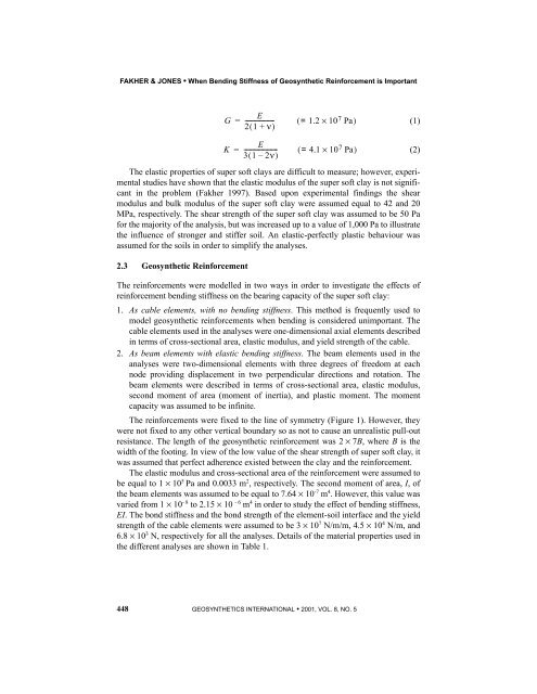
G<br />
E<br />
= ------------------- ( = 1.2 × 10<br />
21 ( + ν)<br />
7 Pa)<br />
(1)<br />
E<br />
K = ---------------------- ( = 4.1 × 10 (2)<br />
31 ( – 2ν)<br />
7 Pa)<br />
The elastic properties of super soft clays are difficult to measure; however, experimental<br />
studies have shown that the elastic modulus of the super soft clay is not significant<br />
in the problem (<strong>Fakher</strong> 1997). Based upon experimental findings the shear<br />
modulus <strong>and</strong> bulk modulus of the super soft clay were assumed equal to 42 <strong>and</strong> 20<br />
MPa, respectively. The shear strength of the super soft clay was assumed to be 50 Pa<br />
for the majority of the analysis, but was increased up to a value of 1,000 Pa to illustrate<br />
the influence of stronger <strong>and</strong> stiffer soil. An elastic-perfectly plastic behaviour was<br />
assumed for the soils in order to simplify the analyses.<br />
2.3 Geosynthetic Reinforcement<br />
The reinforcements were modelled in two ways in order to investigate the effects of<br />
reinforcement bending stiffness on the bearing capacity of the super soft clay:<br />
1. As cable elements, with no bending stiffness. This method is frequently used to<br />
model geosynthetic reinforcements when bending is considered unimportant. The<br />
cable elements used in the analyses were one-dimensional axial elements described<br />
in terms of cross-sectional area, elastic modulus, <strong>and</strong> yield strength of the cable.<br />
2. As beam elements with elastic bending stiffness. The beam elements used in the<br />
analyses were two-dimensional elements with three degrees of freedom at each<br />
node providing displacement in two perpendicular directions <strong>and</strong> rotation. The<br />
beam elements were described in terms of cross-sectional area, elastic modulus,<br />
second moment of area (moment of inertia), <strong>and</strong> plastic moment. The moment<br />
capacity was assumed to be infinite.<br />
The reinforcements were fixed to the line of symmetry (Figure 1). However, they<br />
were not fixed to any other vertical boundary so as not to cause an unrealistic pull-out<br />
resistance. The length of the geosynthetic reinforcement was 2 × 7B, where B is the<br />
width of the footing. In view of the low value of the shear strength of super soft clay, it<br />
was assumed that perfect adherence existed between the clay <strong>and</strong> the reinforcement.<br />
The elastic modulus <strong>and</strong> cross-sectional area of the reinforcement were assumed to<br />
be equal to 1 × 10 5 Pa <strong>and</strong> 0.0033 m 2 , respectively. The second moment of area, I, of<br />
the beam elements was assumed to be equal to 7.64 × 10 -7 m 4 . However, this value was<br />
varied from 1 × 10 - 8 to 2.15 × 10 - 6 m 4 in order to study the effect of bending stiffness,<br />
EI. The bond stiffness <strong>and</strong> the bond strength of the element-soil interface <strong>and</strong> the yield<br />
strength of the cable elements were assumed to be 3 × 10 7 N/m/m, 4.5 × 10 4 N/m, <strong>and</strong><br />
6.8 × 10 3 N, respectively for all the analyses. Details of the material properties used in<br />
the different analyses are shown in Table 1.<br />
448 GEOSYN<strong>THE</strong>TICS INTERNATIONAL • 2001, VOL. 8, NO. 5


