

Technical Paper by A. Fakher and C.J.F.P. Jones WHEN THE ...
Technical Paper by A. Fakher and C.J.F.P. Jones WHEN THE ...
Technical Paper by A. Fakher and C.J.F.P. Jones WHEN THE ...

You also want an ePaper? Increase the reach of your titles
YUMPU automatically turns print PDFs into web optimized ePapers that Google loves.
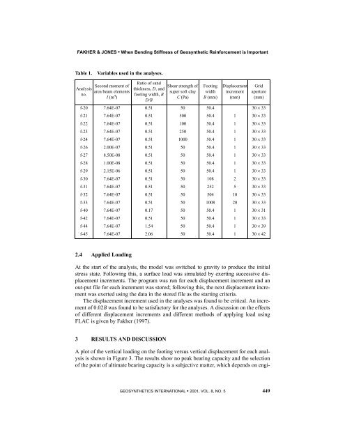
FAKHER & JONES • When Bending Stiffness of Geosynthetic Reinforcement is Important<br />
Table 1.<br />
Variables used in the analyses.<br />
Analysis<br />
no.<br />
Second moment of<br />
area beam elements<br />
I (m 4 )<br />
Ratio of s<strong>and</strong><br />
thickness, D, <strong>and</strong><br />
footing width, B<br />
D/B<br />
Shear strength of<br />
super soft clay<br />
C (Pa)<br />
Footing<br />
width<br />
B (mm)<br />
Displacement<br />
increment<br />
(mm)<br />
Grid<br />
aperture<br />
(mm)<br />
f-20 7.64E-07 0.51 50 50.4 30 × 33<br />
f-21 7.64E-07 0.51 500 50.4 1 30 × 33<br />
f-22 7.64E-07 0.51 100 50.4 1 30 × 33<br />
f-23 7.64E-07 0.51 250 50.4 1 30 × 33<br />
f-24 7.64E-07 0.51 1000 50.4 1 30 × 33<br />
f-26 2.00E-07 0.51 50 50.4 1 30 × 33<br />
f-27 8.50E-08 0.51 50 50.4 1 30 × 33<br />
f-28 1.00E-08 0.51 50 50.4 1 30 × 33<br />
f-29 2.15E-06 0.51 50 50.4 1 30 × 33<br />
f-30 7.64E-07 0.51 50 108 2 30 × 33<br />
f-31 7.64E-07 0.51 50 252 5 30 × 33<br />
f-32 7.64E-07 0.51 50 504 10 30 × 33<br />
f-33 7.64E-07 0.51 50 1008 20 30 × 33<br />
f-40 7.64E-07 0.17 50 50.4 1 30 × 31<br />
f-42 7.64E-07 0.51 50 50.4 1 30 × 33<br />
f-44 7.64E-07 1.54 50 50.4 1 30 × 39<br />
f-45 7.64E-07 2.06 50 50.4 1 30 × 42<br />
2.4 Applied Loading<br />
At the start of the analysis, the model was switched to gravity to produce the initial<br />
stress state. Following this, a surface load was simulated <strong>by</strong> exerting successive displacement<br />
increments. The program was run for each displacement increment <strong>and</strong> an<br />
out-put file for each increment was stored; following this, the next displacement increment<br />
was exerted using the data in the stored file as the starting criteria.<br />
The displacement increment used in the analyses was found to be critical. An increment<br />
of 0.02B was found to be satisfactory for the analyses. A discussion on the effects<br />
of different displacement increments <strong>and</strong> different methods of applying load using<br />
FLAC is given <strong>by</strong> <strong>Fakher</strong> (1997).<br />
3 RESULTS AND DISCUSSION<br />
A plot of the vertical loading on the footing versus vertical displacement for each analysis<br />
is shown in Figure 3. The results show no peak bearing capacity <strong>and</strong> the selection<br />
of the point of ultimate bearing capacity is a subjective matter, which depends on engi-<br />
GEOSYN<strong>THE</strong>TICS INTERNATIONAL • 2001, VOL. 8, NO. 5 449


