You also want an ePaper? Increase the reach of your titles
YUMPU automatically turns print PDFs into web optimized ePapers that Google loves.
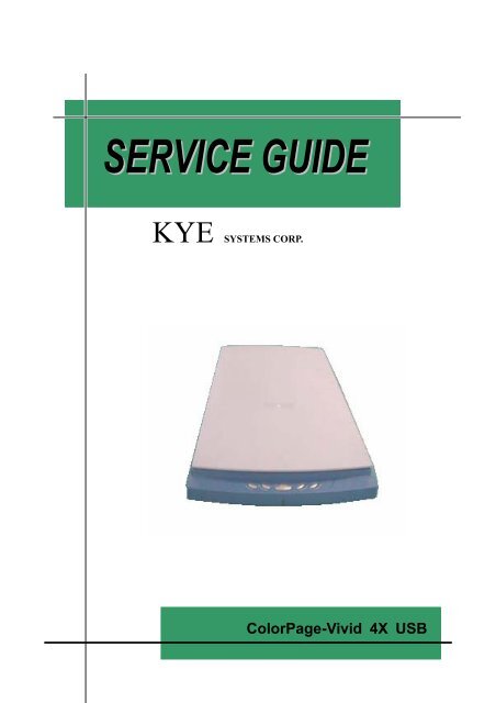
KYE SYSTEMS CORP.<br />
<strong>ColorPage</strong>-<strong>Vivid</strong> <strong>4X</strong> <strong>USB</strong>
Service<br />
Guide<br />
Table of Contents<br />
<strong>ColorPage</strong>-<strong>Vivid</strong> <strong>4X</strong> <strong>USB</strong><br />
Chapter 1. How to Handle Defective Returns ................................................................................................................ 3<br />
Overview ........................................................................................................................................................................ 3<br />
Problems ........................................................................................................................................................................ 4<br />
Problems Descriptions .............................................................................................................................................. 4<br />
Solutions of the problems.......................................................................................................................................... 4<br />
Chapter 2. Assembly and Disassembly............................................................................................................................ 7<br />
How to Assembly and Disassembly the Scanner............................................................................................................ 7<br />
How to Unlock the Lock Key ................................................................................................................................... 7<br />
How to Remove the Upper Cover ............................................................................................................................. 8<br />
How to Remove the Function Button Cable Set ..................................................................................................... 10<br />
How to remove the Sliding Axle and the Timing Belt ............................................................................................ 11<br />
How to Replace the Motor ...................................................................................................................................... 12<br />
How to Replace the Gear Wheel ............................................................................................................................. 13<br />
How to replace the Scan board................................................................................................................................ 13<br />
How to Replace the CCD Board ............................................................................................................................. 14<br />
How to Replace the FFC Cable............................................................................................................................... 15<br />
How to Replace the Lamp....................................................................................................................................... 16<br />
How to Replace the Mirrors.................................................................................................................................... 17<br />
How to Replace the Lens ........................................................................................................................................ 19<br />
Chapter 3. How to Adjust CCD Resolution and Pixels................................................................................................ 20<br />
Adjustment Flows......................................................................................................................................................... 20<br />
Introduction of Facilities and Tools ............................................................................................................................. 21<br />
Adjustment Procedures ................................................................................................................................................ 22<br />
How to Adjust the Lens Resolution......................................................................................................................... 22<br />
How to Adjust the CCD Points & Center Value...................................................................................................... 23<br />
Chapter 4. Important Notes........................................................................................................................................... 24<br />
Packing requirement for sending the PCB assembly ................................................................................................... 24<br />
Short of spare parts while repairing a scanner............................................................................................................ 24<br />
2
Chapter 1.<br />
How to Handle Defective Returns<br />
Overview<br />
Receiving Defective<br />
Scanners<br />
from Customers<br />
Verifying problems &<br />
poceeding necessary tests<br />
Functioning NG<br />
Analyzing possible<br />
malfunction causes<br />
Functioning NG<br />
Deciding & proceeding<br />
the rectification methods<br />
Replacing necessary<br />
defective parts<br />
Functioning OK<br />
Proceeding tests<br />
to verify if the scanner is<br />
founctioning normally<br />
Functioning OK<br />
Return the scanners with<br />
proper repackaging to customers
Service<br />
Guide<br />
<strong>ColorPage</strong>-<strong>Vivid</strong> <strong>4X</strong> <strong>USB</strong><br />
Problems<br />
Problems Descriptions<br />
1 Main lamp unilluminated<br />
2 No Scan (Including: Scanner not functioning or fail to activate TWAIN<br />
program, etc..)<br />
3 Bad Motor<br />
4 Poor Scanning Image<br />
5 Others ( such as the Broken of the Defection Mirror or the Broken of the<br />
Document Glass, etc..)<br />
Solutions of the problems<br />
• Main lamp unilluminated<br />
Problem<br />
Main lamp unilluminated<br />
Analyze the<br />
Mechanical<br />
Electronic<br />
Problem<br />
Identify the<br />
Problem Causes<br />
Broken or<br />
Defective Lamp<br />
Burned out or<br />
Defective Inverter<br />
Defective<br />
Scan Board<br />
Defective<br />
CCD Board<br />
Solutions<br />
Replace<br />
Replace<br />
Replace<br />
Replace<br />
Lamp<br />
Inverter<br />
Scan Board<br />
CCD Board<br />
4
Service<br />
Guide<br />
<strong>ColorPage</strong>-<strong>Vivid</strong> <strong>4X</strong> <strong>USB</strong><br />
• No Scan (including: Scanner not functioning, or fail to activate TWAIN Program, etc..)<br />
Problem<br />
No Scan<br />
Analyze the<br />
Problem<br />
Scan Board<br />
CCD Board<br />
Identify the<br />
Problem Causes<br />
Defective<br />
Scan Board<br />
Defective<br />
CCD Board<br />
Solutions<br />
Replace<br />
Scan Board<br />
Replace<br />
CCD Board<br />
• Bad Motor Driving<br />
Problem<br />
Bad Motor Driving<br />
Analyze the<br />
Problem<br />
Scan Board<br />
Motor<br />
Mechanical<br />
Identify the<br />
Problem Causes<br />
Defective<br />
Scan Board<br />
Defective<br />
Motor<br />
Upper Housing,<br />
Base Housing, or<br />
Belt is not in the<br />
right position<br />
Defective<br />
Gear<br />
Solutions<br />
Replace<br />
Scan Board<br />
Replace<br />
Motor<br />
Re-install Upper<br />
Housing, Base<br />
Housing, or Belt<br />
Replace<br />
Gear<br />
5
Service<br />
Guide<br />
<strong>ColorPage</strong>-<strong>Vivid</strong> <strong>4X</strong> <strong>USB</strong><br />
• Poor Scanning Image<br />
Problem<br />
Poor Scanning Image<br />
Analyze the<br />
Problem<br />
Electronic<br />
Mechanical<br />
Identify the<br />
Problem Causes<br />
Defective<br />
CCD Board<br />
Defective<br />
Scan Board<br />
Incorrect<br />
CCD Focus<br />
Defective<br />
Reflection<br />
Mirror<br />
Solutions<br />
Replace<br />
CCD Board<br />
Replace<br />
Scan Board<br />
Re-adjust<br />
CCD Pixels<br />
Replace<br />
Reflection<br />
Mirror<br />
• Others<br />
There are some other problems, such as Broken of the Reflection Mirror and the<br />
Document Glass, etc.. Please refer to the related chapters for solving these problems.<br />
6
Service<br />
Guide<br />
<strong>ColorPage</strong>-<strong>Vivid</strong> <strong>4X</strong> <strong>USB</strong><br />
Chapter 2.<br />
Assembly and Disassembly<br />
How to Assembly and Disassembly the Scanner<br />
How to Unlock the Lock Key<br />
magnifier<br />
figure 2.1.1. figure 2.1.2.<br />
This scanner has a locking mechanism to hold the Scanner Module in place during<br />
transportation. The Auto Lock Key is located on the base of the scanner. Turn over the<br />
Scanner, then you can see the Auto Lock Key (figure 2.1.2).<br />
Before using the Scanner, please make sure the scanner to put on the solid & flat table ,<br />
then Auto Lock Key will be unlock status. If not, the Scanner can’t function correctly.<br />
Besides, if user move the scanner after the Reflection Mirror has go back to the Start, then<br />
Auto Lock Key will be lock status. This will ensure accurate and problem-free use of the<br />
scanner.<br />
7
Service<br />
Guide<br />
<strong>ColorPage</strong>-<strong>Vivid</strong> <strong>4X</strong> <strong>USB</strong><br />
How to Remove the Upper Cover<br />
• How to Disassembly the Scanner<br />
Step 1<br />
We will find a mortise-like and a tenon-like<br />
device, which fasten up the top cover and the base<br />
frame.<br />
figure 2.2.1.<br />
Step 2<br />
Use fingers to exert to turn outside on the<br />
buttons, open tenon-like of top cover, then you can<br />
open the top cover.<br />
figure 2.2.2.<br />
8
Service<br />
Guide<br />
<strong>ColorPage</strong>-<strong>Vivid</strong> <strong>4X</strong> <strong>USB</strong><br />
• How to Remove the Document Glass<br />
Step 1<br />
Please remove four Glass Stop Blocks shown<br />
below a & b 2 arrow points first.<br />
figure 2.3.1.<br />
Step 2<br />
figure 2.3.2.<br />
With a screwdriver, press down the left end of<br />
the Glass Stop Block, and then push it to the right.<br />
Then, you may take the Glass Stop Block out of the<br />
glass holder, and release the space between the<br />
edge of the Document Glass and the Upper<br />
Housing.<br />
Step 3<br />
After the Glass Stop Block is removed, turn<br />
the Document Glass upside down to let it drop into<br />
the space between the edge of the Document Glass<br />
and the top cover as mentioned in step 2.<br />
figure 2.3.3.<br />
Step 4<br />
Erect the Document Glass as shown in figure<br />
2.3.4. , and take out the Document Glass gently.<br />
figure 2.3.4.<br />
★To install the Document Glass, reverse the steps shown above. ★<br />
9
Service<br />
Guide<br />
<strong>ColorPage</strong>-<strong>Vivid</strong> <strong>4X</strong> <strong>USB</strong><br />
How to Remove the Function Button Cable Set<br />
Step 1<br />
Loosen the screw on the Switch Board.<br />
figure 2.4.1.<br />
Button Line<br />
Step 2<br />
Disconnect the Cable connecter that is<br />
connected to the Scan Board.<br />
Pull up the cable then you can change<br />
Switch Board or Button Line.<br />
FFC Cable<br />
figure 2.4.2.<br />
★ To install the Function Button Cable Set, reverse the steps shown above. ★<br />
10
Service<br />
Guide<br />
<strong>ColorPage</strong>-<strong>Vivid</strong> <strong>4X</strong> <strong>USB</strong><br />
How to remove the Sliding Axle and the Timing Belt<br />
Step 1<br />
Hold the Sliding Axle & take out the Sliding Axle<br />
from the module so lightly.<br />
figure 2.5.1.<br />
Step 2<br />
Move the module to the middle of the base frame.<br />
Take out the Sliding Axle from the module so lightly.<br />
figure 2.5.2.<br />
Step 3<br />
Hold on the Timing Belt, and turn the spring .<br />
Take off the other end by the same way, then you can<br />
easily take off the Timing Belt from the Gear Wheel.<br />
figure 2.5.3.<br />
Step 4<br />
To replace the Timing Belt, place alcohol in drops<br />
once every 3~5 minutes and repeat 2~3 times to dissolve<br />
green seal. After green seal was completely dissolved,<br />
and then you may use a tweezers to take off the Timing<br />
Belt from Module.<br />
figure 2.5.4.<br />
11
Service<br />
Guide<br />
<strong>ColorPage</strong>-<strong>Vivid</strong> <strong>4X</strong> <strong>USB</strong><br />
Magnify the point of Belt-fixed (A)<br />
Timing Belt<br />
To install the Sliding Axle and the Timing Belt,<br />
reverse the steps shown above.<br />
Inside of<br />
belt-fixed<br />
point (A)<br />
Outside of<br />
belt-fixed<br />
point (A)<br />
Notice: Ensure that the Timing Belt is installed with the<br />
correct direction as shown in figure 2.5.5.<br />
figure 2.5.5.<br />
How to Replace the Motor<br />
Step 1<br />
Dissolve the green seal on the screws..<br />
Loosen the screws from fixed plate of idle arm<br />
with a screwdriver.<br />
figure 2.6.1.<br />
Step 2<br />
Disconnect the connector of the Motor that is<br />
connected to the Scan Board. Then , take off the<br />
Motor.<br />
figure 2.6.2.<br />
Step 3<br />
Motor wire fixed method shown as figure 2.6.3.<br />
Motor Line<br />
figure 2.6.3.<br />
★ To install the Motor, reverse the steps shown above. ★<br />
Notice: When installing the Motor, please do not turn the screw too tight. And don’t forget to<br />
use the green seal to fix the screw.<br />
12
Service<br />
Guide<br />
<strong>ColorPage</strong>-<strong>Vivid</strong> <strong>4X</strong> <strong>USB</strong><br />
How to Replace the Gear Wheel<br />
Step 1<br />
To remove the Gear Wheel, take out the E Ring (refer to<br />
figure 2.7.1.) with a tweezers.<br />
When installing, please install the Gear Wheel, and then<br />
using the Nipper to put the E Ring back.<br />
figure2.7.1.<br />
Notice: When taking out the E Ring, please be careful not<br />
to let it gone.<br />
figure 2.7.2.<br />
How to replace the Scan board<br />
Motor Connector<br />
Button Connector<br />
Button Line<br />
FFC Cable<br />
FFC Cable<br />
figure 2.8.1.<br />
Step 1<br />
Before gentle pull up the scan board from the slot on<br />
the button case, disconnect the cable of FFC, motor cable<br />
and function button cable.<br />
Step 2<br />
Before install the Scan board back , the FCC cable<br />
should pass under through the EMI core and white PAD and<br />
connect to the Scan board, then connect the motor cable.<br />
Notice: To change the FFC cable , please refer to<br />
“How to Replace the FFC Cable “<br />
figure 2.8.2.<br />
13
Service<br />
Guide<br />
<strong>ColorPage</strong>-<strong>Vivid</strong> <strong>4X</strong> <strong>USB</strong><br />
How to Replace the CCD Board<br />
Step 1<br />
Disconnect the FFC Cable.<br />
figure 2.9.1.<br />
Step 2<br />
Dissolve the green seal on the screws on the scan<br />
board before you loosen them.<br />
figure 2.9.2.<br />
Inverter Connector<br />
Lamp Connector<br />
Screw<br />
figure 2.9.3.<br />
Step 3<br />
Disconnect the connector of Inverter, then you can<br />
take off the CCD Board.<br />
Notice: To Install or adjust the CCD Board, please<br />
refer to the chapter 3: How to Adjust the CCD<br />
Board.<br />
14
Service<br />
Guide<br />
<strong>ColorPage</strong>-<strong>Vivid</strong> <strong>4X</strong> <strong>USB</strong><br />
How to Replace the FFC Cable<br />
Step 1<br />
Pull out one end of the FFC Cable, which is<br />
attached to the Scan Board.<br />
figure 2.10.1.<br />
Notice: While pulling out the FFC Cable,<br />
make sure that it is pull out with<br />
steady strength, otherwise, you may<br />
bend the FFC Cable, and result<br />
system failure.<br />
Step 2<br />
Pull out another end of the FFC Cable,<br />
which is attached to the CCD Board.<br />
figure 2.10. 2.<br />
Front Side<br />
Step 3<br />
figure 2.10. 3.<br />
When installing the FFC Cable, ensure that<br />
both connecting side on the FFC Cable (shown<br />
in figure 2.10.3.) and Scan Board or CCD Board<br />
(shown in figure 2.10.4.) must face each other,<br />
otherwise, it may result system failure.<br />
Reverse Side<br />
Step 4<br />
Reverse the steps shown above to install the<br />
FFC cable.<br />
figure 2.10. 4.<br />
Front Side<br />
Step 5<br />
figure 2.10.5.<br />
Notice: To connect the cable to the slot and<br />
to prevent the scanner from losing<br />
signal which will cause the IC<br />
burnout on the scanner board ,<br />
please make sure that the<br />
connection is perfect.<br />
15
Service<br />
Guide<br />
<strong>ColorPage</strong>-<strong>Vivid</strong> <strong>4X</strong> <strong>USB</strong><br />
How to Replace the Lamp<br />
Step 1<br />
Inverter<br />
Disconnect the CCD Connector that is attached to the<br />
CCD Board. Loosen the screw, then you can take off the<br />
Inverter.<br />
Disconnect the Lamp Connector that is attached to<br />
the Inverter.<br />
figure 2.11.1.<br />
Notice: Lamps are fragile and could break, please<br />
pay more attention while replacing them.<br />
Step 2<br />
Pull out the Lamp wire gently.<br />
figure2.11.2.<br />
Step 3<br />
Pull out one end of the Lamp where a protection<br />
rubber is covered, and then the other end.<br />
figure 2.11.3.<br />
16
Service<br />
Guide<br />
<strong>ColorPage</strong>-<strong>Vivid</strong> <strong>4X</strong> <strong>USB</strong><br />
How to Replace the Mirrors<br />
Step 1<br />
Loosen the 2 pcs screws of module cover with a<br />
screwdriver.<br />
figure 2.12.1.<br />
Step 2<br />
Exert to push forward , then you can take apart the<br />
module cover.<br />
figure2.12.2.<br />
Module Cover<br />
Step 3<br />
You can see module cover & module.<br />
Module Assembly<br />
figure 2.12.3.<br />
Step 4<br />
Module process from 5pcs glass to combine.<br />
figure 2.12.4.<br />
17
Service<br />
Guide<br />
<strong>ColorPage</strong>-<strong>Vivid</strong> <strong>4X</strong> <strong>USB</strong><br />
Step 5<br />
After remove the black seal, the five mirrors can be<br />
seen in the Scanner Module.<br />
Mirror A,B,C, D ,E are all fixed in mirror fix clips<br />
with black seal.<br />
figure 2.12.5.<br />
Step 6<br />
Before removing these Mirrors, dissolve black seal<br />
with alcohol first and take out the mirror fix clips by<br />
tweezers.<br />
figure 2.12.6.<br />
Step 7<br />
figure 2.12.7.<br />
When installing Mirrors, use one hand to insert the<br />
mirror into the position that it belongs to, and the other<br />
hand to hold the module and prevent the mirror from<br />
falling down from the groove on the module.<br />
Notice:<br />
1. Please be noted that the mirror fix clips must be<br />
inserted with a proper direction.<br />
figure 2.12.8.<br />
2. To install the mirrors, ensure that the reflection<br />
side must face inward of the scanner module<br />
Reflection side<br />
Non-reflection side<br />
18
Service<br />
Guide<br />
<strong>ColorPage</strong>-<strong>Vivid</strong> <strong>4X</strong> <strong>USB</strong><br />
How to Replace the Lens<br />
Screws<br />
Step 1<br />
Need to loosen the 2 pcs screws, then you can open<br />
the lens cover.<br />
figure 2.13.1.<br />
Step 2<br />
Loosen the 2 pcs screws of lens cover with a<br />
screwdriver.<br />
figure2.13.2.<br />
Lens<br />
Step 3<br />
You can replace or adjust lens.<br />
About lens adjust refer to chapter 3 please, shown<br />
below.<br />
figure 2.13.3.<br />
19
Service<br />
Guide<br />
<strong>ColorPage</strong>-<strong>Vivid</strong> <strong>4X</strong> <strong>USB</strong><br />
Chapter 3.<br />
How to Adjust CCD Resolution<br />
and Pixels<br />
Adjustment Flows<br />
• Operation Flow<br />
Start<br />
Module Installation<br />
Preparation<br />
Formation Adjustment<br />
Scanner Center & Step’s<br />
Adjustment<br />
Adjustment Completed Module<br />
Finish<br />
20
Service<br />
Guide<br />
<strong>ColorPage</strong>-<strong>Vivid</strong> <strong>4X</strong> <strong>USB</strong><br />
Introduction of Facilities and Tools<br />
Facilities:<br />
1. Computer<br />
2. CCD Adjustment Software<br />
figure 3.1.1.<br />
figure 3.1.2.<br />
Tools:<br />
1. Module Horizontal Resolution<br />
*2(600dpi;1200dpi)<br />
2. Screwdriver (Cross type) *1<br />
3. Green Seal *1<br />
4. Torsional Driver *2<br />
5. Tweezers *2<br />
6. Nippers *2<br />
21
Service<br />
Guide<br />
<strong>ColorPage</strong>-<strong>Vivid</strong> <strong>4X</strong> <strong>USB</strong><br />
Adjustment Procedures<br />
How to Adjust the Lens Resolution<br />
Step 1<br />
1. Connecting the scanner to the computer. And<br />
activating the adjustment program according to<br />
the model you want to repair. ( refer to figure<br />
12.1)<br />
figure 3.2.1.<br />
2. Reset the system before proceeding any<br />
adjustment.<br />
figure 3.2.2.<br />
(Adjustment Screen)<br />
Step 2<br />
1. Place the Scanner Module on a Module<br />
Horizontal Resolution Adjustment tool.<br />
2. Loosen the screws then adjust lens resolution of<br />
the front and rear use the tweezers.<br />
figure 3.2.3.<br />
Step 3<br />
1. Slightly adjust the position of lens till the<br />
waveform shown in the computer screen has<br />
reached its maximum wavelength.<br />
figure 3.2.4.<br />
2. Fasten the screws , then place green seal onto<br />
the screws.<br />
22
Service<br />
Guide<br />
<strong>ColorPage</strong>-<strong>Vivid</strong> <strong>4X</strong> <strong>USB</strong><br />
How to Adjust the CCD Points & Center Value<br />
Step 1<br />
1. Loosen the screws that adjust the CCD Board.<br />
2. With one hand to adjust the Scanner Center<br />
slightly to the right or left.<br />
3. After the Scanner Center is set, hold the CCD<br />
Board with one hand, and then adjust the CCD<br />
points slightly up or down.<br />
figure 3.3.1.<br />
4. When adjustments have been done, and then<br />
you may solidly fasten the screws.<br />
Notice:<br />
A. The Scanner Center value for the Module<br />
Horizontal Resolution Adjustment tool is<br />
between +10 to -10).<br />
B. The CCD points value for the Module<br />
Horizontal Resolution Adjustment tool is<br />
between 3 ±1).<br />
Step 2<br />
1. Slightly adjust the position of CCD Board till<br />
the waveform shown in the computer screen has<br />
reached its maximum wavelength.<br />
figure 3.3.2.<br />
2. Fasten the screws temporarily, but do not solidly<br />
fasten the screws.<br />
Step 3<br />
1. Fasten the screws , then place green seal onto<br />
the screws.<br />
2. Re-install the Scanner Module back to its<br />
original position.<br />
figure 3.3.3.<br />
23
Service<br />
Guide<br />
<strong>ColorPage</strong>-<strong>Vivid</strong> <strong>4X</strong> <strong>USB</strong><br />
Chapter 4.<br />
Important Notes<br />
Packing requirement for sending the PCB assembly<br />
PCB assembly is a kind of sophisticated electronic circuit board. A scanner mainly includes<br />
the following items: Scan Board, CCD Board, Switch Board, Panel Board, etc.. Therefore,<br />
well packing will be required when sending them by post or courier.<br />
1. Some sophisticated IC components are mounted on the PCB assembly, hence it is necessary to<br />
pack each PCB assembly with a separate static protecting beg, in order to avoid static<br />
electricity.<br />
2. CCD sensor is the most important component on the CCD Board, hence, CCD sensor must be<br />
covered by a protecting sheet (shown as below) when mailing it, in order to prevent from<br />
scratch.<br />
CCD sensor, covered by a screen<br />
protecting sheet<br />
3. Reliable external packing is also very important when sending the PCB assembly by post, in<br />
that it would avoid unnecessarily lost or damage.<br />
Short of spare parts while repairing a scanner<br />
If you are short of spare parts when you have some scanners waiting to be repaired, it would be<br />
recommended to take the necessary parts from one scanner, so that you may have the as many<br />
as scanners be repaired and sent back to your customer, and left only one or few scanners<br />
waiting for spare parts sending from KYE.<br />
24


