AUTOFLEX - Autogard Kupplungen Gmbh
AUTOFLEX - Autogard Kupplungen Gmbh
AUTOFLEX - Autogard Kupplungen Gmbh

Create successful ePaper yourself
Turn your PDF publications into a flip-book with our unique Google optimized e-Paper software.
4<br />
<strong>AUTOFLEX</strong> METAL MEMBRANE COUPLINGS<br />
Coupling Selection<br />
Method<br />
Data required for Coupling Selection.<br />
• Application details (for service factor)<br />
• Power and rpm of the driver<br />
• Shaft details of the driving and driven equipment<br />
(1) Determine the service factor (SF) from the application<br />
and classification lists noted below.<br />
(2) Calculate the maximum kW/1000 rpm rating:<br />
kW/1000rpm = (kW x 1000 x SF) / rpm<br />
Select the coupling which has a higher max rating.<br />
(3) Check the Limiting Conditions:<br />
a Check the hub bore capacity is suitable<br />
b Check the speed capability and specify whether<br />
the coupling requires balancing.<br />
c Check coupling dimensions such as DBSE*,<br />
Overall Length and Outside Diameter.<br />
*DBSE - Distance Between Shaft Ends<br />
Service Factors - SF<br />
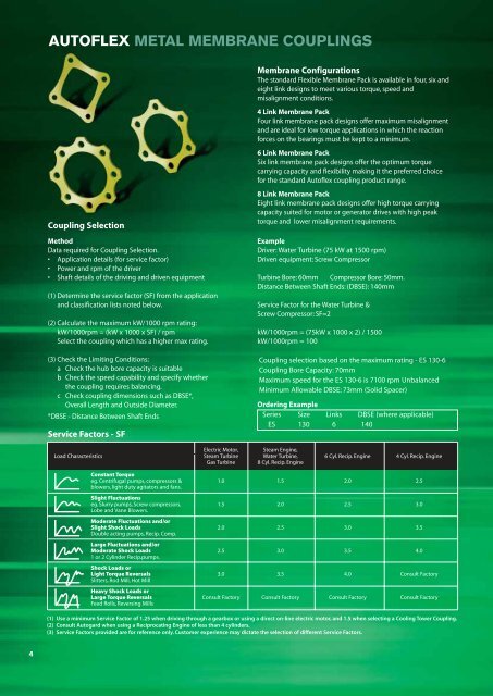
Membrane Configurations<br />
The standard Flexible Membrane Pack is available in four, six and<br />
eight link designs to meet various torque, speed and<br />
misalignment conditions.<br />
4 Link Membrane Pack<br />
Four link membrane pack designs offer maximum misalignment<br />
and are ideal for low torque applications in which the reaction<br />
forces on the bearings must be kept to a minimum.<br />
6 Link Membrane Pack<br />
Six link membrane pack designs offer the optimum torque<br />
carrying capacity and flexibility making it the preferred choice<br />
for the standard Autoflex coupling product range.<br />
8 Link Membrane Pack<br />
Eight link membrane pack designs offer high torque carrying<br />
capacity suited for motor or generator drives with high peak<br />
torque and lower misalignment requirements.<br />
Example<br />
Driver: Water Turbine (75 kW at 1500 rpm)<br />
Driven equipment: Screw Compressor<br />
Turbine Bore: 60mm Compressor Bore: 50mm.<br />
Distance Between Shaft Ends: (DBSE): 140mm<br />
Service Factor for the Water Turbine &<br />
Screw Compressor: SF=2<br />
kW/1000rpm = (75kW x 1000 x 2) / 1500<br />
kW/1000rpm = 100<br />
Coupling selection based on the maximum rating - ES 130-6<br />
Coupling Bore Capacity: 70mm<br />
Maximum speed for the ES 130-6 is 7100 rpm Unbalanced<br />
Minimum Allowable DBSE: 73mm (Solid Spacer)<br />
Ordering Example<br />
Series Size Links DBSE (where applicable)<br />
ES 130 6 140<br />
Electric Motor, Steam Engine,<br />
Load Characteristics Steam Turbine Water Turbine, 6 Cyl. Recip. Engine 4 Cyl. Recip. Engine<br />
Gas Turbine 8 Cyl. Recip. Engine<br />
Constant Torque<br />
eg. Centrifugal pumps, compressors &<br />
blowers, light duty agitators and fans.<br />
Slight Fluctuations<br />
1.0 1.5 2.0 2.5<br />
eg. Slurry pumps, Screw compressors,<br />
Lobe and Vane Blowers.<br />
Moderate Fluctuations and/or<br />
1.5 2.0 2.5 3.0<br />
Slight Shock Loads<br />
Double acting pumps, Recip. Comp.<br />
Large Fluctuations and/or<br />
2.0 2.5 3.0 3.5<br />
Moderate Shock Loads<br />
1 or 2 Cylinder Recip.pumps.<br />
Shock Loads or<br />
2.5 3.0 3.5 4.0<br />
Light Torque Reversals<br />
Slitters, Rod Mill, Hot Mill<br />
Heavy Shock Loads or<br />
3.0 3.5 4.0 Consult Factory<br />
Large Torque Reversals<br />
Feed Rolls, Reversing Mills<br />
Consult Factory Consult Factory Consult Factory Consult Factory<br />
(1) Use a minimum Service Factor of 1.25 when driving through a gearbox or using a direct on-line electric motor, and 1.5 when selecting a Cooling Tower Coupling.<br />
(2) Consult <strong>Autogard</strong> when using a Reciprocating Engine of less than 4 cylinders.<br />
(3) Service Factors provided are for reference only. Customer experience may dictate the selection of different Service Factors.