Table of Contents Section 1 – New and Featured Products
Table of Contents Section 1 – New and Featured Products
Table of Contents Section 1 – New and Featured Products

Create successful ePaper yourself
Turn your PDF publications into a flip-book with our unique Google optimized e-Paper software.
®<br />
Signal Conditioning/Calibration <strong>and</strong> Control <strong>Products</strong><br />
X95310 Digitally Controlled Potentiometer (XDCP )<br />
Product Highlights<br />
• Dual Voltage Supply<br />
• Terminal Voltage 0V to 13V<br />
• 128 Tap<br />
• Up/Down Interface with Chip Select Enable<br />
• Non-volatile Digital Potentiometer<br />
Key Features<br />
• Non-volatile Solid-state Potentiometer<br />
• DCP Terminal voltage, 0 to +13V<br />
• 128 wiper tap points<br />
— Wiper position stored in non-volatile memory<br />
<strong>and</strong> recalled on power-up<br />
• 127 resistive elements<br />
— Temperature compensated<br />
• Low power CMOS<br />
• Endurance, 100,000 data changes per bit<br />
• 10-lead MSOP, FCP (Flip-Chip Package)<br />
Benefits<br />
• Digital Programmability<br />
• Set <strong>and</strong> Forget Calibration<br />
• Reliability<br />
• Dynamic Controls<br />
• Non-volatile storage <strong>and</strong> recall <strong>of</strong> wiper position<br />
• Power On Recall Circuits<br />
• General purpose EEPROM<br />
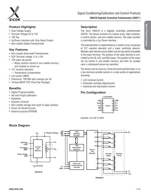
Description<br />
The Xicor X95310 is a digitally controlled potentiometer<br />
(XDCP). The device consists <strong>of</strong> a resistor array, wiper switches,<br />
a control section, <strong>and</strong> non-volatile memory. The wiper position<br />
is controlled by a Up /Down interface.<br />
The potentiometer is implemented by a resistor array composed<br />
<strong>of</strong> 127 resistive elements <strong>and</strong> a wiper switching network.<br />
Between each element <strong>and</strong> at either end are tap points accessible<br />
to the wiper terminal. The position <strong>of</strong> the wiper element is controlled<br />
by the CS, U/D, <strong>and</strong> INC inputs. The position <strong>of</strong> the wiper<br />
can be stored in non-volatile memory <strong>and</strong> then be recalled<br />
upon a subsequent power-up operation.<br />
The device can be used as a three-terminal potentiometer or as<br />
a two-terminal variable resistor in a wide variety <strong>of</strong> applications<br />
including:<br />
• LCD Contrast Control<br />
• Parameter <strong>and</strong> Bias Adjustmentsl<br />
• Industrial <strong>and</strong> Automative Control<br />
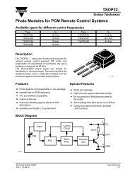
Pin Configuration<br />
U/D<br />
GND<br />
V CC<br />
CS<br />
NC<br />
10-lead MSOP<br />
1<br />
2<br />
3<br />
4<br />
5<br />
10<br />
9<br />
X95310 8<br />
7<br />
6<br />
INC<br />
V+<br />
R L<br />
R W<br />
R H<br />
<strong>New</strong> & <strong>Featured</strong> <strong>Products</strong><br />
Available: 2nd Half <strong>of</strong> 2004<br />
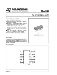
Block Diagram<br />
V CC V+ (Supply Voltage)<br />
U/D<br />
INC<br />
CS<br />
7-Bit<br />
Up/Down<br />
Counter<br />
127<br />
126<br />
R H<br />
Up/Down<br />
(U/D)<br />
Increment<br />
(INC)<br />
Device Select<br />
(CS)<br />
Control<br />
<strong>and</strong><br />
Memory<br />
R H<br />
R W<br />
R L<br />
7-Bit<br />
Nonvolatile<br />
Memory<br />
125<br />
124<br />
One <strong>of</strong><br />
128<br />
Decoder<br />
2<br />
Transfer<br />
Gates<br />
Resistor<br />
Array<br />
V SS<br />
(Ground)<br />
V+<br />
GND<br />
Store <strong>and</strong><br />
Control Recall<br />
Circuitry<br />
1<br />
0<br />
General<br />
R L<br />
R W<br />
Detailed<br />
www.xicor.com<br />
1<strong>–</strong>53