HKTS 7 OM - Harman Kardon
HKTS 7 OM - Harman Kardon
HKTS 7 OM - Harman Kardon

You also want an ePaper? Increase the reach of your titles
YUMPU automatically turns print PDFs into web optimized ePapers that Google loves.
Power for the Digital Revolution. ®<br />
®<br />
<strong>HKTS</strong> 7<br />
H<strong>OM</strong>E THEATER SPEAKER SYSTEM<br />
OWNER’S MANUAL
<strong>HKTS</strong> 7 H<strong>OM</strong>E THEATER SPEAKER SYSTEM<br />
3 Safety Information<br />
4 Introduction<br />
4 Included<br />
5 SUB-TS7 Subwoofer Amplifier Panel Controls and Connections<br />
7 Speaker Placement<br />
7 Color-Coding System<br />
8 Mounting Options<br />
9 Speaker Connections<br />
9 Speaker-Level Connection Guide<br />
10 Dolby Digital or DTS (or Other Digital Surround Mode) Connection<br />
11 Dolby Pro Logic (Non-Digital) – Line Level<br />
12 Dolby Pro Logic (Non-Digital) – Speaker Level<br />
13 Operation<br />
13 Volume<br />
13 Additional Bass Adjustments<br />
14 Troubleshooting<br />
15 Specifications<br />
Typographical Conventions<br />
In order to help you use this manual, certain conventions have been used.<br />
EXAMPLE – (bold type) indicates a specific control or rear-panel connection on the SUB-TS7 subwoofer<br />
EXAMPLE – (OCR type) indicates a control or switch position on the SUB-TS7 subwoofer<br />
¡ – (number in a circle) indicates a rear-panel control or connection on the SUB-TS7 subwoofer<br />
2 TABLE OF CONTENTS
SAFETY INFORMATION<br />
Read First! Important Safety Precautions!<br />
CAUTION<br />
RISK OF ELECTRIC SHOCK<br />
DO NOT OPEN<br />
CAUTION: To prevent electric shock,<br />
do not use this (polarized) <br />
plug with an extension cord, <br />
receptacle or other outlet <br />
unless the blades can <br />
be fully inserted to <br />
prevent blade exposure.<br />
<br />
The lightning flash with arrowhead symbol,<br />
within an equilateral triangle, is intended to<br />
alert the user to the presence of uninsulated<br />
“dangerous voltage” within the product’s<br />
enclosure that may be of sufficient magnitude to constitute a<br />
risk of electric shock to persons.<br />
The exclamation point within an equilateral<br />
triangle is intended to alert the user to the<br />
presence of important operating and<br />
maintenance (servicing) instructions in the<br />
literature accompanying the appliance.<br />
1. Read these instructions.<br />
2. Keep these instructions.<br />
3. Heed all warnings.<br />
4. Follow all instructions.<br />
5. Do not use this apparatus near water.<br />
6. Clean only with a dry cloth.<br />
7. Do not block any ventilation openings. Install in<br />
accordance with the manufacturer’s instructions.<br />
8. Do not install near any heat sources such as radiators,<br />
heat registers, stoves or other apparatus (including<br />
amplifiers) that produce heat.<br />
9. Do not defeat the safety purpose of the polarized<br />
or grounding-type plug. A polarized plug has two<br />
blades with one wider than the other. A groundingtype<br />
plug has two blades and a third grounding<br />
prong. The wide blade or the third prong are provided<br />
for your safety. If the provided plug does not fit into<br />
your outlet, consult an electrician for replacement of<br />
the obsolete outlet.<br />
10. Protect the power cord from being walked on or<br />
pinched, particularly at plugs, convenience receptacles<br />
and the point where they exit from the apparatus.<br />
11. Only use attachments/accessories specified by<br />
the manufacturer.<br />
12. Use only with the cart, stand, tripod,<br />
bracket or table specified by the manufacturer<br />
or sold with the apparatus.<br />
When a cart is used, use caution when<br />
moving the cart/apparatus combination to avoid injury<br />
from tip-over.<br />
13. Unplug this apparatus during lightning storms or<br />
when unused for long periods of time.<br />
14. Refer all servicing to qualified service personnel.<br />
Servicing is required when the apparatus has been<br />
damaged in any way, such as power-supply cord or<br />
plug is damaged, liquid has been spilled or objects<br />
have fallen into the apparatus, the apparatus has been<br />
exposed to rain or moisture, does not operate normally,<br />
or has been dropped.<br />
15. Do not use attachments not recommended by<br />
the product manufacturer, as they may cause hazards.<br />
16. This product should be operated only from the<br />
type of power source indicated on the marking label.<br />
If you are not sure of the type of power supply to<br />
your home, consult your product dealer or local<br />
power company. For products intended to operate<br />
from battery power, or other sources, refer to the<br />
operating instructions.<br />
17. If an outside antenna or cable system is connected<br />
to the product, be sure the antenna or cable system<br />
is grounded so as to provide some protection against<br />
voltage surges and built-up static charges. Article 810<br />
of the National Electrical Code, ANSI/NFPA 70, provides<br />
information with regard to proper grounding<br />
of the mast and supporting structure, grounding of<br />
the lead-in wire to an antenna discharge unit, size<br />
of grounding conductors, location of antennadischarge<br />
unit, connection to grounding electrodes,<br />
and requirements for the grounding electrode.<br />
See Figure 1.<br />
Figure 1.<br />
Example of Antenna Grounding as per<br />
National Electrical Code ANSI/NFPA 70<br />
18. An outside antenna system should not be located<br />
in the vicinity of overhead power lines or other electric<br />
light or power circuits, or where it can fall into such<br />
power lines or circuits. When installing an outside<br />
antenna system, extreme care should be taken to<br />
keep from touching such power lines or circuits, as<br />
contact with them might be fatal.<br />
19. Do not overload wall outlets, extension cords, or<br />
integral convenience receptacles, as this can result in<br />
a risk of fire or electric shock.<br />
20. Never push objects of any kind into this product<br />
through openings, as they may touch dangerous voltage<br />
points or short-out parts that could result in a fire<br />
or electric shock. Never spill liquid of any kind on the<br />
product.<br />
21. Do not attempt to service this product yourself, as<br />
opening or removing covers may expose you to dangerous<br />
voltage or other hazards. Refer all servicing to<br />
qualified service personnel.<br />
22. When replacement parts are required, be sure<br />
the service technician has used replacement parts<br />
specified by the manufacturer or that have the same<br />
characteristics as the original part. Unauthorized substitutions<br />
may result in fire, electric shock or other<br />
hazards.<br />
23. Upon completion of any service or repairs to this<br />
product, ask the service technician to perform safety<br />
checks to determine that the product is in proper<br />
operating condition.<br />
24. The product should be mounted to a wall or<br />
ceiling only as recommended by the manufacturer.<br />
Antenna Lead-In Wire<br />
Ground Clamp<br />
Antenna Discharge Unit (NEC Section 810-20)<br />
Grounding Conductors (NEC Section 810-21)<br />
Electric Service Equipment<br />
Ground Clamps<br />
Power Service Grounding Electrode System<br />
(NEC Art 250, Part H)<br />
SAFETY INFORMATION 3
INTRODUCTION<br />
Introduction<br />
Thank you for purchasing the <strong>Harman</strong> <strong>Kardon</strong><br />
<strong>HKTS</strong> 7, with which you’re about to begin<br />
many years of listening enjoyment. The<br />
<strong>HKTS</strong> 7 has been custom-designed to<br />
provide all the excitement and power of the<br />
cinema experience in your own living room.<br />
While sophisticated electronics and state-ofthe-art<br />
speaker components are hard at work<br />
within the <strong>HKTS</strong> 7, hookup and operation<br />
are simple. Color-keyed cables and connections,<br />
and simple controls make the <strong>HKTS</strong> 7<br />
easy to use.<br />
To obtain maximum enjoyment from your<br />
new home theater speaker system, we urge<br />
you to take a few minutes to read through<br />
this manual. This will ensure that connections<br />
to your receiver or preamp/processor<br />
and amplifier or other external devices are<br />
made properly. In addition, a few minutes<br />
spent learning the functions of the various<br />
controls will enable you to take advantage<br />
of all the power and refinement the <strong>HKTS</strong> 7<br />
is able to deliver.<br />
If you have any questions about this product,<br />
its installation or operation, please<br />
contact your dealer, the best local source<br />
of information.<br />
Description and Features<br />
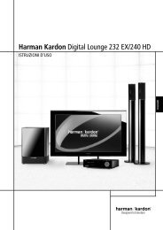
The <strong>HKTS</strong> 7 is a six-piece home theater<br />
speaker system that includes a 10-inch,<br />
100-watt, bass-reflex powered subwoofer;<br />
four identical, 2-way satellite speakers<br />
for use in the left and right front and rear<br />
speaker positions; a voice-matched,<br />
dedicated, dual-driver center speaker; shelf<br />
stands and wall-mount brackets for the<br />
four satellites; and all of the speaker<br />
cables you need to connect your speakers<br />
to your receiver or preamp/processor and<br />
amplifier. The speaker cables and speakers<br />
all use a color-coding system to conform<br />
to the CEA standard. The color-coding<br />
system minimizes confusion, especially<br />
when the <strong>HKTS</strong> 7 system is used with a<br />
<strong>Harman</strong> <strong>Kardon</strong> receiver.<br />
The <strong>HKTS</strong> 7 subwoofer is easy to connect<br />
to your system, since it’s equipped with a<br />
special subwoofer input for use with equipment<br />
that has a dedicated subwoofer connection<br />
that carries a low-frequency output.<br />
It also includes stereo speaker-level inputs<br />
and outputs for connection to older<br />
receivers and processors that do not have<br />
a line-level subwoofer output. Other conveniences<br />
include a level control, high-cut<br />
(low-pass) filter switch and phase switch for<br />
fine-tuning bass response to suit your listening<br />
environment and taste, and an efficient<br />
switching system that senses the presence of<br />
an audio signal and automatically switches<br />
the unit from Standby mode to Active mode.<br />
Shelf stands and wall-mount brackets are<br />
included for the satellite speakers, and<br />
optional HTFS 2 floor stands are available<br />
separately from your <strong>Harman</strong> <strong>Kardon</strong> dealer.<br />
<strong>Harman</strong> <strong>Kardon</strong> invented the high-fidelity<br />
receiver fifty years ago. With state-of-the-art<br />
features and time-honored circuit designs,<br />
the <strong>HKTS</strong> 7 is a perfect complement to<br />
a <strong>Harman</strong> <strong>Kardon</strong> receiver or any home<br />
theater system.<br />
■ Complete home theater speaker<br />
system<br />
■ Speakers are magnetically shielded<br />
for placement near video monitors<br />
■ Fully color-coded cables and<br />
connections simplify setup<br />
■ Both line- and speaker-level inputs<br />
for use with most audio components<br />
■ Subwoofer input offers superiorquality<br />
bass reproduction when used<br />
with any digital audio system that<br />
incorporates bass management or<br />
programmable crossovers<br />
Included<br />
One center channel speaker<br />
Four wall-mount brackets<br />
One powered<br />
subwoofer<br />
Four satellites<br />
for left, right<br />
and surrounds,<br />
with color-key<br />
stickers (shown<br />
with included shelf<br />
stands attached)<br />
One 15' RCA cable for connection to subwoofer<br />
(purple)<br />
Three 20' speaker cables for connection to front<br />
satellites (red and white) and to center<br />
speaker (green)<br />
Two 40' speaker cables for connection from<br />
receiver to rear satellites (gray and blue)<br />
4 INTRODUCTION
SUB-TS7 SUBWOOFER AMPLIFIER PANEL CONTROLS AND CONNECTIONS<br />
¡<br />
<br />
ON<br />
OFF<br />
FILTER<br />
SUBWOOFER<br />
LEVEL<br />
MIN<br />
MAX<br />
SUB-TS7<br />
For use with<br />
<strong>HKTS</strong> 7 System<br />
£<br />
¢<br />
∞<br />
§<br />
LINE<br />
LEVEL<br />
IN<br />
ON<br />
AUTO<br />
SUB<br />
REVERSE<br />
NORMAL<br />
R<br />
PHASE<br />
L<br />
CAUTION<br />
RISK OF ELECTR IC SHO CK<br />
DO NOT OPEN<br />
<br />
H<br />
I<br />
G<br />
H<br />
L<br />
E<br />
V<br />
E<br />
L<br />
L<br />
R<br />
"WARNING: FOR CONTINUED PROTECTION AGAINST RISK OF FIRE,<br />
REPLACE ONLY WITH SAME TYPE T 2.5A L/250 VOLT FUSE"<br />
"AVERTISSEMENT: UTILISEZ UN FUSIBLE DE RECHANGE DE MEME<br />
TYPE T 2.5A L/250V"<br />
POWER<br />
AC 120V~60Hz<br />
•<br />
ª<br />
‚<br />
OUT<br />
IN<br />
IMPORTANT: CONNECT STRIPED WIRE<br />
TO RED ( ) SPEAKER TERMINAL.<br />
¡ Subwoofer-Level Control<br />
High-Cut (Low-Pass) Filter Switch<br />
£ Music-Sense On/Off Switch<br />
¢ Phase Switch<br />
¡ Subwoofer-Level Control: Volume<br />
may be adjusted using the Subwoofer-<br />
Level Control.Turn the control clockwise<br />
to increase the SUB-TS7’s volume, or<br />
counterclockwise to decrease it.<br />
High-Cut (Low-Pass) Filter Switch:<br />
Placing this switch in the ON position activates<br />
circuitry that cuts out all audio input<br />
signals above 120Hz. This allows the SUB-<br />
TS7 to focus its power on reproducing the<br />
low-frequency portion of the signal, avoiding<br />
∞ Line-Level Subwoofer (SUB) Input<br />
§ Line-Level Full-Range Inputs<br />
Speaker-Level Outputs<br />
• Speaker-Level Inputs<br />
inefficiency and distortion. Engage this filter<br />
when using the Speaker-Level Inputs •,<br />
or when using the Line-Level Full-Range<br />
Inputs §, unless your receiver or processor<br />
processes its line-level output using a lowpass<br />
filter. The filter has no effect when the<br />
SUB Input ∞ is used.<br />
£ Music-Sense On/Off Switch: When<br />
placed in the AUTO position, and when the<br />
Master Power Switch ª is turned on, the<br />
SUB-TS7 will automatically turn itself on or<br />
ª Master Power Switch<br />
‚ AC Power Cord<br />
place itself in the Standby mode, depending on<br />
whether it is receiving an audio signal. When<br />
this switch is placed in the ON position, the<br />
SUB-TS7 will remain on, whether or not it is<br />
receiving an audio signal.<br />
An LED located on top of the SUB-TS7 indicates<br />
whether the SUB-TS7 is in the ON or<br />
STANDBY state when used with the Music-<br />
Sense On/Off Switch £ in the AUTO<br />
position. The LED is lit blue to indicate that<br />
the SUB-TS7 is receiving an audio signal<br />
SUB-TS7 SUBWOOFER AMPLIFIER PANEL CONTROLS AND CONNECTIONS 5
SUB-TS7 SUBWOOFER AMPLIFIER PANEL CONTROLS AND CONNECTIONS<br />
and is turned on, and the LED is lit amber to<br />
indicate that no signal is being received and<br />
the SUB-TS7 is in Standby mode.<br />
When the Music-Sense On/Off Switch £<br />
is in the ON position, the LED will be<br />
lit blue, whether or not an audio signal is<br />
present.<br />
When the Master Power Switch ª is<br />
turned off, the LED goes dark, no matter<br />
which position the Music-Sense On/Off<br />
Switch £ is in.<br />
¢ Phase Switch: This switch determines<br />
whether the SUB-TS7 subwoofer’s pistonlike<br />
action moves in and out in phase with<br />
the main speakers. If the speakers were to<br />
play out of phase, the sound waves produced<br />
by the subwoofer would be cancelled<br />
out, reducing bass response. This phenomenon<br />
depends in part on the relative placement<br />
of the speakers in the room. In most<br />
cases, the Phase Switch ¢ should be left<br />
in the NORMAL position. However, it<br />
does no harm to experiment with the Phase<br />
Switch ¢, and you may leave it in the<br />
position that maximizes bass response.<br />
∞ Line-Level Subwoofer (SUB) Input:<br />
Connect the subwoofer output of a receiver<br />
with digital surround sound decoding, such<br />
as Dolby* Digital or DTS ® , to this input. This<br />
input bypasses the SUB-TS7’s internal<br />
crossover circuitry, and should only be used<br />
with a filtered signal. If your receiver does not<br />
have digital decoding, you should use the<br />
Line-Level Full-Range Inputs § instead.<br />
§ Line-Level Full-Range Inputs: Connect<br />
the line-level subwoofer output or preamp output(s)<br />
of your receiver or amplifier to these<br />
inputs. If your receiver does not have a separate<br />
subwoofer output, use a Y-adapter (not<br />
supplied) to bridge the receiver’s preamp output<br />
to the main amp input for that channel,<br />
and connect the long end of the adapter<br />
to the corresponding line-level input on the<br />
SUB-TS7. If your receiver has only a single<br />
subwoofer output, you may connect it to<br />
either the left or right line-level input on the<br />
SUB-TS7, and no Y-adapter is needed.<br />
Speaker-Level Outputs: If you are<br />
using the Speaker-Level Inputs • on the<br />
SUB-TS7, you should connect these bindingpost<br />
terminals to your front left and right<br />
speakers, remembering to maintain polarity<br />
by connecting the (+) terminal on the SUB-<br />
TS7 subwoofer to the (+) terminal on the<br />
speaker, and the (–) terminal on the SUB-<br />
TS7 subwoofer to the (–) terminal on the<br />
speaker. If you are not using the Speaker-<br />
Level Inputs •, then connect your front<br />
left and right speakers directly to your receiver<br />
or amplifier. See pages 9 through 12 for<br />
further information on speaker connections.<br />
• Speaker-Level Inputs: Connect these<br />
binding-post terminals to the main left and<br />
right speaker terminals of your receiver or<br />
amplifier, if your receiver or amplifier does<br />
not have a line-level subwoofer output.<br />
Remember to maintain polarity by connecting<br />
the (+) terminal on the receiver/amplifier to the<br />
(+) terminal on the SUB-TS7 subwoofer, and<br />
the (–) terminal on the receiver/amplifier to the<br />
(–) terminal on the SUB-TS7 subwoofer.<br />
ª Master Power Switch: Place this<br />
switch in the “•” position to power-on the<br />
SUB-TS7 subwoofer. The SUB-TS7 will then<br />
be either in the Standby mode or completely<br />
on, depending on the position of the Music-<br />
Sense On/Off Switch £.<br />
‚ AC Power Cord: Make sure to plug this<br />
cord into an active, unswitched electrical outlet<br />
for proper operation of the SUB-TS7.<br />
The cord should not be plugged into the<br />
accessory outlets found on some audio<br />
components.<br />
6 SUB-TS7 SUBWOOFER AMPLIFIER PANEL CONTROLS AND CONNECTIONS
SPEAKER PLACEMENT<br />
Color-Coding System<br />
The <strong>HKTS</strong> 7 uses the channel color-coding<br />
system established by the Consumer<br />
Electronics Association to make setting up<br />
your home theater speaker system as easy<br />
as possible. Your system includes a set of<br />
colored stickers that may be placed near<br />
the speaker terminals of each of the four<br />
satellite speakers according to the key below.<br />
It doesn’t matter which satellite speaker is<br />
used for any of the front or rear positions.<br />
(The center speaker and powered subwoofer<br />
are already color-coded for you.)<br />
Speaker<br />
Position<br />
Front Left<br />
Front Right<br />
Center<br />
Surround Left<br />
Surround Right<br />
Subwoofer (LFE)<br />
Front Speakers<br />
White<br />
Sticker (or Terminal)<br />
and Cable Color<br />
White<br />
Red<br />
Green<br />
Blue<br />
Gray<br />
Purple<br />
Red<br />
The front speakers should be placed the<br />
same distance from each other as they are<br />
from the listening position. They should be<br />
placed at about the same height from the<br />
floor as the listeners’ ears will be.<br />
Center Channel Speaker<br />
White<br />
The center channel speaker should be<br />
placed slightly behind the front left and right<br />
speakers, and no more than two feet above<br />
or below the tweeters of the left and right<br />
speakers. It is often convenient to set the<br />
center speaker on top of the television set,<br />
as shown in the drawing.<br />
Subwoofer<br />
White<br />
Green<br />
Red 0-2 ft.<br />
Red Purple<br />
The low-frequency material reproduced by<br />
the subwoofer is mostly omnidirectional,<br />
and this speaker may be placed in a convenient<br />
location in the room. However, the<br />
maximum reproduction of bass will be<br />
heard when the subwoofer is placed in a<br />
corner along the same wall as the front<br />
speakers. Experiment with subwoofer placement<br />
by temporarily placing the subwoofer<br />
in the listening position and moving around<br />
the room until the bass reproduction is<br />
best. Place the subwoofer in that location.<br />
Surround Speakers<br />
Blue<br />
White<br />
Green<br />
Red<br />
Gray<br />
5 – 6 ft.<br />
The two surround speakers should be<br />
placed slightly behind the listening position<br />
and, ideally, should face each other and be<br />
at a level higher than the listeners’ ears.<br />
If that is not possible, they may be placed<br />
on a wall behind the listening position,<br />
facing forward. The surround speakers<br />
should not call attention to themselves.<br />
Experiment with their placement until you<br />
hear a diffuse, ambient sound accompanying<br />
the main-program material heard in the<br />
front speakers.<br />
SPEAKER PLACEMENT 7
MOUNTING OPTIONS<br />
Satellites and Surrounds<br />
The satellite speakers may<br />
be placed on a shelf.<br />
They may be wallmounted<br />
using the<br />
supplied brackets.<br />
Wall-Mounting<br />
Unscrew the bolt that attaches the black<br />
shelf stand to the bottom of the speaker.<br />
Store the stand and bolt in a safe place<br />
in case they are needed for a future<br />
installation.<br />
Wires to Speaker<br />
Terminal Cover<br />
Wall Bracket<br />
Wall Plate<br />
Mount the wallbracket<br />
attachment<br />
plate on the wall in<br />
the desired location.<br />
If possible, position<br />
the speakers so that<br />
the mounting screws<br />
15mm<br />
or 1/2"<br />
Remove<br />
Stand<br />
(not included; use size #8) may be<br />
installed directly into a wooden wall stud.<br />
If that is not possible, use optional wall<br />
anchors that are rated to support at least<br />
twenty-five pounds. The customer is<br />
responsible for proper selection and use<br />
of mounting hardware, available through<br />
hardware stores, to properly and safely<br />
wall-mount the speakers.<br />
Referring to the speaker connection instructions<br />
on pages 9 through 12, thread the<br />
appropriate speaker cable through the opening<br />
in the bottom of the attachment plate,<br />
and then through the back of the bracket as<br />
shown in the diagram. The bracket has two<br />
Overhead<br />
View<br />
Wire<br />
From<br />
Wall<br />
Plate<br />
openings on top: a round screw hole, and an<br />
arc-shaped opening in front of it. The speaker<br />
cable should be threaded through the arcshaped<br />
opening, not the screw hole.<br />
Attach the bracket to the wall plate by inserting<br />
the tab at the top of the attachment plate<br />
into the slot on top of the bracket and snapping<br />
the bracket onto the attachment plate.<br />
Thread the cable through the round opening<br />
in the terminal cover, and then insert the<br />
speaker wires into the terminals on the<br />
underside of the speaker, remembering to<br />
observe the correct polarity (see page 9).<br />
Place the terminal cover over the opening<br />
on the underside of the speaker so that it fits<br />
flush against the speaker and covers the terminals,<br />
with its round opening exposing the<br />
threaded insert. The bracket fits through the<br />
round opening in the terminal cover.<br />
Insert the supplied bracket bolt up through<br />
the bottom of the bracket and terminal<br />
cover, and screw it into the threaded insert<br />
on the underside of the speaker. The bolt<br />
should be snug, but not so tight as to<br />
prevent the bracket from pivoting.<br />
The wall-mounted speaker may be pivoted<br />
from side to side; however, the bracket is<br />
not designed to tilt up or down, and<br />
attempting to tilt it will damage the bracket<br />
and possibly the wall, which would not be<br />
covered by your warranty.<br />
23mm<br />
or 3/4"<br />
Wall<br />
(M6–1.25P<br />
or 1/4"–20)<br />
8 MOUNTING OPTIONS
SPEAKER CONNECTIONS<br />
Speaker-Level Connection Guide<br />
IMPORTANT NOTE: Before making speaker<br />
connections, be certain that your receiver or<br />
audio power amplifier is turned off and<br />
preferably unplugged from its AC power<br />
source. The SUB-TS7 subwoofer should<br />
not be connected to an AC power source<br />
until all speaker wire connections have<br />
been made.<br />
Speakers and electronics terminals have<br />
corresponding (+) and (–) terminals. Most<br />
manufacturers of speakers and electronics,<br />
including <strong>Harman</strong> <strong>Kardon</strong>, use red to denote<br />
the (+) terminal and black for the (–)<br />
terminal.<br />
Newer <strong>Harman</strong> <strong>Kardon</strong> receivers conform to<br />
the CEA standard and therefore use a color<br />
other than red or black for the (+) terminal<br />
to indicate some speaker positions: e.g.,<br />
surround left. Although the <strong>HKTS</strong> 7 system<br />
has red and black collars on the individual<br />
speaker terminals to denote the positive and<br />
negative connections, your system includes<br />
a colored band on the positive lead at both<br />
ends of every speaker cable and a matching<br />
colored sticker for each of the four satellite<br />
speakers, conforming to the key on page 7.<br />
The center speaker has a green (+) terminal,<br />
and the subwoofer has a purple SUB input<br />
jack. This system is intended to help you<br />
ensure that the speaker in each location is<br />
connected to the correct terminals on your<br />
receiver or amplifier.<br />
The (+) lead of the speaker wire is indicated<br />
with a stripe and has the colored band corresponding<br />
to the speaker’s position. It is<br />
important to connect all speakers identically:<br />
(+) on the speaker to (+) on the amplifier<br />
and (–) on the speaker to (–) on the amplifier.<br />
Wiring “out of phase” results in thin<br />
sound, weak bass and a poor stereo image.<br />
With the advent of multichannel surround<br />
sound systems, connecting all of the speakers<br />
in your system with the correct polarity<br />
remains equally important in order to preserve<br />
the proper ambience and directionality of the<br />
program material.<br />
To connect the supplied speaker wires to<br />
the satellite and center speaker terminals<br />
located on the bottom of each speaker,<br />
press the red or black tab, insert the bare<br />
end of the wire into the hole, and release<br />
the tab. Gently tug on the wire to make sure<br />
that it is fully inserted.<br />
For the best performance, <strong>Harman</strong> <strong>Kardon</strong><br />
recommends that the subwoofer be<br />
connected using either the Line-Level<br />
Subwoofer (SUB) Input ∞ or the Line-<br />
Level Full-Range Inputs §. However,<br />
if the application requires the use of the<br />
speaker-level connections for the subwoofer,<br />
unscrew the binding-post collar until the<br />
pass-through hole in the center post is visible<br />
under the collar. Insert the bare end of<br />
the wire through this hole; then screw the<br />
collar down until the connection is tight. The<br />
hole in the center of each collar is intended<br />
for use with banana-type connectors.<br />
SPEAKER CONNECTIONS 9
SPEAKER CONNECTIONS<br />
Dolby* Digital or DTS ® (or Other<br />
Digital Surround Mode) Connection<br />
USE THIS INSTALLATION METHOD FOR<br />
DOLBY DIGITAL, DTS OR OTHER DIGITAL<br />
SURROUND PROCESSORS:<br />
Use the line-level input jack marked SUB<br />
∞ for the Low-Frequency Effects channel.<br />
Connect this jack to the subwoofer output<br />
or LFE output on your receiver or amplifier.<br />
Connect each speaker to the corresponding<br />
speaker terminals on your receiver or<br />
amplifier.<br />
Make sure you’ve configured your surround<br />
sound processor for “Subwoofer On.” The<br />
front left, front right, center and surround<br />
speakers should all be set to “Small.”<br />
When all connections have been made, plug<br />
the AC power cord on the subwoofer into<br />
an AC outlet.<br />
Front<br />
Left<br />
– +<br />
Front<br />
Left<br />
Surround<br />
Left<br />
Center<br />
– +<br />
SUB-TS7 Subwoofer<br />
LINE LEVEL IN<br />
SUB R L<br />
SUB/LFE<br />
Out<br />
Center<br />
Front<br />
Right<br />
Surround<br />
Right<br />
Front<br />
Right<br />
– +<br />
Surround<br />
Left<br />
– +<br />
Receiver<br />
Surround<br />
Right<br />
– +<br />
10 SPEAKER CONNECTIONS
SPEAKER CONNECTIONS<br />
Dolby Pro Logic*<br />
(Non-Digital) – Line Level<br />
USE THIS INSTALLATION METHOD FOR<br />
DOLBY PRO LOGIC APPLICATIONS (NOT<br />
DOLBY DIGITAL, DTS OR OTHER DIGITAL<br />
PROCESSING), WHERE THE RECEIVER/<br />
PROCESSOR IS EQUIPPED WITH A SUB-<br />
WOOFER OUTPUT, OR A VOLUME-<br />
CONTROLLED PREAMP (LINE-) LEVEL<br />
OUTPUT:<br />
Front<br />
Left<br />
– +<br />
Center<br />
– +<br />
SUB-TS7<br />
Subwoofer<br />
Line-Level<br />
R L<br />
Front<br />
Right<br />
– +<br />
Use the supplied RCA-type interconnect<br />
cable to connect the line-level subwoofer<br />
output on your receiver or amplifier to either<br />
the left or right Line-Level Full-Range<br />
Input § on the SUB-TS7 subwoofer. Use<br />
both the left and right inputs on the subwoofer<br />
if your receiver or processor has<br />
both left and right line-level outputs. In that<br />
case, you will need to supply a second<br />
interconnect cable.<br />
If your receiver is equipped with line-level outputs<br />
but does not have a separate subwoofer<br />
output, use a Y-adapter (not supplied) to<br />
bridge the receiver’s preamp output to the<br />
main amp input for that channel, and connect<br />
the long end of the adapter to the corresponding<br />
line-level input on the SUB-TS7.<br />
IMPORTANT: Do not use the SUB Input<br />
∞ on the subwoofer with Dolby Pro Logic<br />
processors.<br />
If your receiver/processor has a built-in lowpass-crossover<br />
filter for the subwoofer output,<br />
you may use the SUB Input ∞ to<br />
bypass the subwoofer’s internal crossover.<br />
Connect each speaker to the corresponding<br />
speaker terminals on your receiver or amplifier.<br />
Make sure that you have configured your<br />
surround sound processor for “Subwoofer<br />
On.” The front left, front right, center and<br />
surround speakers should all be set to<br />
“Small.”<br />
When all connections have been made, plug<br />
the AC power cord on the subwoofer into<br />
an AC outlet.<br />
Surround<br />
Left<br />
– +<br />
Front<br />
Left<br />
Surround<br />
Left<br />
SUB/LFE<br />
Out<br />
Center<br />
Receiver<br />
Front<br />
Right<br />
Surround<br />
Right<br />
Surround<br />
Right<br />
– +<br />
SPEAKER CONNECTIONS 11
SPEAKER CONNECTIONS<br />
Dolby Pro Logic<br />
(Non-Digital) – Speaker Level<br />
USE THIS INSTALLATION METHOD FOR<br />
DOLBY PRO LOGIC APPLICATIONS (NOT<br />
DOLBY DIGITAL, DTS OR OTHER DIGITAL<br />
PROCESSING), WHERE THE RECEIVER/<br />
PROCESSOR DOES NOT HAVE A SUB-<br />
WOOFER OUTPUT, OR A VOLUME-<br />
CONTROLLED PREAMP (LINE-) LEVEL<br />
OUTPUT:<br />
Connect your receiver or amplifier’s front<br />
left and right speaker terminals to the left<br />
and right Speaker-Level Input • terminals<br />
on the SUB-TS7 subwoofer that are<br />
marked “High Level In.” Connect the left and<br />
right Speaker-Level Output terminals<br />
on the SUB-TS7 subwoofer that are marked<br />
“High Level Out” to the corresponding terminals<br />
on the back of your front left and right<br />
speakers.<br />
Connect your receiver or amplifier’s center<br />
and surround left and right speaker terminals<br />
to the corresponding terminals on the<br />
back of your center, and surround left and<br />
right speakers.<br />
When all connections have been made,<br />
plug the AC power cord on the subwoofer<br />
into an AC outlet.<br />
Front<br />
Center<br />
Front<br />
Left<br />
– +<br />
Right<br />
– + – +<br />
Front Left<br />
Surround Left<br />
H<br />
I<br />
G<br />
H<br />
L<br />
E<br />
V<br />
E<br />
L<br />
L<br />
R<br />
SUB-TS7<br />
Subwoofer<br />
Receiver<br />
Center<br />
Front Right<br />
Surround Right<br />
Surround<br />
Surround<br />
Left<br />
Right<br />
– + – +<br />
12 SPEAKER CONNECTIONS
OPERATION<br />
Move the Master Power Switch ª<br />
(marked Power) to the “•” (On) position.<br />
The SUB-TS7 subwoofer will automatically<br />
turn itself on or go into Standby mode,<br />
depending on whether or not a signal is<br />
being sent to it by your receiver or surround<br />
processor, and provided that the Music-<br />
Sense On/Off Switch £ is moved down<br />
so that it is in the AUTO position.<br />
When your receiver or amplifier is off, or is<br />
not sending program material to the subwoofer,<br />
the subwoofer will be in Standby<br />
mode and the LED Indicator on the top of<br />
the subwoofer will turn amber. When the<br />
subwoofer senses an audio signal, it will<br />
automatically turn itself on and the LED<br />
Indicator will turn blue. If the subwoofer does<br />
not sense a signal after approximately twenty<br />
minutes, it will automatically go into Standby<br />
mode.<br />
When the Music-Sense On/Off Switch £<br />
is switched to the ON position, the subwoofer<br />
will remain on, whether or not<br />
program material is playing, and the LED<br />
Indicator will remain lit blue.<br />
If you’ll be away from home for an extended<br />
period of time, or if the subwoofer will not be<br />
used, switch the Master Power Switch ª<br />
to the OFF position.<br />
Volume<br />
Volume can be adjusted using the<br />
Subwoofer-Level Control ¡, as<br />
shown. Turn the control knob clockwise<br />
to increase the volume of the subwoofer,<br />
and counterclockwise to decrease the<br />
subwoofer’s volume.<br />
Subwoofer<br />
Level<br />
MIN<br />
MIN<br />
MAX<br />
Subwoofer<br />
Level<br />
MAX<br />
Additional Bass Adjustments<br />
In addition to the volume adjustments<br />
described above, the SUB-TS7 subwoofer<br />
includes a Phase Switch ¢ and a Filter<br />
Switch that can be used to adjust the<br />
bass response to suit your listening environment<br />
or taste.<br />
In most situations, the Phase Switch ¢<br />
should be left in the NORMAL position.<br />
If you suspect that the subwoofer is playing<br />
out of phase with the other speakers, which<br />
would tend to diminish bass response, try<br />
placing this switch in the REVERSE<br />
position. There is no harm in experimenting,<br />
and you may return the switch to the<br />
NORMAL position at any time. If you<br />
rearrange your room and reposition the<br />
speakers, it would be a good idea to check<br />
whether they are in phase by flipping this<br />
switch.<br />
The High-Cut (Low-Pass) Filter Switch<br />
limits the frequencies of the audio signal<br />
inputted to the subwoofer to the low frequencies<br />
that the subwoofer reproduces<br />
best. This allows the subwoofer to perform<br />
more efficiently, and with superior bass<br />
reproduction, minimizing distortion that might<br />
occur if the subwoofer attempted to reproduce<br />
higher frequencies. This switch should<br />
be left in the ON position, except:<br />
1. When the SUB Input ∞ is being used,<br />
in which case it has no effect, or<br />
2. When the Speaker-Level Inputs • or<br />
the Line-Level Full-Range Inputs § are<br />
being used with a crossover or filter aboard<br />
the receiver or processor.<br />
In these two circumstances, place the switch<br />
in the OFF position.<br />
OPERATION 13
TROUBLESHOOTING<br />
SYMPT<strong>OM</strong><br />
SOLUTION<br />
If there is no sound from • Check that receiver/amplifier is on and a source is playing.<br />
any of the speakers: • Check that the powered subwoofer is plugged in and its Master Power Switch ª is switched on to the “•” position.<br />
• Check all wires and connections between receiver/amplifier and speakers. Make sure all wires are connected.<br />
Make sure none of the speaker wires are frayed, cut, punctured, or touching other wires.<br />
• Review proper operation of your receiver/amplifier.<br />
If there is no sound coming • Check the “Balance” control on your receiver/amplifier.<br />
from one speaker: • Check all wires and connections between receiver/amplifier and speakers. Make sure all wires are connected.<br />
Make sure none of the speaker wires are frayed, cut or punctured, and that no wires are touching each other.<br />
• In Dolby Digital or DTS mode, make sure that the receiver/processor is configured so that the speaker in question is enabled.<br />
• Turn off all electronics and switch the speaker in question with one of the other speakers that is working correctly. Turn<br />
everything back on, and determine whether the problem is in the same place: i.e., the speaker that was working previously<br />
now has no sound and the speaker that was not working now sounds fine; or whether it has moved: i.e., the speaker that<br />
was not working still has no sound and the speaker that was working is still fine. If the problem is in the same place, the<br />
source of the problem is most likely with your receiver or amplifier, and you should consult the owner’s manual for that product<br />
for further information. If the problem has followed the speaker, consult your dealer for further assistance or, if that is not<br />
possible, visit our Web site at www.harmankardon.com for further information.<br />
If there is no sound from • Check all wires and connections between receiver/amplifier and speaker. Make sure all wires are connected.<br />
the center speaker: Make sure none of the speaker wires are frayed, ccut, punctured, or touching other wires.<br />
• If your receiver/processor is set in Dolby Pro Logic mode, make sure the center speaker is not in phantom mode.<br />
• If your receiver/processor is set in Dolby Digital or DTS mode, make sure the receiver/processor is configured so that<br />
the center speaker is enabled.<br />
If the system plays at low • Check all wires and connections between receiver/amplifier and speakers. Make sure all wires are connected.<br />
volumes but shuts off as Make sure none of the speaker wires are frayed, cut, punctured, or touching other wires.<br />
volume is increased: • If more than one pair of main speakers is being used, check the minimum impedance requirements of your receiver/amplifier.<br />
If there is low (or no) bass • Make sure the SUB ¡ or Line-Level Inputs § of the SUB-TS7 subwoofer and SUB or LFE output of your receiver<br />
output:<br />
or amplifier are properly connected by the RCA-type interconnect cable.<br />
• If you are using the SUB-TS7’s Speaker-Level Inputs •, check your speaker cables to make sure they are all<br />
connected; that none of the wires are frayed, cut, punctured, or touching other wires; and that you have maintained the<br />
correct polarity by connecting positive terminals to positive terminals, and negative terminals to negative terminals.<br />
• Make sure the subwoofer is plugged into an active electrical outlet and its Master Power Switch ª is<br />
switched on to the “•” position.<br />
• Check the speaker setup (bass management) settings in your A/V receiver or processor to make certain that the front,<br />
center and surround speakers are configured for “Small,” and that the subwoofer is set for “Yes” or “On.”<br />
If there is no sound from • Check all wires and connections between receiver/amplifier and speakers. Make sure all wires are connected. Make sure<br />
the surround speakers: none of the speaker wires are frayed, cut, punctured, or touching other wires.<br />
• Review proper operation of your receiver/processor and its surround sound features.<br />
• Make sure the movie or TV show you are watching is recorded in a surround sound mode. If it is not, check to see<br />
whether your receiver/processor has other surround modes you may use.<br />
• In Dolby Digital or DTS mode, make sure your receiver/processor is configured so that the surround speakers are enabled.<br />
• Review the operation of your DVD player and the jacket of your DVD to make sure that the DVD features the desired<br />
Dolby Digital or DTS mode, and that you have properly selected that mode using both the DVD player’s menu<br />
and the DVD disc’s menu.<br />
14 TROUBLESHOOTING
SPECIFICATIONS<br />
<strong>HKTS</strong> 7 System<br />
Frequency Response<br />
35Hz – 20kHz (–6dB)<br />
SAT-TS7<br />
Satellites<br />
Recommended Power<br />
10 – 80 Watts<br />
Impedance<br />
8 Ohms nominal<br />
Sensitivity<br />
86dB @ 1 Watt/1 meter<br />
Tweeter<br />
One 1/2" dome, video-shielded<br />
Midrange<br />
One 3" driver, video-shielded<br />
Dimensions (H x W x D)<br />
6-9/16" x 3-15/16" x 3-5/8"<br />
167mm x 100mm x 92mm<br />
Weight<br />
1.4 lb/0.6kg<br />
CEN-TS7<br />
Center<br />
Recommended Power<br />
10 – 80 Watts<br />
Impedance<br />
8 Ohms nominal<br />
Sensitivity<br />
86dB @ 1 Watt/1 meter<br />
Tweeter<br />
One 3/4" dome, video-shielded<br />
Midrange<br />
Dual 3" drivers, video-shielded<br />
Dimensions (H x W x D)<br />
4" x 9-1/2" x 3-5/8"<br />
102mm x 241mm x 92mm<br />
Weight<br />
2.2 lb/1kg<br />
SUB-TS7<br />
Subwoofer<br />
Amplifier<br />
100 Watts RMS<br />
Bass<br />
10" Woofer, bass-reflex enclosure<br />
Dimensions (H x W x D)<br />
18-7/8" x 13-3/8" x 13-3/8"<br />
479mm x 340mm x 340mm<br />
Weight<br />
33 lb/15kg<br />
All features and specifications are subject to change without notice.<br />
<strong>Harman</strong> <strong>Kardon</strong> and Power for the Digital Revolution are registered trademarks<br />
of <strong>Harman</strong> International Industries, Incorporated.<br />
* Trademarks of Dolby Laboratories.<br />
DTS is a registered trademark of Digital Theater Systems, Inc.<br />
SPECIFICATIONS 15
® ®<br />
250 Crossways Park Drive, Woodbury, New York 11797<br />
516.255.HKHK (4545) Fax: 516.682.3523<br />
©2003 <strong>Harman</strong> International Industries, Incorporated<br />
Printed 10/03 Part No. 406-000-00980