III III 0 IIOI OlD IIO 1101 I0 IIO 1101 OII I0I DID II0 III0 II 0I II - Questel
III III 0 IIOI OlD IIO 1101 I0 IIO 1101 OII I0I DID II0 III0 II 0I II - Questel
III III 0 IIOI OlD IIO 1101 I0 IIO 1101 OII I0I DID II0 III0 II 0I II - Questel

You also want an ePaper? Increase the reach of your titles
YUMPU automatically turns print PDFs into web optimized ePapers that Google loves.
(19) United States<br />
<strong><strong>II</strong>I</strong> <strong><strong>II</strong>I</strong> 0 <strong><strong><strong>II</strong>O</strong>I</strong> <strong>OlD</strong> <strong><strong>II</strong>O</strong> <strong>1101</strong> <strong>I0</strong> <strong><strong>II</strong>O</strong> <strong>1101</strong> <strong>O<strong>II</strong></strong> <strong>I0</strong>I <strong>DID</strong> I<strong>I0</strong> <strong><strong>II</strong>I</strong>0 <strong>II</strong> <strong>0I</strong> <strong>II</strong><br />
US 20090026 140A1<br />
(12) Patent Application Publication (10) Pub. No.: US 2009/0026140 Al<br />
Wu et al. (43) Pub. Date: Jan. 29, 2009<br />
(54) FLOATING POROUS HOLLOW FIBER<br />
MEMBRANE BUNDLE<br />
(76) Inventors: Yang Wu, Zhejiang (CN); Xiang<br />
Li, Zhejiang (CN); Zhiming Tong,<br />
Zhejiang (CN)<br />
Correspondence Address:<br />
The Dow Chemical Company<br />
Intellectual Property Section, P.O. Box 1967<br />
Midland, MI 48641-1967 (US)<br />
(21) Appl.No.:<br />
(22) PCT Filed:<br />
(86) PCT No.:<br />
§ 371 (c)(1),<br />
(2), (4) Date:<br />
11/795,340<br />
Jul. 4, 2005<br />
PCT/CN05/00979<br />
Apr. 15, 2008<br />
(30) Foreign Application Priority Data<br />
Mar. 9, 2005 (CN) 200510049324.5<br />
Publication Classification<br />
(51) Int. Cl.<br />
B<strong>OlD</strong> 61118 (2006.01)<br />
B<strong>OlD</strong> 63104 (2006.01)<br />
CO2F 1144 (2006.01)<br />
(52) U.S. Cl. 210/650; 210/321.8; 210/416.1<br />
(57) ABSTRACT<br />
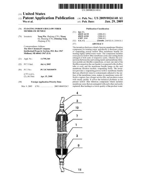
The invention discloses a kind of porous membrane filtration<br />
component for treating water, specifically it discloses a kind<br />
of suspending porous hollow fiber membrane bundle for<br />
treating highly turbid waste water. The component includes<br />
some porous hollow fiber membrane yarns and casting heads<br />
arranged at both ends of respective yams, wherein the connections<br />
between the said casting heads and membrane filtration<br />
module are flexible connections, at least one end of the<br />
flexible connection the cast header is connected with a hollow<br />
tube or cord, and the membrane bundle hangs on the said<br />
membrane filtration module, suspending freely. The invention<br />
provides a suspending porous hollow membrane bundle<br />
that can effectively remove contaminants adhered to the surface<br />
of the membrane yams, makes its membrane yams difficult<br />
to rupture, has a longer service life, and produces water<br />
with steady quality. It solves the technical problems in the<br />
present hollow fiber filtration component which includes<br />
membrane yams that are entangled with each other and easily<br />
ruptured, thus leading to a lower quality of the product water.<br />
4
Patent Application Publication Jan. 29, 2009 Sheet 1 of 5 US 2009/0026140 Al<br />
Figure 1 Figure 2
Patent Application Publication Jan. 29, 2009 Sheet 2 of S US 2009/0026140 Al<br />
Figure 3 Figure 4
Patent Application Publication Jan. 29, 2009 Sheet 3 of 5 US 2009/0026140 Al<br />
Figure 5<br />
7<br />
Figure 7 Figure 8
Patent Application Publication Jan. 29, 2009 Sheet 4 of 5 US 2009/0026140 Al<br />
Figure 9 Figure 10<br />
Figure 11 Figure 12
Patent Application Publication Jan. 29, 2009 Sheet 5 of 5 US 2009/0026140 Al<br />
19<br />
Figure 13
US 2009/0026140 Al Jan. 29, 2009<br />
1<br />
FLOATING POROUS HOLLOW FIBER<br />
MEMBRANE BUNDLE<br />
FIELD OF THE INVENTION<br />
[0001] This invention relates to a porous membrane filtration<br />
component for treating water, particularly a type of suspending<br />
porous hollow fiber membrane bundle for the treatment<br />
of highly turbid waste water.<br />
BACKGROUND OF THE INVENTION<br />
[0002] In recent years and with the development of membrane<br />
technology, membranes have more and more applications<br />
in waste water treatment. However, in the application<br />
process, particularly in the treatment applications of waste<br />
water with high turbidity, the membrane pollution problem<br />
has not been well resolved. With the improvement of membrane<br />
material properties and the reduction of membrane<br />
price, the control of membrane pollution has gradually<br />
become the main factor that limits its extensive application.<br />
[0003] In order to improve the evenness of water flow,<br />
permeation efficiency, and to resolve the pollution and blockage<br />
problems of the applied membrane, the importance of an<br />
optimized design for membrane modules has become more<br />
and more significant. Particularly during the application of<br />
direct filtration of highly turbid waste water with hollow fiber<br />
porous membrane, there emerges a module composed of hollow<br />
fiber porous membrane that can be directly immersed in<br />
a raw water tank or biochemical tank to perform filtration,<br />
generally both ends of the hollow fiber membrane bundles are<br />
respectively connected with water-collecting boards (tube)<br />
that are separated but standing face to face, kept loose without<br />
contact, and set in the water to be treated. The mentioned<br />
hollow fiber membranes can use known polyvinylidene fluoride,<br />
polyethylene, polyvinyl chloride, polypropylene, polyether<br />
sulfone or polysulfone materials, etc. Generally, there<br />
are independent aeration and cleaning components setup<br />
under the membrane module, so the membrane bundles are in<br />
a buffeting state to prevent begriming over the membrane<br />
surface and guarantee a high flow rate of the porous membrane<br />
in the filtering of highly turbid water. The layout form<br />
for the mentioned hollow fiber membrane bundles can be in a<br />
curtain shape, cuboid shape or cylinder shape.<br />
[0004] Immersion type membrane modules have been<br />
widely used. The published or approved patents include Chinese<br />
patent CN1331 124A, CN1509801A, CN1 121895C and<br />
US Patent U.S. Pat. No. 6,790,360. The abovementioned<br />
immersion type membrane modules have all resolved the<br />
anti-pollution and anti-blockage properties of the hollow<br />
porous membrane yarns to a certain degree, prolonging the<br />
lifespan and operating cycles of the modules to a certain<br />
degree as well. Both ends of the hollow fiber membrane yams<br />
for the abovementioned membrane modules generally were<br />
inserted into the sealed water-collecting tubes that are set face<br />
to face. Because the membrane yams inside the membrane<br />
modules were not restrained by a shell and although the<br />
buffeting freedom of the membrane yams was improved<br />
under the effect of aeration system, in order to prevent the<br />
entanglement among the membrane yams, the length of the<br />
membrane modules should not be very long. For example, in<br />
U.S. Pat. No. 6,790,360 the optimized length for membrane<br />
yarns is suggested to be 0.7 meter.<br />
[0005] Even so, immersion type porous membrane modules<br />
still have became a trend and direction for membrane<br />
module design in the sewage and waste water treatment field,<br />
and the membrane module structure and craft have been continuously<br />
improved. There is a curtain type immersion module<br />
including two vertically arranged upper and lower watercollecting<br />
tubes and hollow fiber membrane bundles in the<br />
middle. The feature is that the hollow fiber membrane bundle<br />
located between the upper and lower water-collecting tubes,<br />
could move right and left within a certain range, and the lower<br />
water-collecting tube could also shift up and down within a<br />
certain range, which provides the membrane bundle with a<br />
certain flexibility to improve anti-pollution capability of the<br />
membrane module. For another example, US Patent U52004/<br />
0188339A1 published an immersion module type membrane<br />
filtration device with an exchangeable membrane module<br />
with an aeration tube installed in the membrane bundles. Not<br />
only is the maintenance problem for the membrane module to<br />
a certain degree resolved and non-stop operation is realized,<br />
but also the aeration structure of the device and the antipollution<br />
property of the membrane yams are improved.<br />
[0006] In the above technologies, consideration was not<br />
given to the maintenance of the membrane module, the antipollution<br />
property of the membrane yams and the technical<br />
problem of water productivity for the complete membrane<br />
filtration device in all the designs of the membrane modules.<br />
[0007] The purpose of this invention is to provide a suspending<br />
hollow fiber porous membrane filtration module that<br />
can effectively prevent the entanglement of membrane yarns,<br />
effectively remove pollutants on the surface of membrane<br />
yarns, wherein the membrane yams do not rupture easily, the<br />
membrane modules have a long lifespan with stable water<br />
production quality.<br />
SUMMARY OF THE INVENTION<br />
[0008] This invention mainly provides for a suspending<br />
hollow fiber porous membrane filtration module with a reasonable<br />
structure that can effectively prevent entanglement of<br />
membrane yarns, effectively removes pollutants on the membrane<br />
yam surfaces which are difficult to rupture, provide a<br />
long application lifespan for the membrane module and provide<br />
steady water production quality. It can resolve the preexisting<br />
technical problem in the hollow fiber membrane<br />
filtration module e.g. the entangled membrane yams and easily<br />
rupture-able membrane yam which leads to the technical<br />
problem of low water production quality. This invention also<br />
provides convenient maintenance or exchanging of the membrane<br />
module for the whole membrane filtration equipment.<br />
[0009] The above technical problems in this invention are<br />
resolved through the technical scheme listed below: a suspending<br />
porous hollow fiber membrane bundle, comprising<br />
some porous hollow fiber membrane yarns and casting heads<br />
fixed on both ends of them and the casting heads of the said<br />
fixed membrane bundles are connected with two ends of the<br />
membrane filtration module in soft connection, with a hollow<br />
tube or cord on the casting head of at least one end of the soft<br />
connection, the casting head is connected with the said membrane<br />
filtration module in a suspending state. The said hollow<br />
fiber porous membrane bundle is completely immersed in the<br />
liquid to be filtered during the process, and the casting heads<br />
at both ends of the membrane bundle can move within a<br />
certain range, so in the process, not only can the membrane<br />
yarns suspend-swing and crash each other with water flow<br />
and airflow, but also the whole membrane bundle can move in<br />
a certain range, resulting in the improvement of the removal<br />
of the contaminants off the membrane yarn surface. Chiefly
US 2009/0026140 Al Jan. 29, 2009<br />
2<br />
because the casting heads at both ends of the membrane<br />
bundle can move within a certain range, when the membrane<br />
yarns move under the effect of water and air flows, the casting<br />
heads at both ends of the membrane bundle can move simultaneously<br />
also, then the oscillation angle between the membrane<br />
yam roots and the casting surface and the possibility of<br />
root rupture is significantly reduced, and dependability is<br />
improved. The said casting head at one end of the membrane<br />
bundle is connected with the water-collecting system of the<br />
said membrane filtration module through a hollow soft tube or<br />
cord, the casting head at the other end of the membrane<br />
bundle can be connected with the water-collecting system of<br />
the said membrane filtration module through a hollow soft<br />
tube, or directly connected with the other end of the module<br />
through a cord, then the soft connection between the said<br />
membrane bundle and the said membrane filtration module is<br />
accomplished. The cord includes the known flexible connection<br />
materials such as cords, springs, etc.<br />
iooioi of course, for the soft connection between the said<br />
membrane bundle and the membrane filtration module as<br />
well as the free suspending state for the membrane bundle in<br />
the water to be treated, any present known method can be<br />
adopted, for example, cord connection is adopted for both<br />
ends of the membrane bundle to make the membrane bundle<br />
suspend in the water to be treated, then the water outlet tube<br />
can connect to a certain location between the two casting<br />
heads for transportation of the produced water; or the membrane<br />
yams can be divided into two sections, and a fixture can<br />
be placed between the membrane yams to collect the produced<br />
water from both ends, and connection between the soft<br />
tube and the water production system is for the transportation<br />
of the produced water.<br />
[0011] Both ends of the said membrane yarns can be open,<br />
or only the water outlet end can be open.<br />
[0012] As an optimal choice, both ends of the said hollow<br />
fiber membrane yams are casted into cylinder shapes, and<br />
placed into the cup to form the casting heads with cavities.<br />
Both ends of the membrane yarns are open and placed inside<br />
the cavities, wherein the inner cavities of the both ends are<br />
connected with hollow soft tubes. The said cavities are watercollecting<br />
chambers. The hollow tubes at both ends are water<br />
outlet tubes. The soft connections on both ends are implemented<br />
by the water outlet tubes, the cavities on both ends of<br />
the casting heads. One end of the water outlet tube is connected<br />
with the cavity of the casting head, the other end is<br />
connected with the water production system of the module for<br />
transporting of the produced water.<br />
[0013] As an optimal choice, both ends of the said hollow<br />
fiber membrane yams are casted into cylinder shapes, and<br />
placed into the cup to form the casting heads with cavities.<br />
One end of the membrane yarn is open and placed inside the<br />
cavity for the connection to the hollow tube, and the cavity is<br />
a water-collecting chamber. The other end of the membrane<br />
yarn is sealed. The cavity of this end is connected with a cord<br />
or air distribution tube. One end of the membrane yarn is open<br />
and the other one is sealed. One end of the soft connection is<br />
water outlet tube for connection with the production system<br />
of the module for transportation of produced water. The other<br />
end of the soft connection can be a soft tube or cord. If a tube<br />
is used, it is connected with the air supply system of the<br />
module for air distribution and the cavity would become the<br />
air distribution chamber; if a cord is used, the soft connection<br />
between the casting head and the module is realized to make<br />
the ends of the membrane yarns move with the casting head to<br />
reduce stress around the root and the possibility of end rupture.<br />
[0014] As an optimal choice, a hollow tube is set in the said<br />
hollow fiber membrane yam. The hollow tube can be used as<br />
the transportation tube for the produced water connected with<br />
the water-collecting chamber in at least one end of the membrane<br />
bundle, whose ends are connected with the two ends of<br />
the casting heads respectively to transport the produced water<br />
inside the cavities of two casting heads. It can also be used as<br />
the air distribution tube connected to the air distribution<br />
chamber on one end of the membrane bundle there are several<br />
air distribution holes on the tube. Using a hollow tube as the<br />
air distribution tube can more effectively sweep the membrane<br />
yams, and an air distribution tube set-up can better<br />
sweep the roots of the membrane yarns to prevent the begriming<br />
on the roots from blockage of the membrane yams or even<br />
causing the rupture of the membrane yarns.<br />
[0015] As an optimal choice, the length of said hollow tube<br />
is larger than the distance between the two casting heads fixed<br />
on the membrane bundle but smaller than the length of the<br />
hollow fiber membrane yam. The damage on the membrane<br />
yarn caused by high oscillation amplitude of the membrane<br />
bundle can be prevented, so the membrane bundle is protected.<br />
[0016] As an optimal choice, the cord is set in the hollow<br />
fiber membrane yam with both ends of the cord connected<br />
with the casting heads fixed on both ends of the membrane<br />
yarn respectively, its length is larger than the distance<br />
between the casting heads on the membrane bundle but<br />
smaller than the length of the hollow fiber membrane yam.<br />
The damage on membrane yarns caused by the high oscillation<br />
amplitude of the membrane bundle can be prevented,<br />
which protects the membrane bundle.<br />
[0017] As an optimal choice, an air distribution tube is<br />
installed in the center of the casting head at the end of the said<br />
hollow fiber membrane yarn. There are air distribution holes<br />
over it, with one end of the air distribution tube as free end<br />
extending to the middle of the membrane yam and the other<br />
end connecting to the air distribution system.<br />
[0018] As an optimal choice, at least one end of casting<br />
head on two ends of the said membrane bundle is connected<br />
with the water-collecting system or air distribution system of<br />
the said membrane filtration module through a hollow soft<br />
tube.<br />
[0019] The said suspending hollow fiber porous membrane<br />
bundle can not only be used in an immersion type superfiltration<br />
device, but it can also be used in a membrane biological<br />
reaction device. The said suspending hollow fiber<br />
porous membrane bundle can be connected with the corresponding<br />
hangers of the membrane module through flexible<br />
hanging cords or connected with the water-collecting system<br />
or air supply system of the module through water outlet tube<br />
or air inlet tube. Several said suspending hollow fiber porous<br />
membrane filtration modules can be fixed to the corresponding<br />
hanger brackets through the module hangers. The waterproducing<br />
soft tube for the module is connected parallel to the<br />
water collecting tube and the air inlet soft tube is connected<br />
parallel to the compressed air tube, then a filtration system is<br />
formed to adjust to the filtration system in different water<br />
generation scales.<br />
[0020] This invention has the features of a simple structure,<br />
reasonable layout, compact device, convenient production,<br />
small area requirement, low energy consumption, simple
US 2009/0026140 Al Jan. 29, 2009<br />
3<br />
operation, good water quality, high treatment efficiency and<br />
longer operational cycle, etc. It can be used alone or in connection<br />
with other water treatment processes of highly turbid<br />
water. It is particularly appropriate in membrane biological<br />
reaction devices.<br />
DESCRIPTION OF THE DRAWINGS<br />
[0021] FIG. 1 is the profile view of a suspending hollow<br />
fiber porous membrane bundle (there are water outlet tubes in<br />
the membrane bundle) in this invention.<br />
[0022] FIG. 2 is the profile view of a suspending hollow<br />
fiber porous membrane bundle (there are air distribution tubes<br />
in the membrane bundle) in this invention.<br />
[0023] FIG. 3 is the profile view of a suspending hollow<br />
fiber porous membrane bundle (there are cords in the membrane<br />
bundle) in this invention.<br />
[0024] FIG. 4 is the profile view of a suspending hollow<br />
fiber porous membrane bundle (there are short air distribution<br />
tubes in the membrane bundle) in this invention.<br />
[0025] FIG. S is the schematic diagram of the casting head<br />
below a suspending hollow fiber porous membrane bundle<br />
shown in FIG. 1 in this invention.<br />
[0026] FIG. 6 is the schematic diagram of the casting head<br />
above a suspending hollow fiber porous membrane bundle<br />
shown in FIG. 1 in this invention.<br />
[0027] FIG. 7 is the schematic diagram of the lower casting<br />
head in a suspending hollow fiber porous membrane bundle<br />
shown in FIG. 2 in this invention.<br />
[0028] FIG. 8 is the schematic diagram of the upper casting<br />
head in a suspending hollow fiber porous membrane bundle<br />
shown in FIG. 2 in this invention.<br />
[0029] FIG. 9 is the schematic diagram of the lower casting<br />
head in a suspending hollow fiber porous membrane bundle<br />
shown in FIG. 3 in this invention.<br />
[0030] FIG. 10 is the schematic diagram of the upper casting<br />
head in a suspending hollow fiber porous membrane<br />
bundle shown in FIG. 3 in this invention.<br />
[0031] FIG. 11 is the schematic diagram of the lower casting<br />
head in a suspending hollow fiber porous membrane<br />
bundle shown in FIG. 4 in this invention.<br />
[0032] FIG. 12 is the schematic diagram of the upper casting<br />
head in a suspending hollow fiber porous membrane<br />
bundle shown in FIG. 4 in this invention.<br />
[0033] FIG. 13 is the schematic diagram of the membrane<br />
filtration module composed of several suspending hollow<br />
fiber membrane bundles in this invention.<br />
DESCRIPTION OF THE PREFERRED<br />
EMBODIMENTS<br />
[0034] Through the examples and the attached diagrams,<br />
the detailed description for the technical scheme in this invention<br />
is made as follows.<br />
Example 1<br />
[0035] As shown in FIG. 1, a suspending hollow fiber<br />
porous membrane bundle, comprises several hollow fiber<br />
membrane yarns 1, casting heads 2 fixed on the ends of the<br />
yarns, water outlet end and hollow tube 5. The membrane<br />
bundle that is completely immersed in the raw water to be<br />
filtered is composed of 300 hollow fiber porous membrane<br />
yarns 1 with 0.01 im average pore size of the hollow fiber<br />
porous membrane yam in cylinder shape of 50 mm diameter.<br />
Polyurethane is used to cast both ends of the membrane<br />
bundle inside the cylinder casting head 2 with both ends open<br />
(as shown in FIGS. Sand 6). Both ends of the said hollow fiber<br />
membrane yarn 1 are casted into cylinder shape and placed<br />
into cast header 2 with cavities 3 (that is the water-collecting<br />
chamber), the water-collecting chamber is connected with<br />
water outlet tube 4 through the water outlet end and water<br />
outlet tube 4 is connected with the water-collecting system of<br />
the filtration system. The net length of the membrane yam 1<br />
between casting heads 2 at both ends of the membrane bundle<br />
is 1500 mm The water-collecting chambers on each end of<br />
the membrane bundle are connected through a hollow tube 5.<br />
The produced water collected by the water-collecting chamber<br />
on one end of the membrane bundle is transported to the<br />
other end through hollow tube 5. The produced water from<br />
both ends is combined together and flows to the water-collecting<br />
system of the filtration system through water outlet<br />
end and water outlet tube 4. As a result, the said hollow tube<br />
S is not only the water outlet tube, but can also prevent the<br />
damage on the membrane yam caused by high oscillation<br />
amplitude of the membrane bundle and protect the membrane<br />
bundle. Because soft connections are used for both ends of the<br />
membrane bundle, wherein at least one end of the soft connection<br />
uses the soft tube and the hollow fiber porous membrane<br />
bundle is completely immersed into the liquid to be<br />
filtered. The fixtures on both ends of the membrane bundle<br />
can move within a certain range, therefore besides the membrane<br />
yams that can be suspended, move and contact each<br />
other along with water flow and air flow, the complete membrane<br />
bundle can move within a range as well.<br />
Example 2<br />
[0036] As shown in FIG. 2, a suspending hollow fiber<br />
porous membrane bundle, comprises several hollow fiber<br />
membrane yams 1, casting heads 2 fixed on the ends of the<br />
membrane yams, water outlet end 9 and air supply end 10.<br />
The membrane bundle, which is completely immersed inside<br />
the raw water to be filtered, is composed of 400 hollow fibers<br />
porous membrane yams 1 with average pore size of 0.1 tim,<br />
with the diameter of the cylinder shape membrane bundle of<br />
60 mm Polyurethane is used to cast one end of the membrane<br />
bundle into the cylinder casting head 2 with the end open.<br />
Both ends of the said hollow fiber membrane yarn 1 are casted<br />
into cylinder shape and placed into casting head 2 with cavities<br />
3 (that is the water-collecting chamber). The water-collecting<br />
chamber is connected to water outlet tube 4 through<br />
the water outlet end. Polyurethane is used to cast the other end<br />
of the membrane bundle into the cylinder casting head 2 with<br />
the end sealed. The casting heads are placed in the cup to form<br />
cavity 3 (that is the air distribution chamber), the air distribution<br />
chamber is connected to air supply tube through air<br />
supply end (as shown in FIGS. 7 and 8). Water outlet tube 4,<br />
air supply tube 11 are connected with the water collecting<br />
system and compressed air supply system of the filtration<br />
system respectively. The net length of the membrane yarn 1<br />
between casting heads 2 at both ends of the membrane bundle<br />
is 1500 mm There is a hollow tube S set in the membrane<br />
bundle with one end connected to the air distribution chamber<br />
on one end of the membrane bundle and the other end binding<br />
with the corresponding membrane bundle cast header with<br />
the end sealed. There are air distribution holes 7 evenly distributed<br />
on the hollow tube 5, which can provide aeration on<br />
membrane yams 1 during work. Therefore, the hollow tube S<br />
is not only the air distribution tube, but also can prevent the<br />
damage on membrane yarn 1 caused by high oscillation
US 2009/0026140 Al Jan. 29, 2009<br />
4<br />
amplitude of the membrane bundle and protect the membrane<br />
bundle. Because soft tube connections are used in both ends<br />
of the membrane bundle and the hollow fiber porous membrane<br />
bundle is completely immersed into the liquid to be<br />
filtered, the casting heads at both ends of the membrane<br />
bundle can move within a certain range. So besides the membrane<br />
yarns can float, move and contact each other along with<br />
water flow and air flow, the complete membrane bundle can<br />
move within a range as well.<br />
Example 3<br />
[0037] As shown in FIG. 3, a suspending hollow fiber<br />
porous membrane bundle, comprises several hollow fiber<br />
membrane yarns 1, casting heads 2 fixed on the ends of the<br />
yarns, water outlet end and middle cord 6. The membrane<br />
bundle that is completely immersed in the raw water to be<br />
filtered is composed of 200 hollow fibers porous membrane<br />
yarns with average pore size of 0.2 tim, with the diameter of<br />
the cylinder shape membrane bundle of 60 mm Polyurethane<br />
is used for both ends of the membrane bundle to cast in the<br />
cylinder cast header 2 with the ends open (as shown in FIGS.<br />
9 and 10). Both ends of the said hollow fiber membrane yarn<br />
1 are casted into cylinder shape and placed into cast header 2<br />
with cavities 3 (that is the water-collecting chamber). The<br />
water-collecting chamber is connected to water outlet tube 4<br />
through the water outlet end; the water outlet tube 4 is connected<br />
to the water-collecting system of the filtration system.<br />
The net length of the membrane yam 1 between casting heads<br />
2 at both ends of the membrane bundle is 1500 mm Watercollecting<br />
chambers on both ends of the membrane bundle are<br />
connected through a hollow tube. In order to prevent the<br />
damage on membrane yam caused by high oscillation amplitude<br />
of the membrane bundle, cord 6 is set up in the middle of<br />
the membrane yarn 1 and between the two casting heads on<br />
both ends to protect the membrane bundle. Because soft connections<br />
are used for both ends of the membrane bundle and<br />
the hollow fiber porous membrane bundle is completely<br />
immersed into the liquid to be filtered, the casting heads 2 on<br />
both ends of the membrane bundle can move within a certain<br />
range, therefore, besides the membrane yams that can float,<br />
move and contact each other along with water flow and air<br />
flow, the complete membrane bundle can move within a<br />
range.<br />
Example 4<br />
[0038] As shown in FIG. 4, a suspending hollow fiber<br />
porous membrane bundle, comprises several hollow fiber<br />
membrane yarns 1, casting heads 2 fixed on the ends of the<br />
yarns, water outlet end and air supply end. Membrane bundle<br />
that is completely immersed inside the raw water to be filtered<br />
is composed of 200 hollow fiber porous membrane yarns 1<br />
with an average pore size of 0.01 lun and with a diameter of<br />
the cylinder shape membrane bundle of 160 mm As shown in<br />
FIGS. 11 and 12, polyurethane is used to cast one end of the<br />
membrane bundle into the cylinder shape cast header with the<br />
end open. Both ends of the said hollow fiber membrane yarn<br />
1 are casted into cylinder shape and placed into cast header 2<br />
with cavities 3 (that is water-collecting chamber). The watercollecting<br />
chamber is connected with the water outlet tube 4<br />
through the water outlet end. As shown in FIG. 4, polyurethane<br />
is used to cast the other end of the membrane bundle<br />
into the cylinder cast header 2 with the end sealed. The center<br />
of the cast header has an air supply tube 8 extending to the<br />
center of membrane yarn 1, and there are air distribution holes<br />
over the tube. There is a cavity 3 (that is the air distribution<br />
chamber) in the cast header; the air distribution chamber is<br />
connected to air supply tube 11 through air supply end. Water<br />
outlet tube 4 and air supply tube 11 are connected with the<br />
water-collecting system and compressed air supply system of<br />
the filtration system respectively.<br />
[0039] The net length of the membrane yam 1 between<br />
casting heads 2 at both ends of the membrane bundle is 1000<br />
mm Because soft tube connections are adopted in both ends<br />
of the membrane bundle and the hollow fiber porous membrane<br />
bundle is completely immersed into the liquid to be<br />
filtered, the casting heads at both ends of the membrane<br />
bundle can move within a certain range, therefore, besides the<br />
membrane yams that can float, move and contact each other<br />
along with water flow and air flow, the complete membrane<br />
bundle can move within a range.<br />
Example 5<br />
[0040] As shown in FIG. 9, a membrane filtration module<br />
composed of several suspending hollow fiber porous membrane<br />
bundles in Example 1, comprising module head 13,<br />
casting heads 2 fixed on the ends of the membrane yams,<br />
aeration head 12, central tube 15, water outlet tube 4, etc. and<br />
8 hollow fiber porous membrane bundles 17 that surround the<br />
central tube 15 evenly and is completely immersed in the raw<br />
water to be filtered. Module head 13 and aeration head 12 are<br />
connected together through the central tube 15 with diameter<br />
of 40 mm The size of the module head 13 is smaller than that<br />
of the aeration head 12 to make the whole module appear to be<br />
in tower shape, which helps the direction of air flow. The<br />
module head 13 is round, its diameter is 150 mm the aeration<br />
head 12 is a double cone with 200 mm diameter and there are<br />
several air distributing holes in radial distribution. The conical<br />
angle is 120° for the upper conical surface of the aeration<br />
head 12. The conical angle for the lower conical surface is<br />
130°. The side of aeration head 12 that is against the module<br />
head 13 has air pressure adjusting tube 16 that faces the<br />
central tube 15; the air pressure adjusting tube 16 can adjust<br />
the air pressure inside the aeration head 12 to increase the<br />
aeration result.<br />
[0041] There is a hang ring 14 on module head 13 connected<br />
to the module bracket of the filtration system through<br />
soft cord by soft connection.<br />
[0042] There are a water outlet tube 19 and an air distribution<br />
tube 20 on the module head 13, water outlet tube 19 is<br />
connected to water-collecting extension tube and outlet<br />
pump; air distribution tube 20 is connected to compressed air<br />
inlet extension tube and is connected with the aeration head<br />
12 through central tube 15. The water to be purified goes<br />
through the pores on the walls of hollow fiber porous membrane<br />
to enter the inside of the hollow fiber porous membrane<br />
and flows into water-collecting tube and it is extracted by the<br />
pump. The two ends of the central tube 15 close to the module<br />
head 13 and the aeration head 12 have air exit leading board<br />
18, which has the leading effect on the air flow coming from<br />
the aeration head 12, enhances the sweeping result for the<br />
ends of the hollow fiber porous membrane bundle to remove<br />
the pollutants.<br />
[0043] Obviously, the abovementioned devices, processes<br />
and methods can be changed or modified by the technicians in<br />
this field withinthis invention. The above statement should be<br />
considered as an embodiment of the invention, instead of a<br />
kind of limit.
US 2009/0026140 Al Jan. 29, 2009<br />
5<br />
[0044] This invention is appropriate for the purification<br />
treatments of surface water, underground water, municipal<br />
waste water, industrial waste water, etc. with high turbidity.<br />
1-10. (canceled)<br />
11.A membrane filtration module comprising a plurality of<br />
membrane bundles flexibly connected between a module<br />
head and an aeration head;<br />
wherein a membrane bundle comprises: a plurality of hollow<br />
fiber porous membrane yarns extending between a<br />
first end and second end, a first casting head fixed on said<br />
first end of said yarns, and a second casting head fixed on<br />
said second end of said yams; and<br />
wherein said first casting head is connected to said module<br />
head by a flexible water outlet tube.<br />
12. The module of claim 11 wherein said second casting<br />
head is connected to said aeration head by a flexible cord.<br />
13. The module of claim 12 wherein said first and second<br />
casting heads each include a water collection chamber, and<br />
said membrane bundle comprises a hollow tube connecting<br />
said water collection chambers.<br />
14. The module of claim 11 wherein said second casting<br />
head is connected to said aeration head by a first air supply<br />
tube.<br />
15. The module of claim 14 wherein said second casting<br />
head comprises an air distribution chamber and a second air<br />
supply tube connected to said air distribution chamber for<br />
distributing air within said membrane bundle.<br />
16. The module of claim 15 wherein said second air supply<br />
tube comprises a first end connected to said air distribution<br />
chamber and a second end sealed and fixed to said first casting<br />
head.<br />
17. The module of claim 11 comprising a central tube<br />
connected to said module head and aeration head.<br />
18. The module of claim 17 wherein said module head<br />
comprises a water outlet tube and an air distribution tube, and<br />
wherein said air distribution tube is connected to said aeration<br />
head through said central tube.<br />
19. A filtration system comprising: a water-collection<br />
extension tube, a compressed air inlet extension tube, and a<br />
plurality of membrane filtration modules wherein a module<br />
comprises:<br />
a plurality of membrane bundles flexibly connected<br />
between a module head and an aeration head,<br />
a central tube connected between said module head and<br />
said aeration head,<br />
said module head comprising a water outlet tube connected<br />
to said water-collection extension tube, and an air distribution<br />
tube connected to said compressed air inlet<br />
extension tube, and wherein said air distribution tube is<br />
connected to said aeration head through said central<br />
tube,<br />
wherein a membrane bundle comprises: a plurality of hollow<br />
fiber porous membrane yams extending between a<br />
first end and second end, a first casting head fixed on said<br />
first end of said yams, and a second casting bead fixed on<br />
said second end of said yams; and<br />
wherein said first casting head is connected to said module<br />
head by a flexible water outlet tube.<br />
20. The filtration system of claim 19 wherein said second<br />
casting head of said membrane bundle is connected to said<br />
aeration head by a flexible cord.<br />
21. The filtration system of claim 20 wherein said first and<br />
second casting heads each include a water collection chamber,<br />
and said membrane bundle comprises a hollow tube<br />
connecting said water collection chambers.<br />
22. The filtration system of claim 19 wherein said second<br />
casting head of said membrane bundle is connected to said<br />
aeration head by a first air supply tube.<br />
23. The filtration system of claim 22 wherein said second<br />
casting head comprises an air distribution chamber and a<br />
second air supply tube connected to said air distribution<br />
chamber for distributing air within said membrane bundle.<br />
24. The filtration system of claim 23 wherein said second<br />
air supply tube comprises a first end connected to said air<br />
distribution chamber of said second casting head and a second<br />
end sealed and fixed to said first casting head.<br />
25. A method of treating water using a filtration system of<br />
claim 19 wherein water is filtered by passing through hollow<br />
fiber porous membrane yams and is transported from the<br />
yarns to a water-collection extension tube.