Gulph Creek Stone Arch Bridge - Delaware Department of ...
Gulph Creek Stone Arch Bridge - Delaware Department of ...
Gulph Creek Stone Arch Bridge - Delaware Department of ...

You also want an ePaper? Increase the reach of your titles
YUMPU automatically turns print PDFs into web optimized ePapers that Google loves.
Chapter 3—Historic Context for Common Historic <strong>Bridge</strong> Types<br />
7. <strong>Gulph</strong> <strong>Creek</strong> <strong>Stone</strong> <strong>Arch</strong> <strong>Bridge</strong> (1789), spanning <strong>Gulph</strong> <strong>Creek</strong> at Old<br />
<strong>Gulph</strong> Road, Upper Merion, Montgomery County, PA. HAER PA-309.<br />
8. Possum Kingdom <strong>Stone</strong> <strong>Arch</strong> <strong>Bridge</strong> (1940-42), spanning Brazos River at<br />
State Route 16, Graford, Palo Pinto County, TX HAER TX-62.<br />
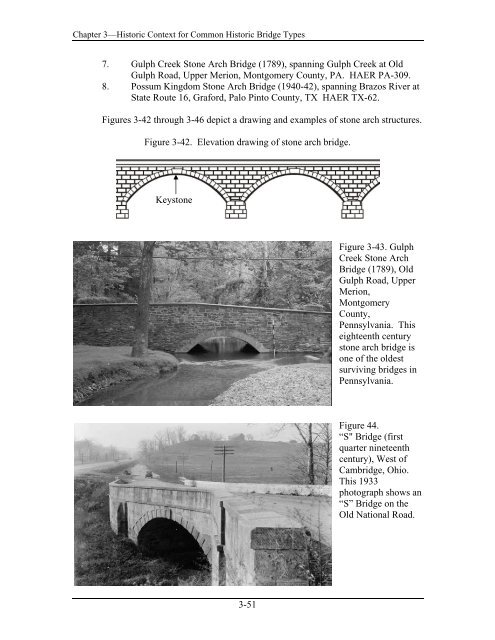
Figures 3-42 through 3-46 depict a drawing and examples <strong>of</strong> stone arch structures.<br />
Figure 3-42. Elevation drawing <strong>of</strong> stone arch bridge.<br />
Keystone<br />
Figure 3-43. <strong>Gulph</strong><br />
<strong>Creek</strong> <strong>Stone</strong> <strong>Arch</strong><br />
<strong>Bridge</strong> (1789), Old<br />
<strong>Gulph</strong> Road, Upper<br />
Merion,<br />
Montgomery<br />
County,<br />
Pennsylvania. This<br />
eighteenth century<br />
stone arch bridge is<br />
one <strong>of</strong> the oldest<br />
surviving bridges in<br />
Pennsylvania.<br />
Figure 44.<br />
“S" <strong>Bridge</strong> (first<br />
quarter nineteenth<br />
century), West <strong>of</strong><br />
Cambridge, Ohio.<br />
This 1933<br />
photograph shows an<br />
“S” <strong>Bridge</strong> on the<br />
Old National Road.<br />
3-51
Chapter 3—Historic Context for Common Historic <strong>Bridge</strong> Types<br />
Figure 3-45.<br />
Cabin John Aqueduct <strong>Bridge</strong> (1864), MacArthur Boulevard, spanning<br />
Cabin John <strong>Creek</strong> at Cabin John, Maryland. With a single arch span <strong>of</strong><br />
220 feet, this bridge was the longest masonry arch bridge in the world<br />
until 1905.<br />
Figure 3-46.<br />
Possum Kingdom <strong>Stone</strong> <strong>Arch</strong> <strong>Bridge</strong> (1940-42), spanning Brazos River at<br />
State Route 16, Graford, Texas. This structure is an example <strong>of</strong> a Works<br />
Progress Administration-built stone arch bridge.<br />
3-52
Chapter 3—Historic Context for Common Historic <strong>Bridge</strong> Types<br />
3.2.2 Reinforced Concrete Melan/von Emperger/Thacher <strong>Arch</strong><br />
History and Description: The first concrete arch bridge in the United States was<br />
a plain, un-reinforced concrete footbridge with a 31-foot span, constructed in Prospect<br />
Park, Brooklyn, New York, in 1871. This little bridge, however, was not to have many<br />
successors. Despite the advantages <strong>of</strong> plasticity and good compressive strength, unreinforced<br />
concrete has little tensile strength, and thus its usefulness for bridge<br />
construction was limited. The path to full exploitation <strong>of</strong> concrete as a building material<br />
lay in the development <strong>of</strong> a system <strong>of</strong> reinforcement that made use <strong>of</strong> the tensile<br />
properties <strong>of</strong> metal.<br />
The oldest reinforced concrete bridge in the United States is the National Historic<br />
Civil Engineering Landmark Alvord Lake <strong>Bridge</strong> (1889) in San Francisco’s Golden Gate<br />
Park (HAER CA-33). It was one <strong>of</strong> two bridges built in San Francisco that were designed<br />
by Ernest L. Ransome (1844-1917), the “father” <strong>of</strong> reinforced concrete construction in<br />
the United States. Reinforced with rods or bars, which were twisted in accordance with<br />
the design Ransome patented in 1884, this modest structure was the predecessor <strong>of</strong><br />
thousands <strong>of</strong> reinforced concrete bridges built across the nation in the twentieth century.<br />
After serving as an apprentice in the family concrete factory in England, Ransome<br />
immigrated to the United States in the late 1860s to exploit his father’s patent for<br />
“concrete stone.” In the early 1870s, while working as superintendent <strong>of</strong> the Pacific <strong>Stone</strong><br />
Company <strong>of</strong> San Francisco, he established a factory to make concrete blocks. According<br />
to Waddell (9, p. 28), Ransome introduced reinforced concrete to America in 1874, but it<br />
was not until 1884 that he received the patent (# 305,226) that became the basis <strong>of</strong> the<br />
Ransome System for reinforcing concrete. Ransome also adapted a concrete mixer to<br />
twist iron bars up to two inches in diameter, believing that twisted bars had greater tensile<br />
strength than smooth round bars. His primary focus was on finding the best way to make<br />
the concrete adhere to the metal.<br />
Hoping to capitalize on his invention in non-bridge applications, he moved to<br />
New York City and opened the Ransome Concrete Company at 11 Broadway Avenue. At<br />
this point, Ransome had clearly left bridge design behind him in favor <strong>of</strong> building system<br />
development. The Ransome system proved to be very popular for building construction,<br />
and several notable buildings were erected using it, including the Artic Oil Works in San<br />
Francisco, California (1884), an early American reinforced concrete building; the Leland<br />
Stanford Junior Museum in Palo Alto, California (1894), the largest reinforced concrete<br />
public building in the world at the time; and the Ingalls Building in Cincinnati, Ohio<br />
(1903), the first reinforced concrete skyscraper.<br />
In 1902, Henry C. Turner, a former Ransome assistant, founded the Turner<br />
Construction Company and began fully exploiting the Ransome System. Apparently<br />
Turner had acquired some rights to the Ransome patent. Ransome continued to work on<br />
his own, however, and the Foster-Armstrong piano factory in Rochester, New York, was<br />
built in 1905 according to the “Ransome-Smith reinforced concrete method.” The<br />
“Smith” in the name referred to borax king Francis M. Smith, who, along with Ransome,<br />
3-53
Chapter 3—Historic Context for Common Historic <strong>Bridge</strong> Types<br />
formed the Ransome & Smith Contracting Company and built an addition to the Pacific<br />
Coast Borax Company factory in Alameda, California, in 1889, and a warehouse for the<br />
Pacific Coast Borax Company facility in Bayonne, New Jersey, in 1898, using<br />
Ransome’s method. Ransome also designed an elegant little arched footbridge over a<br />
pond at Presdeleau, Smith’s estate at Shelter Island, New York. This structure, which still<br />
exists, and the two bridges erected in San Francisco, are the only bridges known to have<br />
been designed by Ransome. Other engineers and builders eventually propagated his<br />
design for use in buildings, but in the late 1890s and well into the twentieth century there<br />
were other reinforcing systems for concrete bridges that were better promoted by their<br />
designers and much more widely used in bridge construction.<br />
In 1893, a Viennese engineer named Joseph Melan (1853-1941) patented in<br />
America a concrete reinforcing system using parallel metal I-beams curved to the form <strong>of</strong><br />
the arch and embedded in the concrete (#505,054). This was a fairly conservative system<br />
because the bridges in which it was employed were basically steel arches encased in<br />
concrete rather than concrete arches with metal reinforcement. That conservatism<br />
appealed, however, to bridge engineers who preferred the Melan system over a rival<br />
methodology <strong>of</strong> reinforcement that had become popular in Europe, developed by Joseph<br />
Monier and his son, Jean. The Monier system, patented in France in 1873 and in the<br />
United States in 1883, used a mesh <strong>of</strong> small rods to add tensile strength to concrete. It<br />
was virtually impossible to calculate strains in the structure using this system, but tests<br />
proved that the system would work, with limitations. With faith in the superiority <strong>of</strong> his<br />
own design, Melan opened the Melan <strong>Arch</strong> Construction Company in New York City<br />
soon after acquiring his patent. It would be left to others, however, to fully exploit the<br />
Melan method <strong>of</strong> concrete reinforcement.<br />
In April 1894, an Austrian engineer named Fritz von Emperger (1862-1942)<br />
presented a paper on the Melan system at a meeting <strong>of</strong> the American Society <strong>of</strong> Civil<br />
Engineers. The Society later published his paper as “The Development and Recent<br />
Improvement <strong>of</strong> Concrete-Iron Highway <strong>Bridge</strong>s” in volume 31 <strong>of</strong> Transactions. Soon<br />
after von Emperger’s presentation, a contractor from Minneapolis, Minnesota, named W.<br />
S. Hewitt contacted the Austrian and asked him to design a bridge according to the Melan<br />
system in Rock Rapids, Lyon County, Iowa. The plans were complete by June 1894, and<br />
the closed-spandrel arch bridge, with a span <strong>of</strong> about 30 feet, was finished soon<br />
thereafter. The Rock Rapids <strong>Bridge</strong> (now called simply the Melan <strong>Bridge</strong>) became the<br />
first bridge to be built using the Melan design methodology (16). Although relocated and<br />
no longer in use as a vehicular bridge, this structure still exists. Less than a year later, von<br />
Emperger designed and built a slightly larger bridge in Eden Park, Cincinnati, Ohio, with<br />
a span <strong>of</strong> approximately 70 feet. This bridge remains in very good condition, and is still<br />
in service (17).<br />
In 1897, von Emperger patented a system <strong>of</strong> reinforcing concrete arches with steel<br />
ribs consisting <strong>of</strong> a pair <strong>of</strong> parallel, curved, rolled I-beams, each beam placed near one<br />
surface <strong>of</strong> the concrete, with secondary members connecting the beams (#583,464). Both<br />
bars extended into the abutments <strong>of</strong> the arch. This system was enough <strong>of</strong> a refinement <strong>of</strong><br />
the one developed by Melan to win a patent, but it still followed the ideas espoused by<br />
3-54
Chapter 3—Historic Context for Common Historic <strong>Bridge</strong> Types<br />
the Austrian engineer. With confidence in the future <strong>of</strong> the Melan system, von Emperger<br />
had earlier founded the Melan <strong>Arch</strong> Construction Company in New York City, and went<br />
on to build several Melan-style bridges. One small Melan-system bridge that may have<br />
been built by von Emperger’s company was the Doan Brook <strong>Bridge</strong> over Jephta Road in<br />
Cleveland (1900). By the turn <strong>of</strong> the century, however, von Emperger had left his<br />
company in the care <strong>of</strong> his design engineer, William Meuser, who formed a new<br />
partnership about 1900 with a western agent for the von Emperger firm, Edwin Thacher<br />
(1840-1920), who had built the first large Melan arch bridge in 1896 over the Kansas<br />
River in Topeka, Kansas. In 1901, Meuser and Thacher renamed their firm the Concrete<br />
Steel Engineering Company, and under this name built more than 200 Melan arch bridges<br />
across the country by 1912, with Thacher acting as the chief engineer and dominant<br />
partner.<br />
Prior to his association with Meuser, Thacher had a varied career that was similar<br />
in many respects with other bridge engineers <strong>of</strong> his time. He received a degree in civil<br />
engineering from Rensselaer Polytechnic Institute in 1863, and like so many <strong>of</strong> his peers,<br />
began the acquisition <strong>of</strong> practical experience by working for a number <strong>of</strong> railroads, before<br />
relocating to Pittsburgh to serve as Design Engineer with one <strong>of</strong> the most important<br />
bridge companies <strong>of</strong> the nineteenth century, the Keystone <strong>Bridge</strong> Company. In 1899,<br />
Thacher was granted a patent (#617,615) for an arch construction similar to that <strong>of</strong> von<br />
Emperger in that ribs in pairs, one near the intrados and one near the extrados, are placed<br />
one above the other, and one, if not both ribs extend into the abutment. The difference<br />
with the von Emperger patent is that in the Thacher system the ribs are independent <strong>of</strong><br />
one another.<br />
Reinforcement <strong>of</strong> concrete with I-beams used far more steel than reinforcement<br />
systems using bars or rods, which could be more economically and selectively located in<br />
areas <strong>of</strong> high tensile stress. There were many patents issued in the early decades <strong>of</strong> the<br />
twentieth century covering variations in shape, deformation, and methods <strong>of</strong> bending or<br />
shaping the bars. Although not all <strong>of</strong> these methodologies relied upon some version <strong>of</strong><br />
the twisted bar system patented by Ransome, his emphasis on metal bars as a<br />
strengthening element for concrete bridges, rather than metal beams, eventually began to<br />
predominate over the Melan/von Emperger/Thacher line <strong>of</strong> development. Although<br />
Melan-style bridges may be found in the East, Midwest and in California, they are<br />
relatively rare in the South, Southwest, and in the mountain states.<br />
Significance Assessment: This group represents the first generation <strong>of</strong> patented<br />
reinforced concrete arch bridges constructed in America. They were built in the late<br />
1890s through the first decade <strong>of</strong> the twentieth century, prior to the establishment <strong>of</strong> state<br />
highway departments. All documented Melan, von Emperger and Thacher bridges in<br />
reasonably good condition and retaining their character-defining features are highly<br />
significant within the context <strong>of</strong> this study. Character-defining features include the arch<br />
ring, barrel, spandrel wall, railing or parapet, abutments and wingwalls.<br />
Along with these patented examples are a group <strong>of</strong> small, experimental,<br />
reinforced concrete arch bridges built by county engineers and engineers working locally.<br />
3-55
Chapter 3—Historic Context for Common Historic <strong>Bridge</strong> Types<br />
Survey work has begun to turn up these early experimental examples though there has<br />
been little in-depth research. These early examples have not been widely included in<br />
many statewide bridge surveys, since the bridges are locally- or municipally-owned. Yet<br />
they illustrate the variety and interest that the new material <strong>of</strong> the twentieth century,<br />
concrete, incited in engineers. Most <strong>of</strong> these structures would be short to intermediate<br />
spans located on rural country roads or lightly trafficked municipal roads. Because some<br />
<strong>of</strong> these bridges might be the earliest examples <strong>of</strong> reinforced concrete bridge construction<br />
in the United States, further study is required to determine their significance.<br />
Examples <strong>of</strong> Reinforced Concrete Melan/von Emperger/Thacher <strong>Arch</strong><br />
1. Melan <strong>Bridge</strong> (also known as Rock Rapids <strong>Bridge</strong>) (1893), Emma Slater<br />
Park (Moved from Dry Run <strong>Creek</strong>), Rock Rapids vicinity Lyon County,<br />
IA. NRHP listed 1974. HAER IA-15.<br />
2. White <strong>Bridge</strong> (1897); Hyde Park, Duchess County, New York, part <strong>of</strong><br />
Roosevelt-Vanderbuilt Historic Site. HAER NY-138.<br />
3. Frankford Avenue <strong>Bridge</strong> (1904); Philadelphia County, Pennsylvania.<br />
NRHP listed 1988. HAER PA-471.<br />
4. Sandy Hill <strong>Bridge</strong>, <strong>Bridge</strong> Street (1906-07), spanning Hudson River,<br />
Hudson Falls, Washington County, NY. HAER NY-185.<br />
5. Alvord Lake <strong>Bridge</strong> (1889), San Francisco, San Francisco County, CA.<br />
HAER CA-33.<br />
Figures 3-47 though 3-49 depict, respectively, the first reinforced concrete bridge<br />
in the United States, and two structures built using the Melan system.<br />
Figure 3-47.<br />
Alvord Lake <strong>Bridge</strong> (1889), San Francisco, San Francisco County,<br />
California. Designed by Ernest Ransome, this is the first reinforced<br />
concrete bridge in the United States.<br />
3-56
Chapter 3—Historic Context for Common Historic <strong>Bridge</strong> Types<br />
Figure 3-48.<br />
Melan <strong>Arch</strong> <strong>Bridge</strong> (1893), Emma Slater Park (Moved from Dry Run<br />
<strong>Creek</strong>), Rock Rapids vicinity, Lyon County, Iowa. The photograph<br />
illustrates an example <strong>of</strong> a von Emperger bridge.<br />
Figure 3-49.<br />
Sandy Hill <strong>Bridge</strong>, <strong>Bridge</strong> Street (1906-07), spanning Hudson River,<br />
Hudson Falls, New York. This structure was built using the Melan<br />
system.<br />
3-57
Chapter 3—Historic Context for Common Historic <strong>Bridge</strong> Types<br />
3.2.3 Reinforced Concrete Luten <strong>Arch</strong><br />
History and Description: As James L. Cooper (18, p.37) has stated, “Daniel B.<br />
Luten did more than any other single person to advance the movement from concretesteel<br />
to reinforced concrete bridge design….” What Cooper means by this is that Luten<br />
diverged from the relatively conservative Melan/von Emperger/Thacher line <strong>of</strong><br />
development that placed the importance <strong>of</strong> steel (or iron) as a load-bearing element in<br />
bridge arches above that <strong>of</strong> concrete, and aggressively promoted a system that stemmed<br />
more from the Monier methodology that gave primacy to concrete in load bearing, with<br />
metal as a strengthening element. And he did so with great success. As Cooper also<br />
notes, “Luten’s considerable influence reached towards the continent’s corners from<br />
Maine to California and from Canada to Mexico. Probably a thousand out <strong>of</strong><br />
approximately twelve thousand <strong>of</strong> his structures remain to bear witness to his once<br />
ubiquitous presence.”<br />
Luten (1869-1946) received a Bachelor <strong>of</strong> Science degree in civil engineering<br />
from the University <strong>of</strong> Michigan in 1894, and taught civil engineering and surveying<br />
there for a year after graduation. From 1896 to 1900, he taught at Purdue University as<br />
an instructor <strong>of</strong> architectural and sanitary engineering. Finding the life <strong>of</strong> an academic<br />
too confining, he left the university in 1900, secured the first <strong>of</strong> many patents for<br />
reinforced concrete bridges, and published a catalog for the “Timber-Tie Concrete <strong>Arch</strong><br />
Company” (19, p. 4). He only secured one contract in response to his catalog, but the<br />
following year he formed the National <strong>Bridge</strong> Company. With an entrepreneurial flair<br />
that surpassed his considerable skills as an engineer, he began to market and construct<br />
reinforced concrete bridges across the Midwest. He also began submitting articles to the<br />
Engineering News-Record and the Railroad Gazette about this time, and continued to be<br />
a major contributor to these and other pr<strong>of</strong>essional publications for more than twenty<br />
years.<br />
Although Luten built all three types <strong>of</strong> reinforced concrete arches, including open<br />
spandrel deck arches and open spandrel through arches, an article entitled “The Proper<br />
Curvature for a Filled Spandrel <strong>Arch</strong>,” published in the September 12, 1902, edition <strong>of</strong><br />
Railroad Gazette illustrates the bridge form that became the focus <strong>of</strong> Luten’s design<br />
practice, the filled spandrel “timber” tied deck arch (20, p. 11).<br />
Luten was prolific in his acquisition <strong>of</strong> patents, and he acquired nearly fifty by the<br />
early 1920s. He was granted so many patents that, according to him, it was virtually<br />
impossible for anyone else to build a reinforced concrete arch without infringing on one<br />
<strong>of</strong> his designs. To a large extent, Luten’s strategy for success, and that <strong>of</strong> other<br />
entrepreneurial designers, relied on exploitation <strong>of</strong> the patent system in the United States.<br />
As bridge historian James Hippen (21, p. 6) has stated, “the trick became to include in a<br />
patent claim as many as one could <strong>of</strong> the possible arrangements <strong>of</strong> reinforcing and other<br />
elements in a concrete bridge, and then collect royalties or sue for infringement” (21).<br />
Eventually the royalty costs paid by private and public bridge builders and the cost <strong>of</strong><br />
battling Luten in court became so great that an organized resistance to his way <strong>of</strong> doing<br />
business arose. The tide <strong>of</strong> opposition from the engineering pr<strong>of</strong>ession and the legal<br />
3-58
Chapter 3—Historic Context for Common Historic <strong>Bridge</strong> Types<br />
establishment finally washed over Luten in 1918, and his patents, along with some <strong>of</strong><br />
Thacher’s, were invalidated.<br />
Despite his defeats, by 1919 Luten claimed to have designed at least 17,000<br />
bridges in all but three states. Although the actual number may be lower, it is certain that<br />
he did more than any other designer or builder to encourage the construction <strong>of</strong><br />
reinforced concrete arches by county and municipal governments, and hundreds <strong>of</strong> Luten<br />
designed bridges still exist across the country, although the largest groupings may be<br />
found in California, the states <strong>of</strong> the Midwest, and in the states along the Atlantic<br />
seaboard. The popularity <strong>of</strong> his design did not continue far beyond the first two decades<br />
<strong>of</strong> the twentieth century, however, due both to the patent issues and because his designs<br />
were simply not efficient in the use <strong>of</strong> steel and concrete. Other engineers eventually<br />
surpassed Luten in the area he thought most his own; the practical combination <strong>of</strong> theory<br />
and empirical practice.<br />
Significance Assessment: Thousands <strong>of</strong> Luten arches likely survive nationwide<br />
out <strong>of</strong> the 17,000 claimed to have been built during the 1910s and 1920s. They are<br />
characterized as having either open or closed spandrels, single and multiple rib or barrel<br />
arches <strong>of</strong> short to intermediate span (40 to 150 feet). However, since this describes most<br />
arch forms, documentation is needed to established whether a bridge is a Luten patented<br />
or designed example. Documentation includes bridge plaques, city and county records<br />
and comparison to known Luten bridges in state bridge surveys.<br />
Documented Luten arches with a high level <strong>of</strong> integrity, although quite common,<br />
are significant within the context <strong>of</strong> this study if they retain their character-defining<br />
features. Character-defining features include the arch ring, spandrels, ribs or barrel,<br />
railing or parapet, and abutments and wingwalls. Luten was an important promoter and<br />
builder <strong>of</strong> the reinforced concrete arch form in the early-20th century.<br />
Examples <strong>of</strong> Reinforced Concrete Luten <strong>Arch</strong><br />
1. Illinois River <strong>Bridge</strong> (1922), Benton County, AR. NRHP listed 1988 in<br />
Benton County MRA.<br />
2. Harp <strong>Creek</strong> <strong>Bridge</strong> (1928), Newton County, AR. NRHP listed 1990 in<br />
Historic <strong>Bridge</strong>s <strong>of</strong> Arkansas MPS.<br />
3. Andrew J. Sullivan <strong>Bridge</strong> (1928), Whitley County, KY. Determined<br />
NRHP eligible by SHPO.<br />
4. American Legion Memorial <strong>Bridge</strong> (1930), Grand Traverse County, MI.<br />
NRHP listed 2000 in Highway <strong>Bridge</strong>s <strong>of</strong> Michigan MPS.<br />
5. Andrew J. Sullivan <strong>Bridge</strong> (1928), spanning Cumberland River,<br />
Williamsburg vicinity, Whitley County, KY. HAER KY-51.<br />
6. Milwaukee Street <strong>Bridge</strong> (1930), spanning Rock River, Watertown,<br />
Jefferson County, WI. HAER WI-33.<br />
Figures 3-50 and 3-51 depict examples <strong>of</strong> Luten closed and open spandrel<br />
designs.<br />
3-59
Chapter 3—Historic Context for Common Historic <strong>Bridge</strong> Types<br />
Figure 3-50.<br />
Andrew J. Sullivan <strong>Bridge</strong> (1928), spanning Cumberland River,<br />
Williamsburg vicinity, Whitley County, Kentucky. This structure is an<br />
example <strong>of</strong> a Luten closed spandrel arch.<br />
Figure 3-51.<br />
Milwaukee Street <strong>Bridge</strong> (1930), spanning Rock River, Watertown,<br />
Wisconsin. The photographs below show an example <strong>of</strong> the Luten openspandrel<br />
arch.<br />
3-51a. Three-quarter view.<br />
3-51b. Detail <strong>of</strong> open spandrel.<br />
3-60
Chapter 3—Historic Context for Common Historic <strong>Bridge</strong> Types<br />
3.2.4 Reinforced Concrete Marsh and Rainbow (Through) <strong>Arch</strong><br />
History and Description: Another type <strong>of</strong> reinforced concrete arch bridge that<br />
was built in considerable numbers throughout the United States is the through arch,<br />
which was developed in the 1910s. In this type, the crown <strong>of</strong> the arch is above the deck<br />
and the foundations <strong>of</strong> the arch are below the deck, and hangers suspend the deck from<br />
the arch. The best known patented design <strong>of</strong> this type was developed by James Barney<br />
Marsh (1856-1936), an engineer from Des Moines, Iowa. After graduating with a<br />
Bachelor <strong>of</strong> Mechanical Engineering in 1882 from the Iowa State College <strong>of</strong> Agriculture<br />
and Mechanical Arts (now Iowa State University) in Ames, Iowa, Marsh moved to<br />
nearby Des Moines to become a contracting agent for the King <strong>Bridge</strong> Company <strong>of</strong><br />
Cleveland, Ohio. Through the end <strong>of</strong> the century, Marsh sold and supervised the erection<br />
<strong>of</strong> iron, and then steel truss bridges in Iowa, Montana, South Dakota, Minnesota,<br />
Colorado, and five other western states (21, p. 5).<br />
By 1896, Marsh had decided to turn the skills he had learned working for others<br />
to his own advantage, and he founded the Marsh <strong>Bridge</strong> Company. Marsh built both<br />
steel and reinforced concrete bridges for city and county governments, including a Melan<br />
arch at Waterloo, Iowa, in 1903, and an eight-span Melan arch for Second Avenue in<br />
Cedar Rapids, Iowa, in 1906. In 1909, the company was put in the hands <strong>of</strong> a receiver,<br />
and Marsh reorganized his business as the Marsh Engineering Company. Late that year<br />
he completed a non-Melan style, three-span arch bridge in Dunkerton, Iowa, which still<br />
stands. The royalties that Marsh had to pay to American holders <strong>of</strong> the Melan patent<br />
were becoming increasingly onerous, and soon after being sued by Daniel Luten in 1911<br />
over a bridge built by Marsh’s company in Minnesota, Marsh began experimenting with<br />
his own designs for reinforced concrete bridges. In 1912 he received patent number<br />
1,035,026, which covered the basic design for which he would be best known, the Marsh<br />
arch. The deck <strong>of</strong> a Marsh arch is supported by vertical ties between the crown <strong>of</strong> the<br />
arch and the floor beams, and all forces in tension are exerted on the vertical members.<br />
Most Marsh arches were small highway bridges with span lengths from 40 to 100 feet.<br />
Although most bridge historians have tended to assert that the Marsh arch was, like many<br />
other reinforced concrete arch designs <strong>of</strong> the time, somewhat wasteful <strong>of</strong> materials,<br />
Hippen (21, p. 6) has argued that the design is “more sophisticated, both structurally and<br />
economically, than has been thought in the past.”<br />
Commonly called a “rainbow” arch, the Marsh design was not constructed in<br />
large numbers outside the Midwest, but scattered examples still survive in other regions.<br />
One <strong>of</strong> his earliest bridges, built the same year that he filed his first patent application<br />
(1911), is the bridge over the Little Cottonwood River in Blue Earth County, Minnesota.<br />
Oklahoma still has an example across Squirrel <strong>Creek</strong> in Pottawatomie County (1917);<br />
one <strong>of</strong> two built in that state. Possibly the largest Marsh arch is a five-span bridge built at<br />
Cotter, Arkansas, in 1930. Each span <strong>of</strong> this National Historic Civil Engineering<br />
Landmark is 190 feet in length. It is similar in many respects to the only remaining<br />
multi-span Marsh <strong>Arch</strong> <strong>Bridge</strong> in Iowa, the Lake City <strong>Bridge</strong> (1914), which has three<br />
spans <strong>of</strong> 80 feet each. Another multi-span Marsh <strong>Arch</strong> <strong>Bridge</strong> listed in the NRHP is<br />
located at Fort Morgan, Colorado. Other multi-span Marsh <strong>Arch</strong> <strong>Bridge</strong>s, now<br />
3-61
Chapter 3—Historic Context for Common Historic <strong>Bridge</strong> Types<br />
demolished, have been documented across the Little Wabash River at Carmi, Illinois<br />
(1917); and across the Cannonball River at Mott, North Dakota (1921). The greatest<br />
number <strong>of</strong> extant Marsh <strong>Arch</strong> <strong>Bridge</strong>s, however, may be found in Kansas, Iowa and<br />
Ohio.<br />
The Marsh arch design covered by his 1912 patent is not a tied arch because the<br />
floor system did not serve as a tie between the ends <strong>of</strong> the arch ribs. According to<br />
Hippen (21, p. 7), the Marsh patented design allowed the floor to slide independently <strong>of</strong><br />
the arches so that longitudinal expansion and contraction would be transmitted between<br />
the floor system and the arches only through the hangers, which were flexible enough to<br />
bend slightly. This was achieved through use <strong>of</strong> a slip joint between the deck and the<br />
arch where they intersect (20, p. 27). Marsh secured another patent in 1921 (#1,388,584)<br />
for a supposedly flexible short hanger to be used as a modification <strong>of</strong> the 1912 design,<br />
and this modification assumes a continuance <strong>of</strong> the sliding deck concept. Marsh was<br />
known to have produced both a fixed arch design and a tied arch design, and his company<br />
built both types. Apparently, he did not have a patent for the fixed arch design (21, p. 9).<br />
Many tied arch spans are called “rainbow” arches, but a clear distinction should<br />
be made between those spans based on the 1912 Marsh patent and true tied-arch designs.<br />
Occasionally, confusion has arisen in the literature <strong>of</strong> bridge history due to the tendency<br />
to characterize both Marsh patented designs and non-Marsh designs as “rainbow arches.”<br />
As an example, in Historic Highway <strong>Bridge</strong>s in Pennsylvania, the Second Street <strong>Bridge</strong><br />
in <strong>Delaware</strong> County is referred to as a “bowstring arch,” and it is stated that concrete<br />
bowstring arch bridges are sometimes known as “Rainbow” and “Marsh” arches.<br />
However, a bowstring span, whether expressed as a metal truss or a reinforced concrete<br />
arch, is by definition a tied-arch design, whereas the Marsh arch, as covered by the 1912<br />
patent, is not. Care should be taken in identification and evaluation <strong>of</strong> reinforced<br />
concrete through “rainbow” arches to differentiate between fixed and tied arch designs.<br />
Significance Assessment: The Marsh arch is another example <strong>of</strong> the early<br />
proprietary patented reinforced concrete arch form built during the first few decades <strong>of</strong><br />
the 20th century (1910-1920). A technological characteristic <strong>of</strong> the Marsh arch was its<br />
ability to be fabricated without the use <strong>of</strong> falsework. All concrete arches need a<br />
temporary wooden scaffolding to support the formwork until the concrete is cured and<br />
structurally stable. March arches essentially are a steel armature around which concrete is<br />
formed – a steel framework incased in concrete. Hence, the formwork for the concrete<br />
could be hung from the reinforcing armature without the need for scaffolding in the bed<br />
<strong>of</strong> the river.<br />
March arches are an aesthetic and pleasing form contributing to the cultural<br />
landscape, especially in the Midwest. <strong>Bridge</strong>s documented to have been built by Marsh<br />
or under his patent are significant within the context <strong>of</strong> this study if they retain their<br />
character-defining features, which include the arch (from below to above the deck) end<br />
posts, suspenders (vertical ties), lower chord, floor beams, railing and piers or abutments.<br />
Documentation might be found in the form <strong>of</strong> a bridge plaque or local government<br />
3-62
Chapter 3—Historic Context for Common Historic <strong>Bridge</strong> Types<br />
records. Kansas has completed a study <strong>of</strong> its Marsh arches, which can be found at<br />
http://midwestbridges.com/marsharch.html.<br />
In addition to the documented Marsh arches found in the mid-western states, there<br />
are other rainbow type arches built in other parts <strong>of</strong> the country. Examples that visually<br />
resemble Marsh arches but cannot be documented, possess less significance within the<br />
context <strong>of</strong> this study than the documented Marsh arch, but are still considered significant<br />
if they retain their character-defining features.<br />
Examples Reinforced Concrete Marsh or Rainbow (Through) <strong>Arch</strong><br />
1. Marsh Concrete Rainbow <strong>Arch</strong> <strong>Bridge</strong> (1911), Blue Earth County, MN.<br />
NRHP listed 1980 in Blue Earth County MRA.<br />
2. Lake City <strong>Bridge</strong> (1914), Calhoun County, IA. NRHP listed 1989.<br />
3. Marsh Rainbow <strong>Arch</strong> <strong>Bridge</strong> (Spring Street <strong>Bridge</strong>) (1916), Chippewa<br />
County, WI. NRHP listed 1982.<br />
4. Cotter <strong>Bridge</strong> (1930), Baxter County, AR. NRHP listed 1990 in Historic<br />
<strong>Bridge</strong>s <strong>of</strong> Arkansas MPS.<br />
5. Blacksmith <strong>Creek</strong> <strong>Bridge</strong> (1930), Topeka, Shawnee County, KS. NRHP<br />
listed 1983 in Rainbow Marsh <strong>Arch</strong> <strong>Bridge</strong>s <strong>of</strong> Kansas Thematic Resource<br />
Nomination.<br />
6. Mott Rainbow <strong>Arch</strong> <strong>Bridge</strong> (1921), spanning Cannonball River, Mott,<br />
Hettinger County, ND. HAER ND-1.<br />
7. Spring Street <strong>Bridge</strong> (1916), spanning Duncan <strong>Creek</strong>, Chippewa Falls,<br />
Chippewa County, WI. HAER WI-37.<br />
Figures 3-52 and 3-53 are examples <strong>of</strong> the patented Marsh arch.<br />
3-63
Chapter 3—Historic Context for Common Historic <strong>Bridge</strong> Types<br />
Figure 3-52.<br />
Spring Street <strong>Bridge</strong> (1916), spanning Duncan <strong>Creek</strong>, Chippewa Falls,<br />
Wisconsin. This structure is the state’s only example <strong>of</strong> a patented<br />
Marsh arch.<br />
Figure 3-53.<br />
Mott Rainbow <strong>Arch</strong> <strong>Bridge</strong> (1921), spanning Cannonball River, Mott,<br />
North Dakota. This two-span bridge is an example <strong>of</strong> the patented Marsh<br />
arch.<br />
3-64
Chapter 3—Historic Context for Common Historic <strong>Bridge</strong> Types<br />
3.2.5 Reinforced Concrete Closed Spandrel <strong>Arch</strong><br />
History and Description: Closed spandrel arch bridges are the most basic <strong>of</strong><br />
reinforced concrete bridge types in that they mimic the appearance <strong>of</strong> masonry arch<br />
bridges.<br />
Closed spandrel means that the area between the travel surface (deck) and the<br />
arch ring was filled in, thus replicating the massive appearance <strong>of</strong> the masonry arch<br />
bridge. The spandrel wall actually serves as a retaining wall in a closed spandrel arch<br />
bridge, holding in the fill material, which could be earth, rubble, or some combination <strong>of</strong><br />
materials. Live (traffic) loads are borne by the fill material and, to a lesser extent, by the<br />
spandrel walls. The arch may be constructed either as a single structural element (an arch<br />
barrel) or in separate parallel longitudinal ribs, which are usually braced with cross ties.<br />
Although the rib design requires more formwork to construct, it also requires less<br />
material. The barrel arch design, which has some structural and visual similarities to<br />
stone arch bridges, is more likely to be found on older and smaller bridges while the rib<br />
design is more likely to be found on larger bridges. The barrel arch bridge is also<br />
sometimes faced with brick or stone, making it appear similar to a masonry arch bridge.<br />
This type <strong>of</strong> bridge is suitable for short span lengths, and may be found in all<br />
regions <strong>of</strong> the country, however, representation tends to be greatest in states that were<br />
settled early and have a tradition <strong>of</strong> stone arch construction. A rare variation is the closed<br />
spandrel arch with no fill material. This type <strong>of</strong> arch has a floor system similar to that <strong>of</strong><br />
an open spandrel arch bridge (23, p. 7.5.2). The concrete arch was <strong>of</strong>ten not among the<br />
standardized bridge types developed by the state departments <strong>of</strong> transportation in their<br />
early years.<br />
Significance Assessment: Closed spandrel concrete arches predate open<br />
spandrels, as the closed spandrel type harkens back to the stone arches that the earliest<br />
forms imitated. This type was not built for long as engineers soon realized that<br />
significant material could be saved and a consequent reduction <strong>of</strong> weight could be<br />
achieved by eliminating the triangular section between the deck and arch. Hence, open<br />
spandrels were born (despite the additional costs <strong>of</strong> constructing formwork for the<br />
spandrel columns).<br />
Filled spandrel concrete arches date primarily from the earliest decades <strong>of</strong><br />
reinforced concrete, i.e., the 1890s through the 1920s. They are not as common (then and<br />
now) as many <strong>of</strong> the standardized bridge types built during this same era, such as<br />
concrete slabs and girders. Because they are not as common, they are significant within<br />
the context <strong>of</strong> this study, as they represent the evolution <strong>of</strong> concrete technology. Filled<br />
spandrel arches that are built under standardized transportation department plans would<br />
also be considered significant.<br />
To be considered significant, filled spandrel arches should have integrity, through<br />
the retention <strong>of</strong> their character-defining features, which include the arch ring, barrel,<br />
spandrel wall, railing or parapet, end posts, piers and/or abutments and wingwalls.<br />
3-65
Chapter 3—Historic Context for Common Historic <strong>Bridge</strong> Types<br />
Examples <strong>of</strong> Reinforced Concrete Closed Spandrel <strong>Arch</strong><br />
1. Alvord Lake <strong>Bridge</strong> (1889), Golden Gate Park, City <strong>of</strong> San Francisco, San<br />
Francisco County, CA. HAER CA-33.<br />
2. Queene Avenue <strong>Bridge</strong> (1905), Hennepin County, MN. NRHP listed<br />
1989 in Reinforced Concrete Highway <strong>Bridge</strong>s in Minnesota MPS.<br />
3. Fromberg <strong>Bridge</strong> (1914), Carbon County, MT. NRHP listed 1993 in<br />
Fromberg MPS. HAER MT-7.<br />
4. Market Street <strong>Bridge</strong> (1928), Dauphin County, PA. NRHP listed 1988 in<br />
Highway <strong>Bridge</strong>s Owned by the Commonwealth <strong>of</strong> Pennsylvania,<br />
<strong>Department</strong> <strong>of</strong> Transportation Thematic Resource Nomination. HAER<br />
PA-342<br />
5. Penns <strong>Creek</strong> <strong>Bridge</strong> (1919), State Route 1014 at Penns <strong>Creek</strong>, Selinsgrove<br />
vicinity, Snyder County, PA. HAER PA-284.<br />
6. Curry <strong>Creek</strong> <strong>Bridge</strong> (1926), spanning Curry <strong>Creek</strong> at State Route 15,<br />
Jefferson, Jackson County, GA. HAER GA-67.<br />
Figures 3-54 and 3-55 illustrate the filled spandrel arch type.<br />
Figure 3-54. Elevation drawing <strong>of</strong> filled spandrel concrete arch.<br />
Closed<br />
spandrel area<br />
Figure 3-55. Penns<br />
<strong>Creek</strong> <strong>Bridge</strong> (1919),<br />
State Route 1014 at<br />
Penns <strong>Creek</strong>,<br />
Selinsgrove vicinity,<br />
Snyder County,<br />
Pennsylvania. This<br />
bridge is an example <strong>of</strong><br />
a reinforced closed<br />
spandrel concrete<br />
structure.<br />
3-66
Chapter 3—Historic Context for Common Historic <strong>Bridge</strong> Types<br />
3.2.6 Reinforced Concrete Open Spandrel <strong>Arch</strong><br />
History and Description: This type <strong>of</strong> bridge was first constructed in the United<br />
States about 1906, and was the dominant form for concrete bridges in the 1920s and<br />
1930s (22, p. 20). Open spandrel concrete bridges evolved, as the span length <strong>of</strong><br />
reinforced concrete arches increased and the weight and cost <strong>of</strong> the material <strong>of</strong> spandrel<br />
walls <strong>of</strong> the closed spandrel type bridge became prohibitive. By eliminating these walls<br />
and the fill material inside them, not only could dead loads be reduced, but cost savings<br />
were seen in materials. In addition to economics and durability, aesthetics was another<br />
factor. Open spandrel bridges had a lightness and visual appeal not possible with heavier<br />
closed spandrel bridges. This relative openness made open spandrel arch bridges more<br />
aesthetically appealing for prominent or scenic locations. Open spandrel construction<br />
marked engineering prowess during the height <strong>of</strong> long span concrete arch bridges during<br />
the 1930s and 1940s. By the 1940s, the open spandrel concrete structure began to be<br />
supplanted by the more economic pre-stressed beam and reinforced concrete girder<br />
structures.<br />
Open spandrel arch bridges have pierced spandrel walls with no fill material, and<br />
the spandrel columns transmit dead and live loads from the travel surface (deck) to the<br />
arch. The arch ring may be either a solid barrel, as in the closed spandrel arch, or ribbed.<br />
Although open spandrel arch bridges require more formwork to construct than filled<br />
spandrel bridges, they also <strong>of</strong>fer some economy <strong>of</strong> materials, particularly for long span<br />
lengths.<br />
An example <strong>of</strong> this type <strong>of</strong> structure is Campbell’s <strong>Bridge</strong>, spanning Unami <strong>Creek</strong><br />
at Allentown Road in Bucks County, Pennsylvania, which was completed in 1907, and is<br />
the oldest <strong>of</strong> its type in the PennDOT system. It is certainly among the oldest <strong>of</strong> its type<br />
in the nation.<br />
Significance Assessment: Open spandrel concrete arches, while not uncommon,<br />
are not as common (then and now) as many <strong>of</strong> the standardized bridge types built during<br />
this same era. Because they are not as common, they are significant within the context <strong>of</strong><br />
this study as they represent the evolution <strong>of</strong> concrete technology. To be considered<br />
significant, open spandrel arches should have integrity through the retention <strong>of</strong> their<br />
character-defining features, which include arch ribs, ring or barrel; spandrel; spandrel<br />
columns; railing or parapet; and piers, abutments and wingwalls.<br />
Examples <strong>of</strong> Reinforced Concrete Open Spandrel <strong>Arch</strong><br />
1. Tenth Street <strong>Bridge</strong> (1920), Cascade County, MT. NRHP listed 1996.<br />
HAER MT-8.<br />
2. Gervais Street <strong>Bridge</strong> (1927), Richland County, SC. NRHP listed 1980.<br />
HAER SC-16.<br />
3. Cedar Avenue <strong>Bridge</strong> (1929), Hennepin County, MN. NRHP listed 1989<br />
in Reinforced Concrete Highway <strong>Bridge</strong>s in Minnesota MPS.<br />
3-67
Chapter 3—Historic Context for Common Historic <strong>Bridge</strong> Types<br />
4. George Westinghouse <strong>Bridge</strong> (1932), Allegheny County, PA. NRHP<br />
listed 1977. HAER PA-446.<br />
5. Broad River Highway <strong>Bridge</strong> (1935), State Route 72, spanning Broad<br />
River, Carlton vicinity, Madison County, GA. HAER GA-47.<br />
Figures 3-56 and 3-57 depict the open spandrel concrete arch type.<br />
Figure 3-56. Elevation drawing <strong>of</strong> open spandrel concrete arch.<br />
Figure 3-57.<br />
Broad River Highway <strong>Bridge</strong> (1935), State Route 72, spanning Broad<br />
River, Carlton vicinity, Madison County, Georgia. This bridge is an<br />
example <strong>of</strong> the open spandrel concrete arch.<br />
open<br />
spandrel<br />
area<br />
3-68
Chapter 3—Historic Context for Common Historic <strong>Bridge</strong> Types<br />
3.2.7 Steel Tied <strong>Arch</strong><br />
History and Description: Steel arches can be fixed, hinged, or tied. Tied steel<br />
arches, also commonly referred to as “tied thru (or through) arches,” are descendents <strong>of</strong><br />
the iron “bowstring” trusses (discussed in Section 3.1.6) that were patented in the midnineteenth<br />
century.<br />
Structurally, the advantage <strong>of</strong> the steel tied arch is that they do not require large<br />
abutments to counter the thrust <strong>of</strong> the arch action. Abutments could be smaller and more<br />
economic. A tied arch span has a structural element, usually a floor system, which ties<br />
the ends <strong>of</strong> the arch together. According to the FHWA <strong>Bridge</strong> Inspector’s Training<br />
Manual, a tied arch is a variation <strong>of</strong> a through arch in which the horizontal thrust <strong>of</strong> the<br />
arch reactions is transferred to the horizontal tie, which acts in tension. The bowstring<br />
arch is essentially a tied arch expressed in metal, but not all metal tied arches should<br />
necessarily be characterized as bowstrings. The arch members are called ribs and can be<br />
fabricated as beams, girders or trusses, and can be further classified as solid rib, braced<br />
rib, or spandrel braced. The arch members can be riveted, bolted or welded together<br />
(23, p. 8.8.3).<br />
Lengths vary from 30 to 50 feet for the short spans. The shorter spans were<br />
predominately constructed in the 1930s. An early steel tied-arch bridge is the Franklin<br />
Street <strong>Bridge</strong> (1939) spanning Oil <strong>Creek</strong> in Crawford County, Pennsylvania. In its<br />
modern form, tied arches have been designed for spans ranging from 180 feet to over 900<br />
feet. The longest steel tied-arch bridge in the United States is the 912-foot long<br />
Moundsville <strong>Bridge</strong> (1986) over the Ohio River in Marshall County, West Virginia.<br />
Significance Assessment: The tied steel arches built before 1955 (the end <strong>of</strong> the<br />
historic period covered in this study), many dating to the second quarter <strong>of</strong> the twentieth<br />
century, are notable bridge structures because <strong>of</strong> their distinctive arch form. They were<br />
not built in great numbers, thus examples that retain their character-defining features will<br />
possess significance within the context <strong>of</strong> this study. Character-defining features include<br />
the curved top girder or truss (ribs), suspenders, ties, the bottom chord and floor system.<br />
Examples <strong>of</strong> Steel Tied <strong>Arch</strong><br />
1. West End—North Side <strong>Bridge</strong> (1932), Allegheny County, PA. NRHP<br />
listed 1979.<br />
2. Franklin Street <strong>Bridge</strong> (1939), spanning Oil <strong>Creek</strong> at Franklin Street,<br />
Titusville, Crawford County, PA. HAER PA-494.<br />
3. Braceville <strong>Bridge</strong> (1939), spanning Southern Pacific Railroad tracks at<br />
State Route 129, Braceville vicinity, Grundy County, IL, HAER IL-141.<br />
4. I-95 <strong>Bridge</strong> over Myrtle Avenue (1955), Jacksonville, FL. Considered<br />
NRHP eligible in Historic Highway <strong>Bridge</strong>s <strong>of</strong> Florida (2004).<br />
5. Blue River <strong>Bridge</strong> (1933), Jackson County, MO. Listed as NRHP eligible<br />
in Missouri Historic <strong>Bridge</strong> Inventory (1996).<br />
6. John McLoughlin <strong>Bridge</strong> (1933), Oregon 99E, spanning Clackamas River,<br />
Oregon. NRHP eligible 1985. HAER OR-67.<br />
3-69
Chapter 3—Historic Context for Common Historic <strong>Bridge</strong> Types<br />
Figure 3-58 depicts an example <strong>of</strong> a steel tied arch.<br />
Figure 3-58. Franklin Street <strong>Bridge</strong> (1939), spanning Oil <strong>Creek</strong> at Franklin Street,<br />
Titusville, Pennsylvania. Designed by a county engineer, this bridge is a<br />
steel tied arch.<br />
3-58a. Three quarter view.<br />
3-58b. Detail <strong>of</strong> connection.<br />
3-70
Chapter 3—Historic Context for Common Historic <strong>Bridge</strong> Types<br />
3.2.8 Reinforced Concrete Tied <strong>Arch</strong><br />
History and Description: Reinforced concrete arch spans can be fixed, hinged<br />
or tied. Like tied steel arches, reinforced concrete tied arches (or through arches) are a<br />
phenomena <strong>of</strong> the twentieth century and were built to avoid heavy massive abutments,<br />
thus saving money. They were constructed during the “heroic” period <strong>of</strong> reinforced<br />
concrete arch construction, which began in the 1920s and extended till the end <strong>of</strong> the<br />
1930s.<br />
Unlike traditional fixed through arches, the ends <strong>of</strong> the ribs <strong>of</strong> the concrete tied<br />
arch are not integral parts <strong>of</strong> the piers resulting in the containment <strong>of</strong> the horizontal thrust<br />
action by the pier mass. Instead, the arch rib ends are connected to the deck by hinged<br />
shoes and rebar. The advantage <strong>of</strong> the tied arch design is that the entire structure acts as a<br />
beam and places the entire vertical load on the supporting abutments or piers, thus<br />
negating the need for large abutments to resist the thrust <strong>of</strong> the arch. Lighter, less<br />
expensive abutments could then be used. Lengths ranged from short spans <strong>of</strong> 30 to 40<br />
feet to moderately long spans in excess <strong>of</strong> 200 feet.<br />
Tied concrete arches are architecturally distinctive due to their prominent arch<br />
form. Larger spans exhibit monumental qualities, like some <strong>of</strong> Oregon state bridge<br />
engineer Conde McCullough’s coastal spans. One early example <strong>of</strong> a reinforced concrete<br />
tied-arch through bridge is the Benson Street <strong>Bridge</strong> (1910) over the gate fork <strong>of</strong> Mill<br />
<strong>Creek</strong>, about eight miles north <strong>of</strong> the Cincinnati central business district in Hamilton<br />
County, Ohio. Designed by Deputy County Surveyor E. A. Gast, this bridge may be the<br />
oldest, and first, tied arch, reinforced concrete bridge in the United States. The deck is<br />
suspended from two arch ribs by nine hangers, with the steel rods hooked around rib<br />
reinforcement above and floor rods below. The arch ribs are entirely above the travel<br />
surface. This design was chosen because studies had shown that the surviving masonry<br />
abutments from an earlier truss bridge at the site could support the load <strong>of</strong> a new bridge,<br />
if the weight <strong>of</strong> the bridge could be distributed evenly over the width <strong>of</strong> the abutments.<br />
A more modest example is State <strong>Bridge</strong> NC-246 (1942) in New Castle County,<br />
<strong>Delaware</strong>, which is that state’s first and only remaining example <strong>of</strong> this type. Like so<br />
many <strong>of</strong> the earlier tied-arch bridges that preceded it around the country, this structure<br />
replaced a metal truss bridge. Although the specific reasons for selection <strong>of</strong> a tied-arch<br />
design at this site are unknown, the type was generally employed where subsurface<br />
conditions made massive abutments or piers impractical.<br />
Significance Assessment: The concrete tied arches built before 1955 (the end <strong>of</strong><br />
the historic period covered in this study), many dating to the second quarter <strong>of</strong> the<br />
twentieth century, are notable bridge structures because <strong>of</strong> their distinctive arch form.<br />
They were not built in great numbers, thus examples that retain their character-defining<br />
features will possess significance within the context <strong>of</strong> this study. Character-defining<br />
features include the curved top chord (rib), bottom chord, suspenders/ties/hangers, hinged<br />
shoes, floor beams, and wingwalls, abutments or piers. Railings may also be characterdefining<br />
features <strong>of</strong> some bridges.<br />
3-71
Chapter 3—Historic Context for Common Historic <strong>Bridge</strong> Types<br />
Examples <strong>of</strong> Reinforced Concrete Tied <strong>Arch</strong><br />
1. Benson Street <strong>Bridge</strong> (1910), Hamilton County, OH. HAER OH-50.<br />
2. Quarry Road <strong>Bridge</strong> (1916), spanning Conestoga <strong>Creek</strong>, Lancaster<br />
County, PA. Determined NRHP eligible in 1993 as part <strong>of</strong> state-wide<br />
historic bridge survey.<br />
3. Rumsey <strong>Bridge</strong> (1930), County Road 41 over Cache <strong>Creek</strong>, Yolo County,<br />
CA. Determined NRHP eligible in 1986 as part <strong>of</strong> state-wide historic<br />
bridge survey.<br />
4. Wilson River <strong>Bridge</strong> (1931), US 101 over Wilson River, Oregon. NRHP<br />
listed 1985. HAER OR-39.<br />
Figure 3-59 depicts a reinforced concrete tied arch structure.<br />
Figure 3-59.<br />
Wilson River <strong>Bridge</strong> (1930-31), spans Wilson River at United States<br />
Highway 101, Tillamook, Tillamook County, Oregon. This bridge was<br />
designed by Oregon state bridge engineer Conde McCullough and was the<br />
first reinforced concrete tied arch built in the Pacific northwest.<br />
3-59a. View from<br />
below.<br />
3-59b. Through view.<br />
3-72
Chapter 3—Historic Context for Common Historic <strong>Bridge</strong> Types<br />
3.2.9 Steel Hinged <strong>Arch</strong><br />
History and Description: Hinged steel arches usually are large spans built where<br />
navigational requirements or, more likely, bearing conditions, precluded more common<br />
multiple span structures. These structures were built in the United States in the decades<br />
before the Civil War, through the nineteenth century, and reached monumental lengths<br />
with the perfection <strong>of</strong> high strength alloy steels beginning in the 1930s. They continue to<br />
be built to this day.<br />
Hinged metal arch bridges may be differentiated from other metal arches by the<br />
degree <strong>of</strong> articulation <strong>of</strong> the arch. When there are hinged bearings at each end <strong>of</strong> the<br />
arch, the span is a two-hinged arch. When there are hinged bearings at each end <strong>of</strong> the<br />
arch and a hinge at the crown <strong>of</strong> the arch, the span is a three-hinged arch. The threehinged<br />
arch was mainly used for highway bridges because the design was too flexible for<br />
railroad use, but it fell out <strong>of</strong> favor and is not commonly found today. Single-hinge<br />
spans, with the hinge usually located at the crown <strong>of</strong> the arch, were rarely built and the<br />
type is not considered “common.” The two-hinged arch is therefore the sub-type <strong>of</strong><br />
metal-hinged arch most likely to be found in extant bridges. Lengths range from 500 feet<br />
to a monumental 1,675 feet.<br />
The Hell Gate <strong>Bridge</strong> (1916) is a two-hinged spandrel braced arch bridge; <strong>of</strong>ten<br />
referred to as a “truss-stiffened arch.” At just over 1,017 feet in length, it was the longest<br />
bridge <strong>of</strong> its type when opened. The bridge’s designer was Gustave Lindenthal (1850-<br />
1935), a German-born engineer from Pittsburgh. Like many other bridge engineers <strong>of</strong> his<br />
era, Lindenthal had no formal training in his pr<strong>of</strong>ession, and learned how to design<br />
bridges by working for various railroads. He had earlier designed the Smithfield Street<br />
<strong>Bridge</strong> (1882) in Pittsburgh. Around 1901, Lindenthal was appointed commissioner for<br />
the New York City <strong>Department</strong> <strong>of</strong> <strong>Bridge</strong>s, which resulted in his design <strong>of</strong> several New<br />
York area bridges, including the Williamsburg <strong>Bridge</strong> (1903) and the Queensboro <strong>Bridge</strong><br />
(1907).<br />
One <strong>of</strong> the most spectacular two-hinged arch bridges is the Bayonne <strong>Bridge</strong><br />
(1931) over the Kill van Kull, linking Bayonne, New Jersey, with the Port Richmond area<br />
<strong>of</strong> Staten Island, New York. It has an arch span <strong>of</strong> 1,675 feet and was the longest arch<br />
bridge in the world, exceeding the length <strong>of</strong> the Sydney Harbor <strong>Bridge</strong> in Australia by<br />
just two feet. The Bayonne <strong>Bridge</strong> is a spandrel-braced truss arch in which the<br />
manganese-steel lower chords form a perfect parabolic arch. The silicon-steel top chords<br />
act as stiffeners only, while the bottom chords bear the main compressive forces. This<br />
bridge was designed by one <strong>of</strong> the great bridge engineers <strong>of</strong> the twentieth century,<br />
Othmar Ammann (1879-1966), who had served as an assistant engineer under<br />
Lindenthal.<br />
Significance Assessment: Hinged steel arches built during the historic period<br />
covered in this study (through 1955) are not among the most common bridge types in this<br />
study. Due to this fact and the fact that most are monumental structures, they are highly<br />
significant within the context <strong>of</strong> this study if they retain their character-defining features,<br />
3-73
Chapter 3—Historic Context for Common Historic <strong>Bridge</strong> Types<br />
which include curved girder or truss top chord, bottom chord, suspenders, ties and piers,<br />
hinges and hinges, and abutments (buttresses). Most possess historic as well as<br />
engineering significance, as through their construction they solved transportation<br />
problems encountered at major river crossings. Many also have important scenic<br />
qualities.<br />
Examples <strong>of</strong> Steel Hinged <strong>Arch</strong><br />
1. Washington (Heights) <strong>Bridge</strong> (1889), Bronx County, NY. NRHP listed<br />
1983. HAER NY-130.<br />
2. Navajo Steel <strong>Arch</strong> <strong>Bridge</strong> (1929), Coconino County, AZ. NRHP listed<br />
1981 in Vehicular <strong>Bridge</strong>s in Arizona MPS. HAER AZ-28.<br />
3. Bayonne <strong>Bridge</strong> (1931), over the Kill van Kull linking Bayonne, New<br />
Jersey and Port Richmond area <strong>of</strong> Staten Island, NY. HAER NJ-66.<br />
4. Yaquina Bay <strong>Bridge</strong> (1936), Lincoln County, OR. HAER OR-44.<br />
5. Sturgeon River <strong>Bridge</strong> (1947), Missaukee County, MI. NRHP listed 1999<br />
in Highway <strong>Bridge</strong>s <strong>of</strong> Michigan MPS.<br />
6. Gordon Park <strong>Bridge</strong> (1952), Cleveland, OH. Determined NRHP eligible<br />
in The Third Ohio Historic <strong>Bridge</strong> Inventory, Evaluation and Management<br />
Plan for <strong>Bridge</strong>s Built 1951 – 1960 and the Development <strong>of</strong> Ohio’s<br />
Interstate Highway System.<br />
7. Washington Crossing <strong>Bridge</strong> (1924), spanning Allegheny River at Fortieth<br />
Street, Pittsburgh, Allegheny County, PA. HAER PA-447.<br />
Figure 3-60 contains an elevation drawing <strong>of</strong> two types <strong>of</strong> hinged arches. Figures<br />
3-61 and 3-62 present two examples <strong>of</strong> monumental steel hinged arches.<br />
Figure 3-60. Elevation drawing <strong>of</strong> one-hinged and two-hinged arches.<br />
3-74
Chapter 3—Historic Context for Common Historic <strong>Bridge</strong> Types<br />
Figure 3-61.<br />
Washington (Heights) <strong>Bridge</strong> (1889), Bronx County, New York. This<br />
bridge is an example <strong>of</strong> a two-hinged steel arch.<br />
3-61a. View towards Manhattan.<br />
3-61b. Detail <strong>of</strong> approach and span on Manhattan side.<br />
3-75
Chapter 3—Historic Context for Common Historic <strong>Bridge</strong> Types<br />
Figure 3-62.<br />
Navajo Steel <strong>Arch</strong> <strong>Bridge</strong> (1929) spanning Colorado River, Coconino<br />
County, Arizona. This important hinged arch bridge opened construction<br />
from the north to the Grand Canyon, and made U.S. Highway 89 a<br />
valuable tourist route.<br />
3-76
Chapter 3—Historic Context for Common Historic <strong>Bridge</strong> Types<br />
3.2.10 Reinforced Concrete Hinged <strong>Arch</strong><br />
History and Description: Hinged concrete arch bridges began to be built early in<br />
the twentieth century, flourished during the 1920s, peaked during the 1930s, and waned<br />
by the time America entered the Second World War. Engineers were trying to achieve a<br />
thin sinuous arch rib that used less material, theoretically lowering construction costs.<br />
European bridges, like those designed by Robert Maillert and Eugene Freyssinet, best<br />
illustrate what designers were seeking in hinged concrete arches. But, in the United<br />
States, with the exception <strong>of</strong> some <strong>of</strong> Oregon State Engineer Conde McCullough’s<br />
Oregon bridges, bridge designers opted for more conservative, heavier arches with<br />
standard reinforcing patterns.<br />
The use <strong>of</strong> hinges simplified the design <strong>of</strong> bridges by allowing stresses in the<br />
arches to be calculated as if the bridge behaved as a statically determinate structure,<br />
which is much simpler mathematically than a statically indeterminate structure. Hinges<br />
also allowed for incremental movement and settlement as the concrete cured. Once the<br />
concrete had cured and the hinges were cemented in, the bridge behaved as a fixed arch.<br />
Hinged reinforced concrete arch bridges may be differentiated by the degree <strong>of</strong><br />
articulation <strong>of</strong> the arch. When there are hinged bearings at each end <strong>of</strong> the arch, the span<br />
is a two-hinged arch. When there are hinged bearings at each end <strong>of</strong> the arch and a hinge<br />
at the crown <strong>of</strong> the arch, the span is a three-hinged arch. The three-hinged arch is the<br />
sub-type most likely to be found in reinforced concrete arch bridges. Span lengths were<br />
<strong>of</strong> an intermediate length, ranging from 100 feet for earlier examples to 230 feet by the<br />
1930s.<br />
Condit (3, p. 176), in discussing reinforced concrete, stated “one other innovation<br />
served to round out the development <strong>of</strong> construction up to the end <strong>of</strong> the [nineteenth]<br />
century.” He then mentions a proposal made by David A. Molitor in 1894 for a threehinged<br />
concrete arch bridge with pinned steel connections, which was never erected, but<br />
goes on to state that “the first arch <strong>of</strong> this kind was built at Mansfield, Ohio, between<br />
1903 and 1904.” However, The Ohio Historic <strong>Bridge</strong> Inventory, Evaluation, and<br />
Preservation Plan (24, p. 99) indicates that the first three-hinged concrete arch bridge in<br />
the United States was a footbridge across Big <strong>Creek</strong> in Brookside Park, Cleveland, Ohio,<br />
designed by Assistant Park Engineer A. W. Zesiger and completed in 1906.<br />
Although the 1906 bridge has been demolished, an approximately 66 foot-long<br />
stone faced, concrete hinged arch bridge built over the same creek in the park in 1909<br />
still exists. Identified as the Brookside Park <strong>Bridge</strong> in the HAER Collection, it may more<br />
properly be called the Big <strong>Creek</strong> <strong>Bridge</strong> to differentiate it from other Brookside Park<br />
bridges, which were listed in the NRHP as a group in 1977. It is an early Melan-style<br />
pedestrian bridge with embedded plates, angles, steel shafting, and cast-iron bearing<br />
plates.<br />
The earliest extant three-hinged reinforced concrete arch bridge in the nation is<br />
the Ross Drive <strong>Bridge</strong> in Rock <strong>Creek</strong> Park, Washington, DC. Originally built in 1907,<br />
3-77
Chapter 3—Historic Context for Common Historic <strong>Bridge</strong> Types<br />
this NRHP-listed bridge was widened in 1968. It is a rare example <strong>of</strong> a hinged concrete<br />
arch bridge in which the hinges were left exposed. Most hinged concrete arch bridges<br />
have hinges that are imbedded in the concrete.<br />
A fairly early example <strong>of</strong> a three-hinged concrete arch bridge with enclosed<br />
hinges was the Ash Avenue <strong>Bridge</strong> (1913) in Tempe, Arizona. Demolished in 1991, this<br />
was the first reinforced concrete multi-arch bridge erected in Arizona, the first large<br />
highway bridge across the Salt River, and the first automobile bridge between Phoenix<br />
and Tempe.<br />
The largest number <strong>of</strong> extant reinforced concrete hinged arch bridges in the United States<br />
may be found on the west coast, with examples in California, Oregon and Washington.<br />
One <strong>of</strong> the most spectacular examples <strong>of</strong> type is the 1,898-foot long Rogue River/Gold<br />
Beach <strong>Bridge</strong> (1931) in Curry County, Oregon. The bridge was designed by Conde B.<br />
McCullough (1887-1946), one <strong>of</strong> America’s greatest highway bridge engineers. In his<br />
design <strong>of</strong> the this bridge, McCullough used a European technique (developed by<br />
Freyssinet) for decentering reinforced concrete deck arches that had not previously been<br />
used in the United States. Although his belief that the Freyssinet method <strong>of</strong> precompressing<br />
arch ribs would reduce the cost <strong>of</strong> construction proved to be illusionary due<br />
to high labor and material transportation costs, the technique did reduce the amount <strong>of</strong><br />
reinforcing bar and concrete in construction. The bridge is one <strong>of</strong> several in Oregon<br />
designed by McCullough that used a system <strong>of</strong> hinged articulation and expansion joints<br />
to make the ribs move flexible during construction, even though they were eventually<br />
imbedded in concrete, and thus acted as fixed arches following completion.<br />
Significance Assessment: Exposed hinged concrete arches are not common, but<br />
hinges that were encased in concrete would have been a standard construction technique<br />
especially for larger arches. Unless you have documentation or drawings, however, it is<br />
difficult to determine whether arches that do not have exposed hinges are indeed hinged.<br />
The total population <strong>of</strong> hinged concrete arch bridges in the United States is<br />
unknown, and is unlikely to be <strong>of</strong> a great number, but the type exists in different regions<br />
<strong>of</strong> the country and is an important type within the overall historical context <strong>of</strong> bridge<br />
design evolution. This type is considered significant within the context <strong>of</strong> this study if<br />
they retain character-defining features, such as arched ribs, suspenders or ties, and hinged<br />
bearings, which are generally not visible. An above-deck arch features floor beams and a<br />
bottom chord, which are character defining elements. The railing may or may not be<br />
character-defining features.<br />
Examples <strong>of</strong> Reinforced Concrete Hinged <strong>Arch</strong><br />
1. Ross Drive <strong>Bridge</strong> (1907), Washington, DC. NRHP listed 1980. HAER<br />
DC-13.<br />
2. Tempe Concrete <strong>Arch</strong> Highway <strong>Bridge</strong> (Ash Avenue <strong>Bridge</strong>) (1913);<br />
Maricopa County, AZ. NRHP listed 1984 in Tempe MRA. HAER AZ-29.<br />
3. Georgia Street <strong>Bridge</strong> (Caltrans <strong>Bridge</strong>) (1914), San Diego County, CA.<br />
NRHP listed 1999.<br />
3-78
Chapter 3—Historic Context for Common Historic <strong>Bridge</strong> Types<br />
4. M<strong>of</strong>fett <strong>Creek</strong> <strong>Bridge</strong> (1915), Multnomah County, OR. HAER OR-49.<br />
5. North Hamma Hamma River <strong>Bridge</strong> (1923), Mason County, WA. NRHP<br />
listed 1982 in Historic <strong>Bridge</strong>s/Tunnels in Washington State Thematic<br />
Resource Nomination. HAER WA-97.<br />
6. South Hamma Hamma River <strong>Bridge</strong> (1924), Mason County, WA. NRHP<br />
listed 1982 in Historic <strong>Bridge</strong>s/Tunnels in Washington State Thematic<br />
Resource Nomination. HAER WA-96.<br />
7. Depoe Bay <strong>Bridge</strong> (1927), Lincoln County, OR. HAER OR-36.<br />
8. Rogue River <strong>Bridge</strong> (1931), Curry County, OR. HAER OR-38.<br />
Refer to Figure 3-60 for elevation drawings <strong>of</strong> the hinged arch type. Figures 3-63<br />
and 3-64 illustrate examples <strong>of</strong> the reinforced concrete hinged arch.<br />
Figure 3-63. North<br />
Hamma Hamma<br />
River <strong>Bridge</strong> (1923);<br />
Mason County,<br />
Washington. This<br />
structure is a threehinged<br />
concrete arch<br />
bridge built by<br />
Washington State<br />
Highway<br />
<strong>Department</strong>.<br />
Figure 3-64. Depoe<br />
Bay <strong>Bridge</strong> (1927),<br />
Lincoln County,<br />
Oregon. This Oregon<br />
coast hinged concrete<br />
arch bridge spans the<br />
bay between Newport<br />
and Lincoln City.<br />
3-79
Chapter 3—Historic Context for Common Historic <strong>Bridge</strong> Types<br />
3.3 Slab, Beam, Girder and Rigid Types<br />
Driven by the unprecedented growth <strong>of</strong> the highway system following the Second<br />
World War, engineers working for state highway departments developed standardized<br />
slab, girder, T-beam and stringers <strong>of</strong> steel and concrete that number by the thousands in<br />
every state. Timber stringer bridges were also a standardized bridge in many areas <strong>of</strong> the<br />
country in the first half <strong>of</strong> the twentieth century.<br />
The slab, beam, girder and rigid structures (with the possible exception <strong>of</strong> the<br />
single-intersection Pratt truss and the Warren pony truss) are truly the “common” bridges<br />
<strong>of</strong> all those addressed in this study. It only has been in the last few years that bridge<br />
historians are beginning to come to terms with these bridge types, embracing these truly<br />
ubiquitous bridges which span America’s highways by the thousands.<br />
As with truss bridges, beam and girder bridges may be built as simple spans, with<br />
abutments or piers at either end <strong>of</strong> the span, or as continuous spans, with intermediate<br />
piers, bents or columns supporting the superstructure. A cantilevered beam or girder<br />
bridge consists <strong>of</strong> anchor arms supported by piers, and a cantilevered span that is<br />
supported by the anchor arms.<br />
Like truss bridges, girder bridges are usually differentiated by the location <strong>of</strong> the<br />
deck or travel surface in relation to the rest <strong>of</strong> the superstructure. In a deck girder bridge<br />
the superstructure is entirely below the travel surface <strong>of</strong> the bridge. In a through girder<br />
bridge the travel surface is flanked by extensions <strong>of</strong> the girder that are not connected<br />
above the deck.<br />
3.3.1 Timber Stringer<br />
History and Description: Wood stringer (or beam) bridges are a very old type <strong>of</strong><br />
design that dates back to the origins <strong>of</strong> bridge building. Ancus Martius’ Roman Pons<br />
Sublicius (third to fourth century, B.C.) was a wood pile and stringer structure. In the<br />
United States, timber stringer bridges were amongst the earliest built, simple waterway<br />
crossings. Long after wood truss bridges had ceased to be competitive with metal truss<br />
bridges for use in short spans in the nineteenth century, timber beam bridges were still<br />
being built. Because <strong>of</strong> the structure’s simplicity and readily available material (wood),<br />
the timber beam has endured to the present day in the form <strong>of</strong> rot-resistant timber<br />
laminated stringer, or beam, bridges. Today, these structures are built on low-trafficked,<br />
rural backcountry roads, private roads, or in national forests and parks.<br />
In the early twentieth century, a design for a timber stringer was included in the<br />
standardized designs <strong>of</strong> a number <strong>of</strong> the state departments <strong>of</strong> transportation. The<br />
Montana Highway Commission, for example, developed a standard design for simplespan<br />
timber bridges in 1915. By the 1920s it became necessary to modify this design,<br />
due to higher vehicle weights, using creosote-treated timbers. In 1933, the Maryland<br />
State Roads Commission issued plans for “Standard Timber Beam <strong>Bridge</strong>s for<br />
Secondary Roads.” The Montana Highway <strong>Department</strong> built hundreds <strong>of</strong> timber stringer<br />
3-80
Chapter 3—Historic Context for Common Historic <strong>Bridge</strong> Types<br />
bridges up to the mid-1950s, when prestressed concrete and steel bridges began to be<br />
used (26). In New Jersey, timber stringer bridges were reportedly built as late as the<br />
1990s, particularly in the southern portion <strong>of</strong> the state (27). In Maryland, timber beam<br />
bridges were once found in abundance in the Tidewater region. In Colorado, they have<br />
historically been the most common bridge type and there are seven timber stringer<br />
bridges in the state that are NRHP listed or eligible. In West Virginia, there are currently<br />
24 timber stringer bridges on the <strong>Department</strong> <strong>of</strong> Transportation state inventory (not all <strong>of</strong><br />
historic age). In Georgia, the State Highway <strong>Department</strong> adopted a standard design for<br />
timber beam bridges in 1919, and more than 100 pre-1956 examples were identified<br />
during research for the Historic <strong>Bridge</strong> Inventory Update (28).<br />
Timber stringer (beam) bridges consist <strong>of</strong> a wood plank deck supported by heavy,<br />
square or rectangular, solid-sawn wood beams. Short span timber stringer bridges in the<br />
10- to 30-foot range were and are built in areas that do not carry a high level <strong>of</strong> traffic<br />
and in parks. They are built as approach spans to metal truss, beam or girder bridges or<br />
as trestles. The timber beam (stringer) bridge differs from the wood trestle bridge, which<br />
is addressed in Section 3.6 <strong>of</strong> this chapter, primarily by the type <strong>of</strong> substructure<br />
employed. According to Historic <strong>Bridge</strong>s in North Dakota (29), whereas the ends <strong>of</strong> the<br />
stringers in a timber stringer bridge rest on a single vertical support constructed <strong>of</strong> stone,<br />
concrete, wood, or steel piles, the stringers <strong>of</strong> a timber trestle bridge rests on a framework<br />
<strong>of</strong> vertical members joined together with horizontal and diagonal bracing.<br />
Significance Assessment: Timber stringer bridges have a relatively low level <strong>of</strong><br />
significance within the context <strong>of</strong> this study. Very old (pre-twentieth century) examples<br />
would possess significance as an early representative example <strong>of</strong> the type if they retain<br />
integrity. Character-defining features include the longitudinal beams (or, stringers) and<br />
<strong>of</strong>ten the pile bents. Railings and abutments may or may not be considered characterdefining<br />
features. Intact examples in parks are also significant as they generally have<br />
scenic values and <strong>of</strong>ten possess additional significance for their association with parks<br />
and/or Depression-era federal work programs. If a stringer bridge could be identified as<br />
having been built according to the standard plans <strong>of</strong> the state transportation departments,<br />
it would also be considered significant within the context <strong>of</strong> this study. One problem with<br />
timber stringers and integrity, <strong>of</strong>ten maintenance results in the loss <strong>of</strong> the structure’s<br />
materials to a point where little will remain <strong>of</strong> the historic fabric.<br />
Examples <strong>of</strong> Timber Stringer<br />
1. Maitland Arroyo <strong>Bridge</strong> (1940), Huerfano County, CO. NRHP listed<br />
2002 in Highway <strong>Bridge</strong>s in Colorado MPS.<br />
2. Grist Mill <strong>Bridge</strong> (ca. early 1950s), York County, ME. NRHP listed 1990.<br />
3. Fishing <strong>Bridge</strong> (1937), spanning Yellowstone River at East Entrance<br />
Road, Yellowstone National Park, Park County, WY. HAER WY-9.<br />
4. Lithodendron Wash <strong>Bridge</strong> (1932), AZ. NRHP listed 1988 in Vehicular<br />
<strong>Bridge</strong>s <strong>of</strong> Arizona MPS.<br />
5. Warrens <strong>Bridge</strong> (1930) over Lambrook Levee Ditch on CR 14, Phillips<br />
County, AR. NRHP listed 1995.<br />
3-81
Chapter 3—Historic Context for Common Historic <strong>Bridge</strong> Types<br />
Figures 3-65 and 3-66 present a drawing and photographs <strong>of</strong> a timber stringer<br />
bridge.<br />
Figure 3-65. Elevation drawing <strong>of</strong> timber stringer.<br />
Figure 3-66.<br />
Fishing <strong>Bridge</strong> (1937), spanning Yellowstone River at East Entrance<br />
Road, Yellowstone National Park, Park County, Wyoming. This NPS-built<br />
rustic timber bridge was erected on pile bents.<br />
3-66a. Elevation<br />
view.<br />
3-66b. View <strong>of</strong><br />
bents and underside<br />
<strong>of</strong> structure.<br />
3-82
Chapter 3—Historic Context for Common Historic <strong>Bridge</strong> Types<br />
3.3.2 Reinforced Concrete Cast-in-Place Slabs<br />
History and Description: The cast-in-place flat-slab bridge, which is the<br />
simplest type <strong>of</strong> reinforced concrete bridge, dates to the first decade <strong>of</strong> the twentieth<br />
century. This type <strong>of</strong> structure began to appear in numbers about 1905 (30). But even<br />
earlier examples <strong>of</strong> flat-slab culverts and short flat-slab bridges can be found in<br />
engineering texts, promotional materials <strong>of</strong> construction companies, and in pr<strong>of</strong>essional<br />
engineering journals. These bridges were constructed using what eventually became a<br />
conventional system <strong>of</strong> reinforcement that acted “one-way” in flexure. But as Case<br />
Western Reserve University civil engineering pr<strong>of</strong>essor Dario Gasparini and engineer<br />
William Vermes (31, p. 12) assert, from 1905 to the end <strong>of</strong> 1909, the technology <strong>of</strong><br />
constructing reinforced concrete floors that act in flexure in two directions underwent a<br />
revolutionary transformation in the United States, largely due to the work <strong>of</strong> Claude A.P.<br />
(C.A.P.) Turner (1869-1955). Moreover, Turner’s work led directly to the advancement<br />
<strong>of</strong> flat-slab bridge technology for longer structures than had previously been<br />
constructed (31, p. 12).<br />
In a January 1910 article in Cement Age, Turner described four reinforced<br />
concrete flat-slab bridges built in the previous year: a three-span bridge on Mississippi<br />
Boulevard in St. Paul, Minnesota, with two spans <strong>of</strong> 27 feet and one span <strong>of</strong> 28 feet in<br />
length; an arch bridge with a flat-slab deck on Mississippi Boulevard; a three longitudinal<br />
span bridge on Lafayette Street over the Soo Line Railroad tracks with a 37-foot central<br />
span; and the Westminster Street <strong>Bridge</strong> over the Soo Line Railroad tracks. These<br />
structures were built using a methodology that Turner had been developing since at least<br />
1905 for use in building construction, which featured a method <strong>of</strong> shear reinforcement<br />
that was characterized by a unique “mushroom head” column design. He first applied<br />
that methodology in 1906 to construction <strong>of</strong> the Johnson-Bovey building in Minneapolis,<br />
Minnesota, and to the H<strong>of</strong>fman Building (also know as the Marshall Building) in<br />
Milwaukee, Wisconsin, an ASCE National Historic Civil Engineering Landmark. In late<br />
1909 or early 1910, Turner also designed a flat-slab bridge for the Superior Street<br />
crossing <strong>of</strong> Tisher’s <strong>Creek</strong> in Duluth, Minnesota, with five 26-foot spans (31, p. 16).<br />
The essential technological advancement <strong>of</strong> Turner’s design methodology is that,<br />
in contrast to slabs, walls, or floor systems that act “one-way” in flexure, Turner devised<br />
a “cage” <strong>of</strong> reinforcement that included diagonal members as sheer reinforcement.<br />
Among other advantages, this system eliminated the need for expansion joints, which<br />
<strong>of</strong>ten become points at which degradation from water and road salt occur.<br />
Although much historic bridge literature parrots the assertion <strong>of</strong> historian Carl<br />
Condit, that flat-slab construction was invented by Swiss engineer Robert Maillart in<br />
1900, as Gasparini and Vermes point out (31, p. 13), Turner had been experimenting with<br />
his system before Maillart, and he applied it to bridge construction before Maillart, who<br />
did not build his first flat-slab bridge until a year after Turner built his first. It is clear,<br />
however, that small-span reinforced concrete flat-slab bridges were being constructed in<br />
the United States long before Maillart or Turner ever built a bridge, and it is questionable<br />
whether the technology was derived from that applied to floor and wall systems <strong>of</strong><br />
3-83
Chapter 3—Historic Context for Common Historic <strong>Bridge</strong> Types<br />
buildings, or was simply a progression and adaptation <strong>of</strong> earlier systems that had been<br />
applied to reinforced concrete arch bridge construction.<br />
Turner was educated at the Lehigh University School <strong>of</strong> Engineering, receiving<br />
his degree in 1890. After a decade <strong>of</strong> employment with numerous railroad, bridge and<br />
construction companies, he founded his own firm in 1901. According to Gasparini and<br />
Vermes (31, p. 12), in the brief period from 1905 to 1909, concrete buildings with flatslab<br />
floors became commonplace in the United States, largely due to the contributions <strong>of</strong><br />
Turner. Unfortunately, as a result <strong>of</strong> losing a patent infringement lawsuit that he filed in<br />
1911, Turner was prohibited from designing flat-slab structures beginning in 1916 unless<br />
he worked under a license from a competing designer, Orlando W. Norcross, whose 1902<br />
patent for concrete floor reinforcement was <strong>of</strong> dubious worth to bridge designers. It<br />
would not be until after expiration <strong>of</strong> the Norcross patent in 1919 that Turner resumed the<br />
design <strong>of</strong> flat-slab bridges. Scattered extant examples <strong>of</strong> his or similar designs may still<br />
be found.<br />
The popularity <strong>of</strong> flat-slab bridges, particularly those with “one-way” flexure<br />
systems, grew rapidly in the 1910s. A number <strong>of</strong> organizations, including public (the<br />
federal Office <strong>of</strong> Public Roads and, after 1918, the Bureau <strong>of</strong> Public Roads) and private<br />
(the American Concrete Institute), supported use <strong>of</strong> the type. Many states adopted<br />
standard plans for flat-slab bridges in the first quarter <strong>of</strong> the twentieth century, and in<br />
some cases the type became the preferred choice for spans <strong>of</strong> modest length. Although<br />
“two-way” flat slabs became the dominant system for use in buildings, two-way flat slabs<br />
for bridges, including those used by Turner, eventually fell out <strong>of</strong> favor.<br />
During the 1930s and into the early 1940s the flat-slab bridge type was very<br />
popular for small highway bridges (and small structures/culverts) in many states. Up<br />
until about World War II, flat-slab bridge designs were advocated in books on bridge<br />
engineering, pamphlets <strong>of</strong> bridge companies, and technical circulars where the type was<br />
perceived as having the advantages <strong>of</strong> economy, stiffness, resistance to temperature<br />
cycles, resistance to shrinkage, and ease <strong>of</strong> construction.<br />
As the FHWA <strong>Bridge</strong> Inspector’s Reference Manual (21, p. 7.1.1) states, the<br />
terms “deck” and “slab” are sometimes used interchangeably to describe the same bridge<br />
component, although it is generally incorrect to do so. A deck is the traffic-carrying<br />
component <strong>of</strong> a bridge that is supported by the bridge superstructure, which can be<br />
composed <strong>of</strong> beams (girders), arches, or other structural units. A slab, however, is a<br />
superstructure unit supported by a substructure unit, such as an abutment, bent, pier,<br />
column, etc. Many <strong>of</strong> the design characteristics <strong>of</strong> decks and beams are similar, but the<br />
bridge historian should be mindful <strong>of</strong> the confusion that can be caused by tendencies in<br />
the literature <strong>of</strong> bridge history to use the terms indiscriminately. In the case <strong>of</strong> the<br />
structures that properly belong in the category <strong>of</strong> cast-in-place, flat-slab bridges, the slab<br />
is both the superstructure and the deck.<br />
As an example <strong>of</strong> how the differentiation in bridge component terminology<br />
applies in practice, the Fort Snelling-Mendota <strong>Bridge</strong> over the Minnesota River in Dakota<br />
3-84
Chapter 3—Historic Context for Common Historic <strong>Bridge</strong> Types<br />
County, Minnesota, was the longest concrete arch bridge in the world when it opened in<br />
1926. Designed by Turner and Walter H. Wheeler, it originally consisted <strong>of</strong> 13 openspandrel<br />
concrete arches, each supporting a flat-slab deck. Although this structure was<br />
probably the longest bridge in the world using a flat-slab system, it was not a flat-slab<br />
bridge. Unfortunately, the Turner-designed deck <strong>of</strong> this NRHP-listed bridge was<br />
replaced by a more modern system, thus destroying that aspect <strong>of</strong> its design most<br />
associated with Turner.<br />
Most <strong>of</strong> the earliest flat-slab bridges were simple spans <strong>of</strong> no more than 30 feet in<br />
length, and usually less than 20 feet, in which the horizontal slab <strong>of</strong> square or rectangular<br />
shape rests on abutments or piers. When kept short, these bridges proved to be<br />
economical and easy to erect. But continuous, multi-span, flat-slab bridges were also<br />
built from the 1910s through the early 1940s, even though each incremental increase in<br />
the slab’s length also required an increase in its depth or thickness, thus adding to its<br />
structural weight. The need for supporting piers tended to increase the cost and<br />
impracticality <strong>of</strong> the flat-slab bridge, at least compared to the T-beam bridge, with which<br />
it had to increasingly compete for the favor <strong>of</strong> state and county engineers.<br />
Significance Assessment: A number <strong>of</strong> pre-1955 slab bridges remain, many<br />
because they have thick slabs and are <strong>of</strong>ten located in rural areas not subject to roadway<br />
salting. Pre-1955 concrete slabs possess significance within the context <strong>of</strong> this study if<br />
these are intact. The most significant types <strong>of</strong> slab bridges are those that retain integrity<br />
and that can be identified as having been built according to the standard plans <strong>of</strong> the<br />
transportation departments in the first quarter <strong>of</strong> the twentieth century and particularly,<br />
those that were built very early in this type’s history—within the first decade <strong>of</strong> the<br />
twentieth century. The scenic qualities <strong>of</strong> these some slab bridges, such as those that are<br />
intact and retain their original concrete rails, can elevate their significance within the slab<br />
category. Character-defining features include the slab, parapet or railing, and abutments,<br />
wingwalls and, occasionally piers.<br />
Examples <strong>of</strong> Reinforced Concrete Cast-in-Place Slabs<br />
1. Dry <strong>Creek</strong> <strong>Bridge</strong> (1929), Pierce County, WA. NRHP listed 1997 in Mt.<br />
Rainier National Park MPS.<br />
2. Chester County <strong>Bridge</strong> No. 225 (1907), spanning Tweed <strong>Creek</strong> at<br />
Hopewell Road, Oxford vicinity, Chester County, PA. HAER PA-415.<br />
3. Coop <strong>Creek</strong> <strong>Bridge</strong> (1940), Broadway Street (CR 236), Sebastian County,<br />
AR. NRHP listed 1995.<br />
4. Hartford Road <strong>Bridge</strong> (1943), over branch <strong>of</strong> West <strong>Creek</strong> on Hartford<br />
Road (CR 5), Sebastian County, Arkansas. NRHP listed 1995.<br />
5. Jacks Canyon <strong>Bridge</strong> (1913). NRHP listed in 1988 in Vehicular <strong>Bridge</strong>s<br />
<strong>of</strong> Arizona MPS.<br />
6. Ramsey Park Swayback <strong>Bridge</strong> (1938), Redwood County, MN. Listed in<br />
http://www.mnhs.org/places/nationalregister/bridges/bridtype.html,<br />
Minnesota’s Historic <strong>Bridge</strong>s By Type.<br />
3-85
Chapter 3—Historic Context for Common Historic <strong>Bridge</strong> Types<br />
Figures 3-67 through 3-69 provide a drawing and photographic examples <strong>of</strong> the<br />
concrete slab bridge.<br />
Figure 3-67.<br />
Drawing <strong>of</strong> a concrete slab bridge. From 1930 Maryland State Roads<br />
Commission’s 1930 Standard Slab <strong>Bridge</strong> plans.<br />
3-67a. Isometric view.<br />
3-67b. Roadway cross section.<br />
3-86
Chapter 3—Historic Context for Common Historic <strong>Bridge</strong> Types<br />
Figure 3-68.<br />
Chester County <strong>Bridge</strong> No. 225 (1907), spanning Tweed <strong>Creek</strong> at<br />
Hopewell Road, Oxford vicinity, Chester County, Pennsylvania. This<br />
structure is an early twentieth century example <strong>of</strong> a concrete slab bridge.<br />
Figure 3-69.<br />
Hartford Road (1943) over a branch <strong>of</strong> West <strong>Creek</strong> on Hartford Road<br />
(CR 5), Sebastian County, Arkansas. This concrete slab bridge has a stone<br />
substructure and an open concrete rail and was built by the Works<br />
Progress Administration during World War II. (Photographs from Historic<br />
<strong>Bridge</strong>s <strong>of</strong> the Midwest, found at http://bridges.midwestplaces.com/.)<br />
3-69a. Elevation view.<br />
3-69b. Detail <strong>of</strong> bridge “plaque.”<br />
3-87
Chapter 3—Historic Context for Common Historic <strong>Bridge</strong> Types<br />
3.3.3 Reinforced Concrete T-Beams<br />
History and Description: Despite the popularity <strong>of</strong> the cast-in-place flat-slab<br />
bridge in some portions <strong>of</strong> the country in the early decades <strong>of</strong> the twentieth century, the<br />
cast-in-place reinforced concrete T-Beam (or Tee beam) bridge was also widely used.<br />
For example, according to Monuments above the Water: Montana’s Historic Highway<br />
<strong>Bridge</strong>s, 1860-1956 (26, p. 60), the T-Beam bridge was the most common bridge type in<br />
Montana between 1912 and 1956.<br />
The T-Beam appeared about the same time as the flat-slab span, and was more<br />
economical for lengths in excess <strong>of</strong> about 25 feet than the concrete arch or slab. The span<br />
length <strong>of</strong> the T-Beam was more limited than arches or trusses, however, and long<br />
T-Beam bridges required more supporting piers or bents, thus making the type less<br />
economical than competitive types.<br />
When viewed on end in cross-section, the upper horizontal slab (deck section) <strong>of</strong><br />
this type <strong>of</strong> bridge constitutes the top <strong>of</strong> the “T,” and the lower vertical section constitutes<br />
the stem <strong>of</strong> the “T.” When viewed in side elevation, the lower stem appears as a<br />
longitudinal beam supporting the slab (deck). To address tension, steel rods are set in the<br />
bottom <strong>of</strong> the stem or lower section, and steel rods are placed transverse to the stem in the<br />
slab section. The rods <strong>of</strong> the stem and <strong>of</strong> the slab are usually tied together by U-shaped<br />
hangers, making the slab and stem unified structural components <strong>of</strong> the T-Beam. The<br />
slab is therefore an integral part <strong>of</strong> the beam.<br />
The T-Beam may be constructed as a simple or continuous span, but is commonly<br />
found in bridges <strong>of</strong> no more than 50 feet in length. The period <strong>of</strong> construction for the<br />
T-Beam, matched closely with that <strong>of</strong> the flat-slab, began in the first decade <strong>of</strong> the<br />
twentieth century and extended into the early 1960s, with a large number built during the<br />
1920s and 1930s.<br />
Prestressed T-Beam bridges are rarely historic age structures, as they were<br />
generally not constructed until the late 1950s. A prestressed double T-Beam bridge<br />
resembles two capital letter T’s placed side by side, when viewed in cross section, and<br />
may appear similar to a pre-cast channel beam bridge (without diaphragms) when viewed<br />
from underneath. An example is the 1954 Grinell Road bridge listed in the examples<br />
below.<br />
Significance Assessment: Reinforced concrete T-Beams are ubiquitous to<br />
America’s highways and byways – thousands were constructed from the first decades <strong>of</strong><br />
the 20th century up until the 1950s and 1960s. T-Beams are one <strong>of</strong> the most common<br />
bridge types and were amongst the early forms to be standardized by state highway<br />
departments. The T-Beam is <strong>of</strong> moderate significance within the context <strong>of</strong> this study.<br />
Early twentieth century T-Beams possess significance as early representative examples <strong>of</strong><br />
the type if they retain integrity. Character defining features that contribute to their<br />
integrity include: slab integrated with longitudinal beams, parapet or railing when<br />
integrated, and abutments, wingwalls or, occasionally piers.<br />
3-88
Chapter 3—Historic Context for Common Historic <strong>Bridge</strong> Types<br />
The most significant T-Beams are early examples <strong>of</strong> the type and examples built<br />
according to early twentieth century state DOT standard plans. Intact examples that have<br />
longer than average spans (greater than 30 feet) and those with decorative features such<br />
as a balustrade or parapet may also be considered significant.<br />
Examples <strong>of</strong> Reinforced Concrete T-Beam<br />
1. Little Buffalo River <strong>Bridge</strong> (1939), Newton County, AR. NRHP listed<br />
1995.<br />
2. Johnson <strong>Bridge</strong> (n.d.), Walla Walla County, WA. NRHP listed 1982 in<br />
Historic <strong>Bridge</strong>s/Tunnels in Washington State Thematic Resource<br />
Nomination.<br />
3. Fullersburg <strong>Bridge</strong> (1924), spanning Salt <strong>Creek</strong> at York Road, Oak Brook,<br />
Du Page County, IL. HAER IL-140.<br />
4. Jones Beach Causeway <strong>Bridge</strong> No. 1 (1929), Route 908 T, spanning<br />
Seamans Island <strong>Creek</strong>, Hempstead, Nassau County, NY. HAER NY-163.<br />
5. <strong>Bridge</strong> #1912 (1925), Route 1 across the Appotomax River, Petersburg,<br />
VA. Listed as NRHP eligible in A Survey <strong>of</strong> Non-<strong>Arch</strong>ed Historic<br />
Concrete <strong>Bridge</strong>s in Virginia Constructed Prior to 1950 (1996).<br />
Figures 3-70 and 3-71, respectively, illustrate a cross section and photographs <strong>of</strong><br />
the T-Beam.<br />
Figure 3-70. Section <strong>of</strong> a T-Beam structure.<br />
3-89
Chapter 3—Historic Context for Common Historic <strong>Bridge</strong> Types<br />
Figure 3-71. Fullersburg <strong>Bridge</strong> (1924), spanning Salt <strong>Creek</strong> at York Road, Oak Brook,<br />
Du Page County, Illinois. This is an example <strong>of</strong> a T-beam concrete bridge.<br />
3-71a. Elevation view<br />
3-71b. View <strong>of</strong> T-Beams on underside <strong>of</strong> superstructure.<br />
3-90
Chapter 3—Historic Context for Common Historic <strong>Bridge</strong> Types<br />
3.3.4 Reinforced Concrete Channel Beams<br />
History and Description: Channel beam bridges have been built since the<br />
1910s, and were a standard type developed by some state highway departments in the<br />
second or third decade <strong>of</strong> the twentieth century. They are most <strong>of</strong>ten found in simplespan<br />
lengths <strong>of</strong> less than 50 feet. Channel beam bridges are similar to T-Beam bridges in<br />
that the stems <strong>of</strong> the adjacent channel beams extend down to form a single stem, but this<br />
type differs from the T-Beam because there is a full-length seam or joint along the<br />
bottom <strong>of</strong> the stem. Primary reinforcing steel consists <strong>of</strong> stem tension reinforcement<br />
located longitudinally at the bottom <strong>of</strong> the stem, and shear reinforcement or stirrups<br />
located higher up in the stem legs.<br />
Channel beam bridges are usually precast but may be cast-in-place. When<br />
precast, the structure may be conventionally reinforced or prestressed. Cast-in-place<br />
channel beams usually have a curved under-beam s<strong>of</strong>fit (without diaphragms) constructed<br />
over U-shaped removable pan forms, making them appear similar to jack arch deck<br />
bridges when viewed from underneath. In Texas, a pan form girder bridge was<br />
developed in the late 1940s that also appears similar to channel beam bridges from<br />
below, but this type does not have the characteristic seam found in the channel beam<br />
bridge. Moreover, channel beam bridges usually have diaphragms, causing them to be<br />
called “waffle slabs.”<br />
Assessment: The concrete channel beam is <strong>of</strong> low to moderate significance<br />
within the context <strong>of</strong> this study. Some channel beams that retain integrity may be<br />
considered significant, such as early twentieth century representative examples <strong>of</strong> the<br />
type, those with decorative features such as a balustrade or parapet, or those that can be<br />
documented as having been built according to a standardized plans. Character-defining<br />
features that contribute to integrity include: deck, longitudinal beams, parapet or railing<br />
when integral and abutments, wingwalls and piers.<br />
Example <strong>of</strong> Reinforced Concrete Channel Beams<br />
1. CR 4048 (Brysonia Road) <strong>Bridge</strong> (1948), spanning Pleasantdale <strong>Creek</strong>,<br />
Adams County, PA. Determined NRHP eligible as part <strong>of</strong> state-wide<br />
bridge survey.<br />
Figure 3-72 depicts an example <strong>of</strong> concrete channel beam structure.<br />
3-91
Chapter 3—Historic Context for Common Historic <strong>Bridge</strong> Types<br />
Figure 3-72.<br />
<strong>Bridge</strong> on Cannafax Farm Road over Little Potato <strong>Creek</strong> in Lamar<br />
County, Georgia. View <strong>of</strong> concrete channel beams.<br />
3-92
Chapter 3—Historic Context for Common Historic <strong>Bridge</strong> Types<br />
3.3.5 Reinforced Concrete Girders<br />
History and Description: The first reinforced concrete girder bridge was built in<br />
France about 1893, and the first <strong>of</strong> the type constructed in the United States appeared in<br />
the first decade <strong>of</strong> the twentieth century. In the 1910s, several <strong>of</strong> the early state highway<br />
departments issued standardized plans for concrete girder bridges. In 1912, Maryland’s<br />
State Roads Commission included a design for a girder bridge in their state’s first<br />
standard bridge plans.<br />
Although the through girder was common from the 1910s to the 1930s, the type is<br />
best suited to short spans from 15 to 40 feet and was not economical for wide roadways<br />
<strong>of</strong> more than about 24 feet. Concrete through girder bridges gradually gave way to deck<br />
girder designs, as the need for wider roadways increased and concerns about traffic safety<br />
rose in the 1930s. In many parts <strong>of</strong> the country during the 1940s, the use <strong>of</strong> concrete<br />
girders faded in favor <strong>of</strong> steel I-beam and pre-cast concrete spans due in part to the cost<br />
<strong>of</strong> scaffolding and formwork. But, many <strong>of</strong> the concrete girder bridges still in service are<br />
deck girder bridges built in the 1940s.<br />
Precast reinforced concrete girders were used on a few projects to widen existing<br />
cast-in-place concrete girder spans. Another form <strong>of</strong> the concrete girder is the continuous<br />
reinforced concrete girder. These began being used by highway departments in the<br />
1950s, pushing span lengths upward to between 50 and 80 feet. This type <strong>of</strong> structure<br />
was not used after the late 1960s because <strong>of</strong> the complication <strong>of</strong> falsework and forms,<br />
which increased costs and, usually, increased construction time.<br />
According to the FHWA <strong>Bridge</strong> Inspector’s Reference Manual (23, p. 7.3.1),<br />
reinforced concrete girder bridges (non-prestressed) generally consist <strong>of</strong> cast-in-place,<br />
monolithic decks and girder systems. The primary members <strong>of</strong> a girder bridge are the<br />
girders, the deck, and, in some cases, floorbeams. The deck or travel surface is cast on<br />
top <strong>of</strong> the girders in deck girder bridges, and the deck is cast between the girders in<br />
through girder bridges. In either case, the deck slab does not contribute to the strength <strong>of</strong><br />
the girders and only serves to distribute live loads to the girders. If floorbeams are used,<br />
they are part <strong>of</strong> the superstructure and not the deck. In through girder bridges, the deck is<br />
cast between the girders and the girders extend above the deck, thus forming the bridge’s<br />
parapets. This arrangement <strong>of</strong> members makes it virtually impossible to widen a through<br />
girder bridge. Most <strong>of</strong> these bridges have now been replaced because their roadway<br />
widths were too restrictive for the safety <strong>of</strong> modern traffic.<br />
A good example <strong>of</strong> a simple-span concrete through girder bridge from the 1920s<br />
is the Main Street-Black River <strong>Bridge</strong> (1923) in Ramsey, Michigan. This bridge is a<br />
three-span configuration, with a 50-foot girder above the waterway and 40-foot girders<br />
on either end <strong>of</strong> the central span. The Michigan State Highway <strong>Department</strong> first adopted<br />
a standard design for concrete through girder bridges in the 1913-1914 biennium.<br />
Generally used for span lengths <strong>of</strong> 30 to 40 feet, this design featured a very shallow floor<br />
system that provided a maximum clearance above waterways. The Main Street-Black<br />
3-93
Chapter 3—Historic Context for Common Historic <strong>Bridge</strong> Types<br />
River <strong>Bridge</strong> is somewhat unusual in that most bridges <strong>of</strong> this standard type were single<br />
span structures.<br />
Significance Assessment: Concrete girders possess moderate significance within<br />
the context <strong>of</strong> this study if they retain their character-defining features, which include a<br />
monolithic deck and girder system, parapet or railing when integrated (e.g., through<br />
girders) and abutments, and floorbeams, piers and wingwalls, when present.<br />
The most significant types <strong>of</strong> girder bridges are those that retain integrity and that<br />
can be identified as having been built according to the standard plans <strong>of</strong> the transportation<br />
departments in the first quarter <strong>of</strong> the twentieth century; those that were built very early<br />
in this type’s history—within the first decade <strong>of</strong> the twentieth century; and through<br />
girders, which are not common. The scenic qualities <strong>of</strong> some <strong>of</strong> these bridges, e.g.,<br />
bridges that have decorative features such as railings or balustrades, may also elevate the<br />
significance <strong>of</strong> the bridge. Another type <strong>of</strong> girder that may have a relatively high level <strong>of</strong><br />
significance within the girder type is one that can be identified as having been<br />
manufactured by one <strong>of</strong> the precast beam or structural component companies that began<br />
to proliferate when highway construction exploded following the Second World War.<br />
Examples <strong>of</strong> Reinforced Concrete Girders<br />
1. Beaver <strong>Creek</strong> (Sandy River Overflow) <strong>Bridge</strong> (1912), Multnomah County;<br />
Oregon (determined eligible by SHPO).<br />
2. Main Street-Black River <strong>Bridge</strong> (1923), Gogebic County, Michigan:<br />
(1999, Highway <strong>Bridge</strong>s <strong>of</strong> Michigan MPS).<br />
3. Monroe Street <strong>Bridge</strong> (1929), spanning River Raisin at Monroe Street,<br />
Monroe, Monroe County, MI, HAER MI-35.<br />
4. Old US-131 <strong>Bridge</strong> (1929), spanning Big Cedar River, Mecosta vicinity,<br />
Mecosta County, MI, HAER MI-113.<br />
5. <strong>Bridge</strong> No. 5083 (1931), Hwy. 19 over Redwood River, Lyon County,<br />
MN. NRHP Listed.<br />
Figures 3-73 and 3-74 depict a drawing and an example <strong>of</strong> a concrete girder.<br />
3-94
Chapter 3—Historic Context for Common Historic <strong>Bridge</strong> Types<br />
Figure 3-73. Drawings <strong>of</strong><br />
elevation and section <strong>of</strong> concrete<br />
girder. Adapted from Maryland<br />
State Roads Commission’s 1919<br />
“Standard Girder <strong>Bridge</strong>s General<br />
Plan.”<br />
Figure 3-74.<br />
Monroe Street <strong>Bridge</strong> (1929), spanning River Raisin, Monroe, Michigan.<br />
This multi-span structure is an example <strong>of</strong> a reinforced concrete girder.<br />
3-74a. Elevation view.<br />
3-74b. View <strong>of</strong><br />
piers and<br />
underside <strong>of</strong><br />
bridge.<br />
3-95
Chapter 3—Historic Context for Common Historic <strong>Bridge</strong> Types<br />
3.3.6 Reinforced Concrete Rigid Frames<br />
History and Description: The rigid frame was developed in Germany primarily<br />
for building construction, but proved so economical that it was adapted for bridges <strong>of</strong><br />
moderate span and railroad grade separations. It was the last major type <strong>of</strong> reinforced<br />
concrete bridge to be developed. First used in the United States in the 1920s on urban<br />
parkways, this type proved ideal for the many grade separations required on freeways<br />
following the Second World War. The form was inexpensive, easily constructed, and<br />
aesthetically appealing for a standardized bridge structure. Rigid frames brought new<br />
economies for span lengths ranging from 40 to 120 feet.<br />
Arthur C. Hayden, design engineer for New York’s Westchester County Park<br />
Commission, brought the reinforced concrete rigid frame bridge to the attention <strong>of</strong><br />
American engineers in the early 1920s when he advocated its use for the Bronx River<br />
Parkway. According to Plowden (1, p. 328), the design originated in Germany, but<br />
Plowden follows Condit (3, p. 259) in stating that the immediate precedent was probably<br />
the work <strong>of</strong> Brazilian engineer Emilio Baumgart. Whatever his inspiration, Hayden<br />
deserves credit for popularizing the type in the United States through publications in<br />
technical journals and a widely-read book, The Rigid-Frame <strong>Bridge</strong>, which was first<br />
published in 1931, with a second edition in 1940 and a third in 1950. He built<br />
approximately ninety rigid frame bridges between 1922 and 1933, and by 1939 there<br />
were an estimated 400 rigid frame bridges in the country. The most notable collection <strong>of</strong><br />
concrete rigid frame bridges (about seventy) can be found on the Merritt Parkway in<br />
Connecticut, where the type was used extensively.<br />
Highway engineers developed standard plans with minor variations for skews and<br />
curved alignments based on Hayden’s design. The bridge is a homogenous unit <strong>of</strong><br />
beams, slab and walls tapering down to the footing, a form representing a high point <strong>of</strong><br />
American concrete bridge design. As with the T-Beam bridge, the vertical and horizontal<br />
components <strong>of</strong> the concrete rigid frame bridge are integral, forming one solid cast-inplace<br />
structure. The rigid frame bridge can be composed <strong>of</strong> either a single or multiple<br />
spans. The cross sections <strong>of</strong> the beams or vertical sections are usually shaped like I-<br />
beams or boxes, but there can be great variety in shape. In older rigid frame bridges, the<br />
vertical beams are <strong>of</strong>ten located at the ends <strong>of</strong> the “slab” or deck component when<br />
viewed in cross section. Also in older bridges <strong>of</strong> this type, the horizontal component is<br />
<strong>of</strong>ten haunched, and is thicker at the ends than in the middle, thus presenting the image <strong>of</strong><br />
a shallow arch. A rigid frame bridge, particularly in more modern examples, <strong>of</strong>ten looks<br />
like an inverted “U,” and the legs, or vertical component, are sometimes slanted at a steep<br />
angle. In some rigid frame bridges, the deck is supported by a “Pi-shaped” substructure in<br />
which the vertical and horizontal components are integral and rectangular in cross<br />
section, and separate from the deck or roadway surface.<br />
This type was considered to be an efficient use <strong>of</strong> material in its time, and was<br />
well suited to parkways and other locations where aesthetics were important. It also<br />
worked well for river and valley crossings because the horizontal or diagonal (in<br />
V-shaped frames) pier sections, when tilted at an angle, can straddle crossings very<br />
3-96
Chapter 3—Historic Context for Common Historic <strong>Bridge</strong> Types<br />
effectively. The junction <strong>of</strong> the pier and the beam can be difficult to fabricate, however,<br />
and it takes an extensive amount <strong>of</strong> formwork to erect the rigid frame, which is<br />
particularly problematic for river crossings. After the introduction <strong>of</strong> pre-stressing in the<br />
1950s, the rigid frame span began to lose popularity in comparison to more economical<br />
types <strong>of</strong> reinforced concrete bridges.<br />
Significance Assessment: Rigid frame structures, primarily built between the<br />
early 1920s and 1950, possesses significance within the context <strong>of</strong> this study if they<br />
possess their character-defining features, which include a monolithic substructure and<br />
superstructure <strong>of</strong> one continuous fabric, and a parapet railing. The more highlysignificant<br />
rigid frames are those that possess integrity and date early in the period <strong>of</strong> the<br />
structure’s development in the United States (1920s) and those that can be documented as<br />
a representative example <strong>of</strong> a department <strong>of</strong> transportation’s standard bridge design.<br />
Also significant are those built on parkways, as they possess both engineering<br />
significance and historic significance for their association with the development <strong>of</strong> the<br />
parkway.<br />
Examples <strong>of</strong> Reinforced Concrete Rigid Frames<br />
1. Tekamah (City) <strong>Bridge</strong> (1934), Burt County, Nebraska; listed 1992<br />
(Highway <strong>Bridge</strong>s in Nebraska MPS)<br />
2. Merritt Parkway (1938), Comstock Hill Road <strong>Bridge</strong>, spanning Merritt<br />
Parkway, Norwalk, Fairfield County, CT. HAER CT-88.<br />
3. Davison Freeway (1942), Second Avenue <strong>Bridge</strong>, spanning Davison<br />
Freeway, Highland Park, Wayne County, MI, HAER MI-103D<br />
4. <strong>Bridge</strong> #1804 (1918), Mary Street crossing Norfolk Southern Railroad,<br />
Bristol, VA. Listed as NRHP eligible in A Survey <strong>of</strong> Non-<strong>Arch</strong>ed<br />
Historic Concrete <strong>Bridge</strong>s in Virginia Constructed Prior to 1950 (1996).<br />
5. Dodge Street Overpass (1934), over Saddle <strong>Creek</strong> Road, Omaha, Douglas<br />
County, Nebraska. Listed as a “designated historic bridge” at<br />
http://www.fhwa.dot.gov/nediv/bridges/histbrdg.htm, “Historic <strong>Bridge</strong>s <strong>of</strong><br />
Nebraska.”<br />
Figures 3-75 through 3-77 present a drawing and photographic examples <strong>of</strong> the<br />
concrete rigid frame bridge.<br />
Figure 3-75. Elevation drawing <strong>of</strong> a rigid frame structure.<br />
3-97
Chapter 3—Historic Context for Common Historic <strong>Bridge</strong> Types<br />
Figure 3-76.<br />
Dodge Street Overpass (1934) over Saddle <strong>Creek</strong> Road, Omaha,<br />
Nebraska. This structure was built as part <strong>of</strong> a federal aid project.<br />
Salvaged stone curbing was reused as facing for the structure.<br />
(Photograph from http://www.fhwa.dot.gov/nediv/bridges/histbrdg.htm.)<br />
Figure 3-77.<br />
Merritt Parkway (ca. 1948), Comstock Hill Road <strong>Bridge</strong>, spanning Merritt<br />
Parkway, Norwalk, Fairfield County, Connecticut. Below is a historic (a)<br />
and current (b) photograph <strong>of</strong> one <strong>of</strong> the approximately seventy rigid<br />
frame bridges on the Merritt Parkway.<br />
3-77a. Historic photograph<br />
<strong>of</strong> typical Merritt Parkway<br />
bridge.<br />
3-77b. Current photograph <strong>of</strong><br />
same typical Merritt Parkway<br />
bridge.<br />
3-98
Chapter 3—Historic Context for Common Historic <strong>Bridge</strong> Types<br />
3.3.7 Reinforced Concrete Precast Slabs<br />
History and Description: A significant population <strong>of</strong> precast reinforced concrete<br />
slab bridges built prior to 1956 exists in the United States.<br />
In discussing the precast slab bridge, the FHWA <strong>Bridge</strong> Inspector’s Reference<br />
Manual (23, p. 7.7.1) states that “this type <strong>of</strong> design” acts as a deck and superstructure<br />
combined.” Individual members are placed side by side and connected together so they<br />
act as a single unit. The also states that “precast slabs are different from concrete decks,”<br />
although the design characteristics are similar, and adds that “the precast voided slab<br />
bridge is the modern replacement <strong>of</strong> the cast-in-place slab.” The manual also states<br />
“precast slab bridges with very short spans may not contain voids.”<br />
Short-span, pre-cast reinforced concrete slab bridges have been built since the<br />
first decade <strong>of</strong> the twentieth century (particularly by railroad companies), but were not<br />
constructed in limited numbers for use on highways until after the end <strong>of</strong> World War II.<br />
Information provided by Lichtenstein Consulting Engineers, Inc., indicates that their<br />
historians have found that the use <strong>of</strong> precast reinforced concrete slab bridges was<br />
particularly strong in the Southeast after World War II, and they have found that<br />
Arkansas, Georgia, Mississippi, South Carolina and Tennessee adopted their own<br />
versions <strong>of</strong> the type from the mid-1940s to the early 1950s.<br />
Precast slabs tend to work themselves out <strong>of</strong> line laterally because <strong>of</strong> closed<br />
expansion joints over a smooth bearing surface. This tendency can be prevented with a<br />
substantial shear key in the bearing surface. The problems <strong>of</strong> earlier precast concrete<br />
slabs have been resolved as resurfacing projects such as the Woodrow Wilson <strong>Bridge</strong><br />
over the Potomac in Washington, DC, some ten years ago, was resurfaced using pre-cast<br />
slabs.<br />
Significance Assessment: The concrete precast slab type was fairly commonly<br />
built during the last ten years <strong>of</strong> the study period covered by this report (through 1955).<br />
Early examples <strong>of</strong> the type are considered <strong>of</strong> low to moderate significance, while other<br />
examples possess low significance. Character-defining features that contribute to the<br />
structure’s integrity include the slab, parapet or railing, and abutments, wingwalls and,<br />
occasionally piers. As scholarship in this era builds, the significance <strong>of</strong> this bridge type<br />
may need to be re-evaluated.<br />
NRHP examples <strong>of</strong> Reinforced Concrete Precast Slabs<br />
No HAER recorded or NRHP listed examples <strong>of</strong> precast slabs have been<br />
identified. Also, no examples that have been identified as NRHP eligible were found.<br />
3-99
Chapter 3—Historic Context for Common Historic <strong>Bridge</strong> Types<br />
3.3.8 Prestressed Concrete I-Beams<br />
History and Description: Eugene Freyssinet (1879-1962), a French engineer, is<br />
credited with introducing the prestressed bridge to Europe in the 1940s, after many years<br />
<strong>of</strong> thought and experimentation.<br />
The first prestressed concrete bridge in the United States, however, was not built<br />
according to the Freyssinet method. About 1947, an art jury representing the City <strong>of</strong><br />
Philadelphia began consideration <strong>of</strong> plans for erection <strong>of</strong> a prestressed concrete bridge on<br />
Walnut Lane, spanning Lincoln Drive and Monoshone <strong>Creek</strong> in Fairmont Park. A bid<br />
based on the Freyssinet system was rejected by the jury for reasons <strong>of</strong> aesthetics in favor<br />
<strong>of</strong> a design proposed by a Belgian engineer, Gustave Magnel (1889-1955). Like<br />
Freyssinet, Magnel had been investigating pre-stressing for many years before designing<br />
his first bridge. He founded the Laboratory for Reinforced Concrete at the University <strong>of</strong><br />
Ghent in 1926, and in 1946 published a seminal work on the subject <strong>of</strong> pre-stressing,<br />
Practique du Calcul du Beton Arme, which was published in English in 1948.<br />
Philadelphia’s Walnut Lane <strong>Bridge</strong> (opened to traffic in 1951) features three<br />
simple concrete I-beam spans, with the end spans measuring 74 feet, 3 1/4 inches, and the<br />
center span measuring about 160 feet. The bridge was actually a collaborative effort<br />
among Magnel; the Preload Corporation, a Philadelphia-area company that built<br />
prestressed sewage tanks; and John A. Roebling Sons, which developed a high-strength<br />
cable for use in prestressing bridge members in 1948. The Preload Corporation was the<br />
licensee in the United States for the proprietary Blaton-Magnel anchorage system.<br />
Between 300 and 400 engineers from 17 states and five countries watched on October 25,<br />
1949, as Magnel began stressing a test beam to prove that his system, and the cable<br />
provided by Roebling Sons, would perform as designed. By the time the beam failed two<br />
days later, after loads exceeding the design limit had been applied, Magnel had proved<br />
the integrity <strong>of</strong> his design.<br />
Interest in Magnel’s efforts on the Walnut Lane <strong>Bridge</strong> was widespread in the<br />
bridge engineering community, partly because several engineers were already working on<br />
the development <strong>of</strong> standardized plans for prestressed concrete bridges before<br />
construction <strong>of</strong> the Walnut Street <strong>Bridge</strong> began, and it was not long after its completion<br />
that pre-stressing was employed for other bridges. Notable among early proponents <strong>of</strong><br />
prestressing were Ross H. Bryan (1910-2002), who designed some post-tensioned block<br />
beam bridges in Tennessee, beginning about 1950; and C. L. Johnson, who designed<br />
prestressed block beam bridges in Michigan about the same time. In 1954 the Bureau <strong>of</strong><br />
Public Roads, along with members <strong>of</strong> the concrete industry, developed its Criteria for<br />
Prestressed Concrete <strong>Bridge</strong>s. Two years later the American Association <strong>of</strong> State<br />
Highway Officials (later AASHTO) developed four standard I-beam sections for use in<br />
prestressed concrete bridges.<br />
Prestressed concrete soon became accepted as an effective procedure to increase<br />
concrete span lengths up to a length <strong>of</strong> 130 feet and to control deflections. Emphasis was<br />
placed on precast, pretensioned I-beams. Continuous prestressed concrete I-beams were<br />
3-100