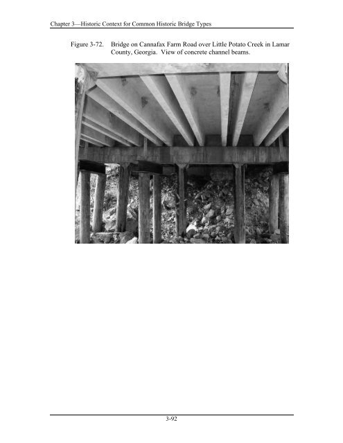
Chapter 3—Historic Context for Common Historic <strong>Bridge</strong> Types Figure 3-72. <strong>Bridge</strong> on Cannafax Farm Road over Little Potato <strong>Creek</strong> in Lamar County, Georgia. View <strong>of</strong> concrete channel beams. 3-92
Chapter 3—Historic Context for Common Historic <strong>Bridge</strong> Types 3.3.5 Reinforced Concrete Girders History and Description: The first reinforced concrete girder bridge was built in France about 1893, and the first <strong>of</strong> the type constructed in the United States appeared in the first decade <strong>of</strong> the twentieth century. In the 1910s, several <strong>of</strong> the early state highway departments issued standardized plans for concrete girder bridges. In 1912, Maryland’s State Roads Commission included a design for a girder bridge in their state’s first standard bridge plans. Although the through girder was common from the 1910s to the 1930s, the type is best suited to short spans from 15 to 40 feet and was not economical for wide roadways <strong>of</strong> more than about 24 feet. Concrete through girder bridges gradually gave way to deck girder designs, as the need for wider roadways increased and concerns about traffic safety rose in the 1930s. In many parts <strong>of</strong> the country during the 1940s, the use <strong>of</strong> concrete girders faded in favor <strong>of</strong> steel I-beam and pre-cast concrete spans due in part to the cost <strong>of</strong> scaffolding and formwork. But, many <strong>of</strong> the concrete girder bridges still in service are deck girder bridges built in the 1940s. Precast reinforced concrete girders were used on a few projects to widen existing cast-in-place concrete girder spans. Another form <strong>of</strong> the concrete girder is the continuous reinforced concrete girder. These began being used by highway departments in the 1950s, pushing span lengths upward to between 50 and 80 feet. This type <strong>of</strong> structure was not used after the late 1960s because <strong>of</strong> the complication <strong>of</strong> falsework and forms, which increased costs and, usually, increased construction time. According to the FHWA <strong>Bridge</strong> Inspector’s Reference Manual (23, p. 7.3.1), reinforced concrete girder bridges (non-prestressed) generally consist <strong>of</strong> cast-in-place, monolithic decks and girder systems. The primary members <strong>of</strong> a girder bridge are the girders, the deck, and, in some cases, floorbeams. The deck or travel surface is cast on top <strong>of</strong> the girders in deck girder bridges, and the deck is cast between the girders in through girder bridges. In either case, the deck slab does not contribute to the strength <strong>of</strong> the girders and only serves to distribute live loads to the girders. If floorbeams are used, they are part <strong>of</strong> the superstructure and not the deck. In through girder bridges, the deck is cast between the girders and the girders extend above the deck, thus forming the bridge’s parapets. This arrangement <strong>of</strong> members makes it virtually impossible to widen a through girder bridge. Most <strong>of</strong> these bridges have now been replaced because their roadway widths were too restrictive for the safety <strong>of</strong> modern traffic. A good example <strong>of</strong> a simple-span concrete through girder bridge from the 1920s is the Main Street-Black River <strong>Bridge</strong> (1923) in Ramsey, Michigan. This bridge is a three-span configuration, with a 50-foot girder above the waterway and 40-foot girders on either end <strong>of</strong> the central span. The Michigan State Highway <strong>Department</strong> first adopted a standard design for concrete through girder bridges in the 1913-1914 biennium. Generally used for span lengths <strong>of</strong> 30 to 40 feet, this design featured a very shallow floor system that provided a maximum clearance above waterways. The Main Street-Black 3-93