I C Precision Altimeter - Farnell
I C Precision Altimeter - Farnell
I C Precision Altimeter - Farnell

Create successful ePaper yourself
Turn your PDF publications into a flip-book with our unique Google optimized e-Paper software.
3.1 I 2 C Interface Characteristics<br />
Table 4. I 2 C Slave Timing Values (1)<br />
Ref Symbol Parameter<br />
I 2 C<br />
Unit<br />
Condition Min Max<br />
1 f SCL SCL Clock Frequency Pull-up = 1 kΩ, C b = 400 pF 0 400 KHz<br />
2 f SCL SCL Clock Frequency Pull-up = 1 kΩ, C b = 20 pF 0 4 MHz<br />
3 t BUF Bus free time between STOP and START condition 1.3 µs<br />
4 t HD;STA Repeated START Hold Time 0.6 µs<br />
5 t SU;STA Repeated START Setup Time 0.6 µs<br />
6 t SU;STO STOP Condition Setup Time 0.6 µs<br />
7 t HD;DAT SDA Data Hold Time (2)<br />
50 (3)<br />
(4)<br />
ns<br />
8 t SU;DAT SDA Setup Time 100 (5)<br />
ns<br />
9 t LOW SCL Clock Low Time 1.3 µs<br />
10 t HIGH SCL Clock High Time 0.6 µs<br />
11 t r SDA and SCL Rise Time 20 + 0.1C b<br />
(6)<br />
300 ns<br />
12 t f SDA and SCL Fall Time (3)(6)(7)(8)<br />
13 t SP<br />
Pulse width of spikes that are suppressed by internal<br />
input filter<br />
20 + 0.1C b<br />
(6) 300 ns<br />
50 ns<br />
1. All values referred to VIH(min) and VIL(max) levels.<br />
2. t HD;DAT is the data hold time that is measured from the falling edge of SCL, applies to data in transmission and the acknowledge.<br />
3. The device must internally provide a hold time of at least 300 ns for the SDA signal (with respect to the VIH(min) of the SCL signal) to bridge<br />
the undefined region of the falling edge of SCL.<br />
4. The maximum t HD;DAT must be less than the maximum of t VD;DAT or t VD;ACK by a transition time. This device does not stretch the LOW period<br />
(t LOW) of the SCL signal.<br />
5. A fast mode I 2 C device can be used in a standard mode I 2 C system, but the requirement t SU;DAT 250 ns must then be met. This will<br />
automatically be the case if the device does not stretch the LOW period of the SCL signal. If such a device does stretch the LOW period of<br />
the SCL signal, it must output the next data bit to the SDA line t r (max) + t SU;DAT = 1000 + 250 = 1250 ns (according to the standard mode<br />
I 2 C specification) before the SCL line is released. Also the acknowledge timing must meet this set-up time.<br />
6. C b = Total capacitance of one bus line in pF.<br />
7. The maximum t f for the SDA and SCL bus lines is specified at 300 ns. The maximum fall time for the SDA output stage t f is specified at<br />
250 ns. This allows series protection resistors to be connected in between the SDA and the SCL pins and the SDA/SCL bus lines without<br />
exceeding the maximum specified t f .<br />
8. In Fast Mode Plus, fall time is specified the same for both output stage and bus timing. If series resistors are used, designers should allow<br />
for this when considering bus timing.<br />
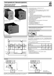
Figure 3. I 2 C Slave Timing Diagram<br />
MPL3115A2<br />
Sensors<br />
Freescale Semiconductor, Inc. 7