for Reliability Report - Public Service Commission
for Reliability Report - Public Service Commission
for Reliability Report - Public Service Commission

You also want an ePaper? Increase the reach of your titles
YUMPU automatically turns print PDFs into web optimized ePapers that Google loves.
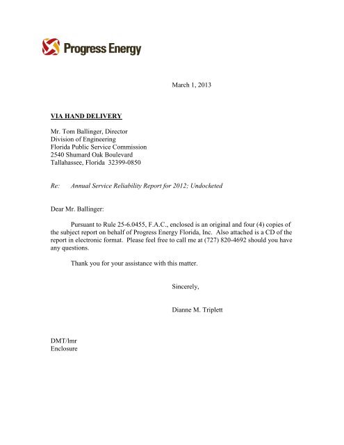
March 1, 2013<br />
VIA HAND DELIVERY<br />
Mr. Tom Ballinger, Director<br />
Division of Engineering<br />
Florida <strong>Public</strong> <strong>Service</strong> <strong>Commission</strong><br />
2540 Shumard Oak Boulevard<br />
Tallahassee, Florida 32399-0850<br />
Re:<br />
Annual <strong>Service</strong> <strong>Reliability</strong> <strong>Report</strong> <strong>for</strong> 2012; Undocketed<br />
Dear Mr. Ballinger:<br />
Pursuant to Rule 25-6.0455, F.A.C., enclosed is an original and four (4) copies of<br />
the subject report on behalf of Progress Energy Florida, Inc. Also attached is a CD of the<br />
report in electronic <strong>for</strong>mat. Please feel free to call me at (727) 820-4692 should you have<br />
any questions.<br />
Thank you <strong>for</strong> your assistance with this matter.<br />
Sincerely,<br />
Dianne M. Triplett<br />
DMT/lmr<br />
Enclosure
~ Progress Energy<br />
2012 Annual <strong>Reliability</strong> <strong>Report</strong><br />
March 1, 2013
Table of Contents<br />
2012 PEF Customer Count by Region .............................................. ........... 2<br />
Overall <strong>Reliability</strong> Per<strong>for</strong>mance - 2012 (Unadjusted) (Rule 25-6.0455, F.A.C.) .. .... .3<br />
Generation Events - Adjustments ............................................... ...... 13<br />
Transmission Events - Adjustments .............................. ...................... 15<br />
Extreme Weather - Exclusions ....................... .. ................. ... ... .... .. .. 16<br />
Other Distribution - Adjustments ............. .. .............................. ......... 18<br />
2012 Adjusted <strong>Reliability</strong> .......................... .......................... .. .. ...... 19<br />
Distribution Substations ......... ... .............. .............................. ........ 27<br />
Supplemental Distribution In<strong>for</strong>mation .............................. ............... 31<br />
<strong>Reliability</strong> Related Customer Complaints ......... ............................ ... ....38<br />
Storm Hardened Facilities ............. ..... ... .................................. .. .. .... .......40<br />
Storm Season Readiness ............................... .. .... .................. ................. 44<br />
Wood Pole Inspection Program .... ..... .. ......................................... ......... ..45<br />
CCA Sampling <strong>Report</strong> .... ..... .. ...... ..... ............... ....................... .. ....... .. ... 46<br />
EIW Initiatives<br />
Vegetation Management (Initiative 1) .................... .. ................... ........48<br />
Joint Use Pole Attachment Audits (Initiative 2) ... ............................ .. .... 54<br />
Transmission Structures- Six Year Inspection Cycle (Initiative 3) .... .. ....... 56<br />
Transmission Structures - Storm Hardening Activities (Initiative 4) ............. 59<br />
Geographic In<strong>for</strong>mation System (GIS) (Initiative 5) ... ............................. 60<br />
Post-Storm Data Collection and Forensic Analysis (Initiative 6) ..... ... .. ........ 63<br />
Overhead/Underground <strong>Reliability</strong> (Initiative 7) ............. .............. .. ....... 67<br />
Coordination with Local Governments (Initiative 8) ................ ...... ... ....... 70<br />
Collaborative Research (Initiative 9) ................. ....... ............... .......... 75<br />
Disaster Preparedness and Recovery Plan (Initiative 10) ............... .... ....... 76<br />
Other Storm Hardening Initiatives (OH/UG)............................. .... ..... .. .... ... .. 78
2012 Year End Customers Served by Region<br />
3 CharOP OP- Center CustServed Date<br />
APK APOPKA 94,012 12/31/2012<br />
DEL DELAND 75,786 12/31/2012<br />
JAM JAMESTOWN 126,024 12/31/2012<br />
LNG LONGWOOD 82,376 12/31/2012<br />
378,198<br />
NORTH COASTAL INV INVERNESS 69,953 12/31/2012<br />
MON MONTICELLO 46,617 12/31/2012<br />
OCA OCALA 76,479 12/31/2012<br />
193,049<br />
SOUTH CENTRAL BNV BUENA VISTA 98,992 12/31/2012<br />
CLR CLERMONT 28,817 12/31/2012<br />
HIL HIGHLANDS 55,712 12/31/2012<br />
LKW LAKE WALES 91,674 12/31/2012<br />
SEO SE ORLANDO 82,149 12/31/2012<br />
WGN WINTER GARDEN 71,547 12/31/2012<br />
428,891<br />
SOUTH COASTAL CLW CLEARWATER 150,825 12/31/2012<br />
SEV SEVEN SPRINGS 167,312 12/31/2012<br />
STP ST. PETERSBURG 161,696 12/31/2012<br />
WAL WALSINGHAM 146,612 12/31/2012<br />
ZEP ZEPHYRHILLS 24,506 12/31/2012<br />
650,951<br />
SYSTEM 1l651l089 12/31/2012<br />
2
I. OVERALL RELIABILITY PERFORMANCE- 2012 (Rule 25-6.0455, F.A.C.)<br />
a. Discuss overall per<strong>for</strong>mance absent adjustments<br />
Please see attached Form i 02. in 20i2, Progress Energy Florida experienced (1)<br />
tornado event and (4) named storms. The four tropical storms, Beryl(5127-5/29),<br />
Debby (6/24-6127), Isaac (8126-8/28) and Sandy (10/26-i0/29) and the tornado that<br />
affected our North Coastal and North Central Zones on i2/i 0 totaled 52.4 minutes.<br />
Please see table below <strong>for</strong> details.<br />
Weather excluded<br />
SAID/<br />
72. 9 6.5 2.5 65.3 52.4<br />
in 20i2, PEF's SAiDi absent adjustments was i42.9, less than 20ii 's per<strong>for</strong>mance<br />
and approximately equal to the average over the last four years. In 20i2, 69.5 total<br />
minutes were excluded, 52.4 of those were severe weather related, as noted in the<br />
table above. The severe weather excluded minutes are 75% of the total minutes<br />
excluded. This percentage is similar to other years that experienced exclusions<br />
related to tropical storms impacting the system. For example, in 2008 the system<br />
experienced Tropical Storm Fay and 74% of the excluded minutes were related to<br />
severe weather. Also, in 20ii PEF's system was impacted by the March 30 1 h event,<br />
which contained properties and extent of damage comparable to that of a tropical<br />
storm. In 20ii, 76% of the excluded minutes were related to severe weather. Even<br />
with similarly impacting weather events on the system, PEF's 20i2 SAID!<br />
per<strong>for</strong>mance was stronger than these two comparable years. This improved<br />
per<strong>for</strong>mance is a result of a continuous focus on reliability projects including, but not<br />
limited to, small wire upgrades, storm hardening, and pole replacements. Please see<br />
table below <strong>for</strong> details.<br />
b. Describe the level of detailed reliability data the Company tracks.<br />
The company tracks detailed reliability in<strong>for</strong>mation in various databases. This<br />
detailed data is recorded per event, which includes affected device, time of day,<br />
length of outage, cause of outage, number of customers affected and other pertinent<br />
in<strong>for</strong>mation.<br />
3
c. Describe Company ef<strong>for</strong>ts to increase critical review of detailed reliability data.<br />
In 2012, PEF continued the use of an internal goal called the Customer <strong>Reliability</strong><br />
Excellence Monitor (CREM). CREM is an index of two system average indices and<br />
two outlier per<strong>for</strong>mance indices. These are measured as SAIDL MAIFie, CEMI4 and<br />
CELID 3 . As discussed in PEF's prior reports, balanced improvement among these<br />
four metrics is targeted to yield higher customer satisfaction.<br />
P EF continued the practice of auditing outage data to ensure accuracy and using<br />
Outage Management System Reconciliation (OMSr) as a plat<strong>for</strong>m which allows<br />
outage data to be captured in greater detail. The OMSr system is an upgrade and<br />
replacement of the previous outage management database.<br />
PEF continued to utilize the <strong>Reliability</strong> Engagement Model that provides a consistent<br />
process and easy to use tools to evaluate individual outages with significant<br />
reliability impact on a daily basis. The Daily <strong>Reliability</strong> Exception <strong>Report</strong> is a daily<br />
report with key outage data at the operations center, region and system level. This<br />
report is intended to help focus the daily engagement ef<strong>for</strong>ts in reliability. The<br />
expectation is to focus on assessing the per<strong>for</strong>mance of the outage restoration ef<strong>for</strong>t<br />
on a real time basis and take the required actions to address all of the identified gaps.<br />
P EF continued to utilize the CEMI device report. The CEMI device report looks at<br />
devices that have gone out four times or more in the given year. This report is<br />
distributed to planning engineers, field personnel, and management <strong>for</strong> review.<br />
Funding is set aside <strong>for</strong> issues that are determined to need addressing immediately<br />
and long term capital projects are identified and submitted <strong>for</strong> approval <strong>for</strong> the<br />
following year. The CEMI premise database looks at CEMI outliers on a<br />
premise/meter level. This database will enable Progress Energy to identify the<br />
specific customers that are not solely affected by one consistently failing device and<br />
would there<strong>for</strong>e not be identified on the CEMI device report.<br />
In 2013, PEFwill begin preliminary implementation ofa<strong>for</strong>mal Outage Follow-up<br />
Process. The purpose of this new initiative is to investigate significant outages in<br />
order to identify the primary root cause and implement engineered solutions to<br />
mitigate the reoccurrence of an event of that nature. The long term goal is to identify<br />
systemic improvements that will enhance a customer 's overall reliability experience.<br />
d. Describe the process used by your company to identify and select the level of<br />
detailed reliability data.<br />
Customer feedback, benchmarking with other utilities, input from the FPSC,<br />
per<strong>for</strong>mance of assets, and trends are all considered when identifying the level of<br />
detailed reliability data.<br />
e. Discuss adjustments<br />
4
1. Generation events - see pages 13 - 14.<br />
n. Transmission events - see page 15.<br />
iii. Distribution events - see page 18.<br />
iv. Extreme weather - see page 16.<br />
f. Discuss adjusted per<strong>for</strong>mance.<br />
For the 2012 adjusted per<strong>for</strong>mance results, please see pages 19 - 25.<br />
5
FLORIDA PUBLIC SERVICE COMMISSION<br />
ANNUAL DISTRIBUTION SERVICE RELIABILITY REPORT- ACTUAL<br />
PART I<br />
CAUSES OF OUTAGE EVENTS- ACTUAL {Absent Adjustments}<br />
Utility Name: Progress Energy Florida Year: 2012<br />
Customer<br />
Average<br />
Minutes<br />
Number Average Restoration<br />
of Outage Duration Time<br />
Cause<br />
Of Events(N) (L-Bar) (CAIDI)<br />
(a) Interruption* (b) (c) (d)<br />
1. Tree-Non Preventable 41,146,088 5,656 206.7 113.7<br />
2. Tree-Preventable 37,812,900 4,626 224.2 140.7<br />
3. Storm 26,429,161 4,627 177.9 144.5<br />
4. Defective Equipment 18,046,297 3,311 188.3 81.5<br />
r ""<br />
U/G Primary Cable 16,506,824 2,183 256.3 92.5<br />
6. Emergency Shutdown-PGN 14,432,784 935 171.4 40.6<br />
7. Connector Failure 11,826,927 3,118 129.6 93.6<br />
8. Line Maintenance 9,178,828 5,595 145.1 130.5<br />
9. Vehicle/Canst Equipment 8,614,950 316 247.4 85.9<br />
10. Unknown 7,430,245 3,145 102.5 84.8<br />
Subtotal 191 ,425,004 33 ,512 178.7 98.0<br />
All Other Causes *See Pages 7 -10 44,493,219 15,680 132.9 70.9<br />
<strong>for</strong> breakdown of All Other Causes<br />
System Totals 235,918,218 49,192 164.1 91.4<br />
*Since the causes are ranked by CMI, a CMI column was added to this chart in order to<br />
clearly see the rankings.<br />
PSC/ECR 102 (8/06)<br />
Incorporated by reference in Rule 25-6.0455, F.A.C.<br />
6
)-l:\USES OF OUTAGE EVENTS- ACTUAL {Absent Adjustments}<br />
Utility Name: Progress Energy Florida Year: 2012<br />
I<br />
All Other Causes Customer Average<br />
Minutes<br />
Number Average Restoration<br />
of Outage<br />
Duration<br />
Of<br />
Time<br />
Cause Events(N) (L-Bar)<br />
(CAIDI)<br />
(a) Interruption (b) (c)<br />
(d)<br />
Lightning<br />
Animal<br />
Wind<br />
Substation-Breaker Failure<br />
U/G Secondary/<strong>Service</strong><br />
Birds<br />
Emergency Shutdown-<br />
Customer Request<br />
Substation-Breaker-<br />
Preventable<br />
Relay-Relay Problem<br />
Human Error- PGN<br />
Contractor<br />
Overload<br />
Right-of-Way<br />
Miscellaneous<br />
System Undetermined<br />
6,508,636 1,078 195.5 91.0<br />
5,699,852 6,331 70.4 63 .1<br />
5,146,284 423 518.3 254.6<br />
3,101 ,727 78 1 ' 130.2 611.5<br />
2,840,341 30 88.7 66.7<br />
2,192,296 3,860 183.5 411.5<br />
2,077,103 490 91.6 51.2<br />
1,949,093 26 58.1 33.9<br />
1,471,070 14 70.4 68.0<br />
1,173,930 84 154.9 55 .9<br />
1,148,226 200 142.7 64.0<br />
1,078,467 27 34.5 25.6<br />
1,056,758 128 323.3 231 .6<br />
997,680 69 36.4 61.0<br />
Dig-In 906,046 326 21 3.8 64.9<br />
Human Error- PGN<br />
794,257 743 62.5 30.6<br />
Substation-Unknown<br />
769,812 15 152.0 60.0<br />
Human Error- <strong>Public</strong><br />
679,837 218 133. 1 79.1<br />
Corrosion<br />
473,312 208 194.7 159.5<br />
Substation-Breaker-Non<br />
424,169 4 99.0 73.6<br />
Preventable<br />
-... Relay-Equipment<br />
395,014 6 31.9 31.7<br />
Misapplication<br />
7
CAUSES OF OUTAGE EVENTS - {Absent Adjustments}<br />
Utility Name: Progress Energy Florida<br />
Year:2012<br />
All Other Causes Customer Average Restoration<br />
Minutes<br />
Number<br />
Average<br />
Time<br />
of Outage<br />
Duration<br />
Of<br />
(CAIDI)<br />
Cause Events(N) (L-Bar)<br />
(d)<br />
(a) Interruption (b) (c)<br />
Transmission-Lightening<br />
Relay-Human Error-PGN<br />
Foreign Material in Line<br />
Substation-Animal<br />
Relay-Wiring Error<br />
Relay-Incorrect Setting<br />
Applied<br />
Transmission-<br />
Conductor/Static<br />
Relay-Foreign Material In<br />
" }lay<br />
Transmission-Tree-Non<br />
Preventable<br />
Relay-Setting Error<br />
Construction Equipment<br />
Substation-Lightning<br />
Substation-Trans<strong>for</strong>mer<br />
Failure<br />
366,823 7 88.6 90.4<br />
355,509 4 156.8 55.6<br />
300,905 62 142.1 52.7<br />
239,257 4 106.3 80.5<br />
228,029 3 54.0 53.9<br />
211,890 8 23.8 23.8<br />
178,066 3 65.8 60.0<br />
159,489 2 26.6 27.0<br />
148,476 2 313.7 134.7<br />
129,487 6 34.6 28.9<br />
126,758 16 154.5 34.5<br />
118,783 1 239.0 239.0<br />
115,797 3 41.0 41 .0<br />
Substation-Switch Failure 106,974 4 13.5 21 .8<br />
0/H Secondary Cable<br />
106,414 348 129.5 130.7<br />
T ransm ission-Eq ui p<br />
104,432 1 210.6 125.4<br />
Misapplication<br />
Substation-Current<br />
85,444 1 40.7 41 .0<br />
Trans<strong>for</strong>mer<br />
8
CAUSES OF OUTAGE EVENTS - {Absent Adjustments}<br />
Utility Name: Progress Energy Florida<br />
Year:2012<br />
All Other Causes Customer Average<br />
Number Average Restoration<br />
Minutes<br />
of Outage<br />
Duration<br />
Time<br />
Cause Of<br />
Events(N) (L-Bar)<br />
(CAIDI)<br />
(a) Interruption (b) (c)<br />
(d)<br />
Vandalism<br />
Substation-Switch Error-<br />
Sub<br />
Transmission - Unknown<br />
Substation-Defective<br />
Equipment<br />
Transmission-Human Err-<br />
Contractor<br />
83 ,332 127 72.9 17.3<br />
76,608 1 112.1 112.0<br />
76,236 1 87.2 44.6<br />
54,001 8 8.8 6.6<br />
44,323 2 41.7 20.0<br />
Transmission-Cross arm<br />
40,693 2 46.0 62.9<br />
Failure<br />
J ....<br />
jproper Installation<br />
37,098 28 117.0 106.6<br />
Equipment Misapplication<br />
Transmission-Insulator<br />
Failure<br />
Relay-Reclosing Relay<br />
Failure<br />
Customer Request<br />
Substation-Planned<br />
Outages<br />
Voltages OK at Meter-No<br />
Customer Contact<br />
31 ,901 12 88.3 63.2<br />
15,884 2 9.4 9.6<br />
15,780 1 12.0 12.0<br />
15,236 25 83 .0 25 .5<br />
11 ,224 4 116.0 8.2<br />
9,147 520 11.9 14.8<br />
Relay-System Operation 4,529 0 0 7.0<br />
Transmission-Human 3,703 2 45.3 19.1<br />
Error-PGN<br />
Inaccessible Meter<br />
Relay-External Control<br />
SCAD A<br />
........<br />
2,458 97 25.4 21.9<br />
1,707 I 2.9 3.0<br />
9
)-- CAUSES OF OUTAGE EVENTS - {Absent Adjustments}<br />
Utility Name: Progress Energy Florida<br />
Year:2012<br />
All Other Causes Customer Average<br />
Minutes<br />
Number Average Restoration<br />
of Outage<br />
Duration<br />
Time<br />
Cause Of Events(N) (L-Bar)<br />
(CAIDI)<br />
(a) Interruption (b) (c)<br />
(d)<br />
Relay-Unknown<br />
1,596 1 52.2 29.6<br />
0/H <strong>Service</strong> Cable<br />
1,3 15 13 101.1 101.2<br />
Other Causes<br />
44,493,214 15,680 132.9 70.9<br />
10
THREE PERCENT FEEDER LIST - ACTU~ {UNADJUSTED)<br />
Utility Name: Progress Energy Florida Year: 2012<br />
- - I --<br />
1-'<br />
1-'<br />
Primary<br />
C ircu~<br />
ld. No.<br />
or Name<br />
(a)<br />
N64<br />
N231<br />
K779<br />
WOIOS<br />
C4501<br />
M579<br />
A78<br />
W0629<br />
Xl34<br />
M657<br />
N38<br />
A32 1<br />
Nl<br />
X132<br />
N58<br />
C305<br />
W0029<br />
C4001<br />
AS I<br />
N43<br />
Sub-station<br />
Origin<br />
(b)<br />
WAUKEENAH<br />
EASTPOINT<br />
ISLESWORTii<br />
CANOE CREEK<br />
SEVEN SPRINGS<br />
ALTAMONTE<br />
INGLIS<br />
HOLOPAW<br />
CROSSROADS<br />
MYRTLE LAKE<br />
OCHLOCKNEE<br />
WEIRSDALE<br />
MADISON<br />
CROSSROADS<br />
APALACHICOLA<br />
TARPON SPRINGS<br />
CASSELBERRY<br />
FLORA MAR<br />
MCINTOSH<br />
CARRABELLE<br />
MONTICELLO<br />
MONTICELLO<br />
BUENA VISTA<br />
CONWAY<br />
N48<br />
CARRABELLE BEACH MONTICELLO<br />
!240 ULMER TON<br />
WALSINGHA1"1<br />
M45 1<br />
BAY RIDGE<br />
APOPKA<br />
AI 54<br />
SILVER SPRINGS OCALA<br />
A205<br />
ZUBER<br />
OCALA<br />
A98<br />
BROOKSVILLE INVER.,'IESS<br />
A45<br />
GEORGIA PACIFIC OCALA<br />
Al 95<br />
ARCHER<br />
OCALA<br />
Al24<br />
WILLISTON<br />
INVERNESS<br />
Xl20<br />
GATEWAY<br />
WALSINGHAM<br />
A202<br />
ZUBER<br />
OCALA<br />
A21 2<br />
TROPIC TERRACE INVERNESS<br />
Ai lS<br />
CROSS CITY<br />
OCALA<br />
W0630<br />
HOLOPAW<br />
CONWAY<br />
ASO<br />
MCINTOSH<br />
OCALA<br />
X1 36<br />
CROSSROADS ST. PETERSBURG<br />
C2805<br />
HIGHLANDS CLEARWATER<br />
A39<br />
MARTIN<br />
OCALA<br />
J890<br />
SEMINOLE<br />
WALSINGHAM<br />
C8<br />
CLEARWATER CLEARWATER<br />
LBAR AND CAIDIIncludes all devices.<br />
PSC/ECR 102 (8/06)<br />
lncoroorated bv reference in Rule 25-6.0455. F.A.C.<br />
Location<br />
(c)<br />
SEVEN SPRINGS<br />
LONGWOOD<br />
INVERNESS<br />
CONWAY<br />
ST. PETERSBURG<br />
LONGWOOD<br />
MONTICELLO<br />
OCALA<br />
MONTICELLO<br />
ST. PETERSBURG<br />
MOl'.'TICELLO<br />
SEVEN SPRINGS<br />
LONGWOOD<br />
SEVEN SPRINGS<br />
OCALA<br />
MONTICELLO<br />
Number of Customers<br />
Outage No. of Corrective<br />
Events Avg Listed Last Year? Years Action<br />
"N" Duration (I) in the Completion<br />
Residential Commercial Industrial Other Total "L-Bar" CAIDI LastS Date<br />
(d) (e) (f) {g)<br />
(h) (I) 0) (k) (m) (n)<br />
499 110 2<br />
12 623 9 229.9 144.2 N 6/30113<br />
772 137 I<br />
I 911 9 333.6 98.7 N 2 6130/ 13<br />
935 89<br />
1.024 7 148.6 53.6 N 6130/13<br />
449 118<br />
567 6 144.9 87.6 y 3 4/26/11<br />
1.960 164<br />
2.124 6 245.7 171.1 N I 3/28/1 2<br />
1.651 271 I<br />
I 1.924 6 149.4 56.2 N I 9/28111<br />
1.070 133 5<br />
5 1.213 6 127.1 56.0 N . 9/30112<br />
803 234 10<br />
10 1.057 6 150.4 103.4 y 2 6130/13<br />
1.366 257<br />
1.623 5 84.1 84 I N - 6/30/13<br />
767 53<br />
820 5 311.6 37.2 y 2 5/ I/12<br />
889 51<br />
940 5 164.7 205.4 N - 5/18/12<br />
1.435 119 2<br />
2 1.558 5 117.3 96.2 N 7/27/1 2<br />
905 129<br />
1.034 5 118.3 92.8 N I 1/12/12<br />
680 ISS 4<br />
4 843 5 108.1 35.1 N 6130/13<br />
630 206 9<br />
9 854 5 279.5 120.1 N 2 6130/13<br />
1.610 272 II<br />
II 1.904 5 174.7 41.3 N 6130/13<br />
696 61<br />
757 5 182.6 137.4 N 6/30/13<br />
1.812 274<br />
2.086 5 132.8 29.1 N 6130/13<br />
1.066 182 4<br />
4 1.256 5 178.9 107.2 y I 6130/13<br />
1.429 158 I<br />
I 1.589 4 610.0 428.8 N 5/18112<br />
518 89<br />
607 4 445.7 266.8 N I 3/2/12<br />
213 244 17<br />
17 491 4 185.4 150.2 N 6130/13<br />
1.1 92 167 2<br />
2 1.363 4 129.5 126.1 N 6130113<br />
719 144 3<br />
3 869 4 119.3 118.5 y I 5/ 1/12<br />
1.288 191 2<br />
2 1.483 4 157.4 116.0 N 6/30/ 13<br />
1.129 158 I<br />
I 1.289 4 187.3 115.0 N 6/30/13<br />
938 247<br />
1.185 4 106.9 1061 N 6130/13<br />
I 2<br />
2 5 4 106.0 106.0 N I 6130/13<br />
1,590 138<br />
1.728 4 125.3 103.1 N 10/12/12<br />
1.456 223 20<br />
20 1.719 4 124.7 101.7 N 6130/13<br />
987 193 6<br />
6 1.192 4 164.3 100.1 N 7127/ 12<br />
1.024 248 I<br />
I 1.274 4 147.2 99.1 N 6130/13<br />
672 148 2<br />
2 824 4 119.4 93.9 N 6130/13<br />
584 60<br />
644 4 197.1 89.3 N 6130/ 13<br />
678 133 3<br />
3 817 4 127.2 63.8 N 6130/13<br />
479 16 I<br />
I 497 4 138.3 56.4 N 6130/13<br />
2.852 100<br />
2.952 4 210.5 55.5 N - 6130/13<br />
349 116<br />
465 4 144.3 54.9 N I 4/26/1 1<br />
2.282 250<br />
2.532 4 211.3 53.8 N 6130/ 13<br />
251 78<br />
329 4 176.9 52.2 N 6130/13
PART Ill<br />
SYSTEM RELIABILITY INDICES- ACTUAL {ABSENT ADJUSTMENTS)<br />
Utility Name: Progress Energy Florida Year: 2012<br />
District or<br />
<strong>Service</strong> Area SAIDI CAIDI SAIFI MAl Fie CEMIS<br />
(a) (b) (c) (d) (e) (f)<br />
North Coastal 344.0 138.5 2.48 8.9 11.64%<br />
I I I I I I<br />
Inverness 206.1 96.5 2.14 10.8 6.89%<br />
Monticello 778.5 221.3 3.52 9.1 22.52%<br />
Ocala 205.3 94.5 2.17 7.1 9.35%<br />
South Coastal 144.8 90.3 1.60 10.5 1.81%<br />
Clearwater 115.8 71.8 1.61 11.3 1.51 %<br />
Seven Springs 144.7 84.5 1.71 10.1 2.70%<br />
St. Petersburg 169.1 99.0 1.71 10.8 2.04%<br />
Walsingham 162.6 109.8 1.48 9.9 1.15%<br />
Zephyrhills 57.1 68.2 0.84 10.4 0.05%<br />
North Central 107.4 74.3 1.45 9.9 1.85%<br />
Apopka 109.6 72.9 1.50 12.2 1.73%<br />
Deland 115.2 68.3 1.69 9.1 2.69%<br />
Jamestown 88.4 77.1 1.15 8.5 0.35%<br />
Longwood 126.9 78.5 1.62 10.0 3.50%<br />
South Central 80.8 67.8 1.19 7.8 1.36%<br />
Buena Vista 64.7 75 .2 0.86 5.3 0.06%<br />
Clermont<br />
62.8 59.2 1.06 8.9 1.64%<br />
SE Orlando 109.1 67.4 1.62 6.2 4.09%<br />
Highlands<br />
91.1 59.7 1.52 9.5 0.47%<br />
Lake Wales<br />
70.9 66.6 1.06 9.2 0.47%<br />
Winter Garden<br />
82.3 73.8 1.11 9.4 1.75%<br />
SYSTEM 142.9 91.4 1.56 9.5 2.85%<br />
PSC/ECR 1 02 (8/06)<br />
Incorporated by reference in Rule 25-6.0455, F.A.C.<br />
12
GENERATION EVENTS- ADJUSTMENTS (Rule 25-6.0455 F.A.C.)<br />
a. Discuss each generation event that resulted in customer outages.<br />
There were no events to report <strong>for</strong> 2012.<br />
b. Address whether the event was localized or system-wide.<br />
N/A<br />
c. Describe the Company's ef<strong>for</strong>ts to avoid or minimize any similar events in the<br />
future in terms of the level of costs incurred and outage duration.<br />
N/A<br />
d. Provide the 2012 service reliability data <strong>for</strong> each generation outage event that is<br />
excluded from your Company's 2012 Annual Distribution <strong>Reliability</strong> <strong>Report</strong><br />
pursuant to Rule 25-6.0455.<br />
Generation Event<br />
c<br />
CMI<br />
CI<br />
SAID I<br />
SAIFI<br />
N/A<br />
N/A<br />
N/A<br />
N/A<br />
N/A<br />
N/A<br />
Please see attached Form 103.<br />
13
PART I<br />
CAUSES OF OUTAGE EVENTS - ADJUSTED<br />
Utility Name: Progress Energy Florida Year: 2012<br />
Average<br />
Number Average Restoration<br />
of Outage Duration Time<br />
Cause Events(N) (L-Bar) (CAIDI)<br />
(a) (b) (c) (d)<br />
Generation N/A N/A N/A<br />
System Totals: N/A N/A N/A<br />
PSC/ECR 103 (8/06)<br />
Incorporated by reference in Rule 25-6.0455, F.A.C.<br />
14
TRANSMISSION EVENTS- ADJUSTMENTS (Rule 25-6.0455 F.A.C.)<br />
a. Discuss each transmission event that resulted in customer outages.<br />
See Attachment A - "PEF Transmission Outages 2012- Major Events Excluded".<br />
b. Address whether the event was localized or system-wide.<br />
See Attachment A- "PEF Transmission Outages 2012- Major Events Excluded".<br />
c. Describe the Company's ef<strong>for</strong>ts to avoid or minimize any similar events in the<br />
future in terms of the level of costs incurred and outage duration.<br />
Outages that are less than 500,000 customer minutes are reviewed and investigated<br />
by local transmission maintenance staff The results from these investigations are<br />
looked at from a system perspective by Progress Energy Florida 's Transmission<br />
Department Asset Management Group to determine if the failure is isolated or similar<br />
failures are occurring on another part of the system. When similar failures are noted<br />
on the system, further investigation is per<strong>for</strong>med to determine if a solution should be<br />
implemented system wide to remedy the problem. If a project is required, it is<br />
submitted <strong>for</strong> prioritization against other projects.<br />
If the outage exceeds 500,000 customer minutes, a team is assembled to per<strong>for</strong>m a<br />
root cause investigation. The root cause investigation will identify corrective actions<br />
needed to prevent repeat occurrences. If a project is required, it is submitted <strong>for</strong><br />
prioritization against other projects.<br />
d. Provide the 2012 service reliability data <strong>for</strong> each generation outage event that is<br />
excluded from your Company's 2012 Annual Distribution <strong>Reliability</strong> <strong>Report</strong><br />
pursuant to Rule 25-6.0455<br />
See Attachment B - "P EF Transmission Outages 2012 -Major Events Only".<br />
15
EXTREME WEATHER- EXCLUSIONS (Rule 25-6.0455 F.A.C.)<br />
a. Include in the discussion, the type of weather event, strength (wind speeds/surgeflood<br />
levels), locations affected, source of meteorological in<strong>for</strong>mation, and the<br />
per<strong>for</strong>mance of overhead and underground systems.<br />
Distribution<br />
See Attachment C- "Summary of Severe Weather Dates - 2012 ".<br />
Transmission<br />
See Attachment B- "PEF Transmission Outages 2012- Major Events Only".<br />
b. Describe the Company's ef<strong>for</strong>ts to avoid or minimize in terms of costs incurred<br />
and outage duration any similar events in the future (Example: Reference<br />
specific storm hardening activity)<br />
Distribution<br />
Please see response to "Storm Hardened Facilities " on Page 40. These ef<strong>for</strong>ts are<br />
also addressed in our approved Storm Hardening Plan that was filed on May 3, 2010<br />
(Attachment J).<br />
Transmission<br />
Please see response to "Storm Hardened Facilities " on Page 40. These ef<strong>for</strong>ts are<br />
also addressed in our approved Storm Hardening Plan that was filed on May 3, 2010<br />
(Attachment J).<br />
c. If the method of deriving the weather exclusion is different from the method<br />
used <strong>for</strong> 2010, please explain the changes and provide the CMI and CI <strong>for</strong> 2011<br />
using the prior method.<br />
For Distribution & Transmission - The exclusion method used is the same f or 2005,<br />
2006, 2007, 2008, 2009, 2010, 2011 and 2012.<br />
16
d. Provide the 2012 service reliability data <strong>for</strong> each extreme weather outage event<br />
that is excluded from your Company's 2012 Annual Distribution <strong>Reliability</strong><br />
<strong>Report</strong> pursuant to Rule 25-6.0455.<br />
Distribution<br />
Overhead vs.<br />
Dates Underground c CMI Cl Duration L-Bar<br />
May 27 - May 29 Overhead 1,651,089 2,272,331 34,681 59,070 114.7<br />
UnderQround 185,275 1,413 17,552 190.8<br />
N<br />
515<br />
92<br />
Jun 24 - Jun 27 Overhead 1,651,089 74,299,761 257,577 1,903,876 616.5<br />
Underaround 4,174,386 10,181 235,945 526.7<br />
3,088<br />
448<br />
Aug 26 to Aug 28 Overhead 1,651,089 2,404,278 32,582 77,816 124.7<br />
UnderQround 156,209 1,431 15,414 142.7<br />
624<br />
108<br />
Oct 26 to Oct 29 Overhead 1,651 ,089 2,764,967 38,956 68,160 125.3<br />
Underaround 143,751 1,551 15,440 133.1<br />
544<br />
116<br />
Dec 10 Overhead 169,798 62,981 1,482 659 73.2<br />
UnderQround - - - -<br />
9<br />
-<br />
Transmission<br />
See Attachment B- "PEF Transmission Outages 2012- Major Events Only".<br />
17
OTHER DISTRIBUTION- ADJUSTMENTS (Rule 25-6.0455, F.A.C.)<br />
a. Discuss the causation of each type of distribution event that resulted in customer<br />
complaints.<br />
Since Progress Energy Florida has not taken other causations as exclusions <strong>for</strong> any<br />
events in 2012, PEF has no in<strong>for</strong>mation to report in this section.<br />
b. Describe the Company's ef<strong>for</strong>ts to avoid or minimize any similar events in the<br />
future in terms of the level of costs incurred and outage duration.<br />
Since Progress Energy Florida has not taken other causations as exclusions <strong>for</strong> any<br />
events in 2012, PEF has no in<strong>for</strong>mation to report in this section.<br />
c. Provide the 2012 service reliability data <strong>for</strong> each distribution outage event that is<br />
excluded from your Company's 2012 Annual Distribution <strong>Reliability</strong> <strong>Report</strong><br />
pursuant to Rule 25-6.0455<br />
1. A table<br />
n. Electronic file<br />
n1. Causation, Date, CMI, CI Total Repair Cost, etc.<br />
Since Progress Energy Florida has not taken other causations as exclusions <strong>for</strong> any<br />
events in 2012, PEF has no in<strong>for</strong>mation to report in this section.<br />
18
2012 ADJUSTED RELIABILITY (Rule 25-6.0455, F.A.C.)<br />
Progress Energy Florida 's 2012 annual adjusted SA1Dl is the lowest since PEF has been<br />
recording reliability per<strong>for</strong>mance goals. PEF's increased focus on reliability improvement<br />
projects in the North Coastal Region during 2011 and 2012 significantly improved the<br />
customer 's overall reliability experience. Further evidence on the improved reliability across<br />
PEF's service territory is the reduction of customer initiated complaints to the lowest level<br />
observed in 9 years. This per<strong>for</strong>mance validates the processes and analytical techniques to<br />
target projects and maintenance <strong>for</strong> continuous reliability improvement. PEF's annual adjusted<br />
reliability goal per<strong>for</strong>mance always includes a degree of variability due to the number of<br />
confirmed tornadoes affecting PEF service territory. PEF's consistent adherence to the PSC<br />
guidelines to only exclude confirmed tornadoes may have a negative impact on adjusted<br />
reliability indices if tornadoes are not confirmed by the National Weather <strong>Service</strong> (NWS).<br />
During the previous three years there has been an increase in severe storms that quickly<br />
materialize into major weather events. These events were not excludable under F.A. C guidelines<br />
and PEF's SAID! was severely impacted in those years. PEF's service territory did not<br />
experience any of these type events in 2012. As a result, PEF's SAIDI in 2012 was comparable<br />
to 2007 and 2008 per<strong>for</strong>mance, as per the table below, prior to the occurrence of these erratic<br />
weather events.<br />
}'ear 200 7 2008 2009 20 /(} 20 II 2012<br />
Adjusted SAJDJ 78.3 75.7 82.8 93.3 86.9 73.4<br />
a. Causes of outages events- see attached <strong>for</strong>ms.<br />
i. 5-yr patterns/trends in outage causation <strong>for</strong> each of the top 10 causes of<br />
outage events, including the frequency, duration, restoration time, cost<br />
incurred to restore service, remediation programs and costs.<br />
• See Attachment D - "5 yr Trend by Cause Code " Spreadsheet <strong>for</strong> 2008 -<br />
2012.<br />
ii. The process used to identify and select the actions to improve the<br />
per<strong>for</strong>mance in each of the top 10 causes of outages.<br />
PEF prioritizes the reliability improvement action plan by balancing<br />
historical and current year per<strong>for</strong>mance. System devices are evaluated based<br />
on the number of interruptions, customers interrupted (CI), and customer<br />
minutes of interruption (CMI). In addition, current year per<strong>for</strong>mance is<br />
monitored monthly to identifY emergent and seasonal issues including load<br />
balancing <strong>for</strong> cold weather and the need <strong>for</strong> foot patrols of devices<br />
experiencing multiple interruptions.<br />
iii. 2012 activities and budget levels addressing each of the 10 causes of<br />
service outage.<br />
19
• See Attachment E- "2013 Program Budget" Spreadsheet ".<br />
b. Three percent Feeder list<br />
i. Identify whether any feeders appear on the 3% listing more than once<br />
within a consecutive 5-yr. period and any actions implemented to<br />
improve feeder per<strong>for</strong>mance.<br />
• See attached <strong>for</strong>m on Page 24.<br />
ii. The process used to identify and select the actions to improve the<br />
per<strong>for</strong>mance of feeders in the 3% feeder list, if any.<br />
P EF prioritizes the reliability improvement action plan <strong>for</strong> 3% Feeder List by<br />
balancing historical and current year per<strong>for</strong>mance. Feeders are evaluated<br />
based on the number of interruptions, customers interrupted (CI), and<br />
customer minutes of interruption (CMI). In addition, current year<br />
per<strong>for</strong>mance is monitored monthly to identify emergent and seasonal issues<br />
including load balancing <strong>for</strong> cold weather and the need <strong>for</strong> foot patrols of<br />
feeders experiencing multiple interruptions.<br />
iii. 2013 activities and budget levels directed at improving feeder<br />
per<strong>for</strong>mance.<br />
Feeders are prioritized <strong>for</strong> maintenance and replacement work based on<br />
several criteria including customer minutes of interruption (CMJ), number of<br />
interruptions, interruption cause code, and CEMI repeat outage per<strong>for</strong>mance.<br />
This process results in a work plan targeted atfeeders and devices having the<br />
greatest impact on reliability indices and customer satisfaction. This process<br />
has resulted in consistent and sustained reliability per<strong>for</strong>mance.<br />
The 3% feeder list is based solely on number of interruptions and does not<br />
take into consideration any of the additional criteria above. While all feeders<br />
on the 3% list are patrolled <strong>for</strong> corrective action, the possibility exists that<br />
they could appear on the list more than once due to their relative impact on<br />
system reliability indices.<br />
For the 2013 budget levels, please see Attachment E- "2013 Program<br />
Budget" Spreadsheet.<br />
c. Regional <strong>Reliability</strong> Indices -see attached <strong>for</strong>ms.<br />
i. 5-Yr. patterns/trends in each regions reliability <strong>for</strong> each index and on any<br />
overall basis.<br />
• See Attachment F- "5 yr Sum by Region " Spreadsheet.<br />
20
n. The process used to identify and select actions to improve the regional<br />
reliability trends.<br />
• Regional reliability trends are tracked to ensure alignment with the system<br />
level goals they support. Specific device level improvements are measured<br />
and prioritized at a system level to ensure maximum benefit <strong>for</strong> resources<br />
expended.<br />
iii. Discuss any 2013 projected activities and budget levels directed at<br />
improving regional reliability per<strong>for</strong>mance.<br />
• See Attachment E- "2013 Program Budget " Spreadsheet. Regional<br />
reliability trends are tracked to ensure alignment with the system level<br />
goals they support. Specific device level improvements are measured and<br />
prioritized at a system level to ensure maximum benefit <strong>for</strong> resources<br />
expended.<br />
• In 2013, P EF will begin preliminary implementation of a <strong>for</strong>mal Outage<br />
Follow-up Process. The purpose of this new initiative is to investigate<br />
significant outages in order to identify the primary root cause and<br />
implement engineered solutions to mitigate the reoccurrence of an event of<br />
that nature. The long term goal is to identify systemic improvements that<br />
will enhance a customer 's overall reliability experience.<br />
21
FLORIDA PUBLIC SERVICE COMMISSION<br />
ANNUAL DISTRIBUTION SERVICE RELIABILITY REPORT<br />
ADJUSTED<br />
PART I<br />
CAUSES OF OUTAGE EVENTS - ADJUSTED<br />
Utility Name: Progress Energy Florida<br />
Year:2012<br />
Customer<br />
Average Restoration<br />
Minutes<br />
Number Average Time<br />
of Outage Duration (CAIDI)<br />
Cause Of Events(N) (L-Bar) (d)<br />
(a) Interruption* (b) (c)<br />
1.) Tree-Non Preventable 24,469,699 4,438 150.4 87.0<br />
2.) Defective Equipment 15,801 ,940 3,122 177.3 76.4<br />
3.) U/G Primary Cable 14,908,936 2,076 252.2 88.7<br />
4.) Tree-Preventable 14,183,243 3,229 120.1 76.5<br />
5.) Connector Failure 10,534,776 2,892 114.3 89.5<br />
6.) Storm 8,570,099 3,826 102.9 85.3<br />
7.) Vehicle/Const Equip 8,2 16,261 303 239.2 84.6<br />
8.) Animal 5,476,469 6,168 69.5 62.3<br />
9.) Lightning 4,856,314 980 191.5 78.7<br />
1 0.) Unknown 4,062,705 2,909 80.1 56.4<br />
Subtotal 111 ,080,442 29,943 126.2 80.6<br />
All Other Causes *See Page 10,145,327 6,577 143.3 51.0<br />
23 <strong>for</strong> breakdown of All Other<br />
Causes<br />
System Totals: 121,225,769 36,520 129.3 76.8<br />
* Since the causes are ranked by CMI, a CMI column was added to this chart in order to<br />
clearly see the rankings.<br />
PSC/ECR 103 (8/06)<br />
Incorporated by reference in Rule 25-6.0455, F.A.C.<br />
22
'<br />
CAUSES OF OUTAGE EVENTS- ADJUSTED<br />
Utility Name: Progress Energy Florida<br />
Year:2012<br />
All Other Causes Customer Average Restoration<br />
Minutes<br />
Number Average Time<br />
of Outage Duration (CAIDI)<br />
Cause<br />
Of Events(N) (L-Bar) (d)<br />
(a) Interruption (b) (c)<br />
Birds 2,036,951 469 90.6 50.6<br />
Overload 1,142,106 196 139.3 63 .9<br />
Human Error-PGN<br />
Contractor<br />
981,990 82 142.9 47.3<br />
Right-Of-Way 940,161 26 34.2 24.2<br />
Wind 929,834 168 129.5 98.8<br />
Dig-In 884,754 319 211.4 63 .7<br />
U/G Secondary/<strong>Service</strong> 835,372 3,642 168.4 183.5<br />
lJ;;4Jman Error-PGN 790,039 726 62.1 30.6<br />
numan Error-<strong>Public</strong> 626,008 206 128.4 79.6<br />
Corrosion 303,720 160 150.9 113.1<br />
Miscellaneous 210,294 37 81.1 72.0<br />
Foreign Material In Line 158,558 46 78.1 35.3<br />
Construction Equipment 108,315 15 132.1 29.9<br />
Vandalism 83 ,004 124 72.9 17.2<br />
0/H Secondary Cable 51,490 316 125.7 125.9<br />
Equipment Misapplication 31 ,745 11 94.0 63 .9<br />
Improper Installation 29,786 22 104.2 91.9<br />
0/H <strong>Service</strong> Cable 1,200 12 100.0 100.0<br />
All Other Causes 10,145,327 6,577 143 .3 51.0<br />
23
PART II<br />
THREE PERCENT FEEDER LIST - ADJUSTED<br />
Utility Name: PROGRESS ENERGY FLORIDA, INC. Year: 2012<br />
N<br />
~<br />
NUMBER OF CUSTOMERS<br />
PRIMARY CIRCUIT I D.<br />
NO. OR NAME SUBSTATION OUTAGE<br />
ORIGIN LOCATION RESI DENTIAL COMM ERCIAL IN DUSTRIAL OTHER TOTAL EVENTS<br />
(a) (b) (c) (d) (e) (f) (g) (h) (i)<br />
M579 ALTAMONTE LONGWOOD 1.651 271 I 22 1.945 6<br />
A321 WEIRSDALE OCALA 1.435 119 2 16 1.572 5<br />
N64 WAUKEENAH MONTICELLO 499 110 2 12 623 5<br />
K779 ISLES WORTH WINTER GARDEN 935 89 13 1.037 4<br />
M657 MYRTLE LAKE LONGWOOD 767 53 3 823 3<br />
W0523 CASSADAGA DELAN D 1.305 17 15 1.337 3<br />
247 ULMER TON WALSINGHAM 336 3 69 408 3<br />
W0629 HOLOPAW CONWAY 803 234 10 21 1.068 3<br />
Xl32 CROSSROADS ST. PETERSBURG 680 155 4 14 853 3<br />
C4989 CURLEW SEVEN SPRINGS 2.220 Ill 3 2.334 3<br />
K957 BOGGY MARSH BUENA VISTA 2.002 137 13 2.152 3<br />
A212 TROPIC TERRACE INVERNESS 1.024 248 I 34 1.307 3<br />
WOOI7 CASSELBERRY JAMESTOWN 1.489 21 7 1.51 7 3<br />
WII08 DELAND EAST DELAND 1.835 108 I 17 1.961 3<br />
C I03 DUNEDIN CLEARWATER 2.792 169 31 2.992 3<br />
K4841 MONTVERDE CLERMONT 1,503 66 4 14 1.587 3<br />
"4501 SEVEN SPRINGS SEVEN SPRINGS 1.960 164 14 2.138 3<br />
Ml03 WEKIVA APOPKA 308 248 12 568 3<br />
A39 MARTIN OCALA 349 116 30 495 3<br />
X1 20 GATEWAY WALS INGHAM 1,456 223 20 32 1.731 3<br />
WOI76 OVIEDO JAMESTOWN 1.530 43 10 1.583 3<br />
W0029 CASSELBERRY JAMESTOWN 696 61 19 776 3<br />
Al24 WILLISTON OCALA 1.590 138 3 1.731 3<br />
C8 CLEARWATER CLEARWATER 251 78 II 340 3<br />
M445 BAY RIDGE APOPKA 520 131 I 6 658 3<br />
Kl70 FORT MEADE HIGHLANDS 2 2 4 3<br />
fA78 INGLIS INVERNESS 1.070 133 5 15 1223 3<br />
C4502 SEVEN SPRINGS SEVEN SPRINGS 1.235 61 I 14 1.311 3<br />
fA196 ARCHER OCALA 659 163 71 893 3<br />
Al95 ARCHER OCALA I 2 3 3<br />
KII04 REEDY LAKE BUENA VISTA 1.034 92 31 1.157 2<br />
K245 WAUCHULA HIGHLANDS 802 143 6 54 1.005 2<br />
A431 HERNANOO AIRPORT INVERNESS 1.325 102 l 31 1.459 2<br />
N38 OCHLOCKNEE MONTICELLO 889 51 12 952 2<br />
M451 BAY RIDGE APOPKA 1.192 167 2 15 1.376 2<br />
W0902 BARBERVILLE DELAND 1.070 362 I 35 1.468 2<br />
N323 SUWANNEE PLANT MONTICELLO 63 22 I 86 2<br />
fA51 MCINTOSH OCALA 1.066 182 4 35 1287 2<br />
W0630 HOLOPAW CONWAY 584 60 10 654 2<br />
A84 INVERNESS INVERNESS l.423 266 48 1.737 2<br />
"N"<br />
NO. OF CORRECTIVE !<br />
LISTED LAST<br />
AVERAGE YEAR ? YEARS ACTION<br />
DURATION IN THE COMPLETION<br />
"L-Bar" CAIDI LAST S DATE<br />
Ul (k) (I) (m) (n)<br />
141.3 55.8 N 6130/13<br />
111.1 92.1 N 7/27/12<br />
127.8 77.3 N 6130/13<br />
144.7 71.5 N 6/30/ 12<br />
305.4 45.1 N 5/1/ 12<br />
81.9 80.5 N 6130/ 13<br />
117.9 30.0 N 6130/ 13<br />
151.3 138.8 y 2 6130/13<br />
111.6 18.8 N 6130/ 13<br />
159.0 61.4 N 6130/13<br />
116.5 65.9 N 6/30/ 13<br />
137.8 102.3 N 6130/13<br />
230.8 79.0 N 6130/ 13<br />
144.6 40.9 N 6130/ 13 !<br />
129.0 60.8 N 6/30/13<br />
132.6 88.1 N 6130/ 13<br />
131.6 18.8 N 6130/ 13<br />
159.8 46.7 N 6130/13<br />
130.7 63.6 N 2 6130/ 13<br />
109.9 97.9 N 6130/ 13<br />
168.5 33.9 N 6130/ 13<br />
124.5 62.0 N 6130/ 13<br />
14Q.6 122.9 N 10/12/12<br />
109.9 37.6 N I 6130/13<br />
136.6 64.9 N I 6130/ 13<br />
166.9 91.3 N 7127/12<br />
130.9 56.7 N I 9130/12<br />
147.0 38.6 N 6130/ 13<br />
141.5 115.3 y 5 6130/13<br />
109.4 109.3 N I 6130/13<br />
223.8 213.7 N 6130/13<br />
96.1 179.2 N I 6/30113<br />
118.8 166.7 N 6130/ 13<br />
116.2 155.3 N 5/l!/ 12<br />
132.1 135.0 N 6130/ 13<br />
147.5 132.4 y 3 6/30/ 13<br />
124.7 128.9 N 6130/ 13<br />
161.1 125.6 N 5/ l/ 12<br />
184.6 119.5 N 6130/13<br />
126.6 115.8 N 6130/ 13<br />
LBAR AND CAIDI Includes all devices.
PART Ill<br />
SYSTEM RELIABILITY INDICES- ADJUSTED<br />
Utility Name: Progress Energy Florida Year: 2012<br />
District or<br />
<strong>Service</strong> Area SAIDI CAIDI SAIFI MAl Fie CEMIS<br />
(a) (b) (c) (d) (e) m<br />
North Coastal 135.7 91.5 1.48 8.8 3.46%<br />
Inverness 124.6 90.8 1.37 10.6 2.32%<br />
Monticello<br />
166.6 91.8 1.82 9.0 4.57%<br />
Ocala<br />
127.0 91.9 1.38 7.0 3.82%<br />
South Coastal<br />
58.5 66.0 0.89 10.3 0.34%<br />
Clearwater<br />
68.3 68.0 1.00 11.1 0.56%<br />
Seven Springs<br />
63.5 64.6 0.98 9.9 0.56%<br />
St. Petersburg<br />
56.8 64.7 0.88 10.5 0.22%<br />
Walsingham<br />
47.0 68.4 0.69 9.6 0.05%<br />
Zephyrhills<br />
43.5 59.7 0.73 10.0 0.01%<br />
North Central<br />
79.3 80.7 0.98 9.6 0.82%<br />
Apopka<br />
76.6 90.5 0.85 11.8 0.50%<br />
Deland<br />
85.8 80.8 1.06 8.8 0.85%<br />
Jamestown<br />
67.6 74.6 0.91 8.3 0.16%<br />
Longwood<br />
94.5 79.9 1.18 9.9 2.15%<br />
South Central<br />
62.9 78.6 0.80 7.6 0.49%<br />
Buena Vista<br />
55.2 89.3 0.62 5.2 0.00%<br />
Clermont<br />
47.7 66.5 0.72 8.8 0.85%<br />
SE Orlando<br />
84.2 78.2 1.08 6.0 1.54%<br />
Highlands<br />
68.3 71.7 0.95 9.2 0.13%<br />
Lake Wal es<br />
53.6 83.5 0.64 9.1 0.11%<br />
Winter Garden<br />
62.8 74.0 0.85 9.1 0.58%<br />
SYSTEM<br />
73.4 76.8 0.96 9.3 0.85%<br />
PSC/ECR 1 03 (8/06)<br />
Incorporated by reference in Rule 25-6.0455, F.A.C.<br />
25
FEEDER SPECIFIC DATA- Expanded to include OHIUG details<br />
Provide the following in<strong>for</strong>mation <strong>for</strong> each feeder circuit in service during 2012. If any data is<br />
not available explain whether the Company has any plans to begin tracking such data and if not,<br />
why.<br />
For (A) thru (Y)- See Attachment G- CD containing Excel File - "2012 Feeder Specific Data ".<br />
• In 2008, PEF transitioned.from FRAMME toG-Electric. This change supported the move .from a locationbased<br />
GIS system to an asset-based GIS system. Al/2012 data was obtained from G-Electric.<br />
For (Z) - See Attachment G- "2012 Summer Feeder Peaks".<br />
(A) Feeder ID See AJJachment G<br />
(B) Sub-Region in which the feeder is located See Attachment G<br />
(C) Number of overhead lateral lines See Attachment G<br />
(D) Number of overhead lateral miles See Altachment G<br />
(E) Number of Customers served on OH lateral lines See AJJachment G<br />
(F) CMI <strong>for</strong> overhead lateral lines See Atlachment G<br />
(G) CI <strong>for</strong> overhead lateral lines See Attachment G<br />
(H) Number of underground lateral lines See Attachment G<br />
(I) Number of underground lateral miles See Attachment G<br />
(J) Number of customers served on UG lateral lines See Attachment G<br />
(K) CMI <strong>for</strong> underground lateral lines See Auachment G<br />
(L) CI <strong>for</strong> underground lateral lines See Attachment G<br />
(M) Number of automatic line sectionalizing devices on the lateral lines See Attachment G<br />
(N) Number of automatic line sectionalizing devices on the feeder See Altachment G<br />
(0) Whether the feeder circuit is looped See Altachment G<br />
(P) Total length of the feeder circuit See Attachment G<br />
(Q) Length of underground portion of the feeder circuit See Attachment G<br />
(R) Number of customers served by underground feeders See Attachment G<br />
(S) CMI <strong>for</strong> underground feeders See AJJachment G<br />
(T) CI <strong>for</strong> underground feeders See AJJachment G<br />
(U) Length of overhead portion of the feeder circuit See AJJachment G<br />
(V) Number of customers served by overhead feeders See AJJachment G<br />
(W) CMI <strong>for</strong> overhead feeders<br />
See Attachment G<br />
{X) CJ <strong>for</strong> overhead feeders See Altachment G<br />
(Y) Load growth since December 3 I, 2009 See Attachment G<br />
(Z) Peak load recorded through December 31 , 2009 See Attachment G<br />
26
DISTRIBUTION SUBSTATION (Rule 25-6.0455, F.A.C.)<br />
a. Describe the five year patterns/trends in reliability per<strong>for</strong>mance of distribution<br />
substations.<br />
The jive year patterns/trends in reliability per<strong>for</strong>mance of distribution substations is best<br />
described by the per<strong>for</strong>mance indices. These indices are used <strong>for</strong> calculating system<br />
reliability:<br />
• SAID! - System Average Interruption Duration Index (minutes/customer).<br />
Reflects the average number of minutes a customer was without power system wide.<br />
It is determined by dividing the sum of customer-minutes of interruption by the average<br />
number of customers served during a period.<br />
• CAIDI - Customer Average Interruption Duration Index (minutes/customer). CAIDI is<br />
the average customer-minutes of interruption per customer interruption. It<br />
approximates the average length of time required to complete service restoration. It is<br />
determined by dividing the sum of all customer-minutes of interruption durations by the<br />
number of customer interruptions during a period. CAIDI measures how long it takes<br />
P EF to restore service after an interruption.<br />
• SAIFI- System Average Interruption Frequency Index. SAIFI is the average number of<br />
interruptions per customer per a certain period. It is determined by dividing the total<br />
number of customer interruptions by the average number of customers served during a<br />
period.<br />
The following charts will show the trending <strong>for</strong> these <strong>Reliability</strong> Indices:<br />
Table 1: 2012 PEF SAIDI <strong>Reliability</strong> Indices<br />
Grid<br />
Grid<br />
Section Customers Grid CMI<br />
SAID I<br />
Affected<br />
SEC I<br />
SAID I<br />
Retail<br />
SAID I<br />
CTA 3.006 125561 6572728 3.197 2.952<br />
NTA 3.165 138327 6922377 7.797 1.509<br />
STA 1.443 72542 3154908 0.008 1.929<br />
Florida 7.614 336430 16650013.8 11.003 6.39<br />
In 2012, Grid SAID! and Retail SAID! decreased from 2011. SEC! SAID! increased in<br />
2012 from 2011. SEC! (Seminole Electric Cooperatives, Inc.) represents its electric<br />
cooperative members in Florida.<br />
27
The affected customer numbers in 2012 decreased to 16.65 million CM!from the 20.8<br />
million CMI in 2011. This is a decrease of approximately 20.1% which is about the same<br />
decrease of the average interruption number per customer. This particular number went<br />
from 9.573 in 2011 to 7.614 in 2012.<br />
The majority of the customer interruptions in 2012, roughly 65% of the total, occurred<br />
during the months of May to September, inclusive, as shown in Fig. 4. Lightning, substation<br />
& line equipment failures, human error and animals were the main contributors to higher<br />
CMI during this period.<br />
PEF SAlOl Trending (2008-2012)<br />
Grid<br />
• Retail<br />
D Seminole<br />
2008 2009 201 0 2011 2012<br />
Y ear<br />
Fig.1 PEF SAIDI Trending (2008-2012)<br />
Grid KPis<br />
Customers<br />
(Thousands)<br />
CMI (Millions)<br />
SAID I<br />
CAIDI<br />
SAIFI<br />
FSO *<br />
2008 2009<br />
454.08 551 .89<br />
26.124 17.548<br />
11 .9 8.101<br />
57.53 31 .8<br />
0.28 0.42<br />
40 38<br />
2010 201 1<br />
499.04 337.592<br />
20.222 20.803<br />
9.336 9.573<br />
44.29 68.116<br />
0.2 0.16<br />
66 46<br />
2012<br />
336.43<br />
16.65<br />
7.614<br />
46.992<br />
0.136<br />
46<br />
Table 2: PEF Statistics (2008-2012)<br />
*Progress Energy proposes to transition to a FOHMY (Forced Outages per Hundred Miles<br />
per Year) metric in lieu of FSOs because the FOHMY metric measures the number of<br />
transmission line events, momentary AND sustained, that are incurred per hundred circuit<br />
miles per year.<br />
28
PEF KPis Trending (2008-2012)<br />
..._<br />
2008 2009 2010 2011 2012<br />
Year<br />
-+-SAID I - CAIDI SAIFI<br />
Fig.2 PEF Key Per<strong>for</strong>mance Indicators Trending (2008-2012)<br />
0<br />
0<br />
0<br />
.....<br />
~<br />
VI<br />
....<br />
Q)<br />
E<br />
...<br />
0<br />
VI<br />
::I<br />
0<br />
PEF CMI Trending (2008-2012)<br />
600 30<br />
500 25<br />
400<br />
0<br />
20 0<br />
300 15 0<br />
0<br />
.....<br />
200 10 X<br />
-<br />
::E<br />
100 5<br />
0<br />
0 0<br />
2008 2009 2010 2011 2012<br />
Year<br />
Customers (Thousands) - CMI (Millions)<br />
c<br />
Fig.3 PEF Customers Minute Interruption Trending (2008-2012)<br />
29
PEF CMI Per Month (2008-2012)<br />
_14 ~----------------------------------------------,<br />
Ill<br />
5 12 +-----------------------------------------------------~ •2008<br />
=1o +------------------1.-----------------------~<br />
::!::<br />
~ 8 +-------------------~.-------------------------~<br />
::!:: 6 +---------------~---------------1<br />
0<br />
4 +---------------------~ ----------------------------1<br />
2<br />
0<br />
Jan Feb Mar Apr May Jun Jul Aug Sep Oct Nov Dec<br />
Month<br />
Fig.4 PEF CMI per month (2008-2012)<br />
02009<br />
02010<br />
•2011<br />
• 2012<br />
b. Describe Company ef<strong>for</strong>ts to track the reliability of distribution substations.<br />
Progress Energy Florida has an in-house database, Transmission Outage Management<br />
System (TOMS), which is used to keep track and record all the events that occur every day.<br />
It maintains all the indices mentioned above updated.<br />
c. Describe the process used by your Company to identify and select the actions to<br />
promote substation reliability.<br />
To identify and promote substation reliability, PEF uses different methods, such as monthly<br />
substation inspections, predictive and preventive maintenance, infra-red analysis, and<br />
numerous diagnostics tests. Once a problem is identified, another tool (Cascade) is used to<br />
track the ef<strong>for</strong>ts to correct it.<br />
d. Provide the number of distribution substations inspected during normal operations<br />
(non-storm related) <strong>for</strong> 2007, 2008, 2009, 2010, 2011 and 2012.<br />
Progress Energy Florida has inspected each of its current 487 substations on a routine<br />
basis since 2004 to present. These routine inspections are scheduled and per<strong>for</strong>med<br />
monthly.<br />
30
SUPPLEMENTAL DISTRIBUTION INFORMATION<br />
The next six pages contain the following in<strong>for</strong>mation:<br />
• CMI I CI by Operation Center <strong>for</strong> 2012 (Unadjusted/Adjusted).. ... .... Page 32<br />
• CEMI5 by Operation Center <strong>for</strong> 2012 (Unadjusted)....... ................ Page 33<br />
• CEMI5 by Operation Center <strong>for</strong> 2012 (Adjusted)..................... ..... Page 34<br />
• MAIFie by Operation Center <strong>for</strong> 2012 (Unadjusted).. .. ..... .............. Page 35<br />
• MAIFie by Operation Center <strong>for</strong> 2012 (Adjusted)........... . .. . ... ....... Page 36<br />
• SAID I by Operation Center <strong>for</strong> 2012 (Unadjusted/Adjusted).......... .. Page 37<br />
31
Progress Energy<br />
2012<br />
I Unadjusted Data ll Adjusted Data .. I<br />
CMI 0 CMI 0<br />
- --<br />
NORTH CENTRAL 40,625,641 546,77611_ -<br />
30,003,572 371,770<br />
APOPKA 10,300,338 141,269 7,201,326 79,S87<br />
DELAND 8,727,0S9 127,812 6,SOS,372 80,SS1<br />
JAMESTOWN 11,142,S76<br />
144.487]<br />
8,S13,S39 114,163<br />
LONGWOOD 10,4SS,668 133,208 7,783,33S 97,469<br />
NORTH COASTAL 66,408,992 479,578 26,202,625 286! 381<br />
- -· --·--<br />
INVERNESS 14,417,912 149,362 8,717,652 96,020<br />
MONTICELLO 36,289,166 163,991 7,768,691 84,631<br />
OCALA 15,701,914 166,225 9,716,282 105,730<br />
SOUTH CENTRAL 34,638,700 510,977 . 26,966,653 342,906<br />
- - - ------- --- -·-~<br />
BUENA VISTA 6,407,320 85,229 S,46S,25S 61,195<br />
CLERMONT 1,809,223 30,S69 1,374,213 20,6S6<br />
HIGHLANDS 5,073,219 84,9S9 3,802,71S S3,070<br />
LAKE WALES 6,S01,830 97,S77 4,916,S16 S8,893<br />
SE ORLANDO 8,961,382 132,933 6,915,495 88,402<br />
w<br />
N<br />
WINTER GARDEN S,885,726 79,710 4,492,4S9 60,690<br />
SOUTH COASTAL 94,244,885 1,043,695 38,052,919 576,478<br />
- - -- --<br />
CLEARWATER 17,461,232 243,3S1 10,296,961 1S1,482<br />
SEVEN SPRINGS 24,206,699 286,445 1 10,627,131 164,629<br />
ST. PETERSBURG 27,344,28S 276,268 9,180,180 141,9S4<br />
WALSINGHAM 23,833,398 217,10S 6,883,4S1 100,S82<br />
ZEPHYRHILLS<br />
-<br />
1,399,271 20,S26<br />
. -- -<br />
1,06S,196<br />
--<br />
17,831<br />
Grand Total 235,918,218 2,581,026 _ 121,225,769 1,577,535
w<br />
w<br />
Progress Energy<br />
INTERRUPTI<br />
NORTH COASTAL<br />
Inverness<br />
Monticello<br />
Ocala<br />
NORTH COA<br />
SOUTH COASTAL<br />
Clearwater<br />
Seven Spring~<br />
St. Petersbu r~<br />
Walsingham<br />
Zephyrhills<br />
SOUTH COA!<br />
NORTH CENTRAL<br />
Apopka<br />
Deland<br />
Jamestown<br />
Longwood<br />
NORTH CEN'<br />
SOUTH CENTRAL<br />
Buena Vista<br />
Clenmont<br />
Highlands<br />
Lake Wales<br />
SE Orlando<br />
Winter Garder<br />
SOUTH CEN"<br />
System<br />
1<br />
18311<br />
9577<br />
17435<br />
45323<br />
38338<br />
48768<br />
38006<br />
54664<br />
7564<br />
18734<br />
28553<br />
18624<br />
47231<br />
22653<br />
11706<br />
32279<br />
10163<br />
17268<br />
20581<br />
22856<br />
25118<br />
12826<br />
477989<br />
2<br />
11265<br />
6816<br />
11018<br />
29099<br />
28382<br />
35277<br />
38430<br />
27256<br />
4025<br />
133370<br />
20642<br />
13573<br />
19376<br />
17904<br />
71495<br />
10046<br />
2943<br />
14698<br />
15590<br />
13255<br />
10125<br />
66657<br />
300621<br />
3<br />
8375<br />
5844<br />
7469<br />
21688<br />
18444<br />
19270<br />
17710<br />
11979<br />
910<br />
68313<br />
9133<br />
9250<br />
9989<br />
7086<br />
35458<br />
6350<br />
1155<br />
5641<br />
7616<br />
7027<br />
3790<br />
31579<br />
157038<br />
CEMIS Unadjusted <strong>Report</strong>- 2012<br />
4<br />
5019<br />
3620<br />
5023<br />
13662<br />
8614<br />
8716<br />
8768<br />
6154<br />
224<br />
32476<br />
4285<br />
5748<br />
2986<br />
3662<br />
16681<br />
2193<br />
1077<br />
2262<br />
2423<br />
4288<br />
1216<br />
13459<br />
76278<br />
5<br />
2512<br />
2610<br />
4217<br />
9339<br />
3585<br />
4824<br />
4704<br />
3608<br />
82<br />
16803<br />
1866<br />
2349<br />
1129<br />
2117<br />
7461<br />
339<br />
373<br />
1329<br />
1058<br />
2203<br />
402<br />
5704<br />
39307<br />
6<br />
1342<br />
3554<br />
2710<br />
7606<br />
1300<br />
2248<br />
2225<br />
1080<br />
9<br />
6862<br />
889<br />
1158<br />
326<br />
902<br />
3275<br />
47<br />
263<br />
207<br />
245<br />
1445<br />
140<br />
2347<br />
20090<br />
7<br />
1240<br />
2483<br />
1896<br />
5619<br />
787<br />
1218<br />
560<br />
303<br />
3<br />
2871<br />
439<br />
520<br />
61<br />
1081<br />
2101<br />
5<br />
158<br />
14<br />
147<br />
634<br />
283<br />
1241<br />
11832<br />
8<br />
577<br />
1311<br />
959<br />
2847<br />
109<br />
654<br />
436<br />
193<br />
0<br />
1392<br />
116<br />
217<br />
18<br />
788<br />
1139<br />
2<br />
30<br />
35<br />
26<br />
304<br />
538<br />
935<br />
6313<br />
9 10 +<br />
293<br />
1067<br />
539<br />
1899<br />
38<br />
191<br />
55<br />
49<br />
0<br />
333<br />
151<br />
37<br />
26<br />
95<br />
309<br />
8<br />
4<br />
6<br />
300<br />
201<br />
520<br />
3061<br />
1366<br />
2084<br />
1045<br />
4495<br />
36<br />
207<br />
25<br />
55<br />
0<br />
323<br />
35<br />
104<br />
7<br />
14<br />
160<br />
0<br />
13<br />
3<br />
3<br />
675<br />
93<br />
787<br />
5765<br />
Cust >5 CEMI >5<br />
4,818 6.89%<br />
10,499 22.52%<br />
7,1 49 9.35%<br />
22,466 11.64%<br />
2,270<br />
4,518<br />
3,301<br />
1,680<br />
12<br />
11 ,781<br />
1,630<br />
2,036<br />
438<br />
2,880<br />
6,984<br />
1.51%<br />
2.70%<br />
2.04%<br />
1.15%<br />
0.05%<br />
1.81%<br />
1.73%<br />
2.69%<br />
0.35%<br />
3.50%<br />
1.85%<br />
55 0.06%<br />
472<br />
263<br />
427<br />
3,358<br />
1,255<br />
5,830<br />
47,061<br />
1.64%<br />
0.47%<br />
0.47%<br />
4.09%<br />
1.75%<br />
1.36%<br />
2.85%
~.,<br />
~ Progress Energy<br />
CEMIS Adjusted <strong>Report</strong>· 2012<br />
INTERRUPTION 1 2 3 4 5 6 7 8 9 10+ Cust >5 CEMI >5<br />
NORTH COASTAL<br />
Invemess 18800 13409 5686 2601 1499 595 818 118 57 22 1,620 2.32%<br />
Monticello 13613 8753 4139 3081 1884 951 516 241 134 289 2,131 4.57%<br />
Ocala 21547 9969 5387 3174 2409 1522 850 282 168 97 2,919 3.82%<br />
NORTH Coastal 53960 32131 15212 8856 5792 3068 2184 641 369 408 6,670 3.46%<br />
SOUTH COASTAL<br />
aearwater 53730 22343 7443 2482 1045 582 222 20 5 12 841 0.56%<br />
Seven Springs 53492 24790 12240 2690 722 439 372 124 1 0 936 0.56%<br />
St. Petersburg 43867 28821 6916 2001 705 291 56 7 0 0 354 0.22%<br />
Walsingham 43510 14008 6301 1248 316 42 8 0 21 4 75 0.05%<br />
Zephyrhills 7649 3433 742 89 53 3 0 0 0 0 3 0.01%<br />
SOUTH COASTAL 20224 93395 33642 8510 2851 1357 658 151 27 16 2,209 0.34%<br />
NORTH CENTRAL<br />
w Apopka 26756 12981 4072 1752 533 283 125 65 0 1 474 0.50%<br />
A<br />
Deland 16194 11196 7225 2168 999 319 200 38 53 24 644 0.85%<br />
Jamestown 46475 17636 6118 1909 410 118 30 9 39 0 196 0.16%<br />
Longwood 26698 12352 5127 2253 1248 330 769 659 7 4 1,769 2.15%<br />
NORTH CENTRAL 11612 54165 22542 8082 3190 1050 1124 771 109 29 3,083 0.82%<br />
SOUTH CENTRAL<br />
Buena Vista 26501 7689 5162 648 48 2 1 0 0 0 3 0.00%<br />
Clermont 8350 1680 738 570 411 96 104 31 3 12 246 0.85%<br />
Highlands 21072 8664 2436 736 540 41 27 3 1 1 73 0.13%<br />
Lake Wales 25134 9702 2550 834 237 69 23 8 0 2 102 0.11%<br />
SE Orlando 22109 13658 4535 1540 1642 713 321 189 36 4 1,263 1.54%<br />
Winter Garden 27281 7593 1948 863 845 289 91 30 2 3 415 0.58%<br />
SOUTH CENTRAL 13044 48986 17369 5191 3723 1210 567 261 42 22 2,102 OA9%<br />
System 502778 228677 88765 30639 15556 6685 4533 1824 547 475 14,064 0.85%
~ Progress Energy<br />
MAIFie - Unadjusted (01/01/2012- 12/31/2012)<br />
NORTH COASTAL<br />
~l.!&t2m~rs<br />
11. mom~!lt!)Dl<br />
~ ~ CME ~<br />
Inverness 69,953 571 754,583 10.8<br />
Monticello 46,617 494 426,080 9.1<br />
Ocala 76,479 432 546,173 7.1<br />
NORTH COASTAL 193,049 1,497 1,726,836 8.9<br />
SOUTH COASTAL<br />
Clearwater 150,825 890 1,703,470 11.3<br />
Seven Springs 167,312 888 1,685,499 10.1<br />
St. Petersburg 161,696 922 1,740,744 10.8<br />
Walsingham 146,612 812 1,457,709 9.9<br />
Zephyrhills 24,506 127 254,290 10.4<br />
SOUTH COASTAL 650,951 3,639 6,841,712 10.5<br />
NORTH CENTRAL<br />
Apopka 94,012 904 1,151,031 12.2<br />
Deland 75,786 433 686,382 9.1<br />
Jamestown 126,024 654 1,069,658 8.5<br />
Longwood 82,376 696 824,841 10<br />
NORTH CENTRAL 378,198 2,687 3,731,912 9.9<br />
SOUTH CENTRAL<br />
Buena Vista 98,992 515 521,898 5.3<br />
Clermont 28,817 186 257,703 8.9<br />
Highlands 55,712 442 529,025 9.5<br />
Lake Wales 91,674 640 847,108 9.2<br />
SE Orlando 82,149 399 508,579 6.2<br />
Winter Garden 71,547 473 672,886 9.4<br />
SOUTH CENTRAL 428,891 2,655 3,337,199 7.8<br />
System ;1,,651,06~ ~ 15,§37,§5~ M<br />
35
~ Progress Energy<br />
MAIFie- Adjusted (01/01/2012- 12/31/2012)<br />
NORTH COASTAL<br />
Cuit2m~~<br />
11. m2m~nm0l<br />
~ ~ ~ ~<br />
Inverness 69,953 562 743,411 10.6<br />
Monticello 46,617 488 421,555 9<br />
Ocala 76,479 425 533,752 7<br />
NORTH COASTA 193,049 1,475 1,698,718 8.8<br />
SOUTH COASTAL<br />
Clearwater 150,825 875 1,674,609 11.1<br />
Seven Springs 167,312 876 1,660,440 9.9<br />
St. Petersburg 161,696 905 1,700,457 10.5<br />
Walsingham 146,612 786 1,407,828 9.6<br />
Zephyrhills 24,506 124 245,054 10<br />
SOUTH COASTAl 650,951 3,566 6,688,388 10.3<br />
NORTH CENTRAL<br />
Apopka 94,012 874 1,111,825 11.8<br />
Deland 75,786 424 670,387 8.8<br />
Jamestown 126,024 639 1,043,046 8.3<br />
Longwood 82,376 689 816,771 9.9<br />
NORTH CENTRA 378,198 2,626 3,642,029 9.6<br />
SOUTH CENTRAL<br />
Buena Vista 98,992 505 511,814 5.2<br />
Clermont 28,817 182 252,841 8.8<br />
Highlands 55,712 432 512,964 9.2<br />
Lake Wales 91,674 632 837,430 9.1<br />
SE Orlando 82,149 379 489,188 6<br />
Winter Garden 71,547 459 652,303 9.1<br />
SOUTH CENTRAl 428,891 2,589 3,256,540 7.6<br />
System ;1.,§:-il,lU~~ ~ !:2,2D:l,6Z:i ~<br />
36
~ Progress Energy<br />
l,lYI,lTEM R!;;~IABILITY INQIQEI,l- ABI,lENT AQJ!.!I,lTM!;NTI,l<br />
tilitv Name: E'_!'Q!tress Ener!l'l_Fiorida<br />
20U<br />
i<br />
I<br />
l,lY!;m;M R!; LIA!;!I~ITY INOIQ!;;I,l- AOJ!,!I,lTEO<br />
UtilitY Name: Proaress Enerav Florida<br />
20U<br />
NORTH COASTAL<br />
50\JTl< COASTAL<br />
NORTH CEr
RELIABILITY RELATED CUSTOMER COMPLAINTS<br />
Please see "Attachment H " <strong>for</strong> PEF's spreadsheet comparing PEF vs. PSC 2012 reliability-related<br />
complaints.<br />
a. Describe the five year patterns/trends in reliability-related customer complaints.<br />
Progress Energy Florida receives its customer complaints from the FPSC via a variety of<br />
methods (Formal Complaints, Courtesy Calls, Internet Transfers). The 5-year trend is<br />
shown below with PEF reliability related complaint data:<br />
Complaint Category<br />
FPSC Formal (15 day/logged) complaints<br />
2008<br />
Yr End Total<br />
2009 2010 2011 2012<br />
Outages - Momentary 14 21 24 18 10<br />
Outages - Frequent 62 35 46 21 29<br />
Outages - Delay in Restoring 7 7 4 12 2<br />
Voltage 3 9 2 4 0<br />
Equipment/Facilities 13 15 7 12 9<br />
Tree Trimming 9 11 10 11 8<br />
Safety 9 1 2 1 0<br />
Total 117 99 95 79 58*<br />
* This number excludes complaints regarding street lights. The number shown on<br />
"Attachment H" indicates 63 complaints which include those street light complaints.<br />
In 2012, the Florida <strong>Public</strong> <strong>Service</strong> <strong>Commission</strong> (FPSC) logged 102 complaints using a<br />
service reliability closure code. Ofthe 102 complaints logged by the FPSC, 48 were not<br />
related to the service reliability category based on Progress Energy Florida 's (PEF)<br />
records. Please see Attachment H <strong>for</strong> more details.<br />
PEF logged 63 complaints under Power Quality & <strong>Reliability</strong>. Of the 63, 9 complaints<br />
were not logged by the FPSC under <strong>Service</strong> <strong>Reliability</strong> Only Closure Code.<br />
Of the 63 PEF logged complaints, 5 were identified under the Street Lights/Area Lights<br />
Repair category. The FPSC does not include "Street Lights " as a category under <strong>Service</strong><br />
<strong>Reliability</strong>, there<strong>for</strong>e, P EF removed these 5 complaints from the 63 complaints <strong>for</strong><br />
reporting purposes to the FPSC resulting in a total of 58 logged complaints. Please see the<br />
chart above, as well as Attachment H <strong>for</strong> more details.<br />
In 2012, the number of FPSC <strong>for</strong>mal reliability-related complaints decreased <strong>for</strong> the fourth<br />
year in a row and were the lowest they have been in 5 years.<br />
38
. Describe Company ef<strong>for</strong>ts to correlate reliability-related complaints with reliability<br />
indices <strong>for</strong> applicable feeder, lateral and subregion.<br />
<strong>Reliability</strong> complaints are typically driven by localized delivery system per<strong>for</strong>mance. The<br />
most effective remedy is surgical corrective action based on patrol/survey of a discrete<br />
segment in conjunction with analysis of outage cause(s) and duration. Corrective action<br />
scope is typically increased when appropriate to ensure maximum impact on established<br />
reliability indices such as SAID!, MAIFie, CEMI4, and CELID3.<br />
c. Describe the process used by your company to identify and select systematic actions to<br />
improve reliability due to customer complaints (if no such program exists explain<br />
why).<br />
Systematic corrective actions are prioritized based on expected improvement to established<br />
reliability indices such as SAID!, MAIFie, CEMI4, and CELID3. <strong>Reliability</strong> complaints are<br />
typically driven by localized delivery system per<strong>for</strong>mance. The most effective remedy is<br />
surgical corrective action based on patrol/survey of a discrete segment in conjunction with<br />
analysis of outage cause(s) and duration. Corrective actions are compared to the<br />
reliability work plan to ensure no unnecessary duplication of ef<strong>for</strong>t.<br />
39
II. STORM HARDENED FACILITIES<br />
Pursuant to the Stipulation regarding the "Process within the Process" entered into and filed jointly<br />
by the third-party attachers and lOU's with the FPSC on September 26, 2007, paragraph 7 requires<br />
each electric utility to file by March 1 each year a status report of its implementation of its storm<br />
hardening plan. Please see Attachment I- "Spreadsheet of Storm Hardening Project Status".<br />
PEF continues to maintain an open line of communication with third-party attachers pertaining to<br />
storm hardening projects in PEP's territory.<br />
a. Describe each storm hardening activity undertaken in the field during 2012.<br />
Distribution<br />
In addition to the activities identified in PEF's Storm Hardening Plan (Attachment J), Wood<br />
Pole Inspection Plan (Attachment K), and other initiatives identified and discussed herein,<br />
Progress Energy Florida Distribution undertook the following specific activities that deliver a<br />
storm hardening benefit during 2012:<br />
Existing Overhead to Underground Conversion:<br />
See Attachment L - "Major Conversions Historical Data".<br />
New Construction Cable fOotage installed underground:<br />
In 2012, PEF installed 145 circuit miles of new underground cable. Overall, the PEF<br />
distribution system consists of 41.7%% primary underground circuit miles (12,980 circuit<br />
miles).<br />
Network Maintenance and Replacement:<br />
2012 Actuals- $900k<br />
Switchgear Replacement - 2012 Actuals - $1.4M<br />
Midfeeder Electronic Sectionalizing (Reclosers):<br />
2012 Actuals- $570k<br />
Wood Pole Inspection and Treatment:<br />
2012 Actuals - $2. 6M<br />
Wood Pole Replacement:<br />
2012 Actuals- $12. 7M<br />
Padmount TransfOrmer Replacement:<br />
2012 Actuals- $10.9M<br />
Storm Hardening Pilot Projects<br />
2012 Actuals- $4. 7M<br />
40
Transmission<br />
In addition to the activities identified in PEF's Storm Hardening Plan (Attachment J), Wood<br />
Pole Inspection Plan (Attachment K), and other initiatives identified and discussed herein,<br />
Progress Energy Florida Transmission undertook the following specific Storm Hardening<br />
Activities during 2012:<br />
Maintenance Change outs:<br />
Progress Energy Florida Transmission is installing either steel or concrete poles when<br />
replacing existing wood poles. This activity resulted in the replacement of 1, 080 wood poles<br />
with steel or concrete during 2012.<br />
DOT/Customer Relocations and Line Upgrades and Additions:<br />
Progress Energy Florida Transmission will design any DOT or Customer Requested<br />
Relocations and any line upgrades or additions to meet or exceed the current NESC Code<br />
Requirements and will construct these projects with either steel or concrete poles. This<br />
activity resulted in replacement of approximately 857 poles with steel or concrete during 2012.<br />
Note: In Attachment 0, it is reported that 803 wood poles were replaced. The difference is due<br />
to the timing of database updates. The numbers above reflect the actual field work completed.<br />
b. Describe the process used by your company to identify the location and select the scope of<br />
storm hardening projects.<br />
Distribution<br />
The location and scope of projects that deliver hardening benefits varies by type of<br />
construction, maintenance, or replacement activity. Primary factors considered include<br />
operational and storm per<strong>for</strong>mance, remaining life, condition assessment of equipment as<br />
determined by inspection, and cost to repair or replace. In all cases, the cost to install,<br />
maintain, or replace equipment is balanced against the expected long term operational and<br />
cost benefit.<br />
For additional in<strong>for</strong>mation, please see Attachment J- PEF's Storm Hardening Plan.<br />
Transmission<br />
Maintenance Change outs<br />
Poles that require change out are identified by Procedure MNT-TRMX-00053, "Ground<br />
Patrols " (Attachment M). The change out schedule is determined by the condition of the wood<br />
pole based upon inspector experience.<br />
DOT/Customer Relocations<br />
Poles that are changed out and upgraded are identified by requests from DOT or customers.<br />
Line Upgrades and Additions<br />
Progress Energy Florida Transmission Planning will determine where and when lines need to<br />
be upgraded.<br />
41
For additional in<strong>for</strong>mation, please see Attachment J- PEF's Storm Hardening Plan.<br />
c. Provide the costs incurred and any quantified expected benefits.<br />
Distribution<br />
See Subsection (a) above.<br />
Transmission<br />
Line Maintenance Change outs<br />
Progress Energy Florida Transmission spent approximately $15, 723, 729 <strong>for</strong> Capital<br />
Improvements in 2012. Capital Improvements includes pole change outs and complete<br />
insulator replacements.<br />
Quantified benefits will be a stronger and more consistent material supporting Transmission<br />
Circuits. Over the next 10 years, the percentage of wood poles on Progress Energy Florida's<br />
Transmission system should reduce wood poles on the system from approximately 75% today<br />
to 50%.<br />
DOT/Customer Relocations and Line Upgrades and Additions<br />
Progress Energy Florida Transmission spent approximately $90,771,847 <strong>for</strong> DOT/Customer<br />
Relocations and Line Upgrades and Additions in 2012.<br />
Quantified benefits will be a stronger and more consistent material supporting Transmission<br />
Circuits. Over the next 10 years, the percentage of wood poles on Progress Energy 's<br />
Transmission system should reduce wood poles on the system from approximately 7 5% today<br />
to 50%.<br />
d. Discuss any 2013 projected activities and budget levels.<br />
Distribution<br />
Progress Energy Florida Distribution's storm hardening strategy and activities <strong>for</strong> 2013 are<br />
still ongoing and under development. At this time, however, Progress Energy Distribution<br />
reports as follows:<br />
Existing Overhead to Underground Conversion:<br />
Major Underground Conversions are a customer driven activity based upon a willingness<br />
to pay the conversion costs. While specific annual totals are difficult to <strong>for</strong>ecast, the trend<br />
indicated by Attachment L, "Major Conversions Historical Data" over the last 10 years is<br />
expected to continue.<br />
New Construction Cable fOotage installed underground:<br />
The specific span miles of new underground cable installed is driven by the level of new<br />
connect activity. While the number of span miles installed varies from year to year, the<br />
42
percentage of new primary distribution span miles installed underground is expected to<br />
continue.<br />
Network Maintenance and Replacement:<br />
2013 Projections- $600k<br />
Livefront Switchgear Replacement - 2013 Projections- $300k<br />
Wood Pole Inspection and Treatment:<br />
2013 Projections- $1. 6M<br />
Wood Pole Replacement:<br />
2013 Projections- $14.2M<br />
Padmount Trans<strong>for</strong>mer Replacement:<br />
2013 Projections- $10.3M<br />
Storm Hardening Pilot Projects<br />
2013 Projections- $5.9M<br />
Transmission<br />
Progress Energy Florida Transmission's storm hardening strategy and activities <strong>for</strong> 2013 are<br />
still ongoing and under development. At this time, however, Progress Energy Transmission<br />
reports as follows:<br />
Line Maintenance Change outs<br />
Progress Energy Florida Transmission should replace approximately 700 poles in 2013.<br />
Capital Budget <strong>for</strong> Line Maintenance is $13,885,669 <strong>for</strong> 2013 which includes pole change<br />
outs, insulator replacements and any overhead ground wire (OHGW) replacements.<br />
DOT/Customer Relocations and Line Upgrades and Additions<br />
Progress Energy Florida Transmission should replace approximately 890 poles in 2013.<br />
Current identified DOT/Customer Relocation Projects and Line Upgrades and Additions has a<br />
capital budget of$95 million.<br />
43
.11. STORM SEASON READINESS<br />
a. Describe the ef<strong>for</strong>ts the Company is taking to be storm-ready by June 1, 2013<br />
Please see Attachment N- PEF's May 9, 2012 FPSC Presentation "Storm Season Readiness". On<br />
May 15,2013, PEF will participate be<strong>for</strong>e the FPSC to discuss the ef<strong>for</strong>ts the Company is taking to<br />
be "storm-ready" <strong>for</strong> 2013.<br />
Distribution<br />
PEF's Distribution Storm Plan has been reviewed and revised as of June 2012 (See Attachment<br />
1]. The Distribution organization will conduct a storm readiness drill in April of 2013. By the<br />
start of storm season, all feeder backbones will be surveyed <strong>for</strong> tree conditions and corrective<br />
work completed. System reliability is continually monitored and upgraded through our storm<br />
hardening ef<strong>for</strong>ts. Critical restoration material and fuel will be ready and available from<br />
multiple sources, and we have taken steps to ensure that outside line and tree trimming<br />
resources are ready and available.<br />
Transmission<br />
PEF's Transmission Storm Plan has been reviewed and revised as of February 11, 2013<br />
(Attachment Z). The Transmission Department conducted a storm readiness drill during the<br />
week of April 23, 2012. Transmission will conduct its 2013 storm drill in conjunction with<br />
Distribution. Also, aerial patrols <strong>for</strong> PEF's entire transmission system took place between<br />
March-June and September-December, 2012. The next aerial patrols are scheduled between<br />
March-June and September-December, 2013.<br />
44
.tV. WOOD POLE INSPECTION PROGRAM<br />
a. Provide a detailed description of the Company's wood pole inspection program.<br />
P EF 's wood pole inspection program philosophy is to determine the condition of the wood<br />
pole plant and provide remediation <strong>for</strong> any wood poles that are showing signs of decay or fall<br />
below the minimum strength requirements outlined by NESC standards.<br />
P EF is utilizing the expertise of Utility Pole Technologies, Inc. (" UPT"), a division of<br />
Asplundh, to per<strong>for</strong>m the inspections on an eight year cycle. UPT is using visual inspection,<br />
sound and boring, and full excavation down to 18 inches below ground line to determine the<br />
condition of all poles with the exception of CCA poles less than 16 years of age. For CCA<br />
poles less than 16 years of age, UPT is using visual inspection and sound, as well as, selective<br />
boring to determine the pole condition. In addition, UPT is providing remediation of decayed<br />
poles through external and internal treatments. If the pole is below NESC standards and has<br />
the minimum remaining wood above ground line, UPT will also rein<strong>for</strong>ce the pole back to<br />
original strength.<br />
For additional in<strong>for</strong>mation, please see Attachment K- "Wood Pole Inspection Plan ".<br />
Pursuant to FPSC Order No. PSC-06-0144-PAA-EI, FAC, PEF filed its updated Wood Pole<br />
Inspection Plan on April], 2012.<br />
b. 2012 accomplishments<br />
Distribution<br />
P EF inspected 91,3 06 wood poles that <strong>for</strong> the 2012 inspection. This total will keep us on<br />
target to meet an 8 year pole inspection cycle. In addition to the inspections, GPS<br />
coordinates and physical attributes were updated and/or verified and inspection results<br />
were collected in a central database on all poles inspected.<br />
Transmission<br />
In 2012, P EF Transmission ground patrol inspected 13, 914 wood pole structures. This<br />
represents approximately 4 7% of the wood pole structures on the P EF Transmission<br />
system.<br />
c. Projected accomplishments <strong>for</strong> 2013<br />
Distribution<br />
Among other things, PEF's goal <strong>for</strong> 2013 is to inspect at least 96,000 wood poles<br />
throughout the PEF territory and to continue verifying and updating GPS coordinates,<br />
inspection results, and physical attributes <strong>for</strong> all poles inspected. Progress Energy will<br />
continue to utilize the same inspection procedures in 2013 that we have in the past. In the<br />
last weeks of 2012, Osmose Utilities <strong>Service</strong>s, Inc. purchased Utility Pole Technologies<br />
from Asplundh. We anticipate a smooth transition back to Osmose with this acquisition.<br />
45
Transmission<br />
Current plans are to inspect approximately 113 to 115 of the system, which equates to<br />
approximately 1,000 miles a/Transmission Circuits (or approximately 7,500 wood structures).<br />
We will have a 3rd party contract crew complete ground line sound and bore inspections <strong>for</strong><br />
approximately 7,500 wood poles. We also will aerial patrol the entire transmission system two<br />
(2) times during 2013. We will per<strong>for</strong>m a ground inspection on all lines 200kv and higher.<br />
These patrols will begin in March 2013.<br />
d. Wood pole inspection reports.<br />
Each wood pole inspection report contains the following:<br />
• A description of the methods used <strong>for</strong> structural analysis and pole inspection,<br />
• A description of the selection criteria that was used to determine which poles would be<br />
inspected, and<br />
• A summary report of the inspection data.<br />
Distribution<br />
Please see Attachment 0- 2012 Annual Wood Pole Inspection <strong>Report</strong> filed with the FPSC<br />
on March 1, 2013.<br />
For a description of the methods used <strong>for</strong> structural analysis and pole inspection - please<br />
refer to Attachment K- "Wood Pole Inspection Plan ", pages 1 - 4 and 6- 8.<br />
For the summary report of the inspection data - See Attachment P - CD Rom containing<br />
Excel file- "2012 Distribution Pole Inspection Data ".<br />
Transmission<br />
Please see Attachment 0- 2012 Annual Wood Pole Inspection <strong>Report</strong> filed with the FPSC on<br />
March 1, 2013.<br />
For a description of the methods used <strong>for</strong> structural analysis and pole inspection - please refer<br />
to Attachment K- "Wood Pole Inspection Plan ", pages 1 - 4 and 6- 8.<br />
For the summary report of the inspection data - See Attachment Q - CD containing Excel<br />
files- "2012 Pole Data " and "2012 Structure Data ".<br />
CCA Pole Sampling <strong>Report</strong><br />
Pursuant to Order No. PSC-08-0615-PAA-EI issued September 23, 2008 in Docket No.<br />
080219-EI, the <strong>Commission</strong> approved modification to the sounding and boring excavation<br />
requirements of Order No. 06-0144-PAA-EI with regard to CCA wood poles less than 16 years<br />
old. On Pages 3 and 4 ofOrderNo. PSC-08-0615-PAA-EI, it states,<br />
46
"ORDERED that, consistent with the deviation granted to Gulf Power Company in<br />
Order No. PSC-07-0078-P AA-EU, Progress Energy Florida, Inc. , Florida Power & Light<br />
Company, and Tampa Electric Company shall be required to sound and selectively bore all<br />
CCA poles under the age of 16 years, but shall not be required to per<strong>for</strong>m foil excavation on<br />
these poles. It is further<br />
ORDERED that Progress Energy Florida, Inc. , Florida Power & Light Company, and<br />
Tampa Electric Company shall also be required to per<strong>for</strong>m full excavation sampling to validate<br />
their inspection method. It is further<br />
ORDERED that the results of the utilities ' sampling shall be filed in their annual<br />
distribution reliability reports. "<br />
2012 CCA Pole Sampling Results<br />
Please see Attachment 0 - PEF's 2012 Annual Wood Pole Inspection <strong>Report</strong> filed with the FPSC on<br />
March 1, 2013. The "CCA Sampling Results <strong>for</strong> 2012" is included in PEF's Wood Pole Inspection<br />
<strong>Report</strong> as "Attachment B ".<br />
47
V. EIW INITIATIVES<br />
VEGETATION MANAGEMENT- THREE YEAR CYCLE (Initiative 1)<br />
a. Pro~i~e a c~mp!ete descri~tion of the Company's vegetation management program<br />
(pohc1es, gmdehnes, practices) <strong>for</strong> 2012 and 2013 in terms of both activity and costs.<br />
• See Attachment R- "PEF's Storm Preparedness Plan".<br />
• See AttachmentS- "Internal Policy & Guidelines".<br />
• For activities and costs- See iri<strong>for</strong>mation herein on pages 49- 52.<br />
b. Describe tree clearing practices in utility easements and authorized rights-of-ways.<br />
See AttachmentS- "Internal Policy & Guidelines".<br />
c. Identify relevant portions of utility tariffs pertaining to utility vegetation management<br />
activities within easements and authorized rights-of-ways.<br />
PEF's tariffs do not contain specific language pertaining to utility vegetation management<br />
activities within easements and authorized rights-of-ways.<br />
d. Describe tree removal practices <strong>for</strong> trees that abut and/or intrude into easements and<br />
authorized rights-of-ways.<br />
See AttachmentS- "Internal Policy & Guidelines".<br />
e. Describe tree clearing practices outside of utility easements and authorized rights-ofways.<br />
See AttachmentS- "Internal Policy & Guidelines".<br />
f. Identify relevant portions of utility tariffs pertaining to utility vegetation management<br />
activities outside of easements and authorized rights-of-ways.<br />
PEF's tariffs do not contain specific language pertaining to utility vegetation management<br />
activities outside of easements and authorized rights-of-ways.<br />
g. Describe tree removal practices <strong>for</strong> trees outside of easements and authorized rights-ofways.<br />
See Attachment S- "Internal Policy & Guidelines ".<br />
h. Identify relevant portions of utility tariffs pertaining to customer vegetation management<br />
obligations as a term or condition of electric service.<br />
There is no specific language in PEF's tariffS thatpertain to customer vegetation management<br />
obligations as a term or condition of electric service. However, in Section 4 of P EF 's tariff<br />
book, Sheets 4.11 and 4.123, reference is made to a customer's responsibility regarding<br />
vegetation management.<br />
48
1. Describe Company practices regarding customer trim requests.<br />
When a customer calls into the call center, either a tree work ticket is generated or a Progress<br />
Energy Florida field resource will submit a ticket using the work management system. For the<br />
remaining process, please see Attachment T- "Vegetation Management - Customer Demand<br />
Tree Trimming Requests ".<br />
J. Describe the criteria used to determine whether to remove a tree, replace a tree, spottrim,<br />
demand trim, or mid-cycle trim, etc.<br />
The criteria used is comprised of a number of considerations, i.e., location, customers on the<br />
line, removal vs. trim candidate, species, customer permission, easement rights and risk. Apart<br />
from identifying these factors, as a general matter, PEF cannot elaborate as to how these<br />
factors may apply in a given factual circumstance.<br />
k. Discuss any 2013 projected activities and budget levels.<br />
See charts below.<br />
SYSTEM VEGETATION MANAGEMENT PERFORMANCE METRICS<br />
Feeders<br />
Laterals<br />
Unadjusted* Adjusted Diff. Unadjusted* Adjusted Diff.<br />
(A) Number of Outages N/A * 176 N/A * N/A * 7,491 N/A *<br />
(B) Customer Interruptions N/A * 240,316 N/A * N/A * 226,249 N/A *<br />
(C) Miles Cleared N/A * 196 N/A * N/A * 3,214 N/A *<br />
(D) Remaining Miles N/A * 0 N/A * N/A * 991 N/A *<br />
(E) Outages per Mile [A -o- (C +<br />
D)] N/A * 0.89 N/A * N/A * 3.37 N/A *<br />
(F) Vegetation CI per Mile [B -o-<br />
(C +D)] N/A * 1,2 18.33 N/A * N/A * 101.76 N/A *<br />
(G) Number of Hotspot trims N/A * 11 ,259 N/A * N/A * 45,038 N/A *<br />
(H) All Vegetation<br />
Management Costs N/A * $1,629,559 N/A * N/A * $22,830,060 N/A *<br />
(I) Customer Minutes of<br />
Interruption N/A * 12,5 11 ,2 10 N/A * N/A * 26,141,792 N/A *<br />
(J) Outage restoration costs N/A * *** N/A * N/A * *** N/A *<br />
(K) Vegetation Management<br />
Budget (current year) - 2012 N/A * $1,423,658 N/A * N/A * $25,122,196 N/A *<br />
(L) Vegetation Goal (current<br />
year)-2012 N/A * 195 N/A * N/A * 4,205 N/A *<br />
(M) Vegetation Management<br />
Budget (next year) - 20 13 N/A * $3,684,126 N/A * N/A * $22,315,874 N/A *<br />
(N) Vegetation Management<br />
Goal (next year) - 20 13 N/A * 541 N/A * N/A * 3,465 N/A *<br />
(0) Trim-Back Distance N/A * *** N/A * N/A * *** N/A *<br />
Note: Total miles cleared in 2012 was 3,410. Annual variations from target are expected as PEF manages<br />
resource and unit cost factors associated with its integrated vegetation management plan. Based on the 3-<br />
year feeder I 5- year lateral tree trimming cycle, since 2006 initiation, P EF is at 5% of total 3-year cycle feeder<br />
miles and 31% of total 5-year cycle lateral miles. PEF is on target to complete all its tree trimming <strong>for</strong> both<br />
feeder and lateral circuits within the current 3-year and 5-year cycles, respectively.<br />
49
* There is no unadjusted data on tree caused storm events that would be relevant to PEP's tree trimming<br />
program. It would not be reasonably possible to gather this data and furthermore the data would not be<br />
accurate if we could obtain it. It would take extraordinary ef<strong>for</strong>t and considerable conjecture to estimate<br />
the impact of trees on PEP's distribution system <strong>for</strong> outage causes that are currently coded "storm". It<br />
would not be reasonably possible to gather such data because contractors move around the System and<br />
operate under a myriad of restoration contracts and agreements. To track this data, it would require the<br />
establishment of both a financially based tracking system to monitor costs as well as crew activity<br />
system-wide during a catastrophic event. Additionally, it is not practical to per<strong>for</strong>m a <strong>for</strong>ensic analysis of<br />
outages during a catastrophic event <strong>for</strong> the purpose of obtaining the root cause since several agencies<br />
assist in the ef<strong>for</strong>t as well as the magnitude of damage that impact a localized area of the system. During<br />
a storm event, outage tracking migrates from Outage Management System event to a Damage Assessment<br />
event. As such, our ability to capture reliable data becomes significantly compromised.<br />
** This data is actual complete in 2012 and scheduled in 2013.<br />
*** Distance varies according to species' growth rates.<br />
****This data was not previously tracked. A means of extracting tree outage data from total storm restoration<br />
costs is still being investigated.<br />
MANAGEMENT REGION (NORTH CENTRAL) VEGETATION MANAGEMENT PERFORMANCE METRICS<br />
r<br />
Feeders<br />
Laterals<br />
Unadjusted* Adjusted Diff. Unadjusted* Adjusted Diff.<br />
(A) Number of Outages N/A * 51 N/A * N/A * 1,814 N/A *<br />
(B) Customer Interruptions N/A * 72,822 N/A * N/A * 55,314 N/A *<br />
(C) Miles Cleared N/A * 64 N/A * N/A * 635 N/A *<br />
(D) Remaining Miles N/A * II N/A * N/A * 257 N/A *<br />
(E) Outages per Mile [A 7 (C +<br />
D)] N/A * 0.95 N/A * N/A * 4.80 N/A *<br />
(F) Vegetation CI per Mile [B 7 (C<br />
+ D)] N/A * 1,362.18 N/A * N/A * 146.32 N/A *<br />
(G) Number of Hotspot trims N/A * 3,528 N/A * N/A * 14,112 N/A *<br />
(H) All Vegetation Management<br />
Costs N/A * $603,988 N/A * N/A * $5,965,820 N/A *<br />
(I) Customer Minutes of<br />
Interruption N/A * 3,876,504 N/A * N/A * 7,600,114 N/A *<br />
(J) Outage restoration costs N/A * *** N/A * N/A * *** N/A *<br />
(K) Vegetation Budget (current<br />
year)- 2012 N/A * $587,861 N/A * N/A * $7,034,540 N/A *<br />
(L) Vegetation Goal (current year)<br />
- 2012 N/A * 74.54 N/A * N/A * 891 .97 N/A *<br />
(M) Vegetation Budget (20 13) N/A * $1,184,888 N/A * N/A * $6,182,584 N/A *<br />
(N) Vegetation Management Goal<br />
(next year)- 2013 N/A * 136 N/A * N/A * 707 N/A *<br />
(0) Trim-Back Distance N/A * *** N/A * N/A * *** N/A *<br />
50
MANAGEMENT REGION (SOUTH CENTRAL) VEGETATION MANAGEMENT PERFORMANCE METRICS<br />
Feeders<br />
Laterals<br />
Unadjusted* Adiusted Diff. Unadjusted* Adjusted Diff.<br />
(A) Number of Outages N/A * 26 N/A * N/A * 896 N/A *<br />
(B) Customer Interruptions N/A * 40,710 N/A * N/A * 25,913 N/A *<br />
(C) Miles Cleared N/A * 35 N/A * N/A * 708 N/A *<br />
(D) Remaining Miles N/A * 6 N/A * N/A * 195 N/A *<br />
(E) Outages per Mile [A -o- (C + D)] N/A * 0.88 N/A * N/A * 1.75 N/A *<br />
(F) Vegetation CI per Mile [B -o- (C<br />
+ D)] N/A * 1,384.22 N/A * N/A * 50.54 N/A *<br />
(G) Number of Hotspot trims N/A * 1,549 N/A * N/A * 6,194 N/A *<br />
(H) All Vegetation Management<br />
Costs N/A * $206,891<br />
{I) Customer Minutes of<br />
N/A * N/A * $4,207,417 N/A *<br />
Interruption N/A * 1,783,981 N/A * N/A * 3, I 05,283 N/A *<br />
(J) Outage restoration costs N/A * *** N/A * N/A * *** N/A *<br />
(K) Vegetation Management Budget<br />
(current year) - 2012 N/A * $218,095 N/A * N/A * $4,853,652 N/A *<br />
(L) Vegetation Goal (2012) N/A * 40.59 N/A * N/A * 903.32 N/A *<br />
(M) Vegetation Management<br />
Budget (next year) - 2013 N/A * $950,307 N/A * N/A * $4,010,685 N/A *<br />
(N) Vegetation Management Goal<br />
(next year) - 2013 N/A * 198 N/A * N/A * 837 N/A *<br />
(0) Trim-Back Distance N/A * *** N/A * N/A * *** N/A *<br />
MANAGEMENT REGION (NORTH COASTAL) VEGETATION MANAGEMENT PERFORMANCE METRICS<br />
Feeders<br />
Laterals<br />
Unadjusted* Adjusted Diff. Unadjusted* Adjusted Diff.<br />
(A) Number of Outages N/A * 70 N/A * N/A * 2,592 N/A *<br />
(B) Customer Interruptions N/A * 68,503 N/A * N/A * 84,851 N/A *<br />
(C) Miles Cleared N/A * 42 N/A * N/A * 1,235 N/A *<br />
(D) Remaining Miles N/A * 14 N/A * N/A * 439 N/A *<br />
(E) Outages per Mile [A -o- (C + D)] N/A * 1.25 N/A * N/A * 3.25 N/A *<br />
{F) Vegetation CI per Mile [B -o- (C<br />
+ D)] N/A * 1,222.39 N/A * N/A * 106.54 N/A *<br />
(G) Number of Hotspot trims N/A * 3,926 N/A * N/A * 15,702 N/A *<br />
{H) All Vegetation Management<br />
Costs N/A * $179,219 N/A * N/A * $5,272,969 N/A *<br />
(I) Customer Minutes of<br />
Interruption N/A * 4,550,998 N/A * N/A * 8,980,814 N/A *<br />
(J) Outage restoration costs N/A * *** N/A * N/A * *** N/A *<br />
(K) Vegetation Budget (current<br />
year) - 2012 N/A * $97,276 N/A * N/A * $5,822,412 N/A *<br />
(L) Vegetation Goal (2012) N/A * 28 N/A * N/A * 1,674 N/A *<br />
(M) Vegetation Budget (2013) N/A * $425,172 N/A * N/A * $5,485,920 N/A *<br />
(N) Vegetation Management Goal<br />
(next year)- 2013 N/A * 100 N/A * N/A * 1,290 N/A *<br />
(0) Trim-Back Distance N/A * *** N/A * N/A * *** N/A *<br />
51
MANAGEMENT REGION (SOUTH COASTAL) VEGETATION MANAGEMENT PERFORMANCE METRICS<br />
Feeders<br />
Laterals<br />
Unadjusted* Adjusted Diff. Unadjusted* Adjusted Diff.<br />
(A) Number of Outages N/A * 29 N/A * N/A * 2,189 N/A *<br />
(B) Customer Interruptions N/A * 58,281 N/A * N/A * 60,171 N/A *<br />
(C) Miles Cleared N/A * 55 N/A * N/A * 636 N/A *<br />
(D) Remaining Miles N/A * 3 N/A * N/A * 100 N/A *<br />
(E) Outages per Mile [A : (C + D)l N/A * 0.50 N/A * N/A * 4.08 N/A *<br />
(F) Vegetation CI per Mile [B : (C<br />
+ D)] N/A * 998.99 N/A * N/A * 112.20 N/A *<br />
(G) Number of Hotspot trims N/A * 2,257 N/A * N/A * 9,029 N/A *<br />
(H) All Vegetation Management<br />
Costs N/A * $639,461 N/A * N/A * $7,383,854 N/A *<br />
(I) Customer Minutes of<br />
Interruption N/A * 2,299,727 N/A * N/A * 6,455,581 N/A *<br />
(J) Outage restoration costs N/A * *** N/A * N/A * *** N/A *<br />
(K) Vegetation Management Budget<br />
(current year) - 2012 N/A * $520,426 N/A * N/A * $7,411 ,592 N/A *<br />
(L) Vegetation Management Goal<br />
(current year) - 2012 N/A * 52 N/A * N/A * 736 N/A *<br />
(M) Vegetation Management<br />
Budget (next year) - 2013 N/A * $1,123,759 N/A * N/A * $6,636,684 N/A *<br />
(N) Vegetation Management Goal<br />
(next year)- 2013 N/A * 107.00 N/A * N/A * 631.00 N/A *<br />
(0) Trim-Back Distance N/A * *** N/A * N/A * *** N/A *<br />
Local Community Participation: A discussion addressing utility ef<strong>for</strong>ts to collect and use input from<br />
local communities and governments regarding (a) r-o-w tree clearing, (b) easement tree clearing, (c)<br />
hard-to-access facilities, (d) priority trees not within r-o-w or within easements where the utility has<br />
unobstructed authority to remove the danger tree, and (e) trim-back distances.<br />
Please see pages 70- 7 4.<br />
Priority Trees<br />
a) Number of priority trees removed? 1,169<br />
b) Expenditures on priority tree removal? $237,874 (includes tree removal, removal trims, overhang<br />
& vines)<br />
c) Number of request <strong>for</strong> removals that were denied? 26 (These trees were on private property. The<br />
owners refused a request <strong>for</strong> removal. The trees were instead trimmed as much as possible within<br />
the legal rights that PEF had to do so.)<br />
d) Avoided CI with priority trees removed (estimate)? [See Below]<br />
e) Avoided CMI with priority trees removed (estimate)? [See Below]<br />
In response to items d) and e), the determination of the number of customers (CI) that would<br />
have been interrupted and/or the extent of an outage (CMI) is dependent upon a number of<br />
variables such as: species of tree; tree wind resistance characteristics; age of tree; condition of<br />
tree; type of failure - electrical vs. mechanical (limb or stem); location along the feeder; soil<br />
conditions, the extent of any disease and/or insect infestation; the type, magnitude and duration<br />
52
of a storm; etc. To quantify or estimate the avoided CI or CMI as a general matter <strong>for</strong> all<br />
possible conditions would require PEF to guess and speculate on conditions <strong>for</strong> which it has<br />
neither reliable nor supporting data. PEF there<strong>for</strong>e cannot provide data <strong>for</strong> these fields.<br />
53
JOINT-USE POLE ATTACHMENT AUDITS FOR THE YEAR 2012 (Initiative 2)<br />
a) Percent of system audited. Feeders and Laterals: 100%<br />
b) Date audit conducted? A Joint-Use Pole Loading Analysis is conducted every 8 years per<br />
FPSC mandates. In 2012, one eighth (118) ofthejoint attachments were audited to fulfill the<br />
8-year requirement.<br />
c) Date of previous audit? 2011 Partial Joint Use Structural Analysis System Audit.<br />
d) List of audits conducted annually. Partial system audits are conducted annually. A full Joint<br />
Use Pole Loading Analysis is conducted every eight years.<br />
2012 Joint-Use Structural Audits- Distribution Poles (all pole types)<br />
(A) Number of company owned distribution poles. 963,005<br />
(B) Number of company distribution poles leased. 449,832<br />
(C) Number of owned distribution pole attachments (cable & phone attachments on PE poles) 770,211<br />
(D) Number ofleased distribution pole attachments. (PE attachments on phone poles) 13,603<br />
(E) Number of authorized attachments. (3952 new attachments permitted in 2012) 774,163<br />
(F) Number of unauthorized attachments. (pole attachment audit completed in Sept 2011) * 8,085<br />
(G) Number of distribution poles strength tested. (complete loading analysis needed) 66,565<br />
(H) Number of distribution poles passing strength test. (complete loading analysis needed)** 66,439<br />
(I) Number of distribution poles failingstrengt]l test (overloaded). 126<br />
(J) Number of distribution poles failing strength test (other reasons). (Hardware upgrades required) 0<br />
(K) Number of distribution poles to be corrected (strength failure) (added down guy) 75<br />
(L) Number of distribution poles corrected (other reasons). 0<br />
(M) Number of distribution poles to be replaced. (Overloaded poles entered into the DARTS 51<br />
database)<br />
(N) Number of apparent NESC violations involving electric infrastructure.<br />
None<br />
(0) Number of apparent NESC violations involving 3' 0 party facilities. None<br />
* Attachment audits are completed every 5 years.<br />
**For each group of poles in a tangent line, the pole that had the most visible loading, line angle, and longest or uneven<br />
span length was selected to be modeled <strong>for</strong> wind loading analysis. If that one pole failed, the next worst case pole in that<br />
group of tangent poles was analyzed as well. Each pole analyzed determined the existing pole loading of all electric and<br />
communication attachments on that pole. If the existing analysis determined the pole was overloaded, that pole was added<br />
to a current year work plan to be corrected. Should the original pole analyzed meet the NESC loading requirements, all<br />
similar poles in that tangent line of poles was noted as structurally sound and entered into the database as "PASS ED"<br />
structural analysis.<br />
2012 Joint-Use Attachment Audits- Transmission Poles (all pole types)<br />
(A) Number of company owned transmission poles. 48,295<br />
(B) Number of company transmission poles leased. 5,580<br />
(C) Number of owned transmission pole attachments (cable & phone attachments on PE poles) 8,786<br />
(D) Number of leased transmission pole attachments. (PE attachments on phone poles) 0<br />
(E) Number of authorized attachments. 8,786<br />
(F) Number of unauthorized attachments. 0<br />
(G) Number oftransmissionpoles strength tested. 576<br />
(H) Number of transmission poles passing strength test. 566<br />
(I) Number of transmission poles failing strength test (overloaded). 10*<br />
(J) Number of transmission poles failing strength tests (other reasons). 0<br />
(K) Number of transmission poles corrected (sent to transmission to be scheduled <strong>for</strong> change out) 12<br />
(L) Number of transmission poles corrected (other reasons). 0<br />
(M) Number of transmission poles replaced 0<br />
(N) Number of apparent NESC violations involving electric infrastructure.<br />
None<br />
(0) Number of apparent NESC violations involving 3' 0 party facilities. 0<br />
* The poles identified in 2012 as overloaded will be prioritized and replaced m 20/3.<br />
54
State whether pole rents are jurisdictional or non-jurisdictional. If pole rents are jurisdictional,<br />
then provide an estimate of lost revenue and describe the company's ef<strong>for</strong>ts to minimize the lost<br />
revenue.<br />
Pole attachment rents are jurisdictional and are booked in Account 454 - "Rent from Electric<br />
Property". PEF conducts partial audits of its pole attachments throughout the year. A full Joint- Use<br />
Pole Loading Analysis is conducted every eight years. When PEF discovers unauthorized attachments<br />
on P EF poles, P EF follows-up with the attacher who owns the unauthorized attachments and P EF<br />
seeks all revenue applicable under controlling laws, rules, and regulations.<br />
55
SIX YEAR INSPECTION CYCLE FOR TRANSMISSION STRUCTURES (Initiative 3)<br />
Describe the extent of the inspection and results pertaining to transmission wires, towers, and<br />
substations <strong>for</strong> reliability and NESC safety matters. The intent is to assure the <strong>Commission</strong><br />
that utilities know the status of their facilities and that reasonable ef<strong>for</strong>ts are taken to address<br />
transmission structure reliability and NESC safety matters.<br />
Progress Energy Florida 's Transmission Department follows Procedure MNT-TRMX-00053 titled<br />
"Ground Patrols " (Attachment M) to periodically assess the condition of the transmission circuits.<br />
The primary goal of the ground patrol is to inspect transmission line structures and associated<br />
hardware and conductor on a routine basis to identify any required material repairs or replacements.<br />
Please also see Initiative 3 in PEF's Storm Hardening Plan.<br />
T ransmtsswn C" ucmt, . s u b statiOn an dOh t er E ~qmpment I nspectwns<br />
2012 Activity 2012 Current Budget Next Year (2013)<br />
Goal Actual Budget Actual Goal Budget<br />
(A) Total transmission circuits. N/A 564 $3,873 ,989 $3 ,927,081 N/A $2,780,056<br />
(B) Planned transmission circuit 120 N/A N/A N/A 120 N/A<br />
inspections.<br />
(C) Completed transmission circuit N/A 195 N/A N/A N/A N/A<br />
inspections.<br />
(D) Percent of transmission circuit N/A 35% N/A N/A 23% N/A<br />
inspections<br />
(E) Planned transmission substation N/A 487 $16,211,014 $15,278,604 487 $16,238,702<br />
inspections.<br />
(F) Completed transmission substation N/A 487 N/A N/A N/A N/A<br />
inspections.<br />
(G) Percent transmission substation N/A 100% N/A N/A N/A N/A<br />
inspections<br />
(H) Planned transmission equipment N/A N/A N/A N/A N/A N/A<br />
inspections (other equipment).<br />
(I) Completed transmission equipment N/A N/A N/A N/A N/A N/A<br />
inspections (other equipment).<br />
(J) Percent of transmission equipment N/A N/A N/A N/A N/A N/A<br />
inspections completed (other<br />
Note: For most entries of "N/A " in the chart above, Progress Energy Florida does not specifically budget <strong>for</strong><br />
Transmission line or substation inspections on an item by item basis. The budget and actual figures that are<br />
entered include inspections, emergency response, preventative maintenance, training, and other O&M Costs.<br />
56
Transmission Pole Inspections<br />
2012 Activity Current Budget (20 12) Next Year (20 13)<br />
Goal Actual Budget Actual Goal Budget<br />
(A) Total number of transmission pole N/A 48,295 $3 ,873 ,989 $3 ,927,081 N/A $2,778,056<br />
structures. See Note 1 See Note 1 See Note 1<br />
(B) Number of transmission pole N/A A: 576 N/A N/A See N/A<br />
structures strength tested.<br />
Note<br />
B: 18,774 3<br />
Item A: number of p oles analyzed<br />
item B: Number of pole structures ground<br />
inspected (wood, steel & concrete)<br />
(C) Number of transmission pole N/A A: 566 N/A N/A N/A N/A<br />
structures passing strength test.<br />
B: 18,774<br />
Item A: number of poles analyzed<br />
Item B: Number of pole structures ground<br />
inspected (wood, steel & concrete)<br />
(D) Number of transmission poles failing N/A 10 N/A N/A N/A N/A<br />
strength test (overloaded).<br />
(E) Number of transmission poles failing N/A 1,124 N/A N/A N/A N/A<br />
<strong>for</strong> other reasons - Ground inspection<br />
(See Note 2)<br />
(F) Number of transmission poles N/A 0 N/A N/A N/A N/A<br />
corrected (strength failure).<br />
See note 4<br />
(G) Number of transmission poles N/A 803 N/A N/A N/A N/A<br />
corrected <strong>for</strong> other reasons - Ground<br />
Inspection see note 2<br />
(H) Total transmission poles replaced. N/A 1,080 N/A N/A N/A N/A<br />
see note 5<br />
Note 1:<br />
Note 2:<br />
Note 3:<br />
Note 4:<br />
Progress Energy Florida does not specifically budget <strong>for</strong> Transmission line or substation inspections on an item by item basis.<br />
The budget and actual figures that are entered include inspections, emergency response, preventative maintenance, training,<br />
and other O&M costs.<br />
Progress Energy Florida Transmission has prioritized the remaining number of transmission poles that need to be corrected<br />
based upon the inspection results and the status of the poles. Poles that needed to be replaced quickly have already been<br />
replaced as reflected above. Poles that can remain in service have been prioritized and PEF is in the process of working<br />
through corrections based on those prioritizations.<br />
Transmission circuits are inspected on a 3 or 5 year cycle depending on structural material. Inspections are planned and<br />
completed based on the 5 year cycle.<br />
PEF Transmission identified the potential strength failure using approximate calculations. The identified strength failing<br />
poles are being reviewed using exact wind and weight spans of attachments. The poles that fail the strength requirement will<br />
be prioritized to be replaced.<br />
Note 5: Ma intenance Change outs of wood poles inclusive of (G) .<br />
58
Please also see Attachment 0 - "Wood Pole Inspection <strong>Report</strong>" filed on March 1, 2013 with the<br />
FPSC.<br />
59
STORM HARDENING ACTIVITIES FOR TRANSMISSION STRUCTURES (Initiative 4)<br />
Describe the extent of any upgrades to transmission structures <strong>for</strong> purposes of avoiding extreme<br />
weather, storm surge or flood-caused outages, and to reduce storm restoration costs. The intent<br />
is to assure the <strong>Commission</strong> that utilities are looking <strong>for</strong> and implementing storm hardening<br />
measures.<br />
H ar d erung o fE. XIS f mg T ransmtsston St rue t ures<br />
2012 Activity Current Budget (2012) Next Year (2013)<br />
Goal Actual Budget Actual Goal Budget<br />
(A) Transmission structures scheduled <strong>for</strong> 1,725 N/A $9l.OM N/A 1,590 $108.8M<br />
hardening.<br />
(B) Transmission structures hardening N/A 1,819 N/A $106.5M N/A N/A<br />
completed.<br />
(C) Percent transmission structures N/A 105% N/A N/A N/A N/A<br />
hardening<br />
Note: Budget and Actual costs include maintenance pole change-outs, insulator replacements, and<br />
other capital costs. The budget and actual figures also include DOT/Customer Relocations,<br />
line rebuilds and System Planning additions. Structures are designed to withstand current<br />
NESC Wind Requirements and are build utilizing steel or concrete structures. P EF does not<br />
break out the cost of the structures separately and is reporting the entire construction costs <strong>for</strong><br />
the Transmission Line Projects.<br />
60
GEOGRAPHIC INFORMATION SYSTEM (GIS) (Initiative 5)<br />
In 2008, PEF completed the transition to the new GIS system (G-Electric). The move toG<br />
Electric enabled PEF to migrate from a location based GIS system to an asset based GIS system<br />
(consistent with <strong>Commission</strong> Order No. PSC-06-0351-P AA -EI).<br />
In addition to this ef<strong>for</strong>t, Progress Energy created a team dedicated to upgrading the Work<br />
Management system. The scope of this project included the implementation of the Facilities<br />
Management Data Repository (FMDR) along with the Compliance Tracking System (CTS). The<br />
implementation ofthese two systems was completed in 2011, allowing/or Progress Energy to facilitate<br />
the compliance tracking, maintenance, planning, and risk management of the major Distribution<br />
assets.<br />
Since its creation in 2010, the Distribution Data Integrity department has continued to ensure<br />
the accuracy and quality of the data within the Geographical In<strong>for</strong>mation System (GIS) and the<br />
Outage Management System (OMS). This department has created and enhanced key per<strong>for</strong>mance<br />
indicators that are used to continually measure and monitor the quality ofPEF's GIS and OMS data.<br />
The consistency, accuracy, and dependability of these systems have led to improvements in the<br />
reliability and per<strong>for</strong>mance of our utility system, contributing to the safety of the P EF field crews.<br />
Distribution OH Data Input<br />
Current Next Year<br />
Activity (2012) Budget (2012) (2013)<br />
Goal Actual Budget Actual Goal Budget<br />
(A) Total number of system wide OH assets <strong>for</strong> input. N/A N/A · N/A N/A N/A N/A<br />
(B) Number of OH assets currently on system. N/A 1,333,701 N/A N/A N/A N/A<br />
(C) Percent of OH assets already on system. N/A 100% N/A N/A N/A N/A<br />
(D) Annual OH assets targeted <strong>for</strong> input (goal). N/A N/A N/A N/A N/A N/A<br />
(E) Annual OH assets input to system (actual). N/A N/A N/A N/A N/A N/A<br />
(F) Annual percent of OH assets input. N/A 100% N/A N/A N/A N/A<br />
61
Distribution UG Data Input<br />
Next Year<br />
Current<br />
Activity (2012) Budget (2012) (2013)<br />
Goal Actual Budget Actual Goal Budget<br />
(A) Total number of system wide UG assets <strong>for</strong> input. N/A N/A N/A N/A N/A N/A<br />
(B) Number ofUG assets currently on system. N/A 170,7 10 N/A N/A N/A N/A<br />
(C) Percent ofUG assets already on system. N/A 100% N/A N/A N/A N/A<br />
(D) Annual UG assets targeted <strong>for</strong> input (goal). N/A N/A N/A N/A N/A N/A<br />
(E) Annual UG assets input to system (actual). N/A N/A N/A N/A N/A N/A<br />
(F) Annual percent ofUG assets input. N/A 100% N/A N/A N/A N/A<br />
Transmission OH Data Input<br />
Current Budget Next Year<br />
Activity (2012) (2012) (2013)<br />
Goal Actual Budget Actual Goal Budget<br />
(A) Total number of system wide OH NIA N/A N/A N/A N/A<br />
transmission assets <strong>for</strong> input.<br />
48,778<br />
(B) Number ofOH transmission assets currently N/A N/A N/A N/A N/A<br />
on system.<br />
48,295<br />
(C) Percent ofOH transmission assets already on N/A 99% 99% N/A 99% N/A<br />
system.<br />
(D) Annual OH transmission assets targeted <strong>for</strong> N/A N/A N/A N/A N/A N/A<br />
input.<br />
(E) Annual OH transmission assets input to N/A N/A N/A N/A N/A N/A<br />
system.<br />
c(F) Annual percent ofOH transmission assets N/A N/A 1% N/A 1% N/A<br />
input.<br />
62
Transmission UG Data Input<br />
Current Budget Next Year<br />
Activity (2012) (2012) (2013)<br />
Goal Actual Budget Actual Goal Budget<br />
(A) Total number of system wide UG N/A N/A N/A N/A N/A<br />
transmission assets <strong>for</strong> input. 69.87<br />
miles<br />
(B) Number ofUG transmission assets currently N/A N/A N/A N/A N/A<br />
on system. 69.87<br />
miles<br />
(C) Percent of UG transmission assets already on N/A 100% N/A N/A N/A N/A<br />
system.<br />
(D) Annual UG transmission assets targeted <strong>for</strong> N/A N/A 100% N/A N/A N/A<br />
input.<br />
(E) Annual UG transmission assets input to N/A N/A N/A N/A N/A N/A<br />
system.<br />
(F) Annual percent of UG transmission assets N/A 100% N/A N/A N/A N/A<br />
input.<br />
63
POST-STORM DATA C OLLECTION AN D F ORENSIC ANALYSIS (Initiative 6)<br />
a) Has a <strong>for</strong>ensics team been established?<br />
Distribution<br />
Yes. The <strong>for</strong>ensics process will again participate in PEF's 2013 Storm Drill.<br />
Transmission<br />
Yes.<br />
b) Have <strong>for</strong>ensics measurements been established? If yes, please describe/provide.<br />
Distribution<br />
Yes. During the field observations, Forensic Assessors collect various in<strong>for</strong>mation regarding<br />
poles damaged during storm events:<br />
• Data points typically collected during the initial approach to the pole would include;<br />
pole type, number of conductors, joint-use status, number of trans<strong>for</strong>mers and other<br />
distribution equipment attached, etc.<br />
• Data points typically collected during the pole detail review would include; birth date,<br />
pole class, pole height, etc.<br />
• Data points typically collected during the site review would include a free <strong>for</strong>m<br />
rendering of the site as well as qualitative data about damaged pole structures (e.g.<br />
whether the pole is leaning, broken, location of break, etc.).<br />
Transmission<br />
Yes. The <strong>for</strong>ensic team shall collect sufficient data at the failure sites to determine the nature<br />
and cause of the failure. Data collection shall include the following:<br />
• Structure identification<br />
• Photographs<br />
• Sample of damaged components as necessary<br />
• Field technical assessment (soil conditions, exposure, vegetation, etc)<br />
• Inventory of attachments and guys<br />
Forensic Analysis: Data and <strong>for</strong>ensic samples will be analyzed to determine the cause and<br />
correlating factors contributing to the failure. Analysis will include as required:<br />
• Conditional assessment of failed components<br />
• Structural evaluations<br />
• Failure analysis<br />
• Correlation with storm path and intensity<br />
• Correlation with GIS data<br />
64
c) Has a <strong>for</strong>ensics database <strong>for</strong>mat been established?<br />
Distribution<br />
Yes, in collaboration with the University of Florida 's <strong>Public</strong> Utility Research Center (PURC),<br />
P EF and the other Florida investor owned utilities developed a common <strong>for</strong>mat to collect and<br />
track data related to damage discovered during a <strong>for</strong>ensics investigation. This ensures we are<br />
collecting compatible data to allow analysis of per<strong>for</strong>mance and refinement of the inputs to<br />
OH to UG Cost/Benefit model.<br />
Transmission<br />
Yes, PEF Transmission uses a spreadsheet tool to manage the data described in subsection (b)<br />
above.<br />
d) Describe/provide GIS and <strong>for</strong>ensics data tracking integration.<br />
Distribution<br />
Pole location in<strong>for</strong>mation is manually collected during <strong>for</strong>ensic inspections in the field. Data<br />
is then available <strong>for</strong> analysis using GIS applications.<br />
We have re-assessed statistical pods in our GIS system to ensure their accuracy and statistical<br />
validity as a sample of the Progress Energy service territory. The statistical pods are a poststorm<br />
sample used to quickly <strong>for</strong>ecast the level of damage sustained by our facilities following<br />
a major storm or hurricane. The damage assessment that results from these statistical samples<br />
allows more accurate targeting of the need and location <strong>for</strong> <strong>for</strong>ensics teams.<br />
Transmission<br />
The <strong>for</strong>ensic data that is collected is identified and cataloged by the structure number or GPS<br />
coordinate if the structure number is not available. The failure data can then be correlated<br />
with the data contained in the Mapinfo GIS system. The maintenance history of the<br />
poles/structures will be populated in the GIS system.<br />
e) Describe/provide <strong>for</strong>ensics and restoration process integration. (Established and<br />
documented processes to capture <strong>for</strong>ensics data during the restoration process.)<br />
See Attachment U- "Damage Assessment" - EMG-EDGX-00048- Distribution 's damage<br />
assessment process and "Transmission Storm Forensic Analysis Specification ".<br />
65
f) Describe/provide any <strong>for</strong>ensics data sampling methodology.<br />
Distribution<br />
Forensic assessors are mobilized to areas predicted to have the highest sustained wind speeds<br />
within the service territory to identify pole failure modes in a manner that will minimize<br />
interference with the restoration process.<br />
As a result of the installation of weather stations across Florida (as part of the collaborative<br />
research project done with PURC and the other Florida electric utilities), we are now able to<br />
correlate, at a high level, experienced outages with nearby wind speeds. The graph below<br />
shows the registered wind speeds (mph) at the Land 0 Lakes substation weather station as<br />
severe weather caused more than 500 outages on April 5, 2011. This type of in<strong>for</strong>mation is<br />
augmented with on-site <strong>for</strong>ensics data following a major storm or hurricane.<br />
60 .----------------------------------------------------------------------<br />
- average - lull - gust<br />
so +-------------------------------------~-------------------------------<br />
40 +-----------------------------------~~-------------------------------<br />
J:<br />
~ 30 +-----------------------------------~~-------------------------------<br />
0~0~0~0~0~0~0~0~0~0~0~0~0~0~0~0~0~0~0<br />
ON~M~Om~NVMmON~M~Om~N~MmON~M~Om~N~MmO<br />
ooo~~NNNmm~~~~~~~~~~oooommooo~~NNNmm~~~<br />
M M M M M M M M M M M M M<br />
Transmission<br />
See Attachment U<br />
66
g) Describe/provide <strong>for</strong>ensics reporting <strong>for</strong>mat used to report <strong>for</strong>ensics results to the<br />
Company and the <strong>Commission</strong>.<br />
See Attachment U- "Damage Assessment" - EMG-EDGX-00048- Distribution 's damage<br />
assessment process and "Transmission Storm Forensic Analysis Specification".<br />
67
OVERHEAD/UNDERGROUND RELIABILITY (OHIUG) (Initiative 7)<br />
a. Describe the five year patterns/trends in reliability per<strong>for</strong>mance of underground systems<br />
vs. overhead systems.<br />
See Attachment V- "Comparison of Historical Trends - Overhead vs. Underground"<br />
Spreadsheet.<br />
b. Describe Company ef<strong>for</strong>ts to separately track the reliability of overhead and<br />
underground systems.<br />
Following is a description of the process that will be used to separately track the reliability of<br />
overhead and underground systems:<br />
P EF collects in<strong>for</strong>mation to determine the percentage of storm caused outages on overhead<br />
systems and underground systems. Some assumptions are required when assessing the<br />
per<strong>for</strong>mance of overhead systems versus underground systems. For example, underground<br />
systems are typically protected by overhead fuses. P EF will provide <strong>for</strong> these factors in its<br />
analysis.<br />
PEF has an internal hierarchy in its Outage Management System (OMS) that models how all<br />
of its facilities are connected to each other. This in<strong>for</strong>mation provides the connection to the<br />
feeder breaker down to the individual trans<strong>for</strong>mer. P EF 's Customer <strong>Service</strong> System (CSS)<br />
captures which customer is tied to what individual trans<strong>for</strong>mer. PEF's Geographical<br />
In<strong>for</strong>mation System (GIS) provides several sets of data and in<strong>for</strong>mation points regarding<br />
P EF 's assets. P EF uses these systems to help analyze the per<strong>for</strong>mance of the following types<br />
of overhead and underground assets:<br />
• Breakers<br />
• Electronic Reclosers<br />
• Fuses<br />
• Hydraulic Reclosers<br />
• Interrupters<br />
• Motor Operated Switches<br />
• OH Conductors<br />
• OH Trans<strong>for</strong>mers<br />
• Primary Meters<br />
• Switch Gear Fuses<br />
• Sectionalizers<br />
• <strong>Service</strong>s<br />
• Switches<br />
• Terminal Pole Fuses<br />
• Under Ground Conductors<br />
• Under Ground Trans<strong>for</strong>mers<br />
As part of this process, the location of each feeder circuit point is determined by<br />
approximating the geographic midpoint of each circuit. Outages experienced as a result of a<br />
68
named storm will be extracted from system data. The outages will then be grouped by feeder<br />
circuit ID and by outage type, where outage type is either overhead or underground. The<br />
number of customers interrupted by an overhead device will then be summed by feeder circuit<br />
ID and the number of customers interrupted by an underground device will be summed by<br />
feeder circuit !D. A single feeder circuit may have overhead and underground outages, so<br />
approximations will be made in those circumstances.<br />
Once this in<strong>for</strong>mation is collected, the percentage of customers interrupted will be calculated<br />
by dividing the sum of customers interrupted per feeder circuit by the total customers served<br />
<strong>for</strong> that feeder circuit. This process is applied as the sum of customers interrupted by all<br />
overhead devices on a feeder circuit divided by the number of customers served by the feeder<br />
circuit and the sum of customers interrupted by all underground devices on a feeder circuit<br />
divided by the number of customers served by the feeder circuit. As a result of this process,<br />
P EF will produce graphic representations of per<strong>for</strong>mance such as those depicted below:<br />
OH Construction Outage Severity<br />
UG Construction Outage Severity<br />
Gulr or<br />
Mexico<br />
69
P EF also collects available per<strong>for</strong>mance in<strong>for</strong>mation as a part of the storm restoration process<br />
via servicemen in the field, such as:<br />
• Restore time<br />
• Cause code<br />
• Observations and comments<br />
• Failed device name<br />
• Failed device size<br />
• Failed device type<br />
• Failed device phase<br />
• Failed device location<br />
c. Describe the process used by your company to identify and select the actions to promote<br />
underground distribution systems.<br />
P EF notes that it does not necessarily promote underground distribution systems in all<br />
instances. Rather, PEF's programs are designed to identify areas where an underground<br />
distribution system would be effective both from an operational and cost/benefit perspective,<br />
and to help customers considering underground projects to receive the in<strong>for</strong>mation that they<br />
need to make a well-thought decision.<br />
In 2007, PEF created a project management organization dedicated to streamlining the<br />
engineering and construction of all infrastructure projects including underground conversions.<br />
There were 3 OHIUG conversion projects completed in 2012, totaling 1,530 feet or 0.29 circuit<br />
miles under the work plan. In addition, there were 4 locations that were completed at<br />
customer request, totaling 3.1 circuit miles.<br />
In 2012, PEF installed 145 circuit miles of new underground cable. Overall, the PEF<br />
distribution system consists of 41. 7%% primary underground circuit miles (12, 980 circuit<br />
miles).<br />
d. Provide Overhead/Underground Metrics (miles, #of customers, CMI, CI, MAIFie, CEMI5<br />
and L-bar <strong>for</strong> calendar year)<br />
See Attachment W - "Overhead I Underground Metrics ".<br />
70
COORDINATION WITH LOCAL GOVERNMENTS (Initiative 8)<br />
Update on Progress Energy Florida's storm planning and local government coordination<br />
activities <strong>for</strong> 2012:<br />
P EF 's storm planning and response program is operational 12 months out of the year and response<br />
activities <strong>for</strong> catastrophic events can be implemented at any time. Currently, there are approximately<br />
60 resources assigned to coordination with local government as part of an emergency planning and<br />
response program. Also, more than 3 7 employees are assigned full-time, year-round, to coordinate<br />
with local government on issues such as emergency planning, vegetation management,<br />
undergrounding and service related issues.<br />
Vegetation Management -Maintaining trees and vegetation along distribution and transmission<br />
rights of way helps reduce outages on a day-to-day basis as well as during storm events and enhances<br />
safety <strong>for</strong> customers, as well as P EF employees and contractors. P EF maintains a rigorous inspection<br />
process that identifies vegetation encroachments and ensures vegetation-management activities follow<br />
required pruning and clearance specifications.<br />
Know Where You Grow-PEF's "Know Where You Grow" initiative educates communities<br />
and the public in general on choosing trees wisely <strong>for</strong> compatibility with power lines. This<br />
initiative's goal is to improve reliability and reduce tree related outages. Each year, PEF<br />
conducts special community events throughout PEF's service territory during which trees (3<br />
gallon, low growing) are distributed as part of a broad public education campaign. Along<br />
with the trees, educational materials are distributed and discussed by vegetation management<br />
experts and other P EF representatives.<br />
Tree Trimming- To enhance communication with our communities regarding specific tree<br />
trimming projects, we meet with municipalities prior to implementation of significant projects<br />
in order to in<strong>for</strong>m them of the general areas that are expected to be impacted, note concerns,<br />
and answer questions. P EF also conducts communication and outreach to customers along<br />
the impacted feeders <strong>for</strong> significant activities to in<strong>for</strong>m them of the project, as well as explain<br />
the need <strong>for</strong> vegetation management.<br />
Tree Line USA- In 2012, PEF achieved the designation of "Tree Line USA Utility. " This<br />
designation is given by the National Arbor Day Foundation, in cooperation with the National<br />
Association of State Foresters. It recognizes public and private utilities across the nation that<br />
demonstrate practices that protect and enhance community <strong>for</strong>ests while managing the need<br />
<strong>for</strong> reliable electric power. This is the sixth consecutive year PEF has received the Tree Line<br />
USA designation.<br />
Undergrounding - P EF works proactively with communities to in<strong>for</strong>m them of available<br />
undergrounding programs and to be a part of their planning processes. This assists them in several<br />
ways - better fiscal planning, coordination with other utilities, and improved communications with<br />
residents affected. Currently, P EF is working with cities in Pinellas County in response to a multiyear<br />
plan by the communities to underground utilities along Gulf Boulevard.<br />
Other Construction Projects - In addition to undergrounding conversion projects, there are planned<br />
transmission and distribution projects that are expected to result in improvements to system reliability<br />
71
during storm events. P EF works extensively with local governments and communities to coordinate<br />
such projects.<br />
Emergency Planning and Coordination - P EF 's team works with counties and municipalities year<br />
round and during catastrophic events. Prior to storm season, P EF holds meetings with communities<br />
to discuss emergency planning preparations and coordination, participates in county drills and<br />
training exercises, and holds community education workshops and events.<br />
As part of our yearly planning process, we work with counties to identify and prioritize specific<br />
infrastructure within the counties. This prioritization of accounts is factored into restoration activities<br />
by our operation centers during storms.<br />
We have developed our capability to produce detailed electronic outage in<strong>for</strong>mation which is provided<br />
to county Emergency Operations Centers (EOCs) throughout storm events. The in<strong>for</strong>mation is<br />
available in multiple <strong>for</strong>mats, including<strong>for</strong>mats that may be imported into county GIS systems. This<br />
program provides significant in<strong>for</strong>mation to EOCs during storms to assist in their response ef<strong>for</strong>ts.<br />
In<strong>for</strong>mation includes detailed outage data per each square mile within the county and is produced<br />
periodically during each day of a significant catastrophic event. During 2012, PEF modified its<br />
program to make this detailed outage data available to counties during mid-level storm events as well.<br />
Additionally, in 2012, PEF furthered the use of county-specific EOC email addresses. These email<br />
addresses were established to facilitate communications between the County EOCs and Progress<br />
Energy personnel during storm season and major storm events. These email addresses will allow<br />
continuity of communication <strong>for</strong> the EOCs at any given time. All issues and resolution of issues may<br />
be handled through the single email address which will be monitored by an assigned representative.<br />
2012 Activities<br />
The following activities are not an exhaustive list, but include many of the activities associated with<br />
Progress Energy 's coordination activities with state and local governments <strong>for</strong> 2012:<br />
• Emergency Operation Center visits were per<strong>for</strong>med in Alachua, Bay, Citrus, Columbia, Franklin,<br />
Gadsden, Gilchrist, Gulf, Hamilton, Hardee, Hernando, Highlands, Jefferson, Lafayette, Lake,<br />
Liberty, Leon, Levy, Madison, Marion, Orange, Osceola, Pasco, Pinellas, Polk, Seminole, Sumter,<br />
Suwannee, Taylor, Volusia and Wakulla counties at the EOCs to review storm procedures prior to<br />
storm season. (February - June 2012)<br />
• FEMA hosted a conference through the Emergency Management Institute in Emmitsburg,<br />
Maryland, with a focus on disaster recovery and mitigation. Exercise participants included Citrus<br />
County EOC staff, community organizations, local government, first responders and local utilities.<br />
P EF participants include employees from the Crystal River Energy Complex, Inverness Operations<br />
Center and Community Relations. (February, 2012)<br />
• Sumter County EOC Exercise - P EF reviewed storm procedures with the county during the<br />
county's drill in preparation of the upcoming storm season. (March 2012)<br />
• Seminole County EOC Annual Training - Several PEF EOC representatives attended the annual<br />
training hosted by the EOC to discuss updated procedures and answer questions. (April 2012)<br />
72
• GulfCounty hosted the Governor's Hurricane Conference sponsored "Small Community<br />
Integrated Emergency Management Course. " PEF representatives attended this training and a<br />
tabletop exercise with the goal of providing the knowledge, skills and abilities necessary <strong>for</strong> local<br />
emergency management professionals and EOC staff to effectively conduct hurricane response by<br />
coordinating operations with counterparts from local, state and federal government, private sector<br />
organizations and non-governmental agencies. (April 2012)<br />
• PEF Commercial, Industrial, Governmental Seminar - PEF representatives hosted a storm<br />
presentation and restoration seminar <strong>for</strong> commercial, industrial and governmental customers.<br />
(April 2012)<br />
• Members of PEF's Community Relations Manager, Large Account Management representatives<br />
and the local Operations Manager met with the Volusia County <strong>Public</strong> Schools Director of<br />
Facilities to discuss storm plans. PEF representatives also met with the Seminole County <strong>Public</strong><br />
Schools Superintendent, the Assistant Superintendent, the Director ofTransportation and the<br />
Director of Facilities to discuss storm planning. (May 2012)<br />
• All-Hazards Expo <strong>for</strong> Citrus County - PEF participated, in conjunction with the Citrus County<br />
Sheriff's Office and along with other vendors, to provide in<strong>for</strong>mation to the public regarding<br />
emergency preparedness. (May 2012)<br />
• Seminole County Emergency Operations Center Table Top Exercise - PEF participated in a mockdrill<br />
<strong>for</strong> the pre-storm, during and post-storm stages of emergency response. (May 20 12)<br />
• Florida Statewide Hurricane Exercise - Representatives throughout the P EF service territory<br />
participated in storm preparedness activities throughout this event. (May 2012)<br />
• 7 1 h Annual Hurricane Expo <strong>for</strong> The Villages - Presented by The Villages <strong>Public</strong> Safety<br />
Department, P EF attended this expo <strong>for</strong> residents in Lake, Sumter and Marion Counties. (May<br />
2012)<br />
• Storm Forum/Municipal Summit- Hosted by PEF in Pinellas and Pasco Counties, the event was<br />
attended by local elected officials and staff as well as large government and commercial PEF<br />
customers. P EF worked closely with these EOCs during Tropical Storm Debby, Tropical Storm<br />
Isaac, and Hurricane Sandy. (May and June 2012)<br />
• Annual Pasco and Pinellas County EOC Drills- PEF EOC representatives attended the annual<br />
EOC drills hosted by the Pasco and Pinellas EOCs to discuss updated procedures and answer<br />
questions. (May and June 2012)<br />
• Polk County Hurricane Expo- County residents attended this expo where PEF had the opportunity<br />
to speak to families about products, services, weather and hurricane readiness. (June 2012)<br />
• EOC Annual Electrical Meeting at the Polk County EOC - PEF EOC representatives attended the<br />
meeting to discuss storm planning activities and coordination. (June 2012)<br />
73
2013 Activities<br />
The following activities are currently planned activities associated with Progress Energy 's<br />
coordination activities with state and local governments <strong>for</strong> 2013:<br />
State Activities:<br />
• Florida's Severe Weather Awareness Week (February 11-15, 2013)<br />
• Florida 's Statewide Tornado Drill (February 15, 2013)<br />
• 2i h Annual Governor's Hurricane Conference (May 5-10, 2013)<br />
• Florida Statewide Hurricane Exercise (May 20-23, 2013)<br />
• Governor's Annual Domestic Security Executive Exercise (TBD)<br />
2013 Countv/CitvActivities:<br />
• P EF representatives will meet with county representatives in each of our counties throughout our<br />
service territory during the year as well as participate in pre-storm season planning activities such<br />
as mock drills at the County EOCs. These meetings and visits will also include updating the EOCs<br />
on PEF emergency response policies and PEFwebsite demonstrations on how to access electronic<br />
outage in<strong>for</strong>mation during storm events. Some examples are provided below.<br />
o<br />
o<br />
P EF conducts ongoing communications with municipalities to provide in<strong>for</strong>mation about<br />
Progress Energy 's emergency response planning, respond to inquiries, and to update<br />
county contact in<strong>for</strong>mation <strong>for</strong> all EOCs.<br />
PEF executives will meet with many of the county EOC directors and their staff to discuss<br />
PEF's storm response planning and enhancement of the coordination between the company<br />
and county emergency management.<br />
• P EF will meet with school board superintendents and their staff to discuss storm coordination,<br />
restoration prioritization, shelter locations and back-up generation availability.<br />
• P EF will participate in many community hurricane and storm expos held by counties or federal or<br />
state agencies throughout our service territory and beyond, to in<strong>for</strong>m the public and encourage<br />
appropriate storm preparation by residents and business.<br />
o<br />
P EF is planning a storm <strong>for</strong>um in Pinellas County in the April/May time frame at a<br />
Progress Energy facility to include fire and police chi eft, city managers and utility<br />
directors. P EF will review our storm plan and tour the facility.<br />
• Throughout 2013, there will be events throughout the PEF service territory to educate the public<br />
about proper tree planting and vegetation management around transmission and distribution<br />
74
lines. P EF will partner with schools and municipalities to pass out educational materials to<br />
promote the Know Where You Grow campaign. In addition to education, trees will be donated<br />
and/or planted at these events. P EF will also participate regionally in related Arbor Day and<br />
Earth Day activities.<br />
• 20I3 Hurricane and Healthcare Conference in St. Petersburg, Florida - PEF plans to attend this<br />
event which seeks to provide the most up-to-date in<strong>for</strong>mation and continuing education to assist<br />
Tampa Bay's health care professionals plan, educate, and evaluate their readiness <strong>for</strong> disaster<br />
response and recovery.<br />
• P EF has developed a partnership with the Council of Neighborhood Associations (CONA), that<br />
provides opportunities to communicate to over II 0 HOAs through articles in their monthly<br />
newsletters. We also meet with many other HOAs and POAs throughout the PEF service territory.<br />
We use these opportunities to in<strong>for</strong>m the residents of storm preparation activities and provide<br />
in<strong>for</strong>mation prior to storm season.<br />
• P EF is working with the Pinellas County barrier island communities that have expressed a strong<br />
interest in undergrounding with the assistance of county funds <strong>for</strong> these infrastructure projects.<br />
• P EF conducts an internal week-long storm preparedness training prior to storm season to<br />
simulate the response to a real storm including pre-storm preparations activities during a major<br />
storm event and post-storm response. During this exercise, the county EOCs are engaged as part<br />
of the simulation.<br />
• PEF has created a webpage with an interactive map that is available to the public, including the<br />
media and local governments. The interactive map provides access to the latest outage<br />
in<strong>for</strong>mation twenty-four hours a day, seven days a week. These maps provide county-specific<br />
estimates <strong>for</strong> power restoration when available and the ability to search by address<br />
• PEF has developed a system to report outages online via computer or other mobile device This<br />
online reporting tool gives our customers another way to communicate with PEF, helping ensure<br />
any disruptions in service are recognized immediately and that power is restored as quickly and<br />
safely as possible.<br />
• PEF plans to use social media such as Twitter and Facebook to send updates on storm-related<br />
restorations.<br />
• PEF has added four state-of-the-art mobile command centers. Each of these electric generator<br />
powered mobile command centers is equipped with work stations, satellite phones and internet<br />
capabilities and will be stationed in the hardest hit areas following a major storm event. These<br />
mobile command centers will act as self-sufficient emergency command posts, giving PEF the<br />
ability to respond more quickly to isolated or severely damaged areas. The units will also serve as<br />
individual processing locations allowing field supervisors to effectively manage the flow of the<br />
thousands of employees from numerous utilities responding to a single staging site following a<br />
storm.<br />
75
COLLABORATIVE RESEARCH (Initiative 9)<br />
Project Planning <strong>Report</strong>: For each project identified by the Steering Committee, provide a<br />
report that includes the purpose, scope, objectives, research method, data inputs, expected costs<br />
and benefits, sources of funding, schedule, and findings to date.<br />
Please see Attachment X- "PURC <strong>Report</strong> on Collaborative Research <strong>for</strong> Hurricane Hardening"<br />
dated February 2013.<br />
Annual Progress <strong>Report</strong>: For each project previously identified by the Steering Committee <strong>for</strong><br />
which ongoing research is being pursued but not completed, provide an annual report, including<br />
updates on all aspects of the Project Planning <strong>Report</strong>.<br />
Please see Attachment X- "PURC <strong>Report</strong> on Collaborative Research <strong>for</strong> Hurricane Hardening "<br />
dated February 2013.<br />
Project Completion Summarv <strong>Report</strong>: For each concluded project identified by the Steering<br />
Committee, provide a report that includes an assessment of the success of the research project,<br />
as well as any proposed implementation plan <strong>for</strong> any results or findings <strong>for</strong> each utility.<br />
Describe the benefits expected or realized as a result of plan implementation on storm hardening<br />
<strong>for</strong> each utility.<br />
Please see Attachment X- "PURC <strong>Report</strong> on Collaborative Research <strong>for</strong> Hurricane Hardening "<br />
dated February 2013.<br />
Annual <strong>Report</strong> of the Collaborative Research Ef<strong>for</strong>t: Provide a report to include an overall<br />
assessment of the collaborative research program to date, as described in the Memorandum of<br />
Understanding (MOU) dated January 1, 2010, including its operational and financial viability<br />
and future planning of the organization. Identify any extension of the MOU contemplated or<br />
finalized by the Steering Committee.<br />
Please see Attachment X- "PURC <strong>Report</strong> on Collaborative Research <strong>for</strong> Hurricane Hardening "<br />
dated February 2013.<br />
Describe the projects promoted, costs incurred, and benefits achieved. A single joint filing can<br />
address all collaborative research. Utilities should also discuss any additional independent<br />
activities in which it is engaged, such as EPRI, private research, or through universities.<br />
Please see Attachment X- "PURC <strong>Report</strong> on Collaborative Research <strong>for</strong> Hurricane Hardening dated<br />
February 2013. In addition to PEF's involvement with PURC, PEF is actively engaged as both<br />
participant and presenter in a variety of technical and professional organizations where hardening<br />
alternatives are reviewed and assessed. Examples include the Southeastern Electric Exchange (SEE),<br />
Edison Electric Institute (EEl), Institute of Electrical and Electronics Engineers (IEEE), Chartwell<br />
Hardening Teleconference, and Davies Consulting Asset Management Conference. PEF Standards<br />
engineers also assess new products on a continuous basis.<br />
76
DISASTER PREPAREDNESS AND RECOVERY PLAN (Initiative 1 0)<br />
Submit <strong>for</strong>mal disaster preparedness plan annually by March 1st. Include disaster recovery<br />
training completed, pre-storm preparation and staging activities, post storm recovery plans,<br />
lessons learned, and plan modifications or changes.<br />
Progress Energy has an established storm recovery plan that is reviewed and updated annually based<br />
on lessons learned from the previous storm season and organizational needs.<br />
For Distribution - See Attachment Y - "Distribution System Storm Operational Plan (DSSOP).<br />
For Transmission - See Attachment Z - "Transmission Storm Plan ".<br />
77
VI. OTHER STORM HARDENING INITIATIVES (OHIUG)<br />
a. For each of the other ongoing storm hardening initiatives provide a detailed discussion<br />
describing the activity and costs incurred <strong>for</strong> 2012 and projected <strong>for</strong> 2013.<br />
Please see PEF's Storm Hardening Plan - Attachment J Also, please see response on Page<br />
40.<br />
b. Overhead/Underground<br />
1. Describe the process used by your company to identify the scope of storm<br />
hardening projects.<br />
n. Provide any quantified expected benefits.<br />
111. If benefit quantification is not practical or possible at this time, explain when or<br />
how the cost-effectiveness of the activity is assessed.<br />
Please see PEF's Storm Hardening Plan - Attachment J Also, please see response on Page<br />
40.<br />
78
INDEX <strong>for</strong> <strong>Reliability</strong> <strong>Report</strong><br />
Eight-Year Wood Pole Inspection Programs<br />
Summary of the Inspection Program ............................................................. 45, 46 & "Attachment 0"<br />
Year of Review Wood Pole Inspection Summary ............................................................................ 45<br />
Total Poles ................................ ... ... ... ............... ............................................... .............. "Attachment 0"<br />
Poles planned <strong>for</strong> inspection <strong>for</strong> the year of review ..................................................... "Attachment 0"<br />
Poles inspected <strong>for</strong> the year of review ..................................................... .......... . 45 & "Attachment 0"<br />
Poles failed inspection <strong>for</strong> the year of review ................... .................. .......................... "Attachment 0"<br />
Corrective action and how many poles were corrected ............................................... "Attachment 0"<br />
The number of years completed in the 8-year cycle ......... .................................. 45 & "Attachment 0"<br />
Projected Next Year of Review Wood Pole Inspection Summary ............................................. 45 & 46<br />
Total Poles ...................... ..... ..................................................... ....... .................... .......... "Attachment 0"<br />
Total number of wood poles inspected <strong>for</strong> 2006 (beginning of 8-yr cycle) to the year of review .... "Attachment 0"<br />
Number of wood pole inspections planned <strong>for</strong> next year in review ...... ........... ........... "Attachment 0"<br />
Years remaining in the 8-year cycle after the next year of review .................... .. 46 & "Attachment 0"<br />
Ten Initiatives<br />
(1) Three-Year Vegetation Management Cycle <strong>for</strong> Distribution Circuit<br />
Summary of the vegetation management plans <strong>for</strong> the company's feeder and lateral circuits ....... .48<br />
Vegetation Clearing From Feeder Circuits<br />
1st Year of 3-year cycle ........................................................................... ........................................ 49-52<br />
Total Feeder Miles ........................................................................... ............................................... 49-52<br />
Miles trimmed <strong>for</strong> each year of the cycle ... .. ........ ...... .. .................. .............................................. .49-52<br />
Total Feeder miles trimmed ..................... .. ... ................................................................................. 49-52<br />
Vegetation Clearing from lateral Circuits<br />
Number of years in cycle ....................................... .. ....................................................................... 49-52<br />
1st Year of cycle ... ....................................................................... ................................................... .. 49-52<br />
Total Lateral miles ................................. ...... ............................................................................. ..... . 49-52<br />
Miles trimmed <strong>for</strong> each year of the cycle ........ ........... ........................................ ........................... 49-52<br />
Total Lateral miles trimmed .................. .......................................... .............. .. .................. ............. 49-52<br />
(2) Audit of Joint Use Agreements<br />
Summary of the Joint Use Agreements <strong>for</strong> poles and a summary of the monitoring of the strength<br />
and loading requirements <strong>for</strong> those poles .......................................................................................... 54<br />
(3) Six-Year Transmission Inspections<br />
Summary of the six-year transmission structures, substations, and all hardware associated with<br />
these facilities inspections ............... .. ............ ..................................................................................... 56<br />
(4) Hardening of Existing Transmission Structures<br />
Summary of the hardening of existing transmission structures ................................. .. ...................... 59<br />
(5) Distribution and Transmission Geographic In<strong>for</strong>mation System<br />
Summary of the Company's distribution and transmission geographic in<strong>for</strong>mation system .. ... ... .... 60
INDEX <strong>for</strong> <strong>Reliability</strong> Re ort<br />
{6) Post-Storm Data Collection and Forensic Analysis<br />
Summary ofthe Company's post-storm data collection and <strong>for</strong>ensic analysis ........... ....................... 63<br />
{7) Collection of Detailed Outage Data Differentiating between the <strong>Reliability</strong> Per<strong>for</strong>mance of<br />
Overhead and Underground Systems<br />
Summary of the collection of detailed outage data differentiating between the reliability<br />
per<strong>for</strong>mance of overhead and underground systems ...... .............................. ............................... ..... 67<br />
{8) Coordination with Local Government<br />
Summary of the Company's increased coordination with local governments .. .. ... .............. .. ..... .. 70-74<br />
{9) Collaborative Research on Effects of Hurricane Winds and Storm Surge<br />
Summary of the continuing collaborative research with PURC on the effects of hurricane winds and<br />
storm surge .................. ..................... ................... .................................................................... ........... 75<br />
{10) Natural Disaster Preparedness and Recovery Program<br />
Summary of the Company's Natural Disaster Preparedness and Recovery Plans (Storm Plans) ....... 76<br />
<strong>Reliability</strong> Per<strong>for</strong>mance<br />
Summary of the Company's overall reliability per<strong>for</strong>mance ............................................... .... .......... 3-4<br />
Actual Distribution <strong>Service</strong> <strong>Reliability</strong><br />
Form PSC/ECR 102-1(a) entitled "Causes of Outage Events - Actual" ... ...... ............. ...................... 6-10<br />
Form PSC/ECR 102-2(a) entitled "Three Percent Feeder List- Actual" .............................................. 11<br />
Form PSC/ECR 102-3(a) entitled "System <strong>Reliability</strong> Indices - Actual" ............... ........ .. ......... ............ 12<br />
Actual Customer Minutes of Interruption (CMI) and Customer Interruptions (CI) .. .......................... 32<br />
Documented Exclusion (CMI and Cl) <strong>for</strong> the following:<br />
Planned outages ...... ...................... ........ ... ..... ... ..................... ................................. "Attachment C"<br />
Named storm outages ................................ .................................................................................. .. 3<br />
Tornados ............. .............. ... ... ................. ..... ... ..... .......................................................................... 3<br />
Ice on lines ....................................... .... .. ........ ....... ....... .................. .............. ... ..................... ... ... N/ A<br />
Planned load management event .................. ... .................................................................. ...... N/ A<br />
Customer request ................................................... .. ....... ........................................... ............... N/ A<br />
Fire ............................ ........................................................................... .............................. ........ N/A<br />
Extreme Weather event ..... ....... .. ........... .. ...... ............ ......... ... ............. ..... .. ... ........ ..... .. ....... 16 & 17<br />
Other Distribution ..... ........ ... ........................ ............... .............. ............................. ....................... 18<br />
Other Transmission and Generation ... ... .. ........... .................................. ..... ... ............... ..... ... ... 13-15<br />
Summary of the documented exclusion (CMI and Cl) ..... ........................... ........................... 29, 30, 32<br />
Adjusted Distribution <strong>Service</strong> <strong>Reliability</strong><br />
Form PSC/ECR 102-1(b) entitled "Causes of Outage Events - Adjusted" ....... .. .. ............. .............. 22-23<br />
Form PSC/ECR 102-2(b) entitled "Three Percent Feeder List - Adjusted" .... ..... ... ................. ............ 24<br />
Form PSC/ECR 102-3(b) entitled "System <strong>Reliability</strong> Indices - Adjusted" ... ........ .................... ........... 25<br />
Summary of SAIDI. ....................... .. ... ... ..... ...... .................... ............ ........... ..... ..... .......................... 19, 37<br />
Summary of SAIFI ........ ............ ... ...... ... ... ........ ..... ... .. .. ...... ....... ....... ....... .. ............... .......... .. 19-25, 28, 29
INDEX <strong>for</strong> <strong>Reliability</strong> <strong>Report</strong><br />
Summary of CAIDI ........ ..... ............................................................................................................. 19-25<br />
Summary of MAIFie ......................................................................................................... l9-25, 35 & 36<br />
Summary of CEMI5 .......................................................................................................... 19-25, 33 & 34<br />
Summary of L-Bar .... ..... ....................................................................................................................... 22<br />
Summary of the Company's Three Percent Feeder <strong>Report</strong> ................................... .. ........................... 20<br />
Summary of the Company's Top Ten Outage Causes .................................................................. 6 & 22<br />
Summary of the Company's <strong>Reliability</strong>-Related Complaints .............................................................. 38
ATTACHEMENT A
Florida PSC <strong>Report</strong> - Without Exceptions<br />
For <strong>Report</strong>ing Year: 2012<br />
(PEF Transmission Outages - Major Events Excluded)<br />
Source of Data - TOMS Data Current as of: 2/15/2013<br />
Date/Time Location Retail CMI<br />
Grid CMI Initiating Cause Sustained Cause<br />
Outage ID<br />
01/03/12 04:49:29 BELLEAIR 69KV (0055) 60,640 60,640.00 LINE - CUSTOMER - DISTRIBUTION SUB - EQUIPMENT -<br />
29206<br />
BREAKER/DIST -<br />
ELECTRICAL<br />
01/08/12 15:42:00 FT WHITE - SUWANNEE AM CMT PL 115KV<br />
0 38.00 SUB - CUSTOMER - REA/EMC SUB - CUSTOMER -<br />
29230<br />
RADIAL (FWSAX-1)<br />
REA/EMC<br />
01/08/12 19:52:03 KELLER ROAD 69KV (0003) 41,360 41,360.00 LINE - UNKNOWN -<br />
RELAY - HUMAN ERROR -<br />
29251<br />
INVESTIGATION COMPLETE<br />
INCORRECT SETTING<br />
APPLIED<br />
01/09/12 07:08:00 SOUTH FORT MEADE 115KV (0360) 73.00 SUB - EQUIPMENT -<br />
SUB - EQUIPMENT -<br />
29254<br />
TRANSFORMER - BUSHING<br />
TRANSFORMER - BUSHING<br />
01/27/12 09:29:37 OCC SWIFT CREEK #1 - OCC SWIFT CREEK #2<br />
0 34.00 SUB - EQUIPMENT -<br />
SUB - EQUIPMENT -<br />
29332<br />
115KV (SCSC-1)<br />
TRANSFORMER - ARRESTER<br />
TRANSFORMER -<br />
ARRESTER<br />
01/05/12 17:40:32 POINCIANA NORTH 69KV (0502) 29,988 29,988.00 RELAY - HUMAN ERROR - SETTING RELAY - HUMAN ERROR -<br />
29361<br />
ERROR<br />
SETTING ERROR<br />
02/03/12 11:04:08 REDDICK 69KV (0058) 25,795 25,795.00 LINE - HUMAN ERROR -<br />
LINE - HUMAN ERROR -<br />
29371<br />
CONTRACTOR - CONSTRUCTION<br />
CONTRACTOR -<br />
CONSTRUCTION<br />
02/05/12 08:29:47 LAKE WEIR 69KV (0048) 37,350 37,350.00 SUB - CUSTOMER - DISTRIBUTION SUB - EQUIPMENT -<br />
29377<br />
BREAKER/DIST -<br />
MECHANICAL<br />
02/06/12 10:21:30 REDDICK 69KV (0058) 18,528 18,528.00 LINE - HUMAN ERROR -<br />
LINE - HUMAN ERROR -<br />
29378<br />
CONTRACTOR - CONSTRUCTION<br />
CONTRACTOR -<br />
CONSTRUCTION<br />
02/19/12 11:41:11 FT WHITE - JASPER 69KV (JF-1) 0 15,087.60 LINE - TREE - NON-PREVENTABLE LINE - TREE -<br />
29433<br />
NON-PREVENTABLE<br />
02/25/12 12:13:47 CROSSROADS - PASADENA UG 115KV<br />
1,335,738 1,335,738.00 RELAY - EQUIPMENT - PHASE RELAY - EQUIPMENT -<br />
29482<br />
(UGKP-2)<br />
PHASE<br />
02/27/12 10:12:37 GA PACIFIC - WILCOX 69KV (WGP-1) 0 4,688.40 LINE - UNKNOWN - UNDER<br />
LINE - UNKNOWN -<br />
29491<br />
INVESTIGATION<br />
INVESTIGATION<br />
COMPLETE<br />
02/27/12 12:22:40 HORSE CREEK 69KV (0006) 162.00 SUB - OTHER - FORIEGN<br />
SUB - OTHER - FORIEGN<br />
29494<br />
MATERIAL<br />
MATERIAL<br />
02/27/12 16:19:11 HOLOPAW 230KV (0161) 198,363 198,363.00 LINE - UNKNOWN -<br />
LINE - UNKNOWN -<br />
29496<br />
INVESTIGATION COMPLETE<br />
INVESTIGATION<br />
COMPLETE<br />
02/08/12 08:14:59 LEBANON 69KV (0141) 640 640.00 SUB - PLANNED - MAINTENANCE<br />
AND CONSTRUCTION<br />
SUB - PLANNED -<br />
MAINTENANCE AND<br />
CONSTRUCTION<br />
29512
Date/Time Location Retail CMI<br />
Grid CMI Initiating Cause Sustained Cause<br />
Outage ID<br />
03/03/12 16:33:49 NEWBERRY - TRENTON 69KV (NT-1) 0 4,293.60 LINE - TREE - NON-PREVENTABLE LINE - TREE -<br />
29523<br />
NON-PREVENTABLE<br />
03/10/12 02:17:17 JACKSON BLUFF - TALLAHASSEE 69KV (JT-1) 0 214,585.20 LINE - PUBLIC INTERFERENCE -<br />
LINE - PUBLIC<br />
VEHICLE<br />
INTERFERENCE - VEHICLE<br />
02/25/12 12:13:46 PILSBURY - VINOY UG 115KV (UGVP-1) 159,489 159,489.00 RELAY - EQUIPMENT - FORIEGN<br />
RELAY - EQUIPMENT -<br />
MATERIAL<br />
FORIEGN MATERIAL<br />
03/06/12 12:33:59 THIRTY SECOND STREET 115KV (0366) 34,550 34,550.00 LINE - CUSTOMER - DISTRIBUTION SUB - EQUIPMENT -<br />
29619<br />
03/25/12 14:38:56 HOLOPAW - WEST LAKE WALES 230KV<br />
(WLXF-3)<br />
03/29/12 13:09:59 ORANGE SWITCHING STA - SOUTH BARTOW<br />
69KV RADIAL (FMB-5)<br />
BREAKER/DIST -<br />
PROTECTION/CONTROL<br />
15,884 20,396.00 LINE - EQUIPMENT - INSULATOR LINE - EQUIPMENT -<br />
29649<br />
INSULATOR<br />
29551<br />
29566<br />
58 119.00 LINE - EQUIPMENT - CROSSARM LINE - EQUIPMENT -<br />
29679<br />
CROSSARM<br />
02/27/12 13:55:00 APALACHICOLA 69KV (0053) 2,655 2,655.00 LINE - HUMAN ERROR - SELF<br />
LINE - HUMAN ERROR -<br />
INFLICTED<br />
SELF INFLICTED<br />
04/10/12 01:01:30 EUSTIS SOUTH - SORRENTO 69KV (SES-1) 0 348,150.60 LINE - ANIMAL - BIRD -<br />
LINE - ANIMAL - BIRD -<br />
04/16/12 19:50:00 BROOKSVILLE - INVERNESS 69KV -<br />
WILDWOOD (HB-2)<br />
CLEARANCE<br />
CLEARANCE<br />
1,785 1,785.00 LINE - NEIGHBORING UTILITY -<br />
LINE - NEIGHBORING<br />
EQUIPMENT<br />
UTILITY - EQUIPMENT<br />
04/14/12 11:07:48 KELLER ROAD 69KV (0003) 63,540 63,540.00 LINE - UNKNOWN -<br />
RELAY - HUMAN ERROR -<br />
INVESTIGATION COMPLETE<br />
INCORRECT SETTING<br />
04/17/12 13:39:28 DUNEDIN 69KV (0059) 105,574 105,574.00 SUB - EQUIPMENT - SWITCH SUB - EQUIPMENT -<br />
29841<br />
04/24/12 00:14:42 OCCIDENTAL SWIFT CREEK #1 115KV (0260) 0 475.00 SUB - CUSTOMER - INDUSTRIAL SUB - EQUIPMENT -<br />
29885<br />
APPLIED<br />
SWITCH<br />
BREAKER/DIST - BUSHING<br />
05/02/12 12:12:34 ALTAMONTE - MAITLAND 69KV (WO-1) 4,710 4,710.00 LINE - EQUIPMENT -<br />
LINE - EQUIPMENT -<br />
05/08/12 17:55:11 CRYSTAL RIVER PL - BRONSON 230KV -<br />
CREW88 (CF-1)<br />
CONDUCTOR/STATIC<br />
CONDUCTOR/STATIC<br />
366,823 2,755,107.60 LINE - LIGHTNING - LINE - LIGHTNING -<br />
30012<br />
05/02/12 12:12:34 MAITLAND 69KV (0023) 5,536 5,536.00 LINE - EQUIPMENT -<br />
SUB - EQUIPMENT -<br />
05/17/12 19:26:31 BARBERVILLE - DELAND WEST 69KV<br />
(DWB-1)<br />
CONDUCTOR/STATIC<br />
BREAKER/DIST -<br />
MECHANICAL<br />
29719<br />
29757<br />
29808<br />
29826<br />
29946<br />
30094<br />
0 5,107.70 LINE - WEATHER - - -<br />
30103<br />
05/24/12 20:31:50 CROSS CITY 69KV (0081) 93,420 93,420.00 SUB - UNKNOWN -<br />
SUB - EQUIPMENT -<br />
INVESTIGATION COMPLETE<br />
BREAKER/DIST -<br />
MECHANICAL<br />
05/26/12 19:30:13 CROSS CITY 69KV (0081) 99,360 99,360.00 SUB - UNKNOWN -<br />
SUB - EQUIPMENT -<br />
INVESTIGATION COMPLETE<br />
BREAKER/DIST -<br />
MECHANICAL<br />
06/02/12 23:55:53 SOUTH FORT MEADE 115KV (0360) 73.00 SUB - CUSTOMER - INDUSTRIAL SUB - CUSTOMER -<br />
30236<br />
INDUSTRIAL<br />
30212<br />
30220
Date/Time Location Retail CMI<br />
Grid CMI Initiating Cause Sustained Cause<br />
Outage ID<br />
06/07/12 19:41:47 DELTONA EAST 115KV (0332) 273,604 273,604.00 LINE - EQUIPMENT - ARRESTER SUB - EQUIPMENT -<br />
30277<br />
BREAKER/DIST - NON<br />
PREVENTABLE<br />
06/09/12 15:38:15 BROOKRIDGE - BROOKSVILLE WEST (BBW<br />
0 1,569,710.40 LINE - EQUIPMENT - INSULATOR RELAY - HUMAN ERROR -<br />
30295<br />
CKT) 115KV (BBW-1)<br />
SETTING ERROR<br />
05/20/12 08:59:58 REDDICK 69KV (0058) 23,693 23,693.00 SUB - EQUIPMENT - OTHER SUB - EQUIPMENT -<br />
30328<br />
OTHER<br />
06/12/12 08:31:30 HIGHLANDS 69KV (0214) 272,153 272,153.00 SUB - EQUIPMENT -<br />
SUB - EQUIPMENT -<br />
30342<br />
BREAKER/DIST - BUSHING<br />
BREAKER/DIST - BUSHING<br />
06/14/12 08:15:11 HAINES CREEK - TAVARES SEC 69KV (HCT-1) 0 90,439.40 SUB - ANIMAL - BIRD - DAMAGE SUB - ANIMAL - BIRD -<br />
30371<br />
DAMAGE<br />
04/27/12 14:51:34 BABSON PARK 69KV (0283) 76,060 76,060.00 LINE - UNKNOWN -<br />
SUB - EQUIPMENT -<br />
30384<br />
INVESTIGATION COMPLETE<br />
TRANSFORMER - WINDING<br />
06/16/12 04:56:06 FT WHITE - JASPER 69KV (JF-1) 0 65,750.10 LINE - TREE - NON-PREVENTABLE LINE - TREE -<br />
30390<br />
NON-PREVENTABLE<br />
06/01/12 05:16:45 SEVEN SPRINGS 230KV (0225) 135,332 135,332.00 LINE - CUSTOMER - DISTRIBUTION RELAY - EQUIPMENT -<br />
30404<br />
RELAY PROBLEM<br />
02/19/12 15:26:29 LAKE PLACID 69KV (0176) 89,713 89,713.00 LINE - UNKNOWN -<br />
SUB - EQUIPMENT -<br />
30405<br />
INVESTIGATION COMPLETE<br />
BREAKER/DIST -<br />
MECHANICAL<br />
03/25/12 13:48:18 WELCH ROAD 230KV (0312) 221 221.00 LINE - CUSTOMER -<br />
SUB - EQUIPMENT -<br />
30406<br />
MUNICIPALITY<br />
BREAKER/DIST - OTHER<br />
06/06/12 13:29:00 SEMINOLE ASPHALT 69KV (0275) 1,707 1,707.00 SUB - UNKNOWN -<br />
RELAY - EQUIPMENT -<br />
30407<br />
INVESTIGATION COMPLETE<br />
EXTERNAL CONTROL<br />
SCADA<br />
03/12/12 09:20:56 WEWAHOOTEE 69KV (0150) 64.00 SUB - ANIMAL - BIRD - DAMAGE SUB - ANIMAL - BIRD -<br />
30409<br />
DAMAGE<br />
04/01/12 09:13:28 MYRTLE LAKE 230KV (0394) 90,712 90,712.00 LINE - UNKNOWN -<br />
SUB - EQUIPMENT -<br />
30410<br />
INVESTIGATION COMPLETE<br />
BREAKER/DIST -<br />
MECHANICAL<br />
04/05/12 08:53:26 TURNER PLANT 115KV (0501) 68,544 68,544.00 LINE - UNKNOWN -<br />
SUB - EQUIPMENT -<br />
30414<br />
INVESTIGATION COMPLETE<br />
BREAKER/DIST -<br />
ELECTRICAL<br />
04/30/12 07:32:09 U.C.F. 69KV (0200) 108,446 108,446.00 LINE - UNKNOWN -<br />
SUB - EQUIPMENT -<br />
30426<br />
INVESTIGATION COMPLETE<br />
BREAKER/DIST -<br />
MECHANICAL<br />
05/09/12 14:04:20 REEDY LAKE 69KV (0049) 1,386 1,386.00 LINE - UNKNOWN -<br />
RELAY - EQUIPMENT - RTU<br />
30427<br />
INVESTIGATION COMPLETE<br />
FAILURE<br />
05/14/12 15:43:55 HOLOPAW 230KV (0161) 4,529 4,529.00 LINE - PUBLIC INTERFERENCE -<br />
RELAY - OTHER - SYSTEM<br />
30429<br />
VEHICLE<br />
OPERATION<br />
06/20/12 15:50:04 DAVENPORT 69KV (0086) 219,146 219,146.00 LINE - EQUIPMENT -<br />
LINE - EQUIPMENT -<br />
30430<br />
CONDUCTOR/STATIC<br />
CONDUCTOR/STATIC<br />
05/15/12 02:54:12 KELLER ROAD 69KV (0003) 2,734 2,734.00 LINE - EQUIPMENT -<br />
CONDUCTOR/STATIC<br />
RELAY - HUMAN ERROR -<br />
INCORRECT SETTING<br />
APPLIED<br />
30437
Date/Time Location Retail CMI<br />
Grid CMI Initiating Cause Sustained Cause<br />
Outage ID<br />
05/17/12 08:38:53 ROSS PRAIRIE 230KV (0407) 40,209 40,209.00 SUB - EQUIPMENT -<br />
SUB - EQUIPMENT -<br />
TRANSFORMER - WINDING<br />
TRANSFORMER - WINDING<br />
06/24/12 18:30:26 SOUTH FORT MEADE 115KV (0360) 84.00 SUB - CUSTOMER - INDUSTRIAL SUB - CUSTOMER -<br />
30475<br />
INDUSTRIAL<br />
06/24/12 18:34:23 LITTLE PAYNE CREEK #1 69KV (0287) 80.00 SUB - CUSTOMER - INDUSTRIAL SUB - CUSTOMER -<br />
30476<br />
INDUSTRIAL<br />
05/11/12 06:13:21 EUSTIS 69KV (0313) 5,562 5,562.00 SUB - CUSTOMER - DISTRIBUTION SUB - EQUIPMENT -<br />
30499<br />
BREAKER/DIST -<br />
ELECTRICAL<br />
05/26/12 06:55:00 ORANGE BLOSSOM 69KV (0396) 37,216 37,216.00 SUB - EQUIPMENT -<br />
SUB - CUSTOMER -<br />
BREAKER/DIST - MECHANICAL<br />
DISTRIBUTION<br />
03/04/12 03:55:00 INGLIS 115KV (0037) 89,694 89,694.00 SUB - CUSTOMER - DISTRIBUTION RELAY - HUMAN ERROR -<br />
30530<br />
05/20/12 08:28:00 INGLIS 115KV (0037) 55,754 55,753.50 SUB - CUSTOMER - DISTRIBUTION RELAY - HUMAN ERROR -<br />
30533<br />
06/05/12 19:53:47 INGLIS 115KV (0037) 38,907 38,907.00 SUB - CUSTOMER - DISTRIBUTION RELAY - HUMAN ERROR -<br />
30536<br />
06/29/12 09:01:22 DELAND WEST - UMATILLA 69KV (ED-2) 0 73,042.20 LINE - PUBLIC INTERFERENCE -<br />
LINE - PUBLIC<br />
07/07/12 17:22:50 BROOKRIDGE - TWIN COUNTY RANCH<br />
115KV - CLEARWATER (CRB-1)<br />
VEHICLE<br />
OTHER<br />
OTHER<br />
OTHER<br />
INTERFERENCE - VEHICLE<br />
53,144 234,692.00 LINE - LIGHTNING - LINE - EQUIPMENT -<br />
30647<br />
07/16/12 19:35:33 HIGH SPRINGS - HULL ROAD 69KV (GH-1) 0 8,638.80 LINE - UNKNOWN - UNDER<br />
- -<br />
INVESTIGATION<br />
CONDUCTOR/STATIC<br />
07/17/12 20:54:00 NORALYN #1 69KV (0030) 579 579.00 LINE - CUSTOMER - INDUSTRIAL SUB - EQUIPMENT - FUSE<br />
30760<br />
30450<br />
30509<br />
30557<br />
30724<br />
07/18/12 21:02:05 GA PACIFIC - INGLIS 69KV (IS-1) 40,635 44,741.40 LINE - TREE - NON-PREVENTABLE LINE - EQUIPMENT -<br />
30771<br />
CROSSARM<br />
07/10/12 13:04:27 CROSS CITY 69KV (0081) 48,496 48,496.00 SUB - EQUIPMENT -<br />
SUB - EQUIPMENT -<br />
30777<br />
BREAKER/DIST - NON<br />
PREVENTABLE<br />
BREAKER/DIST - NON<br />
PREVENTABLE<br />
06/20/12 07:47:24 KENNETH 115KV (0174) 65,826 65,826.00 LINE - CUSTOMER - DISTRIBUTION SUB - EQUIPMENT -<br />
30779<br />
BREAKER/DIST -<br />
MECHANICAL<br />
07/25/12 13:19:46 LOCKHART 230KV (0385) 30,308 30,308.00 SUB - EQUIPMENT - OTHER RELAY - HUMAN ERROR -<br />
30849<br />
SETTING ERROR<br />
07/21/12 19:45:39 NORTHEAST 230KV (0077) 878,536 878,536.00 SUB - HUMAN ERROR -<br />
SUB - EQUIPMENT -<br />
30856<br />
EQUIPMENT MISAPPLICATION<br />
BREAKER<br />
07/21/12 19:36:47 NORTHEAST 230KV (0077) 49,436 49,436.00 LINE - CUSTOMER - DISTRIBUTION SUB - EQUIPMENT -<br />
30863<br />
BREAKER/DIST -<br />
PREVENTABLE<br />
07/12/12 17:50:00 JENNINGS 69KV (0075) 118,783 118,783.00 SUB - LIGHTNING - SUB - EQUIPMENT -<br />
30872<br />
REGULATOR - OTHER<br />
07/28/12 07:58:19 G. E. ALACHUA 69KV (0160) 0 3,671.00 SUB - ANIMAL - SQUIRREL SUB - EQUIPMENT -<br />
BREAKER/DIST - TRIP COIL<br />
30878
Date/Time Location Retail CMI<br />
Grid CMI Initiating Cause Sustained Cause<br />
Outage ID<br />
07/30/12 08:19:00 CRYSTAL RIVER EAST - INGLIS CKT1 115KV<br />
0 23,437.00 SUB - EQUIPMENT -<br />
- -<br />
30888<br />
(IT-CKT1)<br />
TRANSFORMER - WINDING<br />
07/11/12 16:16:38 LARGO 230KV (0123) 12,906 12,906.00 LINE - CUSTOMER - DISTRIBUTION SUB - EQUIPMENT -<br />
30907<br />
BREAKER/DIST - OTHER<br />
07/14/12 11:50:02 ELFERS 115KV (0197) 112,173 112,173.00 LINE - CUSTOMER - DISTRIBUTION SUB - EQUIPMENT -<br />
30909<br />
BREAKER/DIST -<br />
ELECTRICAL<br />
07/11/12 15:31:32 ELFERS 115KV (0197) 44,786 44,786.00 LINE - CUSTOMER - DISTRIBUTION SUB - EQUIPMENT -<br />
30912<br />
BREAKER/DIST -<br />
PREVENTABLE<br />
07/17/12 14:39:20 SEVEN SPRINGS 230KV (0225) 15,780 15,780.00 LINE - CUSTOMER - DISTRIBUTION RELAY - EQUIPMENT -<br />
30923<br />
RECLOSING<br />
07/30/12 16:43:28 SHINGLE CREEK 69KV (0336) 74,046 74,046.00 LINE - UNKNOWN -<br />
SUB - EQUIPMENT -<br />
30959<br />
INVESTIGATION COMPLETE<br />
BREAKER/DIST -<br />
MECHANICAL<br />
07/23/12 15:05:07 LAKE PLACID NORTH 69KV (0476) 15,893 15,893.00 LINE - UNKNOWN - UNDER<br />
SUB - EQUIPMENT -<br />
30963<br />
INVESTIGATION<br />
BREAKER/DIST -<br />
MECHANICAL<br />
07/28/12 19:27:34 ALACHUA 69KV (0110) 1,400 1,400.00 SUB - EQUIPMENT - SWITCH SUB - EQUIPMENT -<br />
30964<br />
SWITCH<br />
05/28/12 19:38:00 INGLIS 115KV (0037) 74,462 74,462.00 SUB - CUSTOMER - DISTRIBUTION RELAY - HUMAN ERROR -<br />
30973<br />
OTHER<br />
05/25/12 09:15:00 INGLIS 115KV (0037) 54,854 54,854.00 SUB - CUSTOMER - DISTRIBUTION RELAY - HUMAN ERROR -<br />
30974<br />
OTHER<br />
08/09/12 17:09:00 KELLY PARK 69KV (0384) 24,152 24,152.00 LINE - UNKNOWN -<br />
SUB - EQUIPMENT - FUSE<br />
30987<br />
INVESTIGATION COMPLETE<br />
08/15/12 11:58:42 PERRY 230KV (0042) 0 294,513.90 SUB - EQUIPMENT -<br />
SUB - EQUIPMENT - PT<br />
31014<br />
BREAKER/DIST - BUSHING<br />
08/16/12 13:56:16 LAKE WEIR - CENTRAL TOWER CEC 69KV<br />
0 10,216.00 LINE - WEATHER - RELAY - HUMAN ERROR -<br />
31029<br />
RADIAL (LC-1)<br />
SETTING ERROR<br />
07/23/12 04:59:39 BROOKSVILLE 115KV (0026) 71,052 71,052.00 LINE - CUSTOMER - DISTRIBUTION SUB - EQUIPMENT -<br />
31097<br />
BREAKER/DIST -<br />
MECHANICAL<br />
08/09/12 21:59:26 CLERMONT 69KV (0316) 101,848 101,848.00 SUB - EQUIPMENT -<br />
- -<br />
31103<br />
BREAKER/DIST - ELECTRICAL<br />
07/21/12 18:02:52 PINE RIDGE 115KV (0440) 239,129 239,129.00 SUB - ANIMAL - SQUIRREL SUB - EQUIPMENT -<br />
31107<br />
TRANSFORMER -<br />
ARRESTER<br />
08/30/12 17:59:35 TARPON SPRINGS 115KV (0019) 105,774 105,774.00 LINE - CUSTOMER - DISTRIBUTION RELAY - HUMAN ERROR -<br />
31142<br />
EQUIPMENT<br />
MISAPPLICATION<br />
08/05/12 13:06:55 BELLEAIR 69KV (0055) 155,282 155,282.00 LINE - CUSTOMER - DISTRIBUTION SUB - EQUIPMENT -<br />
BREAKER/DIST -<br />
ELECTRICAL<br />
31143
Date/Time Location Retail CMI<br />
Grid CMI Initiating Cause Sustained Cause<br />
Outage ID<br />
09/16/12 09:38:08 TAYLOR AVENUE 69KV (0222) 444,409 444,409.00 SUB - HUMAN ERROR -<br />
SUB - EQUIPMENT -<br />
EQUIPMENT MISAPPLICATION<br />
BREAKER/DIST - BUSHING<br />
09/02/12 04:02:10 ANCLOTE PLANT 230KV (0183) 140,719 140,719.00 LINE - CUSTOMER - DISTRIBUTION SUB - EQUIPMENT -<br />
31228<br />
BREAKER/DIST -<br />
PROTECTION/CONTROL<br />
08/10/12 07:10:31 ALDERMAN 115KV (0249) 84,667 84,667.00 LINE - CUSTOMER - DISTRIBUTION SUB - EQUIPMENT -<br />
31230<br />
09/27/12 10:18:00 INGLIS MINING 115KV (0395) 63.00 SUB - UNKNOWN - UNDER<br />
INVESTIGATION<br />
BREAKER/DIST -<br />
MECHANICAL<br />
RELAY - EQUIPMENT -<br />
09/29/12 15:09:08 ARCHER - GINNIE 230KV (FO-1) 0 10,657.80 LINE - EQUIPMENT - CONNECTOR LINE - EQUIPMENT -<br />
31359<br />
OTHER<br />
CONNECTOR<br />
09/29/12 11:10:40 APOPKA SOUTH 69KV (0216) 104,432 104,432.00 LINE - EQUIPMENT -<br />
LINE - HUMAN ERROR -<br />
CONDUCTOR/STATIC<br />
EQUIPMENT<br />
MISAPPLICATION<br />
10/02/12 05:19:26 NEWBERRY - TRENTON 69KV (NT-1) 624 18,335.00 LINE - UNKNOWN - UNDER<br />
LINE - EQUIPMENT - POLE<br />
INVESTIGATION<br />
06/29/12 09:24:20 CABBAGE ISLAND 69KV (0306) 47,238 47,238.00 LINE - UNKNOWN -<br />
SUB - EQUIPMENT -<br />
INVESTIGATION COMPLETE<br />
GROUND<br />
BREAKER/DIST -<br />
MECHANICAL<br />
07/05/12 16:54:12 DELAND EAST 115KV (0145) 7,511 7,511.00 LINE - TREE - NON-PREVENTABLE SUB - EQUIPMENT -<br />
31416<br />
BREAKER/DIST -<br />
MECHANICAL<br />
10/01/12 20:22:57 ALACHUA 69KV (0110) 1,404 1,404.00 SUB - OTHER - PLANNED SUB - OTHER - PLANNED<br />
31442<br />
31227<br />
31348<br />
31375<br />
31380<br />
31414<br />
09/19/12 11:47:50 SAFETY HARBOR 115KV (0238) 50,932 50,932.00 LINE - CUSTOMER - DISTRIBUTION SUB - EQUIPMENT -<br />
31450<br />
BREAKER/DIST -<br />
MECHANICAL<br />
10/08/12 13:51:42 PIEDMONT 230KV (0064) 438,446 438,446.00 LINE - LIGHTNING - SUB - EQUIPMENT -<br />
31469<br />
BREAKER<br />
09/27/12 20:17:07 MCINTOSH 69KV (0398) 103,185 103,185.00 SUB - EQUIPMENT -<br />
RELAY - HUMAN ERROR -<br />
31494<br />
BREAKER/DIST - ELECTRICAL<br />
WIRING ERROR<br />
09/30/12 16:53:32 MCINTOSH 69KV (0398) 124,844 124,844.00 RELAY - HUMAN ERROR - WIRING - -<br />
31495<br />
ERROR<br />
10/30/12 15:12:00 INGLIS MINING 115KV (0395) 45.00 SUB - CUSTOMER - INDUSTRIAL RELAY - EQUIPMENT -<br />
31621<br />
OTHER<br />
09/27/12 17:18:39 ZUBER 69KV (0274) 156,660 156,660.00 SUB - CUSTOMER - DISTRIBUTION RELAY - EQUIPMENT -<br />
31703<br />
OTHER<br />
10/30/12 11:04:06 SANTOS 69KV (0347) 45,144 45,144.00 LINE - CUSTOMER - DISTRIBUTION SUB - EQUIPMENT -<br />
31705<br />
BREAKER/DIST -<br />
MECHANICAL<br />
10/21/12 14:01:54 MAXIMO 115KV (0029) 12,339 12,339.00 LINE - CUSTOMER - DISTRIBUTION SUB - EQUIPMENT -<br />
BREAKER/DIST -<br />
MECHANICAL<br />
31767
Date/Time Location Retail CMI<br />
Grid CMI Initiating Cause Sustained Cause<br />
Outage ID<br />
11/08/12 07:02:14 PALM HARBOR 230KV (0079) 55,734 55,734.00 LINE - CUSTOMER - DISTRIBUTION SUB - EQUIPMENT -<br />
31768<br />
BREAKER/DIST -<br />
MECHANICAL<br />
11/10/12 10:19:33 FIFTY-FIRST STREET 230KV (0012) 101,384 101,384.00 LINE - CUSTOMER - DISTRIBUTION SUB - EQUIPMENT -<br />
31769<br />
BREAKER/TRANS -<br />
ELECTRICAL<br />
10/18/12 11:08:18 NORTHEAST 230KV (0077) 1,962 1,962.00 LINE - CUSTOMER - DISTRIBUTION SUB - EQUIPMENT -<br />
31770<br />
BREAKER/DIST -<br />
MECHANICAL<br />
10/18/12 11:28:11 NORTHEAST 230KV (0077) 981 981.00 LINE - CUSTOMER - DISTRIBUTION SUB - EQUIPMENT -<br />
31771<br />
BREAKER/DIST -<br />
MECHANICAL<br />
11/19/12 16:50:57 DUNEDIN 69KV (0059) 106,293 106,293.00 LINE - CUSTOMER - DISTRIBUTION SUB - EQUIPMENT -<br />
31772<br />
BREAKER/DIST -<br />
ELECTRICAL<br />
11/14/12 16:39:28 PERRY 230KV (0042) 988 988.00 LINE - HUMAN ERROR - OTHER LINE - HUMAN ERROR -<br />
31874<br />
OTHER<br />
06/22/12 16:31:35 DINNER LAKE 69KV (0415) 161,434 161,434.00 LINE - EQUIPMENT -<br />
LINE - EQUIPMENT -<br />
31897<br />
CONDUCTOR/STATIC<br />
CONDUCTOR/STATIC<br />
06/10/12 21:44:09 MAGNOLIA RANCH 69KV (0377) 86,056 86,056.00 LINE - LIGHTNING - SUB - EQUIPMENT -<br />
31898<br />
BREAKER/DIST -<br />
MECHANICAL<br />
06/16/12 07:09:09 OVIEDO 69KV (0303) 96,840 96,840.00 LINE - TREE - NON-PREVENTABLE SUB - EQUIPMENT -<br />
31899<br />
BREAKER/DIST -<br />
ELECTRICAL<br />
07/21/12 19:04:21 KELLY PARK 69KV (0384) 16,112 16,112.00 LINE - UNKNOWN -<br />
SUB - EQUIPMENT -<br />
31901<br />
INVESTIGATION COMPLETE<br />
BREAKER/DIST -<br />
PREVENTABLE<br />
12/08/12 09:08:22 SKY LAKE 230KV (0212) 211,890 211,890.00 LINE - EQUIPMENT - INSULATOR RELAY - HUMAN ERROR -<br />
31912<br />
INCORRECT SETTING<br />
APPLIED<br />
12/12/12 14:05:59 BAYVIEW - TRI CITY 115KV (HD-2) 87,715 87,715.00 SUB - UNKNOWN - UNDER<br />
SUB - UNKNOWN - UNDER<br />
31938<br />
INVESTIGATION<br />
INVESTIGATION<br />
12/15/12 07:08:37 DUNNELLON TOWN - RAINBOW LK EST SEC<br />
0 235,635.00 LINE - EQUIPMENT -<br />
LINE - EQUIPMENT -<br />
31952<br />
69KV RADIAL (DR-1)<br />
CONDUCTOR/STATIC<br />
CONDUCTOR/STATIC<br />
08/05/12 14:45:51 CASSELBERRY 69KV (0195) 210 210.00 LINE - TREE - NON-PREVENTABLE RELAY - EQUIPMENT - RTU<br />
32014<br />
FAILURE<br />
08/24/12 17:05:52 WINDERMERE 230KV (0310) 11,096 11,096.00 LINE - EQUIPMENT -<br />
LINE - EQUIPMENT -<br />
32017<br />
CONDUCTOR/STATIC<br />
CONDUCTOR/STATIC<br />
08/30/12 08:28:14 WEST DAVENPORT 69KV (0380) 52,948 52,948.00 SUB - EQUIPMENT -<br />
SUB - EQUIPMENT -<br />
32018<br />
BREAKER/DIST - ELECTRICAL<br />
BREAKER/DIST -<br />
ELECTRICAL<br />
09/05/12 14:07:19 CYPRESSWOOD 69KV (0267) 85,444 85,444.00 LINE - EQUIPMENT - ARRESTER SUB - EQUIPMENT -<br />
BREAKER/TRANS -<br />
ELECTRICAL<br />
32019
Date/Time Location Retail CMI<br />
Grid CMI Initiating Cause Sustained Cause<br />
Outage ID<br />
12/26/12 10:54:08 DRIFTON 115KV (0095) 0 639,215.60 LINE - TREE - NON-PREVENTABLE LINE - TREE -<br />
32020<br />
NON-PREVENTABLE<br />
12/12/12 06:08:11 CHAMPIONS GATE 69KV (0358) 4,212 4,212.00 LINE - CUSTOMER - DISTRIBUTION SUB - EQUIPMENT -<br />
32022<br />
BREAKER/DIST -<br />
MECHANICAL<br />
12/13/12 14:50:26 CENTRAL PLAZA 115KV (0057) 66,164 66,164.00 LINE - CUSTOMER - DISTRIBUTION SUB - EQUIPMENT -<br />
32024<br />
09/18/12 12:02:35 OCOEE 69KV (0169) 131,286 131,286.00 LINE - LIGHTNING - SUB - EQUIPMENT -<br />
32026<br />
UNKNOWN<br />
BREAKER/DIST -<br />
ELECTRICAL<br />
09/19/12 07:34:50 RIO PINAR 230KV (0148) 94,046 94,046.00 LINE - UNKNOWN -<br />
SUB - EQUIPMENT -<br />
INVESTIGATION COMPLETE<br />
BREAKER/DIST -<br />
MECHANICAL<br />
10/03/12 16:48:14 POINCIANA NORTH 69KV (0502) 55,406 55,406.00 LINE - UNKNOWN -<br />
RELAY - HUMAN ERROR -<br />
INVESTIGATION COMPLETE<br />
SETTING ERROR<br />
10/26/12 16:25:38 DESOTO CITY 69KV (0031) 16,872 16,872.00 SUB - EQUIPMENT -<br />
SUB - EQUIPMENT -<br />
BREAKER/DIST - MECHANICAL<br />
BREAKER/DIST -<br />
MECHANICAL<br />
10/25/12 16:13:28 DELAND 69KV (0301) 37,278 37,278.00 LINE - UNKNOWN -<br />
SUB - EQUIPMENT -<br />
INVESTIGATION COMPLETE<br />
BREAKER/DIST -<br />
ELECTRICAL<br />
12/27/12 01:39:37 LAKE EMMA 230KV (0218) 54,164 54,164.00 LINE - UNKNOWN - UNDER<br />
SUB - EQUIPMENT -<br />
INVESTIGATION<br />
BREAKER/DIST -<br />
ELECTRICAL<br />
11/26/12 04:26:36 HOLDER 230KV (0203) 114,219 114,219.00 LINE - PUBLIC INTERFERENCE -<br />
SUB - EQUIPMENT -<br />
VEHICLE<br />
BREAKER/DIST -<br />
ELECTRICAL<br />
12/28/12 23:10:55 CITRUSVILLE 69KV (0072) 436 436.00 LINE - CUSTOMER - DISTRIBUTION RELAY - MISOPERATION -<br />
32078<br />
32027<br />
32028<br />
32031<br />
32033<br />
32038<br />
32042<br />
11/27/12 05:34:51 MYRTLE LAKE 230KV (0394) 1,640 1,640.00 SUB - EQUIPMENT -<br />
- -<br />
32096<br />
BREAKER/TRANS - MECHANICAL<br />
12/10/12 15:32:05 MCINTOSH 69KV (0398) 42,796 42,796.00 SUB - EQUIPMENT -<br />
SUB - EQUIPMENT -<br />
32097<br />
BREAKER/DIST -<br />
PROTECTION/CONTROL<br />
BREAKER/DIST -<br />
PROTECTION/CONTROL<br />
12/15/12 07:08:44 RAINBOW SPRINGS 69KV (0423) 242,801 242,801.00 LINE - EQUIPMENT -<br />
- -<br />
32098<br />
CONDUCTOR/STATIC<br />
12/17/12 09:48:18 LEBANON 69KV (0141) 8,411 8,411.00 LINE - CUSTOMER - DISTRIBUTION SUB - EQUIPMENT -<br />
BREAKER<br />
32099<br />
Totals: 10,435,759.50 16,650,013.80
ATTACHEMENT B
Florida PSC <strong>Report</strong> - Exceptions Only<br />
For <strong>Report</strong>ing Year: 2012<br />
(PEF Transmission Outages - Major Events Excluded)<br />
Source of Data - TOMS Data Current as of: 2/15/2013<br />
Date/Time Location Retail CMI<br />
Grid CMI Initiating Cause Sustained Cause<br />
Outage ID<br />
03/04/12 14:03:59 BARBERVILLE - DELAND WEST 69KV<br />
(DWB-1)<br />
06/27/12 17:10:08 CROSSROADS - KENNETH UG 115KV<br />
(UGKP-1)<br />
0 584,970.00 LINE - PLANNED - EMERGENT LINE - PLANNED -<br />
29530<br />
EMERGENT<br />
426,402 426,402.00 LINE - WEATHER - MAJOR STORM RELAY - MISOPERATION -<br />
30552<br />
Totals: 426,402<br />
1,011,372.00
ATTACHEMENT C
Summary of Severe Weather Dates 2012<br />
Dates<br />
Type of Weather Event<br />
Strength (Wind<br />
Speeds/surge-flood<br />
levels)<br />
Locations affected<br />
Source of Metrological<br />
In<strong>for</strong>mation<br />
Per<strong>for</strong>mance of<br />
Overhead and<br />
Underground Systems<br />
May 27 - May 29 Tropical Storm Beryl 35 to 45 mph APOPKA National Weather <strong>Service</strong> See response to<br />
DELAND<br />
Section (d) - pg. 10 of<br />
JAMESTOWN<br />
<strong>Reliability</strong> <strong>Report</strong><br />
LONGWOOD<br />
INVERNESS<br />
MONTICELLO<br />
OCALA<br />
BUENA VISTA<br />
CLERMONT<br />
HIGHLANDS<br />
LAKE WALES<br />
SE ORLANDO<br />
WINTER GARDEN<br />
CLEARWATER<br />
SEVEN SPRINGS<br />
ST. PETERSBURG<br />
WALSINGHAM<br />
ZEPHYRHILLS<br />
Jun 24 - Jun 27 Tropical Storm Debby 35 to 45 mph APOPKA National Weather <strong>Service</strong> See response to<br />
DELAND<br />
Section (d) - pg. 10 of<br />
JAMESTOWN<br />
<strong>Reliability</strong> <strong>Report</strong><br />
LONGWOOD<br />
INVERNESS<br />
MONTICELLO<br />
OCALA<br />
BUENA VISTA<br />
CLERMONT<br />
HIGHLANDS<br />
LAKE WALES<br />
SE ORLANDO<br />
WINTER GARDEN<br />
CLEARWATER<br />
SEVEN SPRINGS<br />
ST. PETERSBURG<br />
WALSINGHAM<br />
ZEPHYRHILLS<br />
Aug 26 to Aug 28 Tropical Storm Isaac 35 to 40 mph APOPKA National Weather <strong>Service</strong> See response to<br />
DELAND<br />
Section (d) - pg. 10 of<br />
JAMESTOWN<br />
<strong>Reliability</strong> <strong>Report</strong><br />
LONGWOOD<br />
INVERNESS<br />
MONTICELLO<br />
OCALA<br />
BUENA VISTA<br />
CLERMONT<br />
HIGHLANDS<br />
LAKE WALES<br />
SE ORLANDO<br />
WINTER GARDEN<br />
CLEARWATER<br />
SEVEN SPRINGS<br />
ST. PETERSBURG<br />
WALSINGHAM<br />
ZEPHYRHILLS<br />
Oct 26 to Oct 29 Hurricane Sandy 75 to 80 mph APOPKA National Weather <strong>Service</strong> See response to<br />
DELAND<br />
Section (d) - pg. 10 of<br />
JAMESTOWN<br />
<strong>Reliability</strong> <strong>Report</strong><br />
LONGWOOD<br />
INVERNESS<br />
MONTICELLO<br />
OCALA<br />
BUENA VISTA<br />
CLERMONT<br />
HIGHLANDS<br />
LAKE WALES<br />
SE ORLANDO<br />
WINTER GARDEN<br />
CLEARWATER<br />
SEVEN SPRINGS<br />
ST. PETERSBURG<br />
WALSINGHAM<br />
ZEPHYRHILLS<br />
Dec 10 Tornado Unknown Wind Speed APOPKA National Weather <strong>Service</strong> See response to<br />
DELAND<br />
Section (d) - pg. 10 of<br />
<strong>Reliability</strong> <strong>Report</strong>
Distribution<br />
Exclusion Summary - 2012<br />
Cause Code Types C CMI CI Duration L-Bar N<br />
<strong>Report</strong>ed Actual Data 1,651,089 235,918,218 2,581,026 8,072,114 164.1 49,192<br />
Exclusions:<br />
0-46,except 22 Severe Weather (Distribution) (Tornados & Named Storms) 77,208,030 347,221 2,267,633 431.7 5,253<br />
All > 67 Transmission (Severe Weather) 387,017 8,427 6,847 171.2 40<br />
Transmission (Non Severe Weather) 10,368,827 216,336 14,706 19.7 746<br />
22,64 Emergency Shutdowns (Severe Weather) (PEF/Govt/Customer Decisions) 8,436,148 22,256 99,977 934.4 107<br />
22,64 Emergency Shutdowns (Non Severe Weather (PEF/Govt/Customer Decisions) 9,098,363 338,309 148,417 163.8 906<br />
60,61 Prearranged (Severe Weather) 432,744 1,950 19,475 135.2 144<br />
60,61 Prearranged (Non Severe Weather) 8,761,320 68,992 794,304 145.1 5,476<br />
Adjusted Data 1,651,089 121,225,769 1,577,535 4,720,755 129.3 36,520
ATTACHEMENT D
CAUSES OF OUTAGE EVENTS – ADJUSTED<br />
Utility Name: Progress Energy Florida Years: 2008 to 2012<br />
2012 2011 2010 2009 2008<br />
Average Restoration Average Restoration Average Restoration Average Restoration Average Restoration<br />
Number Average Time Number Average Time Number Average Time Number Average Time Number Average Time<br />
of Outage Duration (CAIDI) of Outage Duration (CAIDI) of Outage Duration (CAIDI) of Outage Duration (CAIDI) of Outage Duration (CAIDI)<br />
Cause Events(N) (L-Bar) (d) Events(N) (L-Bar) (d) Events(N) (L-Bar) (d) Events(N) (L-Bar) (d) Events(N) (L-Bar) (d)<br />
(a) (b) (c) (b) (c) (b) (c) (b) (c) (b) (c)<br />
1. Storm 3,826 102.9 85.3 4,470 130.6 114.3 3,711 106.6 90.3 4,405 121.5 95.0 3,538 100.7 86.1<br />
2. UG Secondary/Serv 3,642 168.4 183.5 3,841 163.3 155.4 3,819 150.7 163.0 4,477 169.0 188.2 4,761 171.4 179.9<br />
3. Animal and Birds 6,637 71.0 58.6 7,686 70.0 58.7 5,910 66.1 54.4 5,049 68.0 56.9 5,732 65.8 54.8<br />
4. Unknown 2,909 80.1 56.4 3,429 81.0 63.5 4,595 79.2 60.1 5,582 78.6 63.4 5,472 76.7 63.0<br />
5. Tree-Preventable 3,229 120.1 76.5 4,896 147.5 94.7 5,469 127.6 88.3 4,827 126.1 86.0 3,992 115.3 79.2<br />
6. Defective Equip. 3,122 177.3 76.4 3,296 173.7 68.7 3,681 172.9 69.2 3,718 183.1 71.2 2,991 181.1 72.6<br />
7. Connector Failure 2,892 114.3 89.5 2,905 119.7 80.7 3,078 113.3 78.1 3,244 113.2 80.3 2,982 103.4 71.1<br />
8. UG Primary Cable 2,076 252.2 88.7 2,288 248.9 77.7 2,175 226.5 90.4 2,521 227.7 84.3 2,506 209.2 86.3<br />
9. Tree-Nonpreventable 4,438 150.4 87.0 4,930 176.4 94.5 3,612 140.4 79.6 3,474 149.4 86.3 3,347 130.6 78.1<br />
10. Lightning 980 191.5 78.7 1,093 215.9 96.0 1,073 187.4 76.1 1,525 157.9 82.7 2,217 127.5 81.3<br />
All Other Causes 2,769 129.7 62.2 3,089 129.2 58.9 4,199 125.7 62.1 3,664 22.5 57.6 3,168 112.9 53.9<br />
System Totals: 36,520 129.3 76.8 41,923 137.0 81.4 41,322 124.3 76.1 42,486 129.2 76.8 40,706 119.9 72.3
ATTACHEMENT E
2013 PROGRAM BUDGET 2 3 4 5 6 7 8 9 10 11 12 13<br />
CAPITAL<br />
Jan-13 Feb-13 Mar-13 Apr-13 May-13 Jun-13 Jul-13 Aug-13 Sep-13 Oct-13 Nov-13 Dec-13 Annual<br />
SI-AUTO TRANS SWITCH-CAP - - - - - - - - - - - 118,734 118,734<br />
SI-AUTOMATION 11,184 22,368 436,169 55,919 11,184 11,184 11,184 158,604 11,184 11,184 11,184 44,697 796,043<br />
SI-CAPACITOR NEW-CAP - 18,263 18,263 18,263 27,394 18,263 - - 36,525 9,131 - - 146,101<br />
SI-CAP REPL-CAP 26,614 186,296 - 186,296 106,369 26,614 79,841 106,455 79,841 53,227 53,227 79,841 984,621<br />
SI-DISC SWITCH-CAP - - - - 2,842 22,735 29,840 28,419 17,051 - - - 100,886<br />
SI-ELECTRONIC RECL-CAP 2,587 2,675 10,612 15,962 2,675 2,675 2,650 2,468 10,675 10,675 - 13,324 76,979<br />
SI-FEEDER STAND-CAP 101,408 405,638 628,730 816,328 872,104 562,818 55,774 55,775 877,185 750,429 481,702 40,564 5,648,456<br />
SI-HYDRAULIC RECLOSER REP 98,607 130,915 112,170 106,076 216,262 221,303 255,434 302,075 241,101 501,576 216,870 87,635 2,490,024<br />
SI-NETWORK REPL-CAP - - - - - - - - - - - 299,741 299,741<br />
SI-NEW ABB RECL-CAP - 49,322 49,322 73,983 - 73,983 - - 123,304 24,661 - - 394,574<br />
SI-OH SECTION-CAP - 8,331 - 33,325 13,885 11,108 22,217 11,108 19,440 13,885 6,943 4,166 144,409<br />
SI-POLE REINF-CAP - - - 125,197 - - - 104,331 - 41,732 146,063 - 417,324<br />
SI-POLE REPL CLOSED 258,674 264,932 260,760 260,759 254,501 246,154 241,982 246,154 241,982 252,412 239,896 171,056 2,939,262<br />
SI-POLE REPL OPEN 944,888 974,263 969,367 969,371 964,475 935,104 947,344 959,584 971,823 979,167 969,376 653,594 11,238,355<br />
SI-SMALL WIRE UP-CAP 98,081 255,467 337,026 337,026 355,970 323,518 307,599 39,646 119,263 304,547 210,858 210,858 2,899,858<br />
SI-STBPLRMVL 94,070 94,070 94,070 94,070 94,070 94,070 94,070 94,070 94,070 94,070 94,070 94,070 1,128,837<br />
SI-STORM HARD-CAP 327,787 571,367 675,441 688,933 619,254 585,066 465,073 326,677 458,298 458,298 436,506 336,648 5,949,346<br />
SI-SUBAQUEOUS CABLE - - - - - - 595,819 595,819 589,810 - - - 1,781,449<br />
SI-TARGETRELIABILITY - - - 76,385 203,694 178,232 25,462 - 76,385 61,108 5,092 - 626,358<br />
SI-TRIP1PHMODEF 147,880 147,880 147,880 147,880 147,880 147,880 147,880 147,880 147,880 147,880 147,880 147,880 1,774,561<br />
SI-TRIP3PHMODEF 253,976 270,908 253,976 270,908 253,976 270,908 253,976 253,976 253,976 253,976 253,976 253,976 3,098,513<br />
SI-TRIP REPL 1PH-CAP 199,691 199,691 199,691 325,293 286,649 254,443 183,587 186,808 170,703 151,377 148,157 144,937 2,451,026<br />
SI-TRIP REPL 3PH-CAP 254,232 333,679 333,679 333,679 333,679 270,121 238,342 206,563 222,453 190,674 143,005 143,005 3,003,110<br />
SI-UG CABLE LG-CAP - - - - - - 106,942 79,598 93,779 57,451 89,873 - 427,644<br />
SI-UG CABLE SM-CAP 752,110 752,423 752,110 752,110 752,110 752,293 752,110 752,110 751,783 751,783 855,108 751,783 9,127,831<br />
SI-UG CABLE TEST/REHAB 276,608 276,608 276,608 276,608 276,608 - - - 414,913 414,913 414,913 394,167 3,021,947<br />
SI-UG SWITCHGEAR REPL - - - - - - - - - - - 273,928 273,928<br />
SI-VOLTAGE REGULATORS 3,852 7,704 - - - 9,630 - 11,556 3,852 - 1,926 1,926 40,446<br />
Sum: 3,852,247 4,972,801 5,555,874 5,964,371 5,795,581 5,018,101 4,817,124 4,669,676 6,027,277 5,534,157 4,926,625 4,266,531 61,400,363<br />
O&M<br />
Jan-13 Feb-13 Mar-13 Apr-13 May-13 Jun-13 Jul-13 Aug-13 Sep-13 Oct-13 Nov-13 Dec-13 Sum:<br />
ENV-ENVIRONMENTAL 103,201 123,542 190,322 190,322 198,037 225,688 190,322 190,322 190,322 190,322 190,322 190,322 2,173,047<br />
SI-ATS INSPECTIONS - - - 28,362 - - 2,987 28,362 - - - 34,002 93,712<br />
SI-AUTOMATION 1,297 1,297 25,942 1,297 1,297 25,942 2,594 2,594 25,942 1,297 1,297 72,600 163,398<br />
SI-CAP INSPECT-O&M 16,190 45,331 53,564 27,520 18,838 10,889 14,128 11,622 24,869 20,455 19,279 16,485 279,169<br />
SI-CAP MAINT-O&M 15,261 15,662 17,671 14,457 12,251 10,845 8,835 15,261 16,666 15,261 14,658 10,842 167,671<br />
SI-FAULT INDICATOR - - - - - - 62,714 - - 62,714 - 7,335 132,763<br />
SI-FEEDER STAND-O&M 52,492 120,190 169,408 142,539 173,548 131,013 45,971 24,596 154,796 106,282 84,744 29,547 1,235,127<br />
SI-IR SCAN INSP-O&M - - - - - - 25,703 26,988 - - - - 52,690<br />
SI-IR SCAN MAINT-O&M - 2,578 4,759 198 - - - - 49,180 44,817 38,273 17,649 157,455<br />
SI-NETWORK MAINT-O&M 19,280 19,280 19,280 21,423 21,423 27,849 27,849 23,565 21,423 21,423 21,423 19,280 263,498<br />
SI-POLE INSPECT-O&M 129,026 129,026 129,026 129,026 129,026 129,026 129,026 129,026 129,026 129,026 31,180 (66,667) 1,254,772<br />
SI-POLE TREAT-O&M 33,724 33,724 33,724 33,724 33,724 33,724 24,620 33,724 33,724 33,724 16,862 - 345,000<br />
SI-RECLOSR MAINT-O&M - - - 181,337 - - - 2,608 181,337 - - - 365,281<br />
SI-SMALL WIRE UP-CAP 3,387 8,811 11,627 11,627 12,282 11,161 10,611 1,369 4,109 10,506 7,271 7,271 100,033<br />
SI-STORM HARD-CAP 2,918 5,082 6,001 6,120 5,505 5,203 4,130 2,908 4,074 4,074 3,881 3,000 52,897<br />
SI-SUBAQUEOUS CABLE OM - 27,127 27,127 27,127 - 27,127 - - - - - - 108,507<br />
SI-SWITCHGEAR MAINT - - - - - - - - 88,543 - - - 88,543<br />
SI-TRIP1PHREMED-O&M 129,829 129,829 129,829 129,829 129,829 129,829 129,829 129,829 129,829 129,829 129,829 129,829 1,557,952<br />
SI-TRIP3PHREMED-O&M 75,002 80,001 75,002 80,001 75,002 80,001 75,002 75,002 75,002 75,002 75,002 75,002 915,021<br />
SI-VOLTAGE REG INSP - - - - - - - - - 42,917 - - 42,917<br />
Sum: 581,608 741,481 893,284 1,024,909 810,762 848,298 754,323 697,776 1,128,842 887,649 634,023 546,498 9,549,453
ATTACHEMENT F
SYSTEM RELIABILITY INDICES – ADJUSTED<br />
Utility Name: Progress Energy Florida Year: 2008 to 2012<br />
2012 2011 2010 2009 2008<br />
District or<br />
<strong>Service</strong> Area SAIDI CAIDI SAIFI MAIFIe CEMI5 SAIDI CAIDI SAIFI MAIFIe CEMI5 SAIDI CAIDI SAIFI MAIFIe CEMI5 SAIDI CAIDI SAIFI MAIFIe CEMI5 SAIDI CAIDI SAIFI MAIFIe CEMI5<br />
(a) (b) (c) (d) (e) (f) (b) (c) (d) (e) (f) (b) (c) (d) (e) (f) (b) (c) (d) (e) (f) (b) (c) (d) (e) (f)<br />
North Coastal Region 135.7 91.5 1.48 8.8 3.46% 201.2 106.6 1.89 9.1 4.77% 145.1 88.1 1.65 8.5 4.33% 136.1 87.9 1.55 9.8 2.60% 124.9 82.5 1.51 10.5 3.20%<br />
South Coastal Region 58.5 66.0 0.89 10.3 0.34% 70.3 71.5 0.98 12.7 0.38% 86.0 71.1 1.21 13.2 0.81% 75.7 68.0 1.11 11.5 0.38% 58.9 64.1 0.92 12.3 0.34%<br />
North Central Region 79.3 80.7 0.98 9.6 0.82% 86.4 81.7 1.06 11.0 0.69% 101.4 81.4 1.25 11.4 1.21% 80.8 83.0 0.97 11.1 0.53% 82.1 72.5 1.13 10.1 1.38%<br />
South Central Region 62.9 78.6 0.80 7.6 0.49% 60.7 72.8 0.83 8.5 0.43% 73.5 70.7 1.04 8.5 0.66% 71.0 78.9 0.90 9.7 0.64% 73.7 77.0 0.96 10.5 0.42%<br />
System Averages 73.4 76.8 0.96 9.3 0.85% 86.9 81.4 1.07 10.8 0.98% 93.3 76.1 1.23 11.1 1.28% 82.8 76.8 1.08 10.8 0.74% 75.7 72.3 1.05 11.1 0.94%
ATTACHEMENT G
2012 Summer Feeder Peaks<br />
Load Area NAME BANK FEEDER NAME PLANNER PEAK MVA<br />
SOUTH COASTAL ALDERMAN 1 C5000 9.10<br />
SOUTH COASTAL ALDERMAN 1 C5001 5.21<br />
SOUTH COASTAL ALDERMAN 1 C5003 7.47<br />
SOUTH COASTAL ALDERMAN 2 C5008 8.90<br />
SOUTH COASTAL ALDERMAN 2 C5009 11.00<br />
SOUTH COASTAL ALDERMAN 2 C5013 7.25<br />
SOUTH COASTAL ALDERMAN 3 C5011 9.83<br />
SOUTH COASTAL ALDERMAN 3 C5012 10.44<br />
SOUTH COASTAL ANCLOTE 7 C4206 4.93<br />
SOUTH COASTAL ANCLOTE 7 C4207 10.38<br />
SOUTH COASTAL ANCLOTE 8 C4201 8.83<br />
SOUTH COASTAL ANCLOTE 8 C4202 6.73<br />
SOUTH COASTAL ANCLOTE 8 C4203 9.04<br />
SOUTH COASTAL BAYBORO PLANT 2 X0009 6.76<br />
SOUTH COASTAL BAYBORO PLANT 1 X0010 3.30<br />
SOUTH COASTAL BAYBORO PLANT 1 X0012 0.00<br />
SOUTH COASTAL BAYBORO PLANT 1 X0015 8.00<br />
SOUTH COASTAL BAYBORO PLANT 1 X0017 6.00<br />
SOUTH COASTAL BAYBORO PLANT 1 X0019 9.70<br />
SOUTH COASTAL BAYBORO PLANT 1 X0020 6.20<br />
SOUTH COASTAL BAYBORO PLANT 2 X0013 3.20<br />
SOUTH COASTAL BAYBORO PLANT 2 X0014 0.00<br />
SOUTH COASTAL BAYBORO PLANT 2 X0016 9.00<br />
SOUTH COASTAL BAYBORO PLANT 2 X0018 5.70<br />
SOUTH COASTAL BAYBORO PLANT 2 X0021 8.80<br />
SOUTH COASTAL BAYVIEW 1 C0651 11.51<br />
SOUTH COASTAL BAYVIEW 1 C0652 9.08<br />
SOUTH COASTAL BAYVIEW 1 C0653 8.86<br />
SOUTH COASTAL BAYVIEW 1 C0654 10.58<br />
SOUTH COASTAL BAYVIEW 2 C0655 1.57<br />
SOUTH COASTAL BAYVIEW 2 C0656 8.85<br />
SOUTH COASTAL BAYVIEW 2 C0657 10.11<br />
SOUTH COASTAL BAYVIEW 2 C0658 11.46<br />
SOUTH COASTAL BAYWAY 2 X0096 8.32<br />
SOUTH COASTAL BAYWAY 2 X0097 11.16<br />
SOUTH COASTAL BAYWAY 2 X0098 0.00<br />
SOUTH COASTAL BAYWAY 2 X0099 10.77<br />
SOUTH COASTAL BAYWAY 2 X0100 3.07<br />
SOUTH COASTAL BELLEAIR 1 C1002 8.72<br />
SOUTH COASTAL BELLEAIR 1 C1003 9.02
SOUTH COASTAL BELLEAIR 1 C1004 2.09<br />
SOUTH COASTAL BELLEAIR 1 J1001 3.74<br />
SOUTH COASTAL BELLEAIR 2 C1005 12.10<br />
SOUTH COASTAL BELLEAIR 2 C1007 6.48<br />
SOUTH COASTAL BELLEAIR 2 C1008 11.32<br />
SOUTH COASTAL BROOKER CREEK 1 C5400 8.60<br />
SOUTH COASTAL BROOKER CREEK 1 C5401 4.00<br />
SOUTH COASTAL BROOKER CREEK 1 C5402 10.80<br />
SOUTH COASTAL BROOKER CREEK 2 C5404 6.40<br />
SOUTH COASTAL BROOKER CREEK 2 C5405 11.20<br />
SOUTH COASTAL BROOKER CREEK 2 C5406 10.60<br />
SOUTH COASTAL CENTRAL PLAZA 1 X0262 9.04<br />
SOUTH COASTAL CENTRAL PLAZA 1 X0266 0.00<br />
SOUTH COASTAL CENTRAL PLAZA 1 X0268 12.00<br />
SOUTH COASTAL CENTRAL PLAZA 2 X0263 1.38<br />
SOUTH COASTAL CENTRAL PLAZA 2 X0265 5.21<br />
SOUTH COASTAL CENTRAL PLAZA 2 X0267 10.90<br />
SOUTH COASTAL CLEARWATER 1 C0004 6.58<br />
SOUTH COASTAL CLEARWATER 1 C0005 11.14<br />
SOUTH COASTAL CLEARWATER 1 C0006 3.36<br />
SOUTH COASTAL CLEARWATER 2 C0008 2.66<br />
SOUTH COASTAL CLEARWATER 2 C0009 2.70<br />
SOUTH COASTAL CLEARWATER 2 C0010 8.85<br />
SOUTH COASTAL CLEARWATER 2 C0011 7.88<br />
SOUTH COASTAL CLEARWATER 3 C0012 11.63<br />
SOUTH COASTAL CLEARWATER 3 C0013 4.79<br />
SOUTH COASTAL CLEARWATER 3 C0014 5.97<br />
SOUTH COASTAL CLEARWATER 3 C0015 7.93<br />
SOUTH COASTAL CLEARWATER 4 C0016 7.99<br />
SOUTH COASTAL CLEARWATER 4 C0017 9.40<br />
SOUTH COASTAL CLEARWATER 4 C0018 1.80<br />
SOUTH COASTAL CROSS BAYOU 1 J0142 11.50<br />
SOUTH COASTAL CROSS BAYOU 1 J0143 6.40<br />
SOUTH COASTAL CROSS BAYOU 1 J0144 2.82<br />
SOUTH COASTAL CROSS BAYOU 1 J0145 8.60<br />
SOUTH COASTAL CROSS BAYOU 2 J0146 8.50<br />
SOUTH COASTAL CROSS BAYOU 2 J0147 10.39<br />
SOUTH COASTAL CROSS BAYOU 2 J0148 10.14<br />
SOUTH COASTAL CROSS BAYOU 3 J0140 5.90<br />
SOUTH COASTAL CROSS BAYOU 3 J0141 11.00<br />
SOUTH COASTAL CROSS BAYOU 3 J0150 9.72<br />
SOUTH COASTAL CROSSROADS 1 X0132 8.18<br />
SOUTH COASTAL CROSSROADS 1 X0133 7.88<br />
SOUTH COASTAL CROSSROADS 1 X0134 7.55
SOUTH COASTAL CROSSROADS 2 X0135 8.77<br />
SOUTH COASTAL CROSSROADS 2 X0136 2.66<br />
SOUTH COASTAL CROSSROADS 2 X0137 4.32<br />
SOUTH COASTAL CROSSROADS 2 X0138 7.18<br />
SOUTH COASTAL CURLEW 1 C4989 8.78<br />
SOUTH COASTAL CURLEW 1 C4990 6.90<br />
SOUTH COASTAL CURLEW 1 C4991 11.26<br />
SOUTH COASTAL CURLEW 2 C4976 6.40<br />
SOUTH COASTAL CURLEW 2 C4985 5.35<br />
SOUTH COASTAL CURLEW 2 C4986 11.10<br />
SOUTH COASTAL CURLEW 3 C4972 7.62<br />
SOUTH COASTAL CURLEW 3 C4973 9.38<br />
SOUTH COASTAL CURLEW 3 C4987 7.80<br />
SOUTH COASTAL CURLEW 3 C4988 9.11<br />
SOUTH COASTAL DENHAM 1 C0151 8.76<br />
SOUTH COASTAL DENHAM 1 C0152 10.55<br />
SOUTH COASTAL DENHAM 1 C0159 6.83<br />
SOUTH COASTAL DENHAM 2 C0153 9.33<br />
SOUTH COASTAL DENHAM 2 C0154 5.96<br />
SOUTH COASTAL DENHAM 2 C0155 8.05<br />
SOUTH COASTAL DENHAM 3 C0156 9.73<br />
SOUTH COASTAL DENHAM 3 C0157 10.15<br />
SOUTH COASTAL DENHAM 3 C0158 10.13<br />
SOUTH COASTAL DISSTON 1 X0060 10.02<br />
SOUTH COASTAL DISSTON 1 X0061 4.82<br />
SOUTH COASTAL DISSTON 1 X0062 11.06<br />
SOUTH COASTAL DISSTON 1 X0063 10.16<br />
SOUTH COASTAL DISSTON 2 X0064 8.93<br />
SOUTH COASTAL DISSTON 2 X0065 2.49<br />
SOUTH COASTAL DISSTON 2 X0066 10.99<br />
SOUTH COASTAL DISSTON 2 X0067 8.12<br />
SOUTH COASTAL DUNEDIN 1 C0102 8.65<br />
SOUTH COASTAL DUNEDIN 1 C0103 8.55<br />
SOUTH COASTAL DUNEDIN 2 C0104 8.29<br />
SOUTH COASTAL DUNEDIN 2 C0106 6.01<br />
SOUTH COASTAL DUNEDIN 3 C0107 9.56<br />
SOUTH COASTAL DUNEDIN 3 C0108 7.87<br />
SOUTH COASTAL EAST CLEARWATER 1 C0900 9.86<br />
SOUTH COASTAL EAST CLEARWATER 1 C0901 6.20<br />
SOUTH COASTAL EAST CLEARWATER 1 C0902 9.64<br />
SOUTH COASTAL EAST CLEARWATER 1 C0903 6.73<br />
SOUTH COASTAL EAST CLEARWATER 2 C0904 10.53<br />
SOUTH COASTAL EAST CLEARWATER 2 C0905 7.80<br />
SOUTH COASTAL EAST CLEARWATER 2 C0906 5.75
SOUTH COASTAL EAST CLEARWATER 2 C0907 10.81<br />
SOUTH COASTAL EAST CLEARWATER 3 C0908 9.04<br />
SOUTH COASTAL EAST CLEARWATER 3 C0909 8.16<br />
SOUTH COASTAL EAST CLEARWATER 3 C0910 10.93<br />
SOUTH COASTAL EAST CLEARWATER 3 C0911 8.25<br />
SOUTH COASTAL ELFERS 1 C0954 4.53<br />
SOUTH COASTAL ELFERS 1 C0955 9.12<br />
SOUTH COASTAL ELFERS 1 C0956 6.03<br />
SOUTH COASTAL ELFERS 1 C0957 9.00<br />
SOUTH COASTAL ELFERS 2 C0950 7.57<br />
SOUTH COASTAL ELFERS 2 C0951 6.83<br />
SOUTH COASTAL ELFERS 2 C0952 6.41<br />
SOUTH COASTAL ELFERS 2 C0953 6.28<br />
SOUTH COASTAL FIFTY FIRST STREET 1 X0102 8.10<br />
SOUTH COASTAL FIFTY FIRST STREET 1 X0104 5.90<br />
SOUTH COASTAL FIFTY FIRST STREET 1 X0106 3.97<br />
SOUTH COASTAL FIFTY FIRST STREET 1 X0108 5.97<br />
SOUTH COASTAL FIFTY FIRST STREET 2 X0101 6.07<br />
SOUTH COASTAL FIFTY FIRST STREET 2 X0103 7.34<br />
SOUTH COASTAL FIFTY FIRST STREET 2 X0105 10.55<br />
SOUTH COASTAL FIFTY FIRST STREET 2 X0107 7.44<br />
SOUTH COASTAL FLORA-MAR 1 C4000 7.72<br />
SOUTH COASTAL FLORA-MAR 1 C4001 8.73<br />
SOUTH COASTAL FLORA-MAR 1 C4002 9.39<br />
SOUTH COASTAL FLORA-MAR 1 C4003 9.40<br />
SOUTH COASTAL FLORA-MAR 2 C4006 9.25<br />
SOUTH COASTAL FLORA-MAR 2 C4007 8.32<br />
SOUTH COASTAL FLORA-MAR 2 C4008 6.98<br />
SOUTH COASTAL FLORA-MAR 3 C4009 8.49<br />
SOUTH COASTAL FORTIETH STREET 1 X0081 5.29<br />
SOUTH COASTAL FORTIETH STREET 1 X0082 8.50<br />
SOUTH COASTAL FORTIETH STREET 2 X0083 8.58<br />
SOUTH COASTAL FORTIETH STREET 2 X0084 7.62<br />
SOUTH COASTAL FORTIETH STREET 2 X0085 6.24<br />
SOUTH COASTAL G E PINELLAS 1 J0231 3.80<br />
SOUTH COASTAL G E PINELLAS 2 J0234 2.30<br />
SOUTH COASTAL G E PINELLAS 2 J0235 0.00<br />
SOUTH COASTAL GATEWAY 1 X0111 12.16<br />
SOUTH COASTAL GATEWAY 1 X0112 2.63<br />
SOUTH COASTAL GATEWAY 1 X0113 8.79<br />
SOUTH COASTAL GATEWAY 1 X0114 3.19<br />
SOUTH COASTAL GATEWAY 2 X0118 9.91<br />
SOUTH COASTAL GATEWAY 2 X0119 7.14<br />
SOUTH COASTAL GATEWAY 2 X0120 7.36
SOUTH COASTAL GATEWAY 3 X0121 8.76<br />
SOUTH COASTAL GATEWAY 3 X0123 7.25<br />
SOUTH COASTAL GATEWAY 3 X0125 6.76<br />
SOUTH COASTAL HIGHLANDS 1 C2805 8.46<br />
SOUTH COASTAL HIGHLANDS 1 C2806 10.79<br />
SOUTH COASTAL HIGHLANDS 1 C2807 10.28<br />
SOUTH COASTAL HIGHLANDS 2 C2802 8.31<br />
SOUTH COASTAL HIGHLANDS 2 C2803 5.93<br />
SOUTH COASTAL HIGHLANDS 2 C2804 6.58<br />
SOUTH COASTAL KENNETH 1 X0050 9.30<br />
SOUTH COASTAL KENNETH 1 X0051 5.10<br />
SOUTH COASTAL KENNETH 1 X0052 0.00<br />
SOUTH COASTAL KENNETH 1 X0053 9.70<br />
SOUTH COASTAL KENNETH 2 X0054 0.00<br />
SOUTH COASTAL KENNETH 2 X0055 4.81<br />
SOUTH COASTAL KENNETH 2 X0056 11.50<br />
SOUTH COASTAL KENNETH 2 X0057 9.20<br />
SOUTH COASTAL LAND-O-LAKES 1 C0140 13.23<br />
SOUTH COASTAL LAND-O-LAKES 1 C0141 6.44<br />
SOUTH COASTAL LAND-O-LAKES 1 C0142 0.00<br />
SOUTH COASTAL LAND-O-LAKES 1 C0143 7.24<br />
SOUTH COASTAL LARGO 1 J0402 3.16<br />
SOUTH COASTAL LARGO 1 J0403 8.34<br />
SOUTH COASTAL LARGO 1 J0404 10.22<br />
SOUTH COASTAL LARGO 1 J0405 5.99<br />
SOUTH COASTAL LARGO 2 J0406 6.46<br />
SOUTH COASTAL LARGO 2 J0407 10.86<br />
SOUTH COASTAL LARGO 2 J0408 4.96<br />
SOUTH COASTAL LARGO 2 J0409 6.11<br />
SOUTH COASTAL MAXIMO 1 X0143 10.47<br />
SOUTH COASTAL MAXIMO 1 X0144 0.92<br />
SOUTH COASTAL MAXIMO 1 X0146 7.21<br />
SOUTH COASTAL MAXIMO 1 X0147 10.17<br />
SOUTH COASTAL MAXIMO 2 X0149 9.67<br />
SOUTH COASTAL MAXIMO 2 X0150 8.55<br />
SOUTH COASTAL MAXIMO 2 X0151 10.54<br />
SOUTH COASTAL MAXIMO 2 X0152 0.34<br />
SOUTH COASTAL MAXIMO 3 X0140 8.78<br />
SOUTH COASTAL MAXIMO 3 X0141 8.22<br />
SOUTH COASTAL MAXIMO 3 X0142 9.08<br />
SOUTH COASTAL NEW PORT RICHEY 1 C0441 6.64<br />
SOUTH COASTAL NEW PORT RICHEY 1 C0442 5.30<br />
SOUTH COASTAL NEW PORT RICHEY 2 C0443 9.40<br />
SOUTH COASTAL NEW PORT RICHEY 2 C0444 8.60
SOUTH COASTAL NORTHEAST 1 X0282 5.91<br />
SOUTH COASTAL NORTHEAST 1 X0283 6.47<br />
SOUTH COASTAL NORTHEAST 1 X0284 11.41<br />
SOUTH COASTAL NORTHEAST 1 X0285 7.77<br />
SOUTH COASTAL NORTHEAST 1 X0286 9.78<br />
SOUTH COASTAL NORTHEAST 2 X0287 9.95<br />
SOUTH COASTAL NORTHEAST 2 X0288 7.67<br />
SOUTH COASTAL NORTHEAST 2 X0289 8.61<br />
SOUTH COASTAL NORTHEAST 2 X0290 6.91<br />
SOUTH COASTAL NORTHEAST 2 X0291 3.67<br />
SOUTH COASTAL OAKHURST 1 J0221 8.15<br />
SOUTH COASTAL OAKHURST 1 J0228 9.25<br />
SOUTH COASTAL OAKHURST 1 J0229 8.32<br />
SOUTH COASTAL OAKHURST 2 J0226 10.10<br />
SOUTH COASTAL OAKHURST 2 J0227 9.32<br />
SOUTH COASTAL OAKHURST 3 J0223 8.79<br />
SOUTH COASTAL OAKHURST 3 J0224 9.71<br />
SOUTH COASTAL ODESSA 2 C4320 12.00<br />
SOUTH COASTAL ODESSA 2 C4322 10.11<br />
SOUTH COASTAL ODESSA 2 C4323 12.63<br />
SOUTH COASTAL OLDSMAR 1 C0603 0.08<br />
SOUTH COASTAL OLDSMAR 2 C0604 1.44<br />
SOUTH COASTAL PALM HARBOR 1 C0752 7.59<br />
SOUTH COASTAL PALM HARBOR 1 C0753 8.15<br />
SOUTH COASTAL PALM HARBOR 2 C0755 8.71<br />
SOUTH COASTAL PALM HARBOR 2 C0756 7.78<br />
SOUTH COASTAL PALM HARBOR 2 C0757 9.89<br />
SOUTH COASTAL PASADENA 1 X0216 5.10<br />
SOUTH COASTAL PASADENA 1 X0217 4.10<br />
SOUTH COASTAL PASADENA 1 X0219 8.34<br />
SOUTH COASTAL PASADENA 1 X0220 7.58<br />
SOUTH COASTAL PASADENA 2 X0211 9.69<br />
SOUTH COASTAL PASADENA 2 X0212 5.86<br />
SOUTH COASTAL PASADENA 2 X0213 5.44<br />
SOUTH COASTAL PASADENA 2 X0214 6.81<br />
SOUTH COASTAL PASADENA 2 X0215 3.33<br />
SOUTH COASTAL PILSBURY 1 X0252 11.60<br />
SOUTH COASTAL PILSBURY 1 X0253 10.45<br />
SOUTH COASTAL PILSBURY 1 X0254 9.75<br />
SOUTH COASTAL PILSBURY 1 X0255 9.28<br />
SOUTH COASTAL PILSBURY 2 X0256 10.46<br />
SOUTH COASTAL PILSBURY 2 X0257 10.16<br />
SOUTH COASTAL PILSBURY 2 X0258 9.25<br />
SOUTH COASTAL PILSBURY 2 X0259 12.57
SOUTH COASTAL PINELLAS WELL FIELD 1 C801 0.00<br />
SOUTH COASTAL PINELLAS WELL FIELD 1 C802 0.00<br />
SOUTH COASTAL PORT RICHEY WEST 1 C0205 0.01<br />
SOUTH COASTAL PORT RICHEY WEST 1 C0206 10.52<br />
SOUTH COASTAL PORT RICHEY WEST 1 C0207 8.76<br />
SOUTH COASTAL PORT RICHEY WEST 2 C0202 8.43<br />
SOUTH COASTAL PORT RICHEY WEST 2 C0203 10.00<br />
SOUTH COASTAL PORT RICHEY WEST 3 C0208 6.97<br />
SOUTH COASTAL PORT RICHEY WEST 3 C0209 10.06<br />
SOUTH COASTAL PORT RICHEY WEST 3 C0210 7.89<br />
SOUTH COASTAL SAFETY HARBOR 1 C3518 6.61<br />
SOUTH COASTAL SAFETY HARBOR 1 C3525 7.49<br />
SOUTH COASTAL SAFETY HARBOR 1 C3527 8.42<br />
SOUTH COASTAL SAFETY HARBOR 1 C3528 7.74<br />
SOUTH COASTAL SAFETY HARBOR 2 C3521 8.44<br />
SOUTH COASTAL SAFETY HARBOR 2 C3523 7.19<br />
SOUTH COASTAL SAFETY HARBOR 2 C3524 7.49<br />
SOUTH COASTAL SEMINOLE 1 J0892 11.10<br />
SOUTH COASTAL SEMINOLE 1 J0893 9.42<br />
SOUTH COASTAL SEMINOLE 1 J0894 11.90<br />
SOUTH COASTAL SEMINOLE 1 J0895 10.70<br />
SOUTH COASTAL SEMINOLE 2 J0889 7.40<br />
SOUTH COASTAL SEMINOLE 2 J0890 10.40<br />
SOUTH COASTAL SEMINOLE 2 J0891 5.42<br />
SOUTH COASTAL SEMINOLE 2 J0888 0.00<br />
SOUTH COASTAL SEVEN SPRINGS 4 C4500 11.60<br />
SOUTH COASTAL SEVEN SPRINGS 4 C4501 9.90<br />
SOUTH COASTAL SEVEN SPRINGS 6 C4502 8.30<br />
SOUTH COASTAL SEVEN SPRINGS 5 C4507 8.00<br />
SOUTH COASTAL SEVEN SPRINGS 5 C4508 12.30<br />
SOUTH COASTAL SEVEN SPRINGS 5 C4509 6.50<br />
SOUTH COASTAL SEVEN SPRINGS 4 C4510 7.41<br />
SOUTH COASTAL SEVEN SPRINGS 6 C4512 7.23<br />
SOUTH COASTAL SIXTEENTH STREET 1 X0031 9.98<br />
SOUTH COASTAL SIXTEENTH STREET 1 X0033 3.58<br />
SOUTH COASTAL SIXTEENTH STREET 1 X0035 3.20<br />
SOUTH COASTAL SIXTEENTH STREET 1 X0043 4.14<br />
SOUTH COASTAL SIXTEENTH STREET 1 X0045 9.02<br />
SOUTH COASTAL SIXTEENTH STREET 2 X0032 0.03<br />
SOUTH COASTAL SIXTEENTH STREET 2 X0034 10.33<br />
SOUTH COASTAL SIXTEENTH STREET 2 X0036 5.88<br />
SOUTH COASTAL SIXTEENTH STREET 2 X0042 7.15<br />
SOUTH COASTAL SIXTEENTH STREET 2 X0046 6.72<br />
SOUTH COASTAL STARKEY ROAD 1 J0112 9.50
SOUTH COASTAL STARKEY ROAD 1 J0113 5.40<br />
SOUTH COASTAL STARKEY ROAD 1 J0114 5.40<br />
SOUTH COASTAL STARKEY ROAD 2 J0115 7.90<br />
SOUTH COASTAL STARKEY ROAD 2 J0116 10.50<br />
SOUTH COASTAL STARKEY ROAD 2 J0117 3.64<br />
SOUTH COASTAL STARKEY ROAD 2 J0118 9.12<br />
SOUTH COASTAL TARPON SPRINGS 1 C0301 5.98<br />
SOUTH COASTAL TARPON SPRINGS 1 C0302 8.09<br />
SOUTH COASTAL TARPON SPRINGS 1 C0303 8.73<br />
SOUTH COASTAL TARPON SPRINGS 1 C0304 10.82<br />
SOUTH COASTAL TARPON SPRINGS 2 C0305 9.35<br />
SOUTH COASTAL TARPON SPRINGS 2 C0306 6.16<br />
SOUTH COASTAL TARPON SPRINGS 2 C0307 10.05<br />
SOUTH COASTAL TARPON SPRINGS 2 C0308 7.71<br />
SOUTH COASTAL TAYLOR AVENUE 1 J2905 8.67<br />
SOUTH COASTAL TAYLOR AVENUE 1 J2906 8.37<br />
SOUTH COASTAL TAYLOR AVENUE 1 J2907 10.44<br />
SOUTH COASTAL TAYLOR AVENUE 2 J2902 8.02<br />
SOUTH COASTAL TAYLOR AVENUE 2 J2903 11.20<br />
SOUTH COASTAL TAYLOR AVENUE 2 J2904 10.34<br />
SOUTH COASTAL THIRTY SECOND STREET 1 X0022 9.09<br />
SOUTH COASTAL THIRTY SECOND STREET 1 X0023 4.63<br />
SOUTH COASTAL THIRTY SECOND STREET 1 X0024 4.66<br />
SOUTH COASTAL THIRTY SECOND STREET 1 X0025 11.02<br />
SOUTH COASTAL THIRTY SECOND STREET 2 X0026 7.06<br />
SOUTH COASTAL THIRTY SECOND STREET 2 X0027 11.21<br />
SOUTH COASTAL THIRTY SECOND STREET 2 X0028 8.37<br />
SOUTH COASTAL TRI-CITY 2 J5034 11.30<br />
SOUTH COASTAL TRI-CITY 2 J5036 3.80<br />
SOUTH COASTAL TRI-CITY 2 J5038 5.10<br />
SOUTH COASTAL TRI-CITY 3 J5030 5.40<br />
SOUTH COASTAL TRI-CITY 3 J5032 7.80<br />
SOUTH COASTAL TRI-CITY 3 J5040 11.50<br />
SOUTH COASTAL ULMERTON 1 J0240 7.51<br />
SOUTH COASTAL ULMERTON 1 J0241 9.32<br />
SOUTH COASTAL ULMERTON 1 J0242 6.05<br />
SOUTH COASTAL ULMERTON 1 J0243 9.31<br />
SOUTH COASTAL ULMERTON 2 J0244 7.36<br />
SOUTH COASTAL ULMERTON 2 J0245 8.83<br />
SOUTH COASTAL ULMERTON 2 J0246 5.74<br />
SOUTH COASTAL ULMERTON 2 J0247 7.92<br />
SOUTH COASTAL ULMERTON WEST 1 J0680 8.90<br />
SOUTH COASTAL ULMERTON WEST 1 J0682 10.73<br />
SOUTH COASTAL ULMERTON WEST 1 J0684 10.30
SOUTH COASTAL ULMERTON WEST 2 J0689 10.80<br />
SOUTH COASTAL ULMERTON WEST 2 J0690 9.50<br />
SOUTH COASTAL ULMERTON WEST 2 J0691 4.00<br />
SOUTH COASTAL VINOY 1 X0076 4.40<br />
SOUTH COASTAL VINOY 1 X0077 4.80<br />
SOUTH COASTAL VINOY 1 X0078 11.60<br />
SOUTH COASTAL VINOY 1 X0079 2.30<br />
SOUTH COASTAL VINOY 1 X0080 6.40<br />
SOUTH COASTAL VINOY 2 X0071 13.60<br />
SOUTH COASTAL VINOY 2 X0072 11.40<br />
SOUTH COASTAL VINOY 2 X0073 3.00<br />
SOUTH COASTAL VINOY 2 X0074 2.40<br />
SOUTH COASTAL VINOY 2 X0075 1.40<br />
SOUTH COASTAL WALSINGHAM 1 J0555 8.57<br />
SOUTH COASTAL WALSINGHAM 1 J0556 8.79<br />
SOUTH COASTAL WALSINGHAM 1 J0557 10.62<br />
SOUTH COASTAL WALSINGHAM 1 J0558 7.81<br />
SOUTH COASTAL WALSINGHAM 2 J0551 6.18<br />
SOUTH COASTAL WALSINGHAM 2 J0552 9.15<br />
SOUTH COASTAL WALSINGHAM 2 J0553 7.35<br />
SOUTH COASTAL WALSINGHAM 2 J0554 9.29<br />
SOUTH COASTAL ZEPHYRHILLS 1 C0854 4.67<br />
SOUTH COASTAL ZEPHYRHILLS 1 C0855 6.26<br />
SOUTH COASTAL ZEPHYRHILLS 1 C0856 7.18<br />
SOUTH COASTAL ZEPHYRHILLS 2 C0851 8.62<br />
SOUTH COASTAL ZEPHYRHILLS 2 C0852 7.34<br />
SOUTH COASTAL ZEPHYRHILLS 2 C0853 3.62<br />
SOUTH COASTAL ZEPHYRHILLS NORTH 1 C0342 6.85<br />
SOUTH COASTAL ZEPHYRHILLS NORTH 1 C0343 11.40<br />
SOUTH COASTAL ZEPHYRHILLS NORTH 2 C0340 2.98<br />
SOUTH COASTAL ZEPHYRHILLS NORTH 2 C0341 7.39<br />
SOUTH COASTAL ZEPHYRHILLS NORTH 1 C0344 6.36<br />
SOUTH COASTAL ZEPHYRHILLS NORTH 2 C0345 3.26<br />
SOUTH CENTRAL AGRICOLA #4 3 K151 0.00<br />
SOUTH CENTRAL ARBUCKLE CREEK 1 K1361 3.45<br />
SOUTH CENTRAL AVALON 1 AVAL001 0.00<br />
SOUTH CENTRAL AVON PARK NORTH 1 K0893 6.56<br />
SOUTH CENTRAL AVON PARK NORTH 1 K0894 5.29<br />
SOUTH CENTRAL AVON PARK NORTH 2 K0891 5.40<br />
SOUTH CENTRAL AVON PARK NORTH 2 K0892 2.15<br />
SOUTH CENTRAL AVON PARK PLANT 4 K0118 4.79<br />
SOUTH CENTRAL AVON PARK PLANT 4 K0119 7.01<br />
SOUTH CENTRAL AVON PARK PLANT 5 K0116 4.42<br />
SOUTH CENTRAL AVON PARK PLANT 5 K0117 4.81
SOUTH CENTRAL BABSON PARK 1 K1195 3.66<br />
SOUTH CENTRAL BABSON PARK 1 K1196 3.74<br />
SOUTH CENTRAL BALBOA 1 BALB001 0.00<br />
SOUTH CENTRAL BARNUM CITY 1 K1501 6.09<br />
SOUTH CENTRAL BARNUM CITY 1 K3360 10.05<br />
SOUTH CENTRAL BARNUM CITY 1 K3364 1.69<br />
SOUTH CENTRAL BARNUM CITY 2 K1503 9.11<br />
SOUTH CENTRAL BARNUM CITY 2 K3362 7.38<br />
SOUTH CENTRAL BAY HILL 1 K72 8.53<br />
SOUTH CENTRAL BAY HILL 1 K73 10.85<br />
SOUTH CENTRAL BAY HILL 1 K74 9.42<br />
SOUTH CENTRAL BAY HILL 2 K75 5.87<br />
SOUTH CENTRAL BAY HILL 2 K76 8.97<br />
SOUTH CENTRAL BAY HILL 2 K77 3.42<br />
SOUTH CENTRAL BAY HILL 3 K79 10.95<br />
SOUTH CENTRAL BAY HILL 3 K67 8.16<br />
SOUTH CENTRAL BAY HILL 3 K68 9.70<br />
SOUTH CENTRAL BOGGY MARSH 1 K958 7.44<br />
SOUTH CENTRAL BOGGY MARSH 1 K959 6.72<br />
SOUTH CENTRAL BOGGY MARSH 2 K957 4.73<br />
SOUTH CENTRAL BOGGY MARSH 2 K960 7.68<br />
SOUTH CENTRAL BOGGY MARSH 2 K961 9.18<br />
SOUTH CENTRAL BONNET CREEK 1 K973 4.24<br />
SOUTH CENTRAL BONNET CREEK 1 K974 3.84<br />
SOUTH CENTRAL BONNET CREEK 1 K975 9.19<br />
SOUTH CENTRAL BONNET CREEK 1 K976 6.26<br />
SOUTH CENTRAL BONNET CREEK 2 K1230 8.59<br />
SOUTH CENTRAL BONNET CREEK 2 K1231 8.27<br />
SOUTH CENTRAL BONNET CREEK 2 K1232 4.75<br />
SOUTH CENTRAL BOWEN 1 BOWE001 0.00<br />
SOUTH CENTRAL CABBAGE ISLAND 2 K1614 7.62<br />
SOUTH CENTRAL CABBAGE ISLAND 2 K1616 6.21<br />
SOUTH CENTRAL CABBAGE ISLAND 2 K1618 4.52<br />
SOUTH CENTRAL CABBAGE ISLAND 3 K1613 4.47<br />
SOUTH CENTRAL CABBAGE ISLAND 3 K1615 1.83<br />
SOUTH CENTRAL CANOE CREEK 1 W0105 3.70<br />
SOUTH CENTRAL CELEBRATION 2 K2701 7.75<br />
SOUTH CENTRAL CELEBRATION 2 K2704 2.24<br />
SOUTH CENTRAL CELEBRATION 3 K2703 6.53<br />
SOUTH CENTRAL CELEBRATION 3 K2706 9.49<br />
SOUTH CENTRAL CENTRAL PARK 1 K0495 3.49<br />
SOUTH CENTRAL CENTRAL PARK 1 W0493 9.58<br />
SOUTH CENTRAL CENTRAL PARK 1 W0494 4.76<br />
SOUTH CENTRAL CENTRAL PARK 2 K0499 10.21
SOUTH CENTRAL CENTRAL PARK 2 W0496 6.08<br />
SOUTH CENTRAL CENTRAL PARK 2 W0497 8.95<br />
SOUTH CENTRAL CENTRAL PARK 2 W0498 5.79<br />
SOUTH CENTRAL CENTRAL PARK 3 K800 9.22<br />
SOUTH CENTRAL CENTRAL PARK 3 W0500 10.04<br />
SOUTH CENTRAL CENTRAL PARK 3 W0501 5.75<br />
SOUTH CENTRAL CHAMPIONS GATE 1 K1762 10.58<br />
SOUTH CENTRAL CHAMPIONS GATE 1 K1764 5.41<br />
SOUTH CENTRAL CHAMPIONS GATE 2 K1761 1.24<br />
SOUTH CENTRAL CHAMPIONS GATE 2 K1763 7.42<br />
SOUTH CENTRAL CITRUSVILLE 1 K0035 2.94<br />
SOUTH CENTRAL CITRUSVILLE 1 K0061 1.36<br />
SOUTH CENTRAL CITRUSVILLE 1 K0062 7.09<br />
SOUTH CENTRAL CLARCONA 1 M0337 8.50<br />
SOUTH CENTRAL CLARCONA 1 M0343 10.30<br />
SOUTH CENTRAL CLARCONA 2 M0339 1.81<br />
SOUTH CENTRAL CLARCONA 2 M0340 5.90<br />
SOUTH CENTRAL CLARCONA 2 M0345 7.90<br />
SOUTH CENTRAL CLARCONA 2 M0346 11.10<br />
SOUTH CENTRAL CLARCONA 3 M0342 8.40<br />
SOUTH CENTRAL CLARCONA 3 M0348 6.10<br />
SOUTH CENTRAL CLARCONA 3 M0351 0.53<br />
SOUTH CENTRAL CLERMONT 1 K601 9.87<br />
SOUTH CENTRAL CLERMONT 1 K602 7.51<br />
SOUTH CENTRAL CLERMONT 1 K603 8.61<br />
SOUTH CENTRAL CLERMONT 2 K605 11.42<br />
SOUTH CENTRAL CLERMONT 2 K606 8.60<br />
SOUTH CENTRAL CLERMONT 2 K607 6.61<br />
SOUTH CENTRAL COLONIAL 1 K2476 9.70<br />
SOUTH CENTRAL COLONIAL 1 K2477 6.10<br />
SOUTH CENTRAL CONWAY 1 W0407 6.93<br />
SOUTH CENTRAL CONWAY 1 W0408 9.18<br />
SOUTH CENTRAL CONWAY 2 W0404 8.03<br />
SOUTH CENTRAL CONWAY 2 W0405 7.78<br />
SOUTH CENTRAL COUNTRY OAKS 1 K1443 4.34<br />
SOUTH CENTRAL COUNTRY OAKS 1 K1446 2.08<br />
SOUTH CENTRAL COUNTRY OAKS 2 K1445 0.00<br />
SOUTH CENTRAL COUNTRY OAKS 2 K1447 7.93<br />
SOUTH CENTRAL CROOKED LAKE 1 K1772 7.87<br />
SOUTH CENTRAL CURRY FORD 2 W595 3.40<br />
SOUTH CENTRAL CURRY FORD 2 W596 10.70<br />
SOUTH CENTRAL CURRY FORD 2 W597 8.90<br />
SOUTH CENTRAL CURRY FORD 2 W598 8.20<br />
SOUTH CENTRAL CURRY FORD 3 W601 9.70
SOUTH CENTRAL CYPRESSWOOD 1 K0317 3.51<br />
SOUTH CENTRAL CYPRESSWOOD 1 K0563 4.57<br />
SOUTH CENTRAL CYPRESSWOOD 2 K0561 3.09<br />
SOUTH CENTRAL CYPRESSWOOD 2 K0562 8.21<br />
SOUTH CENTRAL DAVENPORT 1 K0007 3.21<br />
SOUTH CENTRAL DAVENPORT 1 K0008 4.58<br />
SOUTH CENTRAL DAVENPORT 1 K0009 6.41<br />
SOUTH CENTRAL DESOTO CITY 1 K3220 5.39<br />
SOUTH CENTRAL DESOTO CITY 1 K3221 1.11<br />
SOUTH CENTRAL DESOTO CITY 2 K3222 1.79<br />
SOUTH CENTRAL DINNER LAKE 1 K1690 6.99<br />
SOUTH CENTRAL DINNER LAKE 1 K1691 7.95<br />
SOUTH CENTRAL DINNER LAKE 2 K1684 1.78<br />
SOUTH CENTRAL DINNER LAKE 2 K1685 6.49<br />
SOUTH CENTRAL DINNER LAKE 2 K1687 2.15<br />
SOUTH CENTRAL DINNER LAKE 2 K1688 4.01<br />
SOUTH CENTRAL DINNER LAKE 2 K1689 4.98<br />
SOUTH CENTRAL DUNDEE 2 K3244 6.78<br />
SOUTH CENTRAL DUNDEE 2 K3245 8.64<br />
SOUTH CENTRAL DUNDEE 2 K3246 1.75<br />
SOUTH CENTRAL EAST LAKE WALES 1 K1032 4.09<br />
SOUTH CENTRAL EAST LAKE WALES 1 K1030 5.98<br />
SOUTH CENTRAL EAST LAKE WALES 2 K1031 4.14<br />
SOUTH CENTRAL FISHEATING CREEK 1 K1560 8.95<br />
SOUTH CENTRAL FORT MEADE 3 K0170 1.79<br />
SOUTH CENTRAL FORT MEADE 3 K0171 0.03<br />
SOUTH CENTRAL FOUR CORNERS 1 K1404 7.87<br />
SOUTH CENTRAL FOUR CORNERS 1 K1407 7.47<br />
SOUTH CENTRAL FOUR CORNERS 2 K1406 6.98<br />
SOUTH CENTRAL FOUR CORNERS 2 K1409 4.74<br />
SOUTH CENTRAL FOUR CORNERS 2 K1412 0.00<br />
SOUTH CENTRAL FOUR CORNERS 3 K1414 5.27<br />
SOUTH CENTRAL FOUR CORNERS 3 K1416 8.86<br />
SOUTH CENTRAL FOUR CORNERS 3 K1411 7.34<br />
SOUTH CENTRAL FROSTPROOF 1 K0100 4.28<br />
SOUTH CENTRAL FROSTPROOF 1 K0101 4.42<br />
SOUTH CENTRAL FROSTPROOF 1 K0102 5.19<br />
SOUTH CENTRAL FROSTPROOF 2 K0103 1.81<br />
SOUTH CENTRAL FROSTPROOF 2 K0104 4.82<br />
SOUTH CENTRAL GROVELAND 1 K673 4.50<br />
SOUTH CENTRAL GROVELAND 1 K674 6.91<br />
SOUTH CENTRAL GROVELAND 2 K675 5.76<br />
SOUTH CENTRAL HAINES CITY 1 K0018 10.24<br />
SOUTH CENTRAL HAINES CITY 1 K0019 5.28
SOUTH CENTRAL HAINES CITY 1 K0021 8.56<br />
SOUTH CENTRAL HAINES CITY 1 K0022 6.69<br />
SOUTH CENTRAL HAINES CITY 2 K0016 8.96<br />
SOUTH CENTRAL HAINES CITY 2 K0017 8.19<br />
SOUTH CENTRAL HAINES CITY 2 K0020 6.04<br />
SOUTH CENTRAL HEMPLE 1 K2255 9.20<br />
SOUTH CENTRAL HEMPLE 1 K2250 9.42<br />
SOUTH CENTRAL HEMPLE 2 K2244 6.68<br />
SOUTH CENTRAL HEMPLE 2 K2247 8.75<br />
SOUTH CENTRAL HEMPLE 2 K2252 2.22<br />
SOUTH CENTRAL HEMPLE 3 K2246 6.32<br />
SOUTH CENTRAL HEMPLE 3 K2249 5.24<br />
SOUTH CENTRAL HEMPLE 3 K2253 7.64<br />
SOUTH CENTRAL HOLOPAW 1 W0630 4.30<br />
SOUTH CENTRAL HOLOPAW 2 W0629 7.80<br />
SOUTH CENTRAL HOWEY 1 K564 5.20<br />
SOUTH CENTRAL HOWEY 1 K565 5.20<br />
SOUTH CENTRAL HUNTERS CREEK 1 K51 8.22<br />
SOUTH CENTRAL HUNTERS CREEK 2 K42 10.52<br />
SOUTH CENTRAL HUNTERS CREEK 2 K43 9.70<br />
SOUTH CENTRAL HUNTERS CREEK 2 K46 0.00<br />
SOUTH CENTRAL HUNTERS CREEK 3 K45 10.18<br />
SOUTH CENTRAL HUNTERS CREEK 3 K48 6.21<br />
SOUTH CENTRAL HUNTERS CREEK 3 K49 6.44<br />
SOUTH CENTRAL INTERCESSION CITY 1 K0966 7.19<br />
SOUTH CENTRAL INTERCESSION CITY 1 K0967 7.88<br />
SOUTH CENTRAL INTERNATIONAL DRIVE 2 K4820 5.39<br />
SOUTH CENTRAL INTERNATIONAL DRIVE 3 K4815 7.16<br />
SOUTH CENTRAL INTERNATIONAL DRIVE 3 K4818 7.34<br />
SOUTH CENTRAL ISLEWORTH 2 K779 9.97<br />
SOUTH CENTRAL ISLEWORTH 2 K784 9.65<br />
SOUTH CENTRAL ISLEWORTH 2 K792 8.10<br />
SOUTH CENTRAL ISLEWORTH 3 K781 11.24<br />
SOUTH CENTRAL ISLEWORTH 3 K782 5.63<br />
SOUTH CENTRAL ISLEWORTH 3 K789 4.68<br />
SOUTH CENTRAL LAKE BRYAN 1 K240 1.75<br />
SOUTH CENTRAL LAKE BRYAN 1 K242 3.58<br />
SOUTH CENTRAL LAKE BRYAN 2 K244 9.21<br />
SOUTH CENTRAL LAKE BRYAN 2 K238 11.76<br />
SOUTH CENTRAL LAKE BRYAN 2 K239 4.17<br />
SOUTH CENTRAL LAKE BRYAN 3 K230 8.95<br />
SOUTH CENTRAL LAKE BRYAN 3 K231 6.71<br />
SOUTH CENTRAL LAKE BRYAN 3 K232 9.48<br />
SOUTH CENTRAL LAKE LUNTZ 1 K3282 8.34
SOUTH CENTRAL LAKE LUNTZ 1 K3284 7.79<br />
SOUTH CENTRAL LAKE LUNTZ 2 K3283 10.75<br />
SOUTH CENTRAL LAKE LUNTZ 2 K3285 10.85<br />
SOUTH CENTRAL LAKE MARION 1 K1286 5.13<br />
SOUTH CENTRAL LAKE MARION 1 K1287 10.10<br />
SOUTH CENTRAL LAKE MARION 2 K1288 4.82<br />
SOUTH CENTRAL LAKE OF THE HILLS 1 K1884 8.12<br />
SOUTH CENTRAL LAKE OF THE HILLS 1 K1885 4.36<br />
SOUTH CENTRAL LAKE PLACID 1 K0757 3.06<br />
SOUTH CENTRAL LAKE PLACID 1 K0758 4.74<br />
SOUTH CENTRAL LAKE PLACID 2 K1066 7.18<br />
SOUTH CENTRAL LAKE PLACID 2 K1320 5.66<br />
SOUTH CENTRAL LAKE PLACID NORTH 1 K0024 3.66<br />
SOUTH CENTRAL LAKE PLACID NORTH 2 K0027 2.21<br />
SOUTH CENTRAL LAKE WALES 1 K0053 4.93<br />
SOUTH CENTRAL LAKE WALES 1 K0054 7.48<br />
SOUTH CENTRAL LAKE WALES 1 K0055 6.34<br />
SOUTH CENTRAL LAKE WALES 2 K0056 2.46<br />
SOUTH CENTRAL LAKE WALES 2 K0057 4.05<br />
SOUTH CENTRAL LAKE WALES 2 K0058 6.91<br />
SOUTH CENTRAL LAKE WILSON 1 K881 4.43<br />
SOUTH CENTRAL LAKE WILSON 1 K882 7.97<br />
SOUTH CENTRAL LAKE WILSON 2 K883 9.86<br />
SOUTH CENTRAL LAKE WILSON 2 K884 8.06<br />
SOUTH CENTRAL LAKEWOOD 1 K1693 6.92<br />
SOUTH CENTRAL LAKEWOOD 1 K1694 4.14<br />
SOUTH CENTRAL LAKEWOOD 1 K1695 5.78<br />
SOUTH CENTRAL LAKEWOOD 2 K1705 5.23<br />
SOUTH CENTRAL LAKEWOOD 2 K1706 7.36<br />
SOUTH CENTRAL LEISURE LAKES 1 K1415 5.84<br />
SOUTH CENTRAL MAGNOLIA RANCH 2 W0502 7.90<br />
SOUTH CENTRAL MAGNOLIA RANCH 2 W0503 5.30<br />
SOUTH CENTRAL MAGNOLIA RANCH 3 W0504 7.80<br />
SOUTH CENTRAL MAGNOLIA RANCH 3 W0505 0.00<br />
SOUTH CENTRAL MEADOW WOODS EAST 1 K1060 10.02<br />
SOUTH CENTRAL MEADOW WOODS EAST 1 K1061 6.76<br />
SOUTH CENTRAL MEADOW WOODS SOUTH 2 K1775 8.26<br />
SOUTH CENTRAL MEADOW WOODS SOUTH 2 K1778 7.31<br />
SOUTH CENTRAL MEADOW WOODS SOUTH 2 K1781 10.38<br />
SOUTH CENTRAL MEADOW WOODS SOUTH 3 K1777 6.78<br />
SOUTH CENTRAL MEADOW WOODS SOUTH 3 K1780 5.71<br />
SOUTH CENTRAL MEADOW WOODS SOUTH 3 K1783 8.79<br />
SOUTH CENTRAL MIDWAY 1 K1472 10.80<br />
SOUTH CENTRAL MIDWAY 1 K1473 8.44
SOUTH CENTRAL MINNEOLA 2 K945 7.34<br />
SOUTH CENTRAL MINNEOLA 2 K946 9.53<br />
SOUTH CENTRAL MONTVERDE 1 K4834 10.12<br />
SOUTH CENTRAL MONTVERDE 1 K4837 6.19<br />
SOUTH CENTRAL MONTVERDE 2 K4841 8.31<br />
SOUTH CENTRAL MONTVERDE 2 K4833 5.44<br />
SOUTH CENTRAL MONTVERDE 2 K4836 7.58<br />
SOUTH CENTRAL MONTVERDE 2 K4840 9.18<br />
SOUTH CENTRAL NARCOOSSEE 1 W0212 10.70<br />
SOUTH CENTRAL NARCOOSSEE 1 W0213 10.30<br />
SOUTH CENTRAL NARCOOSSEE 1 W0214 6.40<br />
SOUTH CENTRAL NARCOOSSEE 2 W0215 9.40<br />
SOUTH CENTRAL NARCOOSSEE 2 W0217 9.00<br />
SOUTH CENTRAL NARCOOSSEE 3 W0219 9.50<br />
SOUTH CENTRAL NARCOOSSEE 3 W0220 8.50<br />
SOUTH CENTRAL OCOEE 1 M1090 9.55<br />
SOUTH CENTRAL OCOEE 1 M1091 5.75<br />
SOUTH CENTRAL OCOEE 1 M1092 9.17<br />
SOUTH CENTRAL OCOEE 2 M1094 7.75<br />
SOUTH CENTRAL OCOEE 2 M1095 5.88<br />
SOUTH CENTRAL OCOEE 2 M1096 9.59<br />
SOUTH CENTRAL OCOEE 3 M1086 4.65<br />
SOUTH CENTRAL OCOEE 3 M1087 6.93<br />
SOUTH CENTRAL OCOEE 3 M1088 9.27<br />
SOUTH CENTRAL OKAHUMPKA 1 K284 6.24<br />
SOUTH CENTRAL OKAHUMPKA 2 K285 5.65<br />
SOUTH CENTRAL OKAHUMPKA 2 K286 1.67<br />
SOUTH CENTRAL ORANGEWOOD 1 K217 3.48<br />
SOUTH CENTRAL ORANGEWOOD 1 K220 3.04<br />
SOUTH CENTRAL ORANGEWOOD 1 K221 5.46<br />
SOUTH CENTRAL ORANGEWOOD 1 K222 8.89<br />
SOUTH CENTRAL ORANGEWOOD 1 K223 4.03<br />
SOUTH CENTRAL ORANGEWOOD 1 K224 4.00<br />
SOUTH CENTRAL ORANGEWOOD 2 K218 4.69<br />
SOUTH CENTRAL ORANGEWOOD 2 K225 2.25<br />
SOUTH CENTRAL ORANGEWOOD 2 K226 7.05<br />
SOUTH CENTRAL ORANGEWOOD 2 K227 3.96<br />
SOUTH CENTRAL ORANGEWOOD 2 K228 8.85<br />
SOUTH CENTRAL ORANGEWOOD 2 K229 3.41<br />
SOUTH CENTRAL PEMBROKE 1 K3205 0.16<br />
SOUTH CENTRAL PINECASTLE 1 W0391 2.87<br />
SOUTH CENTRAL PINECASTLE 1 W0392 8.48<br />
SOUTH CENTRAL PINECASTLE 2 K0396 8.20<br />
SOUTH CENTRAL PINECASTLE 2 W0394 0.00
SOUTH CENTRAL PINECASTLE 2 W0395 10.49<br />
SOUTH CENTRAL POINCIANA 1 K1236 9.66<br />
SOUTH CENTRAL POINCIANA 1 K1237 7.59<br />
SOUTH CENTRAL POINCIANA 1 K1558 9.54<br />
SOUTH CENTRAL POINCIANA 2 K1508 9.43<br />
SOUTH CENTRAL POINCIANA 2 K1509 6.26<br />
SOUTH CENTRAL POINCIANA 2 K1556 8.75<br />
SOUTH CENTRAL REEDY LAKE 1 K1104 6.30<br />
SOUTH CENTRAL REEDY LAKE 1 K1110 7.67<br />
SOUTH CENTRAL REEDY LAKE 2 K1102 5.35<br />
SOUTH CENTRAL REEDY LAKE 2 K1108 0.00<br />
SOUTH CENTRAL RIO PINAR 1 W0968 9.10<br />
SOUTH CENTRAL RIO PINAR 1 W0969 6.30<br />
SOUTH CENTRAL RIO PINAR 1 W0970 11.80<br />
SOUTH CENTRAL RIO PINAR 1 W0975 8.30<br />
SOUTH CENTRAL RIO PINAR 4 W0971 4.90<br />
SOUTH CENTRAL RIO PINAR 4 W0972 11.10<br />
SOUTH CENTRAL RIO PINAR 4 W0973 8.80<br />
SOUTH CENTRAL RIO PINAR 4 W0974 8.50<br />
SOUTH CENTRAL SAND LAKE 1 K920 2.29<br />
SOUTH CENTRAL SAND LAKE 1 K925 4.19<br />
SOUTH CENTRAL SAND LAKE 1 K926 4.06<br />
SOUTH CENTRAL SAND LAKE 1 K931 2.75<br />
SOUTH CENTRAL SAND LAKE 1 K932 3.60<br />
SOUTH CENTRAL SAND LAKE 2 K922 4.22<br />
SOUTH CENTRAL SAND LAKE 2 K923 2.02<br />
SOUTH CENTRAL SAND LAKE 2 K928 4.63<br />
SOUTH CENTRAL SAND LAKE 2 K929 6.58<br />
SOUTH CENTRAL SAND LAKE 2 K934 7.55<br />
SOUTH CENTRAL SAND MOUNTAIN 1 K3201 0.91<br />
SOUTH CENTRAL SEBRING EAST 1 K0541 2.99<br />
SOUTH CENTRAL SEBRING EAST 1 K0542 5.85<br />
SOUTH CENTRAL SHINGLE CREEK 1 K857 10.68<br />
SOUTH CENTRAL SHINGLE CREEK 1 K860 8.68<br />
SOUTH CENTRAL SHINGLE CREEK 1 K861 5.75<br />
SOUTH CENTRAL SHINGLE CREEK 2 K855 8.37<br />
SOUTH CENTRAL SHINGLE CREEK 2 K858 6.81<br />
SOUTH CENTRAL SHINGLE CREEK 2 K863 8.73<br />
SOUTH CENTRAL SHINGLE CREEK 3 K868 8.66<br />
SOUTH CENTRAL SKY LAKE 1 W0362 6.55<br />
SOUTH CENTRAL SKY LAKE 1 W0363 10.31<br />
SOUTH CENTRAL SKY LAKE 1 W0364 6.55<br />
SOUTH CENTRAL SKY LAKE 2 W0365 9.18<br />
SOUTH CENTRAL SKY LAKE 2 W0366 6.14
SOUTH CENTRAL SKY LAKE 3 W0367 10.31<br />
SOUTH CENTRAL SKY LAKE 3 W0368 6.99<br />
SOUTH CENTRAL SKY LAKE 3 W0369 9.37<br />
SOUTH CENTRAL SOUTH BARTOW 1 K0154 5.21<br />
SOUTH CENTRAL SUN'N LAKES 1 K1300 6.79<br />
SOUTH CENTRAL SUN'N LAKES 1 K1296 6.88<br />
SOUTH CENTRAL SUN'N LAKES 1 K1297 5.85<br />
SOUTH CENTRAL SUN'N LAKES 2 K1136 5.85<br />
SOUTH CENTRAL SUN'N LAKES 2 K1137 3.20<br />
SOUTH CENTRAL SUN'N LAKES 3 K1135 3.95<br />
SOUTH CENTRAL TAFT 1 K1026 7.65<br />
SOUTH CENTRAL TAFT 1 K1027 6.71<br />
SOUTH CENTRAL TAFT 1 K1028 6.11<br />
SOUTH CENTRAL TAFT 2 K1023 2.33<br />
SOUTH CENTRAL TAFT 2 K1024 4.81<br />
SOUTH CENTRAL TAFT 2 K1025 9.00<br />
SOUTH CENTRAL TAFT INDUSTRIAL 1 K3432 0.00<br />
SOUTH CENTRAL TAUNTON ROAD 1 K1081 4.92<br />
SOUTH CENTRAL TAUNTON ROAD 1 K1083 3.41<br />
SOUTH CENTRAL VINELAND 1 K901 5.78<br />
SOUTH CENTRAL VINELAND 1 K907 10.35<br />
SOUTH CENTRAL VINELAND 1 K913 6.55<br />
SOUTH CENTRAL VINELAND 2 K903 10.57<br />
SOUTH CENTRAL VINELAND 2 K909 3.32<br />
SOUTH CENTRAL VINELAND 2 K904 10.50<br />
SOUTH CENTRAL VINELAND 2 K910 7.98<br />
SOUTH CENTRAL VINELAND 3 K906 8.23<br />
SOUTH CENTRAL VINELAND 3 K915 7.12<br />
SOUTH CENTRAL WAUCHULA 1 K0245 3.90<br />
SOUTH CENTRAL WAUCHULA 2 K0246 5.04<br />
SOUTH CENTRAL WEST DAVENPORT 1 K1523 5.55<br />
SOUTH CENTRAL WEST DAVENPORT 1 K1524 4.40<br />
SOUTH CENTRAL WEST DAVENPORT 2 K1521 10.93<br />
SOUTH CENTRAL WEST DAVENPORT 2 K1526 4.09<br />
SOUTH CENTRAL WEST LAKE WALES 2 K0866 5.34<br />
SOUTH CENTRAL WESTRIDGE 1 K0420 8.49<br />
SOUTH CENTRAL WESTRIDGE 1 K0425 5.92<br />
SOUTH CENTRAL WESTRIDGE 2 K0421 8.56<br />
SOUTH CENTRAL WESTRIDGE 2 K0426 6.36<br />
SOUTH CENTRAL WESTRIDGE 2 K0428 5.59<br />
SOUTH CENTRAL WEWAHOOTEE 1 W1197 2.20<br />
SOUTH CENTRAL WEWAHOOTEE 1 W1198 2.10<br />
SOUTH CENTRAL WINDERMERE 1 K303 7.91<br />
SOUTH CENTRAL WINDERMERE 1 K304 4.43
SOUTH CENTRAL WINDERMERE 3 K302 8.66<br />
SOUTH CENTRAL WINTER GARDEN 1 K204 9.08<br />
SOUTH CENTRAL WINTER GARDEN 1 K205 8.90<br />
SOUTH CENTRAL WINTER GARDEN 1 K206 9.62<br />
SOUTH CENTRAL WINTER GARDEN 1 K207 8.39<br />
SOUTH CENTRAL WINTER GARDEN 2 K201 10.57<br />
SOUTH CENTRAL WINTER GARDEN 2 K202 7.86<br />
SOUTH CENTRAL WINTER GARDEN 2 K203 8.02<br />
SOUTH CENTRAL WOODSMERE 3 M0252 5.48<br />
SOUTH CENTRAL WOODSMERE 3 M0253 3.54<br />
SOUTH CENTRAL WOODSMERE 3 M0254 5.36<br />
SOUTH CENTRAL WOODSMERE 4 M0255 6.62<br />
SOUTH CENTRAL WOODSMERE 4 M0256 7.63<br />
SOUTH CENTRAL WORLD GATEWAY 1 K0187 7.61<br />
SOUTH CENTRAL WORLD GATEWAY 1 K0189 8.14<br />
NORTH COASTAL ADAMS 1 A0199 5.50<br />
NORTH COASTAL ADAMS 1 A0200 3.90<br />
NORTH COASTAL ALACHUA 1 A0143 1.40<br />
NORTH COASTAL ALACHUA 1 A0144 3.00<br />
NORTH COASTAL APALACHICOLA 1 N58 5.20<br />
NORTH COASTAL APALACHICOLA 1 N59 6.30<br />
NORTH COASTAL ARCHER 1 A0195 1.50<br />
NORTH COASTAL ARCHER 2 A0196 5.20<br />
NORTH COASTAL BEACON HILL 1 N516 6.00<br />
NORTH COASTAL BEACON HILL 2 N515 1.80<br />
NORTH COASTAL BEACON HILL 2 N527 4.70<br />
NORTH COASTAL BELLEVIEW 1 A0001 8.80<br />
NORTH COASTAL BELLEVIEW 1 A0003 10.10<br />
NORTH COASTAL BELLEVIEW 2 A0002 9.90<br />
NORTH COASTAL BELLEVIEW 2 A0004 6.70<br />
NORTH COASTAL BELLEVIEW 2 A0006 10.20<br />
NORTH COASTAL BEVERLY HILLS 1 A0074 7.00<br />
NORTH COASTAL BEVERLY HILLS 1 A0075 7.30<br />
NORTH COASTAL BEVERLY HILLS 2 A0072 5.70<br />
NORTH COASTAL BEVERLY HILLS 2 A0073 6.70<br />
NORTH COASTAL BROOKSVILLE 2 A0097 5.40<br />
NORTH COASTAL BROOKSVILLE 2 A0098 5.30<br />
NORTH COASTAL BROOKSVILLE 3 A0095 6.10<br />
NORTH COASTAL BROOKSVILLE 3 A0096 8.60<br />
NORTH COASTAL BEVILLE CORNER 1 A0561 1.90<br />
NORTH COASTAL BEVILLE CORNER 1 A0562 3.30<br />
NORTH COASTAL BUSHNELL EAST 1 A170 6.70<br />
NORTH COASTAL CARRABELLE 1 N42 2.20<br />
NORTH COASTAL CARRABELLE 1 N43 6.10
NORTH COASTAL CARRABELLE BEACH 1 N48 2.30<br />
NORTH COASTAL CIRCLE SQUARE 1 A0251 5.70<br />
NORTH COASTAL CIRCLE SQUARE 2 A0250 5.70<br />
NORTH COASTAL CITRUS HILLS 2 A0282 6.80<br />
NORTH COASTAL CITRUS HILLS 2 A0284 7.60<br />
NORTH COASTAL CITRUS HILLS 3 A0283 4.90<br />
NORTH COASTAL CITRUS HILLS 3 A0285 6.50<br />
NORTH COASTAL COLEMAN 1 A0105 2.20<br />
NORTH COASTAL COLEMAN 1 A0106 5.70<br />
NORTH COASTAL COLEMAN 2 A0107 5.00<br />
NORTH COASTAL CRAWFORDVILLE 1 N35 6.10<br />
NORTH COASTAL CRAWFORDVILLE 1 N36 4.60<br />
NORTH COASTAL CROSS CITY 1 A0118 4.50<br />
NORTH COASTAL CROSS CITY 1 A0119 7.20<br />
NORTH COASTAL CROSS CITY INDUSTRIAL 1 A0046 3.90<br />
NORTH COASTAL CRYSTAL RIVER NORTH 1 A0161 6.70<br />
NORTH COASTAL CRYSTAL RIVER NORTH 1 A0162 7.50<br />
NORTH COASTAL CRYSTAL RIVER PLANT 11 A0300 0.00<br />
NORTH COASTAL CRYSTAL RIVER PLANT 11 A0308 0.00<br />
NORTH COASTAL CRYSTAL RIVER SOUTH 1 A0158 0.00<br />
NORTH COASTAL CRYSTAL RIVER SOUTH 1 A0159 5.20<br />
NORTH COASTAL DUNNELLON TOWN 1 A0070 8.20<br />
NORTH COASTAL DUNNELLON TOWN 2 A0068 4.30<br />
NORTH COASTAL DUNNELLON TOWN 2 A0069 10.00<br />
NORTH COASTAL EAGLES NEST 1 A0228 6.10<br />
NORTH COASTAL EAGLES NEST 2 A0224 4.80<br />
NORTH COASTAL EAST POINT 1 N230 2.40<br />
NORTH COASTAL EAST POINT 1 N231 4.80<br />
NORTH COASTAL FLORAL CITY 1 A0087 3.00<br />
NORTH COASTAL FLORAL CITY 1 A0088 2.80<br />
NORTH COASTAL FOLEY 1 N18 0.00<br />
NORTH COASTAL FOLEY 2 N19 0.00<br />
NORTH COASTAL FOLEY 2 N20 0.00<br />
NORTH COASTAL FORT WHITE 2 A0020 3.80<br />
NORTH COASTAL GAINESVILLE 2 A1539 0.00<br />
NORTH COASTAL GAINESVILLE 2 A1540 0.00<br />
NORTH COASTAL GAINESVILLE 2 T425B99 0.00<br />
NORTH COASTAL GEORGIA PACIFIC 1 A0045 6.00<br />
NORTH COASTAL HERNANDO AIRPORT 1 A0430 8.40<br />
NORTH COASTAL HERNANDO AIRPORT 1 A0431 6.30<br />
NORTH COASTAL HIGH SPRINGS 1 A0015 8.90<br />
NORTH COASTAL HIGH SPRINGS 2 A0016 4.40<br />
NORTH COASTAL HOLDER 1 A0049 6.60<br />
NORTH COASTAL HOLDER 2 A0048 6.60
NORTH COASTAL HOMOSASSA 3 A0271 7.60<br />
NORTH COASTAL HOMOSASSA 3 A0272 6.00<br />
NORTH COASTAL HULL ROAD 1 A0404 0.00<br />
NORTH COASTAL HULL ROAD 2 A0405 0.00<br />
NORTH COASTAL HULL ROAD 2 A0406 0.00<br />
NORTH COASTAL INDIAN PASS 1 N556 7.70<br />
NORTH COASTAL INGLIS 2 A0078 6.30<br />
NORTH COASTAL INVERNESS 1 A0081 7.50<br />
NORTH COASTAL INVERNESS 1 A0082 6.20<br />
NORTH COASTAL INVERNESS 1 A0083 6.30<br />
NORTH COASTAL INVERNESS 2 A0084 9.70<br />
NORTH COASTAL INVERNESS 2 A0085 10.40<br />
NORTH COASTAL JASPER 2 N191 4.70<br />
NORTH COASTAL JASPER 2 N192 4.00<br />
NORTH COASTAL JENNINGS 1 N195 2.40<br />
NORTH COASTAL LADY LAKE 1 A0243 7.50<br />
NORTH COASTAL LADY LAKE 1 A0246 8.70<br />
NORTH COASTAL LADY LAKE 2 A0244 5.90<br />
NORTH COASTAL LADY LAKE 2 A0245 6.50<br />
NORTH COASTAL LAKE WEIR 1 A0061 5.00<br />
NORTH COASTAL LAKE WEIR 2 A0064 7.80<br />
NORTH COASTAL LEBANON 1 A0132 3.00<br />
NORTH COASTAL LURAVILLE 1 A0192 4.50<br />
NORTH COASTAL MADISON 1 N3 6.90<br />
NORTH COASTAL MADISON 1 N4 2.60<br />
NORTH COASTAL MADISON 2 N1 4.50<br />
NORTH COASTAL MADISON 2 N2 5.80<br />
NORTH COASTAL MARICAMP 1 A0333 7.30<br />
NORTH COASTAL MARICAMP 1 A0335 6.30<br />
NORTH COASTAL MARICAMP 2 A0334 8.00<br />
NORTH COASTAL MARTIN 1 A0038 9.50<br />
NORTH COASTAL MARTIN 1 A0039 5.50<br />
NORTH COASTAL MCINTOSH 1 A0050 3.50<br />
NORTH COASTAL MCINTOSH 1 A0051 5.10<br />
NORTH COASTAL MONTICELLO 1 N66 3.60<br />
NORTH COASTAL MONTICELLO 1 N67 6.00<br />
NORTH COASTAL MONTICELLO 2 N68 2.40<br />
NORTH COASTAL MONTICELLO 2 N69 6.00<br />
NORTH COASTAL NEWBERRY 1 A0094 8.30<br />
NORTH COASTAL OBRIEN 1 A0379 4.50<br />
NORTH COASTAL OCHLOCKONEE 1 N37 4.80<br />
NORTH COASTAL OCHLOCKONEE 1 N38 3.90<br />
NORTH COASTAL ORANGE BLOSSOM 1 A0392 5.90<br />
NORTH COASTAL ORANGE BLOSSOM 1 A0310 8.30
NORTH COASTAL ORANGE BLOSSOM 1 A0389 6.10<br />
NORTH COASTAL ORANGE BLOSSOM 2 A0309 5.40<br />
NORTH COASTAL ORANGE BLOSSOM 2 A0388 6.40<br />
NORTH COASTAL ORANGE BLOSSOM 2 A0394 7.20<br />
NORTH COASTAL PERRY 1 N7 5.60<br />
NORTH COASTAL PERRY 1 N8 2.30<br />
NORTH COASTAL PERRY 2 N10 7.00<br />
NORTH COASTAL PERRY 2 N9 5.90<br />
NORTH COASTAL PERRY NORTH 1 N14 7.40<br />
NORTH COASTAL PERRY NORTH 1 N15 8.90<br />
NORTH COASTAL PINE RIDGE 1 A0422 6.60<br />
NORTH COASTAL PINE RIDGE 1 A0423 6.80<br />
NORTH COASTAL PORT ST. JOE 2 N52 3.80<br />
NORTH COASTAL PORT ST. JOE 2 N53 4.50<br />
NORTH COASTAL PORT ST. JOE 2 N54 4.40<br />
NORTH COASTAL PORT ST. JOE 2 N55 0.20<br />
NORTH COASTAL PORT ST. JOE INDUSTRIAL 1 N201 2.80<br />
NORTH COASTAL PORT ST. JOE INDUSTRIAL 1 N202 2.20<br />
NORTH COASTAL PORT ST. JOE INDUSTRIAL 1 N203 1.00<br />
NORTH COASTAL RAINBOW SPRINGS 1 A0368 5.30<br />
NORTH COASTAL RAINBOW SPRINGS 2 A0369 3.90<br />
NORTH COASTAL REDDICK 1 A0036 5.30<br />
NORTH COASTAL REDDICK 2 A0034 4.90<br />
NORTH COASTAL REDDICK 2 A0035 5.40<br />
NORTH COASTAL SANTOS 1 A0230 7.20<br />
NORTH COASTAL SANTOS 2 A0231 8.30<br />
NORTH COASTAL SEMINOLE ASPHALT 1 N27 0.00<br />
NORTH COASTAL SILVER SPRINGS 3 A0153 8.90<br />
NORTH COASTAL SILVER SPRINGS 3 A0154 6.10<br />
NORTH COASTAL SILVER SPRINGS SHORES 1 A0129 7.50<br />
NORTH COASTAL SILVER SPRINGS SHORES 1 A0130 5.50<br />
NORTH COASTAL SILVER SPRINGS SHORES 2 A0128 5.50<br />
NORTH COASTAL SILVER SPRINGS SHORES 2 A0131 8.80<br />
NORTH COASTAL SOPCHOPPY 1 N327 5.20<br />
NORTH COASTAL ST. GEORGE ISLAND 1 N233 8.10<br />
NORTH COASTAL ST. GEORGE ISLAND 1 N234 3.90<br />
NORTH COASTAL ST. MARKS 1 N331 0.00<br />
NORTH COASTAL ST. MARKS 1 N332 0.00<br />
NORTH COASTAL SUWANNEE RIVER PLANT 4 N323 5.70<br />
NORTH COASTAL SUWANNEE RIVER PLANT 5 N0324 4.00<br />
NORTH COASTAL SUWANNEE RIVER PLANT 5 N325 5.50<br />
NORTH COASTAL TANGERINE 3 A0262 9.50<br />
NORTH COASTAL TANGERINE 3 A0263 4.90<br />
NORTH COASTAL TANGERINE 3 A0264 4.40
NORTH COASTAL TRENTON 1 A0090 6.00<br />
NORTH COASTAL TRENTON 1 A0091 2.00<br />
NORTH COASTAL TROPIC TERRACE 1 A0212 6.80<br />
NORTH COASTAL TROPIC TERRACE 2 A0207 6.00<br />
NORTH COASTAL TROPIC TERRACE 2 A0208 3.00<br />
NORTH COASTAL TWIN COUNTY RANCH 1 A0216 4.80<br />
NORTH COASTAL TWIN COUNTY RANCH 2 A0218 5.10<br />
NORTH COASTAL TWIN COUNTY RANCH 2 A0219 3.70<br />
NORTH COASTAL UNIVERSITY OF FLORIDA 1 A0027 0.00<br />
NORTH COASTAL UNIVERSITY OF FLORIDA 1 A0958 0.00<br />
NORTH COASTAL UNIVERSITY OF FLORIDA 1 A0959 0.00<br />
NORTH COASTAL UNIVERSITY OF FLORIDA 2 A0956 0.00<br />
NORTH COASTAL UNIVERSITY OF FLORIDA 2 A0957 0.00<br />
NORTH COASTAL UNIVERSITY OF FLORIDA 3 A0026 0.00<br />
NORTH COASTAL UNIVERSITY OF FLORIDA 3 A0028 0.00<br />
NORTH COASTAL WAUKEENAH 1 N64 2.40<br />
NORTH COASTAL WAUKEENAH 1 N65 2.10<br />
NORTH COASTAL WEIRSDALE 1 A0321 7.20<br />
NORTH COASTAL WEIRSDALE 2 A0322 5.70<br />
NORTH COASTAL WHITE SPRINGS 1 N375 2.70<br />
NORTH COASTAL WILDWOOD CITY 1 A0395 7.30<br />
NORTH COASTAL WILDWOOD CITY 1 A0396 6.70<br />
NORTH COASTAL WILLISTON 1 A0124 7.90<br />
NORTH COASTAL WILLISTON 2 A0125 8.10<br />
NORTH COASTAL ZUBER 1 A0202 8.90<br />
NORTH COASTAL ZUBER 2 A0204 6.80<br />
NORTH COASTAL ZUBER 2 A0205 7.60<br />
NORTH CENTRAL ALAFAYA 2 W0289 9.10<br />
NORTH CENTRAL ALAFAYA 2 W0290 8.50<br />
NORTH CENTRAL ALAFAYA 3 W0297 9.50<br />
NORTH CENTRAL ALAFAYA 3 W0298 10.20<br />
NORTH CENTRAL ALTAMONTE 1 M0571 5.90<br />
NORTH CENTRAL ALTAMONTE 1 M0572 9.50<br />
NORTH CENTRAL ALTAMONTE 1 M0573 3.20<br />
NORTH CENTRAL ALTAMONTE 1 M0574 5.50<br />
NORTH CENTRAL ALTAMONTE 2 M0575 7.10<br />
NORTH CENTRAL ALTAMONTE 2 M0576 7.40<br />
NORTH CENTRAL ALTAMONTE 2 M0578 9.20<br />
NORTH CENTRAL ALTAMONTE 2 M0579 8.90<br />
NORTH CENTRAL APOPKA SOUTH 1 M0723 7.70<br />
NORTH CENTRAL APOPKA SOUTH 1 M0724 4.60<br />
NORTH CENTRAL APOPKA SOUTH 2 M0725 9.60<br />
NORTH CENTRAL APOPKA SOUTH 2 M0726 5.40<br />
NORTH CENTRAL APOPKA SOUTH 2 M0727 4.90
NORTH CENTRAL APOPKA SOUTH 3 M0720 9.30<br />
NORTH CENTRAL APOPKA SOUTH 3 M0721 9.00<br />
NORTH CENTRAL BARBERVILLE 1 W0902 6.90<br />
NORTH CENTRAL BARBERVILLE 2 W0903 1.90<br />
NORTH CENTRAL BARBERVILLE 2 W0904 8.90<br />
NORTH CENTRAL BAY RIDGE 1 M0447 7.80<br />
NORTH CENTRAL BAY RIDGE 1 M0453 7.10<br />
NORTH CENTRAL BAY RIDGE 2 M0445 3.40<br />
NORTH CENTRAL BAY RIDGE 2 M0451 7.30<br />
NORTH CENTRAL BITHLO 1 W0951 10.40<br />
NORTH CENTRAL BITHLO 1 W0952 10.20<br />
NORTH CENTRAL BITHLO 1 W0953 7.30<br />
NORTH CENTRAL BITHLO 2 W0954 8.10<br />
NORTH CENTRAL BITHLO 2 W0955 9.90<br />
NORTH CENTRAL CASSADAGA 2 W0523 9.30<br />
NORTH CENTRAL CASSADAGA 2 W0524 7.40<br />
NORTH CENTRAL CASSADAGA 3 W0515 9.10<br />
NORTH CENTRAL CASSADAGA 3 W0516 7.80<br />
NORTH CENTRAL CASSELBERRY 1 W0017 6.90<br />
NORTH CENTRAL CASSELBERRY 1 W0018 4.90<br />
NORTH CENTRAL CASSELBERRY 1 W0019 8.70<br />
NORTH CENTRAL CASSELBERRY 1 W0020 9.10<br />
NORTH CENTRAL CASSELBERRY 2 W0021 5.10<br />
NORTH CENTRAL CASSELBERRY 2 W0022 10.40<br />
NORTH CENTRAL CASSELBERRY 2 W0025 5.80<br />
NORTH CENTRAL CASSELBERRY 2 W0026 9.80<br />
NORTH CENTRAL CASSELBERRY 3 W0027 10.40<br />
NORTH CENTRAL CASSELBERRY 3 W0028 4.70<br />
NORTH CENTRAL CASSELBERRY 3 W0029 4.80<br />
NORTH CENTRAL DELAND 1 W0803 9.60<br />
NORTH CENTRAL DELAND 1 W0804 9.00<br />
NORTH CENTRAL DELAND 1 W0805 6.70<br />
NORTH CENTRAL DELAND 2 W0806 7.60<br />
NORTH CENTRAL DELAND 2 W0807 9.70<br />
NORTH CENTRAL DELAND 2 W0808 8.00<br />
NORTH CENTRAL DELAND 3 W0809 9.10<br />
NORTH CENTRAL DELAND EAST 1 W1108 9.10<br />
NORTH CENTRAL DELAND EAST 1 W1109 5.10<br />
NORTH CENTRAL DELAND EAST 1 W1110 8.80<br />
NORTH CENTRAL DELAND EAST 2 W1105 6.10<br />
NORTH CENTRAL DELAND EAST 2 W1106 5.90<br />
NORTH CENTRAL DELAND EAST 2 W1107 8.10<br />
NORTH CENTRAL DELAND EAST 3 W1102 7.80<br />
NORTH CENTRAL DELAND EAST 3 W1103 7.20
NORTH CENTRAL DELAND EAST 3 W1104 6.90<br />
NORTH CENTRAL DELTONA 1 W4555 9.90<br />
NORTH CENTRAL DELTONA 1 W4561 9.40<br />
NORTH CENTRAL DELTONA 1 W4567 7.40<br />
NORTH CENTRAL DELTONA 2 W4558 7.60<br />
NORTH CENTRAL DELTONA 2 W4564 8.80<br />
NORTH CENTRAL DELTONA 2 W4565 6.40<br />
NORTH CENTRAL DELTONA 3 W4553 7.80<br />
NORTH CENTRAL DELTONA 3 W4556 8.10<br />
NORTH CENTRAL DELTONA 3 W4562 9.60<br />
NORTH CENTRAL DELTONA 3 W4550 9.60<br />
NORTH CENTRAL DELTONA EAST 2 W0123 9.60<br />
NORTH CENTRAL DELTONA EAST 2 W0132 9.20<br />
NORTH CENTRAL DELTONA EAST 3 W0121 10.30<br />
NORTH CENTRAL DELTONA EAST 3 W0124 9.60<br />
NORTH CENTRAL DELTONA EAST 3 W0130 9.20<br />
NORTH CENTRAL DOUGLAS AVENUE 1 M1704 5.40<br />
NORTH CENTRAL DOUGLAS AVENUE 1 M1707 5.90<br />
NORTH CENTRAL DOUGLAS AVENUE 1 M1710 0.00<br />
NORTH CENTRAL DOUGLAS AVENUE 2 M1706 9.90<br />
NORTH CENTRAL DOUGLAS AVENUE 2 M1709 6.80<br />
NORTH CENTRAL DOUGLAS AVENUE 2 M1712 7.30<br />
NORTH CENTRAL EAST ORANGE 1 W0273 4.40<br />
NORTH CENTRAL EAST ORANGE 1 W0276 3.30<br />
NORTH CENTRAL EAST ORANGE 2 W0250 9.50<br />
NORTH CENTRAL EAST ORANGE 2 W0253 5.90<br />
NORTH CENTRAL EAST ORANGE 2 W0265 7.70<br />
NORTH CENTRAL EAST ORANGE 2 W0271 7.10<br />
NORTH CENTRAL EAST ORANGE 3 W0252 10.60<br />
NORTH CENTRAL EAST ORANGE 3 W0255 6.50<br />
NORTH CENTRAL EAST ORANGE 3 W0274 11.20<br />
NORTH CENTRAL EAST ORANGE 3 W0281 11.10<br />
NORTH CENTRAL EATONVILLE 1 M1131 5.10<br />
NORTH CENTRAL EATONVILLE 1 M1132 9.80<br />
NORTH CENTRAL EATONVILLE 1 M1133 5.20<br />
NORTH CENTRAL EATONVILLE 2 M1135 9.50<br />
NORTH CENTRAL EATONVILLE 2 M1136 6.30<br />
NORTH CENTRAL EATONVILLE 2 M1137 7.10<br />
NORTH CENTRAL EATONVILLE 3 M1138 5.60<br />
NORTH CENTRAL EATONVILLE 3 M1139 8.60<br />
NORTH CENTRAL ECON 1 W0320 9.10<br />
NORTH CENTRAL ECON 1 W0326 8.50<br />
NORTH CENTRAL ECON 1 W0329 10.10<br />
NORTH CENTRAL ECON 2 W0318 5.50
NORTH CENTRAL ECON 2 W0321 7.70<br />
NORTH CENTRAL ECON 2 W0324 9.23<br />
NORTH CENTRAL ECON 2 W0327 11.60<br />
NORTH CENTRAL EUSTIS 1 M0503 6.20<br />
NORTH CENTRAL EUSTIS 1 M0504 10.00<br />
NORTH CENTRAL EUSTIS 2 M0499 6.20<br />
NORTH CENTRAL EUSTIS 2 M0500 5.10<br />
NORTH CENTRAL EUSTIS 2 M0501 4.10<br />
NORTH CENTRAL EUSTIS SOUTH 1 M1057 10.00<br />
NORTH CENTRAL EUSTIS SOUTH 1 M1058 9.60<br />
NORTH CENTRAL EUSTIS SOUTH 1 M1059 6.20<br />
NORTH CENTRAL EUSTIS SOUTH 2 M1054 5.50<br />
NORTH CENTRAL EUSTIS SOUTH 2 M1055 8.50<br />
NORTH CENTRAL EUSTIS SOUTH 2 M1056 9.70<br />
NORTH CENTRAL FERN PARK 1 M0907 5.20<br />
NORTH CENTRAL FERN PARK 1 M0908 5.10<br />
NORTH CENTRAL FERN PARK 1 M0909 5.50<br />
NORTH CENTRAL KELLER ROAD 1 M0001 10.40<br />
NORTH CENTRAL KELLER ROAD 1 M0003 10.10<br />
NORTH CENTRAL KELLER ROAD 2 M0002 1.40<br />
NORTH CENTRAL KELLER ROAD 2 M0004 7.80<br />
NORTH CENTRAL KELLY PARK 2 M0821 4.20<br />
NORTH CENTRAL KELLY PARK 2 M0822 4.60<br />
NORTH CENTRAL LAKE ALOMA 1 W0151 5.80<br />
NORTH CENTRAL LAKE ALOMA 1 W0153 7.70<br />
NORTH CENTRAL LAKE ALOMA 2 W0158 3.80<br />
NORTH CENTRAL LAKE ALOMA 2 W0161 9.70<br />
NORTH CENTRAL LAKE EMMA 1 M0425 2.50<br />
NORTH CENTRAL LAKE EMMA 1 M0426 6.50<br />
NORTH CENTRAL LAKE EMMA 1 M0427 4.00<br />
NORTH CENTRAL LAKE EMMA 1 M0428 7.30<br />
NORTH CENTRAL LAKE EMMA 2 M0421 7.30<br />
NORTH CENTRAL LAKE EMMA 2 M0422 8.50<br />
NORTH CENTRAL LAKE EMMA 2 M0423 3.40<br />
NORTH CENTRAL LAKE EMMA 2 M0424 4.50<br />
NORTH CENTRAL LAKE HELEN 1 W1700 5.30<br />
NORTH CENTRAL LAKE HELEN 2 W1701 10.00<br />
NORTH CENTRAL LAKE HELEN 2 W1704 7.20<br />
NORTH CENTRAL LISBON 1 M1518 5.80<br />
NORTH CENTRAL LISBON 1 M1520 5.70<br />
NORTH CENTRAL LISBON 2 M1517 7.30<br />
NORTH CENTRAL LISBON 2 M1519 6.60<br />
NORTH CENTRAL LOCKHART 1 M0400 10.20<br />
NORTH CENTRAL LOCKHART 1 M0406 8.20
NORTH CENTRAL LOCKHART 1 M0412 9.80<br />
NORTH CENTRAL LOCKHART 2 M0402 8.60<br />
NORTH CENTRAL LOCKHART 2 M0408 4.30<br />
NORTH CENTRAL LOCKHART 2 M0414 5.60<br />
NORTH CENTRAL LOCKHART 3 M0417 9.40<br />
NORTH CENTRAL LOCKWOOD 1 W0480 8.10<br />
NORTH CENTRAL LOCKWOOD 1 W0481 7.90<br />
NORTH CENTRAL LOCKWOOD 1 W0482 8.70<br />
NORTH CENTRAL LONGWOOD 1 M0142 8.60<br />
NORTH CENTRAL LONGWOOD 1 M0143 6.70<br />
NORTH CENTRAL LONGWOOD 2 M0144 7.80<br />
NORTH CENTRAL LONGWOOD 2 M0145 7.60<br />
NORTH CENTRAL MAITLAND 1 M0081 6.90<br />
NORTH CENTRAL MAITLAND 1 M0082 8.60<br />
NORTH CENTRAL MAITLAND 1 M0084 3.30<br />
NORTH CENTRAL MAITLAND 2 M0085 5.70<br />
NORTH CENTRAL MAITLAND 2 W0086 5.20<br />
NORTH CENTRAL MAITLAND 2 W0087 9.70<br />
NORTH CENTRAL MAITLAND 3 M0080 9.60<br />
NORTH CENTRAL MAITLAND 3 W0079 8.60<br />
NORTH CENTRAL MYRTLE LAKE 2 M0648 8.60<br />
NORTH CENTRAL MYRTLE LAKE 2 M0649 8.90<br />
NORTH CENTRAL MYRTLE LAKE 2 M0650 7.90<br />
NORTH CENTRAL MYRTLE LAKE 2 M0651 7.80<br />
NORTH CENTRAL MYRTLE LAKE 3 M0657 9.70<br />
NORTH CENTRAL MYRTLE LAKE 3 M0658 6.20<br />
NORTH CENTRAL MYRTLE LAKE 3 M0659 8.40<br />
NORTH CENTRAL NORTH LONGWOOD 6 M1749 8.90<br />
NORTH CENTRAL NORTH LONGWOOD 6 M1755 6.40<br />
NORTH CENTRAL NORTH LONGWOOD 6 M1758 6.00<br />
NORTH CENTRAL NORTH LONGWOOD 7 M1751 10.00<br />
NORTH CENTRAL NORTH LONGWOOD 7 M1757 6.10<br />
NORTH CENTRAL NORTH LONGWOOD 7 M1760 5.80<br />
NORTH CENTRAL NORTH LONGWOOD 7 M1763 8.30<br />
NORTH CENTRAL ORANGE CITY 2 W0372 9.80<br />
NORTH CENTRAL ORANGE CITY 2 W0378 7.80<br />
NORTH CENTRAL ORANGE CITY 3 W0370 9.60<br />
NORTH CENTRAL ORANGE CITY 3 W0376 9.20<br />
NORTH CENTRAL OVIEDO 1 W0171 6.80<br />
NORTH CENTRAL OVIEDO 1 W0172 8.30<br />
NORTH CENTRAL OVIEDO 2 W0174 8.40<br />
NORTH CENTRAL OVIEDO 2 W0175 5.30<br />
NORTH CENTRAL OVIEDO 3 W0176 8.60<br />
NORTH CENTRAL OVIEDO 3 W0181 6.40
NORTH CENTRAL PIEDMONT 1 M0475 8.20<br />
NORTH CENTRAL PIEDMONT 1 M0476 6.00<br />
NORTH CENTRAL PIEDMONT 1 M0477 7.70<br />
NORTH CENTRAL PIEDMONT 1 M0478 7.90<br />
NORTH CENTRAL PIEDMONT 2 M0471 10.00<br />
NORTH CENTRAL PIEDMONT 2 M0472 7.10<br />
NORTH CENTRAL PIEDMONT 2 M0473 10.30<br />
NORTH CENTRAL PIEDMONT 2 M0474 9.10<br />
NORTH CENTRAL PLYMOUTH 1 M0702 0.70<br />
NORTH CENTRAL PLYMOUTH 1 M0704 7.30<br />
NORTH CENTRAL PLYMOUTH 2 M0706 1.00<br />
NORTH CENTRAL PLYMOUTH 2 M0707 5.10<br />
NORTH CENTRAL SPRING LAKE 1 M0666 5.60<br />
NORTH CENTRAL SPRING LAKE 1 M0667 6.10<br />
NORTH CENTRAL SPRING LAKE 1 M0668 9.70<br />
NORTH CENTRAL SPRING LAKE 2 M0662 6.70<br />
NORTH CENTRAL SPRING LAKE 2 M0663 3.70<br />
NORTH CENTRAL SPRING LAKE 2 M0664 9.60<br />
NORTH CENTRAL SPRING LAKE 3 M0669 7.00<br />
NORTH CENTRAL SPRING LAKE 3 M0670 7.20<br />
NORTH CENTRAL SUNFLOWER 1 W0469 6.20<br />
NORTH CENTRAL SUNFLOWER 1 W0470 10.80<br />
NORTH CENTRAL SUNFLOWER 1 W0471 8.10<br />
NORTH CENTRAL SUNFLOWER 2 W0472 8.80<br />
NORTH CENTRAL SUNFLOWER 2 W0473 9.70<br />
NORTH CENTRAL SUNFLOWER 2 W0474 10.80<br />
NORTH CENTRAL TURNER PLANT 8 W0761 7.30<br />
NORTH CENTRAL TURNER PLANT 8 W0762 6.40<br />
NORTH CENTRAL TURNER PLANT 10 W0763 9.50<br />
NORTH CENTRAL TURNER PLANT 10 W0764 5.80<br />
NORTH CENTRAL UCF 1 W1012 8.40<br />
NORTH CENTRAL UCF 1 W1013 7.70<br />
NORTH CENTRAL UCF 1 W1014 7.60<br />
NORTH CENTRAL UCF 2 W1015 8.50<br />
NORTH CENTRAL UCF 2 W1016 7.60<br />
NORTH CENTRAL UCF 2 W1017 9.80<br />
NORTH CENTRAL UCF 2 W1018 8.10<br />
NORTH CENTRAL UCF NORTH 1 W0942 2.60<br />
NORTH CENTRAL UCF NORTH 1 W0980 8.70<br />
NORTH CENTRAL UCF NORTH 1 W0983 11.20<br />
NORTH CENTRAL UCF NORTH 1 W0989 0.60<br />
NORTH CENTRAL UCF NORTH 2 W0940 3.20<br />
NORTH CENTRAL UCF NORTH 2 W0981 7.80<br />
NORTH CENTRAL UCF NORTH 2 W0982 8.50
NORTH CENTRAL UCF NORTH 2 W0988 10.90<br />
NORTH CENTRAL UMATILLA 1 M4407 8.30<br />
NORTH CENTRAL UMATILLA 1 M4408 5.20<br />
NORTH CENTRAL UMATILLA 2 M4405 6.00<br />
NORTH CENTRAL WEKIVA 1 M0101 5.80<br />
NORTH CENTRAL WEKIVA 1 M0106 6.20<br />
NORTH CENTRAL WEKIVA 1 M0107 7.00<br />
NORTH CENTRAL WEKIVA 1 M0112 8.00<br />
NORTH CENTRAL WEKIVA 1 M0115 4.80<br />
NORTH CENTRAL WEKIVA 2 M0103 5.50<br />
NORTH CENTRAL WEKIVA 2 M0104 6.90<br />
NORTH CENTRAL WEKIVA 2 M0109 5.60<br />
NORTH CENTRAL WEKIVA 2 M0110 8.70<br />
NORTH CENTRAL WEKIVA 2 M0113 6.20<br />
NORTH CENTRAL WELCH ROAD 1 M0543 5.30<br />
NORTH CENTRAL WELCH ROAD 1 M0550 8.60<br />
NORTH CENTRAL WELCH ROAD 1 M0552 6.00<br />
NORTH CENTRAL WELCH ROAD 3 M0545 9.60<br />
NORTH CENTRAL WELCH ROAD 3 M0548 6.80<br />
NORTH CENTRAL WELCH ROAD 3 M0554 8.00<br />
NORTH CENTRAL WEST CHAPMAN 2 W0705 4.60<br />
NORTH CENTRAL WEST CHAPMAN 2 W0702 5.80<br />
NORTH CENTRAL WEST CHAPMAN 3 W0700 10.50<br />
NORTH CENTRAL WEST CHAPMAN 3 W0708 9.20<br />
NORTH CENTRAL WEST CHAPMAN 3 W0703 9.00<br />
NORTH CENTRAL WINTER PARK 4 W0014 2.60<br />
NORTH CENTRAL WINTER PARK 4 W0015 7.10<br />
NORTH CENTRAL WINTER PARK 4 W0016 5.70<br />
NORTH CENTRAL WINTER PARK EAST 1 W0924 9.40<br />
NORTH CENTRAL WINTER PARK EAST 1 W0925 11.10<br />
NORTH CENTRAL WINTER PARK EAST 1 W0926 9.10<br />
NORTH CENTRAL WINTER PARK EAST 1 W0927 8.40<br />
NORTH CENTRAL WINTER PARK EAST 3 W0928 9.40<br />
NORTH CENTRAL WINTER PARK EAST 3 W0929 9.30<br />
NORTH CENTRAL WINTER PARK EAST 3 W0930 6.20<br />
NORTH CENTRAL WINTER PARK EAST 3 W0931 9.90<br />
NORTH CENTRAL WINTER SPRINGS 1 W0192 8.10<br />
NORTH CENTRAL WINTER SPRINGS 1 W0194 7.30<br />
NORTH CENTRAL WINTER SPRINGS 2 W0195 8.30<br />
NORTH CENTRAL WINTER SPRINGS 2 W0196 8.80<br />
NORTH CENTRAL WINTER SPRINGS 3 W0187 8.50<br />
NORTH CENTRAL WINTER SPRINGS 3 W0188 9.30<br />
NORTH CENTRAL WINTER SPRINGS 3 W0189 8.40<br />
NORTH CENTRAL ZELLWOOD 1 M0031 7.00
NORTH CENTRAL ZELLWOOD 1 M0032 7.40<br />
NORTH CENTRAL ZELLWOOD 2 M0033 7.80<br />
NORTH CENTRAL ZELLWOOD 2 M0034 6.80
ATTACHEMENT H
Received Jan 1 to Dec 31, 2012<br />
63 complaints<br />
PEF logged as Power Quality & <strong>Reliability</strong><br />
Complaint<br />
Status Date Receivd PSC Complaint # PEF Category PSC Ruling PSC Closure Code<br />
Complete 1/4/2012 1046666E Equipment/Facilities Issues Non Infraction GI-17 SAFETY ISSUES<br />
Complete 1/5/2012 1046858E Outages - Frequent Non Infraction GI-15 OUTAGES<br />
Complete 1/20/2012 1049238E Equipment/Facilities Issues Non Infraction GI-30 QUALITY OF SERVICE<br />
Complete 2/13/2012 1052721E Street Lights/Area Lights-Repair Infraction<br />
ES-03 STREET LIGHT/OUTDOOR LIGHTING<br />
OUTAGES<br />
Complete 2/13/2012 1052653E Equipment/Facilities Issues Infraction<br />
EB-49 FAILURE TO RESPOND TO TIMELY<br />
COMMISSION INQUIRY<br />
Complete 2/13/2012 1052525E Outages - Frequent Non Infraction GI-25 IMPROPER BILLING<br />
Complete 3/1/2012 1054955E Outages - Momentary Non Infraction GI-15 OUTAGES<br />
Complete 3/19/2012 1057171E Equipment/Facilities Issues Non Infraction GI-17 SAFETY ISSUES<br />
Complete 4/2/2012 1058867E Outages - Frequent Non Infraction GI-15 OUTAGES<br />
Complete 4/5/2012 1059454E Outages - Frequent Non Infraction GI-15 OUTAGES<br />
Complete 4/10/2012 1059919E Outages - Momentary Non Infraction GI-15 OUTAGES<br />
Complete 4/13/2012 1060461E Equipment/Facilities Issues Non Infraction GI-30 QUALITY OF SERVICE<br />
Complete 4/16/2012 1060729E Street Lights/Area Lights-Repair Non Infraction GI-17 SAFETY ISSUES<br />
Complete 4/19/2012 1061049E Outages - Frequent Non Infraction GI-15 OUTAGES<br />
Complete 5/7/2012 1063276E Outages - Frequent Non Infraction GI-25 IMPROPER BILLING<br />
Complete 5/21/2012 1064855E Tree Trimming Non Infraction GI-30 QUALITY OF SERVICE<br />
Complete 5/22/2012 1064957E Outages - Frequent Non Infraction GI-15 OUTAGES<br />
Complete 6/7/2012 1066893E Tree Trimming Non Infraction GI-25 IMPROPER BILLING<br />
Complete 6/13/2012 1067553E Outages - Frequent Non Infraction GI-15 OUTAGES<br />
Complete 6/13/2012 1067628E Outages - Delay in Restoring <strong>Service</strong> Non Infraction GI-30 QUALITY OF SERVICE<br />
Complete 6/18/2012 1068190E Outages - Frequent Non Infraction GI-72 3-DAY RESOLUTION<br />
Complete 7/3/2012 1070383E Outages - Momentary Non Infraction GI-17 SAFETY ISSUES<br />
Complete 7/9/2012 1070762E Street Lights/Area Lights-Repair Non Infraction GI-11 REPAIR SERVICE<br />
Complete 7/10/2012 1071008E Outages - Momentary Non Infraction GI-15 OUTAGES<br />
Complete 7/23/2012 1072752E Equipment/Facilities Issues Non Infraction GI-30 QUALITY OF SERVICE<br />
Complete 7/23/2012 1072793E Outages - Frequent Non Infraction GI-15 OUTAGES<br />
Complete 7/23/2012 1072937E Outages - Frequent Non Infraction GI-15 OUTAGES<br />
Complete 7/23/2012 1072946E Outages - Frequent Non Infraction GI-15 OUTAGES<br />
Complete 7/23/2012 1072951E Outages - Frequent Non Infraction GI-15 OUTAGES<br />
Complete 8/3/2012 1074525E Tree Trimming Non Infraction GI-30 QUALITY OF SERVICE<br />
Complete 8/16/2012 1076090E Tree Trimming Non Infraction GI-15 OUTAGES<br />
Complete 8/17/2012 1076246E Outages - Frequent Non Infraction GI-15 OUTAGES<br />
Complete 8/17/2012 1076386E Outages - Frequent Non Infraction GI-15 OUTAGES<br />
Complete 8/20/2012 1076575E Outages - Frequent Non Infraction GI-15 OUTAGES<br />
Complete 8/21/2012 1076851E Outages - Momentary Non Infraction GI-15 OUTAGES<br />
Complete 8/22/2012 1076939E Outages - Frequent Non Infraction GI-15 OUTAGES<br />
Complete 8/24/2012 1077234E Tree Trimming Non Infraction GI-15 OUTAGES<br />
Complete 8/28/2012 1077727E Outages - Frequent Non Infraction GI-15 OUTAGES<br />
Complete 8/30/2012 1078293E Outages - Frequent Non Infraction GI-15 OUTAGES<br />
Complete 9/4/2012 1078538E Outages - Delay in Restoring <strong>Service</strong> Non Infraction GI-17 SAFETY ISSUES<br />
Complete 9/10/2012 1079825E Outages - Momentary Non Infraction GI-15 OUTAGES<br />
Complete 9/10/2012 1079824E Outages - Momentary Non Infraction GI-15 OUTAGES<br />
Complete 9/17/2012 1081097 Equipment/Facilities Issues Non Infraction GI-17 SAFETY ISSUES<br />
Complete 10/1/2012 1083502E Tree Trimming Non Infraction GI-30 QUALITY OF SERVICE<br />
Complete 10/1/2012 1083488E Outages - Frequent Non Infraction GI-15 OUTAGES<br />
Complete 10/4/2012 1084183E Outages - Frequent Non Infraction GI-15 OUTAGES<br />
Complete 10/8/2012 1084577E Tree Trimming Non Infraction GI-17 SAFETY ISSUES<br />
Complete 10/8/2012 1084579E Outages - Frequent Non Infraction GI-15 OUTAGES<br />
Complete 10/9/2012 1084751E Outages - Frequent Non Infraction GI-15 OUTAGES<br />
Complete 10/9/2012 1084726E Street Lights/Area Lights-Repair Non Infraction GI-11 REPAIR SERVICE<br />
Complete 10/9/2012 1084742E Outages - Frequent Non Infraction GI-15 OUTAGES
Pending 10/15/2012 1085510E Tree Trimming Non Infraction GI-72 3-DAY RESOLUTION<br />
Complete 10/15/2012 1085441E Outages - Momentary Non Infraction GI-15 OUTAGES<br />
Complete 10/18/2012 1086153E Outages - Momentary Non Infraction GI-15 OUTAGES<br />
Complete 10/18/2012 1086189E Outages - Momentary Non Infraction GI-15 OUTAGES<br />
Complete 10/18/2012 1086220E Equipment/Facilities Issues Non Infraction GI-11 REPAIR SERVICE<br />
Complete 10/31/2012 1087837E Outages - Frequent Non Infraction GI-15 OUTAGES<br />
Complete 11/8/2012 1088766E Outages - Frequent Non Infraction GI-15 OUTAGES<br />
Complete 11/19/2012 1089991E Outages - Frequent Non Infraction GI-15 OUTAGES<br />
Complete 11/28/2012 1091039E Outages - Frequent<br />
Complete 12/3/2012 1091547E Street Lights/Area Lights-Repair Non Infraction GI-11 REPAIR SERVICE<br />
Complete 12/10/2012 1092530E Equipment/Facilities Issues<br />
Pending 12/26/2012 1094390E Outages - Frequent
Received Jan 1 to Dec 31, 2012 Received Jan 1 to Dec 31, 2012<br />
63 Complaints 102 Complaints<br />
PEF logged as Power Quality & <strong>Reliability</strong><br />
PSC <strong>Service</strong> <strong>Reliability</strong> Only Closure Codes<br />
Date<br />
Received<br />
PSC<br />
Complaint # PEF Category PSC Closure Code<br />
Date<br />
Received<br />
PSC<br />
Complaint # PEF Category PSC Closure Code<br />
1/4/2012 1046666E Equipment/Facilities Issues GI-17 SAFETY ISSUES 1/4/2012 1046666E Equipment/Facilities Issues GI-17 SAFETY ISSUES<br />
1/5/2012 1046858E Outages - Frequent GI-15 OUTAGES 1/5/2012 1046858E Outages - Frequent GI-15 OUTAGES<br />
1/20/2012 1049238E Equipment/Facilities Issues<br />
GI-30 QUALITY OF<br />
SERVICE 1/20/2012 1049238E Equipment/Facilities Issues GI-30 QUALITY OF SERVICE<br />
3/1/2012 1054955E Outages - Momentary GI-15 OUTAGES 3/1/2012 1054955E Outages - Momentary GI-15 OUTAGES<br />
3/19/2012 1057171E Equipment/Facilities Issues GI-17 SAFETY ISSUES 3/19/2012 1057171E Equipment/Facilities Issues GI-17 SAFETY ISSUES<br />
4/2/2012 1058867E Outages - Frequent GI-15 OUTAGES 4/2/2012 1058867E Outages - Frequent GI-15 OUTAGES<br />
4/5/2012 1059454E Outages - Frequent GI-15 OUTAGES 4/5/2012 1059454E Outages - Frequent GI-15 OUTAGES<br />
4/10/2012 1059919E Outages - Momentary GI-15 OUTAGES 4/10/2012 1059919E Outages - Momentary GI-15 OUTAGES<br />
4/13/2012 1060461E Equipment/Facilities Issues<br />
GI-30 QUALITY OF<br />
SERVICE 4/13/2012 1060461E Equipment/Facilities Issues GI-30 QUALITY OF SERVICE<br />
4/19/2012 1061049E Outages - Frequent GI-15 OUTAGES 4/19/2012 1061049E Outages - Frequent GI-15 OUTAGES<br />
5/21/2012 1064855E Tree Trimming<br />
GI-30 QUALITY OF<br />
SERVICE 5/21/2012 1064855E Tree Trimming GI-30 QUALITY OF SERVICE<br />
5/22/2012 1064957E Outages - Frequent GI-15 OUTAGES 5/22/2012 1064957E Outages - Frequent GI-15 OUTAGES<br />
6/13/2012 1067628E Outages - Delay in Restoring <strong>Service</strong><br />
GI-30 QUALITY OF<br />
SERVICE 6/13/2012 1067553E Outages - Frequent GI-15 OUTAGES<br />
6/13/2012 1067553E Outages - Frequent GI-15 OUTAGES 6/13/2012 1067628E Outages - Delay in Restoring <strong>Service</strong> GI-30 QUALITY OF SERVICE<br />
7/3/2012 1070383E Outages - Momentary GI-17 SAFETY ISSUES 7/3/2012 1070383E Outages - Momentary GI-17 SAFETY ISSUES<br />
7/10/2012 1071008E Outages - Momentary GI-15 OUTAGES 7/10/2012 1071008E Outages - Momentary GI-15 OUTAGES<br />
7/23/2012 1072951E Outages - Frequent GI-15 OUTAGES 7/23/2012 1072946E Outages - Frequent GI-15 OUTAGES<br />
7/23/2012 1072752E Equipment/Facilities Issues<br />
GI-30 QUALITY OF<br />
SERVICE 7/23/2012 1072951E Outages - Frequent GI-15 OUTAGES<br />
7/23/2012 1072937E Outages - Frequent GI-15 OUTAGES 7/23/2012 1072937E Outages - Frequent GI-15 OUTAGES<br />
7/23/2012 1072793E Outages - Frequent GI-15 OUTAGES 7/23/2012 1072793E Outages - Frequent GI-15 OUTAGES<br />
7/23/2012 1072946E Outages - Frequent GI-15 OUTAGES 7/23/2012 1072752E Equipment/Facilities Issues GI-30 QUALITY OF SERVICE<br />
8/3/2012 1074525E Tree Trimming<br />
GI-30 QUALITY OF<br />
SERVICE 8/3/2012 1074525E Tree Trimming GI-30 QUALITY OF SERVICE<br />
8/16/2012 1076090E Tree Trimming GI-15 OUTAGES 8/16/2012 1076090E Tree Trimming GI-15 OUTAGES<br />
8/17/2012 1076386E Outages - Frequent GI-15 OUTAGES 8/17/2012 1076246E Outages - Frequent GI-15 OUTAGES<br />
8/17/2012 1076246E Outages - Frequent GI-15 OUTAGES 8/17/2012 1076386E Outages - Frequent GI-15 OUTAGES<br />
8/20/2012 1076575E Outages - Frequent GI-15 OUTAGES 8/20/2012 1076575E Outages - Frequent GI-15 OUTAGES<br />
8/21/2012 1076851E Outages - Momentary GI-15 OUTAGES 8/21/2012 1076851E Outages - Momentary GI-15 OUTAGES<br />
8/22/2012 1076939E Outages - Frequent GI-15 OUTAGES 8/22/2012 1076939E Outages - Frequent GI-15 OUTAGES
8/24/2012 1077234E Tree Trimming GI-15 OUTAGES 8/24/2012 1077234E Tree Trimming GI-15 OUTAGES<br />
8/28/2012 1077727E Outages - Frequent GI-15 OUTAGES 8/28/2012 1077727E Outages - Frequent GI-15 OUTAGES<br />
8/30/2012 1078293E Outages - Frequent GI-15 OUTAGES 8/30/2012 1078293E Outages - Frequent GI-15 OUTAGES<br />
9/4/2012 1078538E Outages - Delay in Restoring <strong>Service</strong> GI-17 SAFETY ISSUES 9/4/2012 1078538E Outages - Delay in Restoring <strong>Service</strong> GI-17 SAFETY ISSUES<br />
9/10/2012 1079825E Outages - Momentary GI-15 OUTAGES 9/10/2012 1079825E Outages - Momentary GI-15 OUTAGES<br />
9/10/2012 1079824E Outages - Momentary GI-15 OUTAGES 9/10/2012 1079824E Outages - Momentary GI-15 OUTAGES<br />
9/17/2012 1081097 Equipment/Facilities Issues GI-17 SAFETY ISSUES 9/17/2012 1081097 Equipment/Facilities Issues GI-17 SAFETY ISSUES<br />
10/1/2012 1083502E Tree Trimming<br />
GI-30 QUALITY OF<br />
SERVICE 10/1/2012 1083488E Outages - Frequent GI-15 OUTAGES<br />
10/1/2012 1083488E Outages - Frequent GI-15 OUTAGES 10/1/2012 1083502E Tree Trimming GI-30 QUALITY OF SERVICE<br />
10/4/2012 1084183E Outages - Frequent GI-15 OUTAGES 10/4/2012 1084183E Outages - Frequent GI-15 OUTAGES<br />
10/8/2012 1084577E Tree Trimming GI-17 SAFETY ISSUES 10/8/2012 1084579E Outages - Frequent GI-15 OUTAGES<br />
10/8/2012 1084579E Outages - Frequent GI-15 OUTAGES 10/8/2012 1084577E Tree Trimming GI-17 SAFETY ISSUES<br />
10/9/2012 1084742E Outages - Frequent GI-15 OUTAGES 10/9/2012 1084751E Outages - Frequent GI-15 OUTAGES<br />
10/9/2012 1084751E Outages - Frequent GI-15 OUTAGES 10/9/2012 1084742E Outages - Frequent GI-15 OUTAGES<br />
10/15/2012 1085441E Outages - Momentary GI-15 OUTAGES 10/15/2012 1085441E Outages - Momentary GI-15 OUTAGES<br />
10/18/2012 1086153E Outages - Momentary GI-15 OUTAGES 10/18/2012 1086189E Outages - Momentary GI-15 OUTAGES<br />
10/18/2012 1086189E Outages - Momentary GI-15 OUTAGES 10/18/2012 1086153E Outages - Momentary GI-15 OUTAGES<br />
10/18/2012 1086220E Equipment/Facilities Issues<br />
GI-11 REPAIR<br />
SERVICE 10/18/2012 1086220E Equipment/Facilities Issues GI-11 REPAIR SERVICE<br />
10/31/2012 1087837E Outages - Frequent GI-15 OUTAGES 10/31/2012 1087837E Outages - Frequent GI-15 OUTAGES<br />
11/8/2012 1088766E Outages - Frequent GI-15 OUTAGES 11/8/2012 1088766E Outages - Frequent GI-15 OUTAGES<br />
11/19/2012 1089991E Outages - Frequent GI-15 OUTAGES 11/19/2012 1089991E Outages - Frequent GI-15 OUTAGES<br />
2/13/2012 1052525E Outages - Frequent<br />
GI-25 IMPROPER<br />
BILLING 2/13/2012 1052721E Street Lights/Area Lights-Repair<br />
ES-03 STREET<br />
LIGHT/OUTDOOR LIGHTING<br />
OUTAGES<br />
2/13/2012 1052653E Equipment/Facilities Issues<br />
5/7/2012 1063276E Outages - Frequent<br />
6/7/2012 1066893E Tree Trimming<br />
6/18/2012 1068190E Outages - Frequent<br />
10/15/2012 1085510E Tree Trimming<br />
EB-49 FAILURE TO<br />
RESPOND TO TIMELY<br />
COMMISSION<br />
INQUIRY 4/16/2012 1060729E Street Lights/Area Lights-Repair GI-17 SAFETY ISSUES<br />
GI-25 IMPROPER<br />
BILLING 7/9/2012 1070762E Street Lights/Area Lights-Repair GI-11 REPAIR SERVICE<br />
GI-25 IMPROPER<br />
BILLING 10/9/2012 1084726E Street Lights/Area Lights-Repair GI-11 REPAIR SERVICE<br />
GI-72 3-DAY<br />
RESOLUTION 12/3/2012 1091547E Street Lights/Area Lights-Repair GI-11 REPAIR SERVICE<br />
GI-72 3-DAY<br />
RESOLUTION 1/6/2012 1047033E CIA Charges GI-30 QUALITY OF SERVICE<br />
11/28/2012 1091039E Outages - Frequent 1/11/2012 1047856E Non-Pay Disconnects GI-28 IMPROPER DISCONNECT
12/10/2012 1092530E Equipment/Facilities Issues 1/11/2012 1047747E Non-Pay Disconnects<br />
ES-14 SERVICE IMPROPERLY<br />
DISCONNECTED<br />
12/26/2012 1094390E Outages - Frequent 1/20/2012 1049148E Claims GI-11 REPAIR SERVICE<br />
2/13/2012 1052721E Street Lights/Area Lights-Repair<br />
ES-03 STREET<br />
LIGHT/OUTDOOR<br />
LIGHTING OUTAGES 1/31/2012 1050970E Non-Pay Disconnects GI-29 DELAY IN CONNECTION<br />
4/16/2012 1060729E Street Lights/Area Lights-Repair GI-17 SAFETY ISSUES 1/31/2012 1050938E CIA Charges GI-30 QUALITY OF SERVICE<br />
7/9/2012 1070762E Street Lights/Area Lights-Repair<br />
GI-11 REPAIR<br />
SERVICE 2/16/2012 1053099E Non-Pay Disconnects GI-28 IMPROPER DISCONNECT<br />
10/9/2012 1084726E Street Lights/Area Lights-Repair<br />
GI-11 REPAIR<br />
SERVICE 2/23/2012 1054057E Customer Privacy GI-30 QUALITY OF SERVICE<br />
12/3/2012 1091547E Street Lights/Area Lights-Repair 3/7/2012 1055807E Improper/No Delinquent Notice GI-29 DELAY IN CONNECTION<br />
3/19/2012 1057155E <strong>Service</strong> Charge Dispute GI-28 IMPROPER DISCONNECT<br />
3/22/2012 1057674E Non-Pay Disconnects GI-28 IMPROPER DISCONNECT<br />
4/9/2012 1059721E Claims GI-15 OUTAGES<br />
54 - Total 15 Day identical complaint numbers logged and by PEF and the FPSC. 4/10/2012 1060034E <strong>Service</strong> Delays GI-30 QUALITY OF SERVICE<br />
4/16/2012 1060568E <strong>Service</strong> Delays-New Construction GI-29 DELAY IN CONNECTION<br />
9 - Total 15 day complaints logged by PEF under Power Quality & <strong>Reliability</strong> category 5/10/2012 1063732E Claims GI-15 OUTAGES<br />
5/11/2012 1063793E Claims GI-15 OUTAGES<br />
5/14/2012 1064071E Customer Privacy GI-30 QUALITY OF SERVICE<br />
5/15/2012 1064159E <strong>Service</strong> Charge Dispute GI-28 IMPROPER DISCONNECT<br />
5/16/2012 1064290E <strong>Service</strong> Delays GI-29 DELAY IN CONNECTION<br />
5/21/2012 1064849E Claims GI-28 IMPROPER DISCONNECT<br />
5/29/2012 1065618E <strong>Service</strong> Delays GI-29 DELAY IN CONNECTION<br />
5/29/2012 1065517E High Bill GI-30 QUALITY OF SERVICE<br />
6/5/2012 1066585E Claims GI-15 OUTAGES<br />
6/12/2012 1067338E Deposit Issues GI-30 QUALITY OF SERVICE<br />
6/25/2012 1068958E Non-Pay Disconnects GI-28 IMPROPER DISCONNECT<br />
6/27/2012 1069502E <strong>Service</strong> Delays-New Construction GI-29 DELAY IN CONNECTION<br />
7/17/2012 1072146E Non-Pay Disconnects GI-28 IMPROPER DISCONNECT<br />
7/27/2012 1073576E Failure to Follow Up GI-15 OUTAGES<br />
8/1/2012 1074305E Payment Options Issue GI-28 IMPROPER DISCONNECT
8/1/2012 1074261E Revenue Protection Investigation GI-29 DELAY IN CONNECTION<br />
8/20/2012 1076473E Non-Pay Disconnects GI-29 DELAY IN CONNECTION<br />
9/5/2012 1079253E Non-Pay Disconnects GI-28 IMPROPER DISCONNECT<br />
9/11/2012 1080267E <strong>Service</strong> Delays GI-29 DELAY IN CONNECTION<br />
9/19/2012 1081640E Non-Pay Disconnects GI-28 IMPROPER DISCONNECT<br />
9/25/2012 1082508E <strong>Service</strong> Delays GI-29 DELAY IN CONNECTION<br />
9/26/2012 1082987E Revenue Protection Investigation GI-28 IMPROPER DISCONNECT<br />
9/26/2012 1082997E <strong>Service</strong> Delays GI-30 QUALITY OF SERVICE<br />
10/12/2012 1085353E <strong>Service</strong> Delays-New Construction GI-29 DELAY IN CONNECTION<br />
10/19/2012 1086341E Non-Pay Disconnects GI-28 IMPROPER DISCONNECT<br />
10/22/2012 1086460E <strong>Service</strong> Delays GI-29 DELAY IN CONNECTION<br />
10/22/2012 1086533E Allconnect - Other GI-30 QUALITY OF SERVICE<br />
11/1/2012 1087879E <strong>Service</strong> Charge Dispute GI-28 IMPROPER DISCONNECT<br />
11/2/2012 1088014E <strong>Service</strong> Delays GI-29 DELAY IN CONNECTION<br />
11/7/2012 1088613E Revenue Protection Investigation GI-30 QUALITY OF SERVICE<br />
11/13/2012 1089338E <strong>Service</strong> Delays GI-30 QUALITY OF SERVICE<br />
11/19/2012 1089947E Non-Pay Disconnects GI-28 IMPROPER DISCONNECT<br />
11/28/2012 1091007E Non-Pay Disconnects GI-30 QUALITY OF SERVICE<br />
12/4/2012 1091641E Improper/No Delinquent Notice GI-30 QUALITY OF SERVICE
ATTACHEMENT I
Storm Hardening Projects - 2010 - 2012 Plan<br />
Op Center Project Name Sub Category Status Region<br />
Lake Buena vista Celebration Feeder Tie Completed - 2010 South Central<br />
Highlands Dinner Lake Feeder Exits OH to UG Conversion Completed - 2010 South Central<br />
Lake Wales Lake Marion Loop Feeder Tie Completed - 2010 South Central<br />
Southeast Orlando Simmons Rd Extreme Wind Upgrades Completed - 2010 South Central<br />
Southeast Orlando Millinockett Feeder Tie Completed - 2010 South Central<br />
Apopka Eustis US 441/19A Feeder Tie Completed - 2010 North Central<br />
Apopka Reconductor Marden Rd Small Reconductor Completed - 2010 North Central<br />
Apopka Ponkan Rd Feeder Tie Completed - 2010 North Central<br />
Longwood Gateway Dr Feeder Tie Completed - 2010 North Central<br />
Jamestown Black Hammock Feeder Tie Completed - 2010 North Central<br />
Jamestown Union Park Small Reconductor Completed - 2010 North Central<br />
Jamestown Willow Run OH-UG OH to UG Conversion Completed - 2010 North Central<br />
Jamestown N Pine Ave & Palm Dr Feeder Tie Completed - 2010 North Central<br />
Seven Springs C152 Feeder Tie Completed - 2010 South Coastal<br />
Seven Springs Betmar Feeder Tie Feeder Tie Completed - 2010 South Coastal<br />
Seven Springs Suncoast Parkway Feeder Tie Completed - 2010 South Coastal<br />
Seven Springs Eiland Blvd Feeder Tie Feeder Tie Completed - 2010 South Coastal<br />
Monticello On US 90 Back lot to Front lot conversion Completed - 2011 North Coastal<br />
Monticello SR 65 Line Relocation Back lot to Front lot conversion Completed - 2011 North Coastal<br />
St-Petersburg<br />
22nd St. S reconductor- From 18th Ave S to<br />
22nd ave S Feeder Tie Completed - 2011 South Coastal<br />
St-Petersburg<br />
22nd Ave. S Reconductor-from 22nd St south<br />
to 31 st street S Feeder Tie Completed - 2011 South Coastal<br />
St-Petersburg<br />
62nd Ave. Reconductor (NE area<br />
improvement Feeder Tie Completed - 2011 South Coastal<br />
St-Petersburg 9th St. South Reconductor (X360 to X308) Feeder Tie Completed - 2011 South Coastal<br />
Seven Springs Sail Dr., New Port Richey\Sail Dr.pptx OH to UG Conversion Completed - 2011 South Coastal<br />
Apopka Reconductor Wekiva Pines Blvd., Sorrento Back lot to Front lot conversion Completed - 2011 North Central<br />
Lake Wales K966 Loughman Reconductor 17&92 Feeder Tie Completed - 2011 South Central<br />
Monticello St George Island - UG Submersible Submersible UG Completed - 2011 North Coastal<br />
Lake Wales Feeder tie K1521 and K1526 Feeder Tie Completed - 2011 South Central<br />
Longwood I4-Crossing at Fairbanks Av. OH to UG Conversion Completed - 2011 North Central<br />
Lake Buena vista Ficquette Rd Feeder tie K792 to K1110 Feeder Tie Completed - 2011 South Central<br />
Longwood I 4 crossing- Darthmouth OH to UG Conversion Completed - 2011 North Central<br />
St-Petersburg<br />
Connecticut Ave. Reconductor (NE area<br />
improvement) Feeder Tie Completed - 2012 South Coastal<br />
Monticello Madison N2, N3 Feeder Tie Completed - 2012 North Coastal<br />
Southeast Orlando Dallas Blvd Extreme Wind Upgrades Completed - 2012 South Central<br />
Apopka Feeder tie M0447 to M0545 Feeder Tie Completed - 2012 North Central<br />
Jamestown Rouse Rd Feeder Tie Completed - 2012 North Central<br />
Seven Springs C140/C141 Feeder Tie Feeder Tie Complete - Jan 2013 South Coastal<br />
Apopka Vulcan Road Feeder Tie Feeder Tie Complete - Jan 2013 North Central<br />
Clermont Buck Hill Crossing OH to UG Conversion Completed - 2012 South Central<br />
Clermont CR 455 Crossing OH to UG Conversion<br />
Expected Completion in<br />
Dec 2013 (Delayed due<br />
to permiting<br />
complications.) South Central<br />
Clermont Old SR 50 Crossing OH to UG Conversion<br />
Expected Completion in<br />
Dec 2013 (Delayed due<br />
to permiting<br />
complications.) South Central<br />
Deland Dirksend Phase 1 Reconductor Complete - Jan 2013 North Central<br />
Highlands Dinner Lake K1690 Back lot to Front lot conversion Complete - 2012 South Central<br />
Jamestown Pebble Beach Blvd Feeder Tie In Progress - April 2013 North Central<br />
Jamestown Chapman Rd Feeder Tie Complete - Jan 2013 North Central<br />
Monticello St George Island Extreme Wind Upgrades Complete - 2012 North Coastal<br />
Winter Garden Roper Rd Feeder Tie Complete - 2012 South Central
Storm Hardening Projects - 2010 - 2012 Plan<br />
Monticello Alligator Point Extreme Wind Phase 1 Extreme Wind Upgrades Complete - 2012 North Coastal<br />
Walsingham Seminole Bridge reconductor OH to UG Conversion<br />
In Progress - March<br />
2013 South Coastal<br />
Apopka Fox Valley Dr Back lot conversion Complete - 2012 North Central<br />
Deland Feeder Tie W808 Feeder Tie Complete - 2012 North Central<br />
Deland Cassadaga Rd I4 Crossing OH to UG Conversion Complete - 2012 North Central<br />
Apopka Duncan Trail Back lot conversion Complete - 2012 North Central<br />
Buena Vista Convention Center I4 Crossing OH to UG Conversion<br />
Estimated complete -<br />
March 2013 (Dealyed<br />
due to permiting<br />
complications.) South Central<br />
Buena Vista I4 Crossing OH to UG Conversion<br />
Estimated complete -<br />
March 2013 (Dealyed<br />
due to permiting<br />
complications.) South Central<br />
Apopka Wekiva Cove Rd Back lot conversion Complete - 2012 North Central<br />
Jamestown Econ backlot conversion Back lot conversion Complete - 2012 North Central
ATTACHEMENT J
Storm Hardening Plan May 3, 2010<br />
I. Introduction:<br />
Rule 25-6.0342, Florida Administrative Code, requires investor-owned electric utilities in<br />
Florida to file a Storm Hardening Plan with the Florida <strong>Public</strong> <strong>Service</strong> <strong>Commission</strong> (“FPSC”) on<br />
or be<strong>for</strong>e May 7, 2007 and every three years thereafter as a matter of course. Rule 25-6.0342<br />
specifies what must be included in utility storm hardening plans, and Progress Energy Florida,<br />
Inc. (“PEF”) has tracked those rule provisions in its Storm Hardening Plan below:<br />
25-6.0342(3): Each utility storm hardening plan shall contain a detailed description of the<br />
construction standards, policies, and procedures employed to enhance the<br />
reliability of overhead and underground electrical transmission and distribution<br />
facilities.<br />
PEF’s construction standards, policies, practices, and procedures related to storm<br />
hardening issues are listed below and are attached hereto as Attachment A:<br />
Distribution OH Construction Manual<br />
i. Cover page<br />
1. Addresses NESC adherence standards.<br />
ii. General Overhead section<br />
1. Discusses company policy on extreme wind.<br />
2. Details Florida’s extreme wind contour lines.<br />
3. Discusses the use of the Pole Foreman program.<br />
iii. Guys and Anchors Section<br />
1. Discusses PEF’s standard pole strengths, sizes, and limitations.<br />
iv. Primary Construction section<br />
1. Discusses corporate practices <strong>for</strong> primary line construction.<br />
v. Coastal and Contaminated area section<br />
1. Discusses corporate practices <strong>for</strong> primary line construction in<br />
coastal areas.<br />
1
Storm Hardening Plan May 3, 2010<br />
Distribution UG Construction Manual<br />
vi. Cover page<br />
1. Addresses NESC adherence standards.<br />
vii. Underground General Section<br />
1. Discusses location of UG facilities in accessible locations.<br />
viii. OH-UG Transition section<br />
1. Discusses corporate practices <strong>for</strong> primary framing on dip poles.<br />
ix. Trenching and Conduit section<br />
1. Discusses corporate practices <strong>for</strong> trenching and use of conduit on<br />
primary UG circuits.<br />
x. Pads & Pullboxes Section<br />
1. Discusses corporate practices <strong>for</strong> the placement and installation of<br />
trans<strong>for</strong>mer & switchgear pads and boxes.<br />
xi. Enclosures & Pedestals Section<br />
1. Discusses corporate practices <strong>for</strong> the placement and installation of<br />
pedestals and secondary termination cabinets.<br />
xii. Cable Accessories Section<br />
1. Discusses corporate procedures <strong>for</strong> the installation of UG<br />
terminations in non-storm surge areas.<br />
xiii. Flooding and Storm Surge Requirements<br />
1. Discusses corporate procedures <strong>for</strong> the installation of UG<br />
equipment in areas targeted <strong>for</strong> storm surge hardening.<br />
Distribution Engineering Manual<br />
xiv. Overhead Design guide section<br />
1. Addresses line location in accessible location.<br />
2. Addresses NESC compliance.<br />
3. Discusses Pole Foreman program.<br />
xv. Underground Design guide section<br />
1. Addresses line location in accessible location.<br />
2. Addresses NESC compliance.<br />
2
Storm Hardening Plan May 3, 2010<br />
Transmission - Extreme Wind Loading Design Criteria Guideline <strong>for</strong> Overhead<br />
Transmission Line Structures<br />
xvi. Standards Position Statement<br />
1. Addresses NESC compliance.<br />
2. Addresses American Society of Civil Engineer’s Manual 74 (ACSE 74).<br />
3. Discusses transmission line importance <strong>for</strong> reliability.<br />
4. Details Florida’s extreme wind contour lines.<br />
Transmission - Line Engineering Design Philosophy<br />
xvii. Overhead Line Design philosophy<br />
1. Addresses NESC compliance.<br />
2. Addresses insulator loading criteria.<br />
3. Addresses guy / anchor capacity ratings.<br />
4. Addresses design load cases.<br />
5. Addresses extreme wind guidelines.<br />
6. Addresses structural guidelines.<br />
Joint Use – Pole Attachment Guidelines and Clearances<br />
xviii. Pole Attachment Guidelines<br />
1. Addresses Pole Attachment and Overlash Procedures.<br />
2. Addresses Joint Use Construction.<br />
3. Addresses Guys and Anchors.<br />
xix. Joint Use Clearances<br />
1. Addresses Line Clearances.<br />
2. Addresses Joint Use Clearances.<br />
In addition to the standards, practices, policies, and procedures identified above, PEF’s Wood<br />
Pole Inspection Plan, Vegetation Management Plan, and Ongoing Storm Preparedness Plan all<br />
contain standards, practices, policies, and procedures that address system reliability and issues<br />
related to extreme weather events. These plans are included herewith as Attachment B.<br />
3
Storm Hardening Plan May 3, 2010<br />
25-6.0342(3)(a):<br />
Each filing shall, at a minimum, address the extent to which the utility’s<br />
storm hardening plan complies, at a minimum, with the National Electric<br />
Safety Code that is applicable pursuant to subsection 25-6.0345(2), F.A.C.<br />
All standards, practices, policies, and procedures in the manuals and plans listed above are<br />
based on accepted industry practices designed to meet or exceed the requirements of the National<br />
Electric Safety Code (NESC). These standards, practices, policies, and procedures are followed<br />
on all new construction and all rebuilding and relocations of existing facilities.<br />
25-6.0342(3)(b):<br />
Each filing shall, at a minimum, address the extent to which the utility’s<br />
storm hardening plan adopts the extreme wind loading standards specified<br />
by Figure 250-2(d) of the 2007 edition of the NESC <strong>for</strong> new construction,<br />
major planned work, and critical infrastructure.<br />
New Construction:<br />
PEF’s design standards can be summarized as: 1) quality construction in adherence with<br />
current NESC requirements 2) well defined and consistently executed maintenance plans, and 3)<br />
prudent end-of-life equipment replacement programs. When these elements are coupled with a<br />
sound and practiced emergency response plan, construction grades as defined by the NESC<br />
provide the best balance between cost and per<strong>for</strong>mance.<br />
PEF has extensive experience with the per<strong>for</strong>mance of Grade C and Grade B construction<br />
standards as defined by the NESC. That experience, which includes several hurricane seasons<br />
and other severe weather events, indicates that properly constructed and maintained<br />
distribution lines meeting all provisions of the NESC per<strong>for</strong>m satisfactorily and provide a<br />
prudent and responsible balance between cost and per<strong>for</strong>mance. In PEF’s urban areas, such as<br />
Pinellas County and the greater Orlando area, span lengths between poles are shorter due to road<br />
crossings and density of service points. In fact, PEF estimates that over 74% of its distribution<br />
system meets or exceeds Grade B construction standards.<br />
4
Storm Hardening Plan May 3, 2010<br />
PEF has not adopted extreme wind standards <strong>for</strong> all new distribution construction<br />
because of the following reasons:<br />
1. Section 250C of the 2007 version of the NESC does not call <strong>for</strong> the extreme wind<br />
design standard <strong>for</strong> distribution poles which are less than sixty feet in height. Based<br />
on the fact that PEF’s distribution poles are less than sixty feet, the extreme wind<br />
standard outlined in figure 250-2(d) does not apply.<br />
2. All credible research, which includes extensive studies by the NESC rules committee,<br />
demonstrates that applying extreme winds standards would not benefit distribution<br />
poles. See Exhibit 4 filed in Docket No. 060172-EU, August 31, 2006 Workshop.<br />
3. Utility experience from around the country further indicates that electrical distribution<br />
structures less than sixty feet in height are damaged in extreme wind events by trees,<br />
tree limbs, and other flying debris. Thus, applying the extreme wind standard to<br />
distribution poles would result in large increases in cost and design complexity<br />
without a commensurate benefit.<br />
4. PEF’s experience was consistent with that of the other utilities around the nation who<br />
found that vegetation and flying debris were the main causes of distribution pole<br />
damage, a condition that the extreme wind standard will not address. In 2004,<br />
approximately 96% of PEF’s pole failures were attributable to flying debris and/or<br />
super extreme wind events such as tornadoes and micro-bursts.<br />
With respect to new construction <strong>for</strong> transmission poles, PEF’s transmission department<br />
is building all new construction with either steel or concrete pole material. Virtually all new<br />
transmission structures exceed a height of sixty feet above ground and there<strong>for</strong>e will be<br />
constructed using the NESC Extreme Wind Loading criteria.<br />
Major planned work:<br />
For the reasons discussed in the new construction section above, PEF has not adopted the<br />
extreme wind standard <strong>for</strong> major planned distribution work, including expansions, rebuilds, or<br />
relocations of existing facilities. Consistent with NESC Rule 250C, PEF will use the extreme<br />
wind standard <strong>for</strong> all major planned transmission work, including expansions, rebuilds, and<br />
relocations of existing facilities.<br />
5
Storm Hardening Plan May 3, 2010<br />
Critical infrastructure:<br />
PEF, <strong>for</strong> the reasons discussed in the new construction section above, has not adopted<br />
the extreme wind standard <strong>for</strong> any of its distribution level critical infrastructure. Placing<br />
distribution poles constructed to extreme wind standards around facilities such as hospitals and<br />
police stations in PEF’s service territory would unnecessarily increase costs and restoration time<br />
if those poles are knocked down by falling trees or flying debris such as roofs or signs. PEF’s<br />
current level of construction, around critical facilities and around all other facilities, has<br />
per<strong>for</strong>med well during weather events and any pole failures due solely to wind impact were<br />
caused by “super extreme” wind events such as tornados and “micro bursts,” conditions that<br />
would have caused and did cause extreme wind construction to fail as well.<br />
With respect to transmission, virtually all new transmission structures exceed a height of<br />
sixty feet above ground and there<strong>for</strong>e are constructed using the NESC extreme wind loading<br />
criteria. Accordingly, PEF will use the extreme wind standard <strong>for</strong> all major planned transmission<br />
work, including expansions, rebuilds, and relocations of existing facilities, irrespective of<br />
whether they can be classified as “critical” or “major.”<br />
While no current data or research supports the application of the extreme wind standard<br />
to distribution pole construction, PEF is analyzing the extreme wind standard by using its<br />
prioritization model <strong>for</strong> implementation purposes in selected locations throughout PEF’s service<br />
territory. Since the submittal of the 2007 Storm Hardening plan, PEF constructed several pilot<br />
projects using the extreme winds standards. To date, there has not been a significant weather<br />
event that allowed PEF to assess the per<strong>for</strong>mance of these projects. In conjunction with wind<br />
measuring devices, PEF will study the per<strong>for</strong>mance of the extreme wind standard at these<br />
various sites when a weather event allows <strong>for</strong> such analysis. From this process, PEF expects to<br />
continue to learn and adjust its extreme weather strategy based on in<strong>for</strong>mation that it will collect<br />
and gather from other utilities in Florida and throughout the nation as new standards and<br />
applications are applied and tested.<br />
6
Storm Hardening Plan May 3, 2010<br />
25-6.0342(3)(c): Each filing shall, at a minimum, address the extent to which the utility’s storm<br />
hardening plan is designed to mitigate damage to underground and<br />
supporting overhead transmission and distribution facilities due to flooding<br />
and storm surges.<br />
Based on PEF’s experience in the 2004 and 2005 hurricane seasons, along with the<br />
experiences of other utilities in Florida reported to the FPSC after those seasons, PEF has<br />
concluded that underground applications may not be best suited <strong>for</strong> all areas. PEF has identified<br />
areas in its service territory where current underground equipment should be replaced with<br />
overhead due to the fact that those areas are subject to frequent and prolonged flooding resulting<br />
in damage from water intrusion on underground equipment. Thus, one of PEF’s most effective<br />
tools in its hardening arsenal is to identify areas where underground equipment should and<br />
should not be used.<br />
In areas where underground equipment may be exposed to minor storm surge and/or<br />
shorter term water intrusion, PEF has used its prioritization model (discussed in detail below) to<br />
identify areas where certain mitigation projects will be put into place to test whether flood<br />
mitigation techniques and devices can be used to protect equipment such as switchgears,<br />
padmounted trans<strong>for</strong>mers and pedestals. In these selected project sites, PEF will test:<br />
- Stainless steel equipment;<br />
- Submersible connectors;<br />
- Raised mounting boxes;<br />
- Cold shrink sealing tubes; and<br />
- Submersible secondary blocks.<br />
Throughout the year after a significant weather event, PEF will monitor these<br />
installations to collect and analyze data to determine how this equipment per<strong>for</strong>ms relative to<br />
PEF’s current design with respect to outage prevention, reduced maintenance, and reduced<br />
restoration times. From this process, PEF will continue to learn and will adapt its flood and<br />
storm surge strategies based on in<strong>for</strong>mation that it will collect and based on the in<strong>for</strong>mation<br />
gathered by other utilities in Florida and throughout the nation as new standards and applications<br />
are applied and tested.<br />
7
Storm Hardening Plan May 3, 2010<br />
St. George Island in Franklin County was one of the areas where PEF used its<br />
submersible underground strategy to retrofit its existing facilities using the submersible standards<br />
listed above. St George Island is a good example of an area that would be susceptible to surges<br />
during a severe storm. The project was completed in 2007.<br />
PEF also utilizes Geo Media software to determine the optimum location <strong>for</strong> submersible<br />
underground facilities. The flood zones were provided by the state and overlaid onto PEF’s land<br />
base computer system along with other facilities. This method allows PEF to visually determine<br />
which geographic areas would most benefit from submersible facilities. See example below.<br />
8
Storm Hardening Plan May 3, 2010<br />
In addition to the actions discussed above, during major storm events, substations that are<br />
in the <strong>for</strong>ecast strike zone will have sandbags placed in strategic areas to attempt to eliminate<br />
water intrusion into control houses. In the event of water intrusion causing extensive damage<br />
requiring prolonged repair, PEF will employ mobile substations to affected areas, where<br />
possible, in order to restore power.<br />
25-6.0342(3)(d): Each filing shall, at a minimum, address the extent to which the utility’s storm<br />
hardening plan provides <strong>for</strong> the placement of new and replacement<br />
distribution facilities so as to facilitate safe and efficient access <strong>for</strong><br />
installation and maintenance pursuant to Rule 25-6.0341, F.A.C.<br />
PEF will continue to use front lot construction <strong>for</strong> all new distribution facilities and all<br />
replacement distribution facilities unless a specific operational, safety, or other site-specific<br />
reason exists <strong>for</strong> not using such construction at a given location. See Distribution Engineering<br />
Manual, Section xv(1).<br />
25-6.0342(4): Each utility storm hardening plan shall explain the systematic approach the<br />
utility will follow to achieve the desired objectives of enhancing reliability and<br />
reducing restoration costs and outage times associated with extreme weather<br />
events.<br />
As part of its systematic approach to storm hardening <strong>for</strong> the 2007-2009 Storm<br />
Hardening plan, PEF engaged industry expert Davies Consulting (“DCI”) in developing a<br />
comprehensive prioritization model that has helped PEF identify potential hardening projects,<br />
procedures, and strategies. DCI has worked with a number of utilities nationally to evaluate their<br />
power delivery system major storm preparedness. They have also evaluated options <strong>for</strong><br />
infrastructure hardening to improve per<strong>for</strong>mance and reliability not only day-to-day, but also<br />
during major storms. Collaborating with DCI, PEF created an evaluation framework <strong>for</strong> various<br />
hardening options and prioritization of potential alternatives. Since 2007, the model has been<br />
improved and enhanced to better reflect the changes in PEF’s overall storm hardening strategy.<br />
The structure of the model was adjusted to use more consistent scoring criteria to evaluate the<br />
pilot projects. New software technology such as Geomedia was incorporated into the model. As<br />
more data becomes available, PEF will continue to adjust its prioritization model as appropriate.<br />
9
Storm Hardening Plan May 3, 2010<br />
Using the same evaluation framework <strong>for</strong> the 2010-2012 Storm Hardening plan, PEF<br />
prioritized its proposed projects based on various components that will be discussed in more<br />
details below.<br />
Under the <strong>for</strong>egoing components of the evaluation framework, the prioritization model is<br />
set up to analyze the following hardening alternatives <strong>for</strong> PEF:<br />
o OH-to-UG Conversions<br />
• Taking existing overhead (OH) electric lines and facilities and placing<br />
them underground (UG) via the use of specialized UG equipment and<br />
materials. The primary purpose of this hardening activity is to attempt<br />
to eliminate tree and debris related outages in the area of exposure.<br />
When applied to crossings on major highways, this hardening activity<br />
can also mitigate potential interference with first responders and other<br />
emergency response personnel caused by fallen lines.<br />
o Small Wire Upgrade<br />
• The conversion of an existing overhead line currently with either #4<br />
AL or #6 Cu conductor to a thicker gauge conductor of 1/0 or greater.<br />
The primary purpose of this hardening activity is to attempt to utilize<br />
stronger conductor that may be better able to resist breakage from<br />
falling tree branches and debris.<br />
o Backlot to Frontlot Conversion<br />
• Taking an existing overhead line located in the rear of a customer's<br />
property and relocating it to the front of the customers property. This<br />
involves the removal of the existing line in the rear of the property and<br />
construction of a new line in the front of the property along with rerouting<br />
service drops to individual customer meters. The primary<br />
purpose of this hardening activity is to minimize the number of tree<br />
exposures to the line to prevent outages and to expedite the restoration<br />
process by allowing faster access in the event an outage occurs.<br />
10
Storm Hardening Plan May 3, 2010<br />
o Submersible UG<br />
• Taking an existing UG line and equipment and hardening it to<br />
withstand a storm surge via the use of the current PEF storm surge<br />
standards. This involves the use of specialized stainless steel<br />
equipment and submersible connections. The primary purpose of this<br />
hardening activity is to attempt to minimize the damage caused by a<br />
storm surge to the equipment and thus expedite the restoration after the<br />
storm surge has receded.<br />
o Alternative NESC Construction Standards<br />
• Building OH line and equipment segments to the extreme wind<br />
standard as shown in the NESC extreme wind contour lines of figure<br />
250-2(d). This will be done via the use of the current extreme wind<br />
standards which call <strong>for</strong> the use of the industry accepted Pole Foreman<br />
program to calculate the necessary changes. Typical changes include<br />
shorter span lengths and higher class (stronger) poles. The primary<br />
purpose of this hardening activity is to attempt to reduce the damage<br />
caused by elevated winds during a major storm. Locations have been<br />
chosen to provide contrasting per<strong>for</strong>mance data between open coastal<br />
and inland heavily treed environments.<br />
o Feeder ties<br />
• Tying radial feeders together to provide switching capabilities to<br />
reduce outage duration. This hardening alternative will mitigate long<br />
outages that would have otherwise occurred as a result of the inability<br />
to transfer load/customers to an alternate source.<br />
Feeder ties as a hardening alternative is a newly added category to PEF’s Storm<br />
Hardening approach. Although the concept of storm hardening is generally thought of as outage<br />
prevention, it is inevitable that outages will still occur during a severe storm as a result of<br />
vegetation and flying debris. Feeder ties will help mitigate the duration of such outages. Tying<br />
multiple feeders together will give PEF the ability to minimize duration by serving customers<br />
11
Storm Hardening Plan May 3, 2010<br />
from an alternate source while repairs are being made on the affected segment. Based on PEF’s<br />
experience in the 2004 -2005 hurricane seasons as well as the recent tropical storms, feeder ties<br />
are crucial <strong>for</strong> a distribution system as it provides the opportunity to maximize the number of<br />
customers restored in the shortest timeframe possible. Regardless of what caused the outage<br />
during a severe storm, a radial feeder will be out <strong>for</strong> as long as it takes to make the necessary<br />
repairs. On the other hand, a feeder tie would allow PEF to restore as many customers as<br />
possible, thereby minimizing the number of customers that are without power <strong>for</strong> the length of<br />
the repair.<br />
The development of the prioritization model begins with compiling a list of desired<br />
projects submitted by engineers and field personnel most familiar with the specific region. Each<br />
project is then evaluated based on the following criteria:<br />
o Major Storm Outage Reduction Impact<br />
• Determines the potential benefits that the project provides during a<br />
major storm based on reduced damages or the ability to restore power<br />
more rapidly.<br />
o Community Storm Impact<br />
• Evaluates the potential benefits that the proposed project will have on<br />
a community’s ability to cope with damage.<br />
o Third Party Impact<br />
• Captures complexities of proposed projects in terms of coordination<br />
with third parties such as telecommunication, Cable TV, permitting,<br />
easements, costs, etc.<br />
o Overall <strong>Reliability</strong><br />
• Captures the overall potential reliability benefits that the project<br />
provides on a day to day basis in terms of reduced customer<br />
interruptions and outage duration.<br />
o Financial Cost<br />
• Provides the financial value of the proposed project based on cost per<br />
customer and cost per foot of newly installed wire/cable.<br />
The prioritization model is set up to address the following hardening project questions:<br />
12
Storm Hardening Plan May 3, 2010<br />
• How many customers are served from the upstream protective device?<br />
• What will be the impact of this project on the restoration time during a<br />
major storm?<br />
• At what level of hurricane will the area served by this feeder flood due to<br />
storm surges?<br />
• What is the tree density in the area served by this feeder or section?<br />
• What level of tree damage will this project mitigate during a major storm?<br />
• How many critical infrastructure components (lift stations, shelters,<br />
hospitals, police, etc…) does this project address?<br />
• How valuable will the project be perceived by the community?<br />
• What are the major obstacles/risks <strong>for</strong> completing the project? i.e.<br />
easements, permits, etc.<br />
• What type of investment is required by joint users (telecoms and cable) to<br />
complete this project?<br />
• What is the 3-year average number of CEMI4 customers on this feeder?<br />
• What is the 3-year average number of CMI on this feeder?<br />
• What is the change in the annual CAIDI that this project will result in (on<br />
the feeder or section)?<br />
• Will this project reduce the number of momentary customer interruptions<br />
on this section?<br />
• What is the 3-year average number of CELID CI on this feeder?<br />
• What is the construction Cost per customer<br />
Each answer to the questions listed above is assigned a numerical value and subsequently<br />
weighted to produce an overall rating <strong>for</strong> each specific hardening project. The prioritization<br />
model is based on a structured methodology <strong>for</strong> evaluating the benefits associated with various<br />
hardening options. The model allows <strong>for</strong> the ranking of the overall list of projects. It enables PEF<br />
to strategically determine the order in which these projects are constructed, based on their order<br />
of ranking.<br />
PEF is using the prioritization model to ensure a systematic and analytical approach to<br />
deploying storm hardening options within its service territory. For proven hardening options that<br />
13
Storm Hardening Plan May 3, 2010<br />
PEF is already using as part of its construction standards and policies, the prioritization model<br />
will help PEF best locate and prioritize areas within its system where those options should be<br />
used. For unproven or experimental hardening options, such as the extreme wind standard <strong>for</strong><br />
distribution pole construction, PEF is using its prioritization model to identify areas within its<br />
service territory where analytical data collection projects can be used to evaluate the<br />
per<strong>for</strong>mance and results of such hardening options. Examples of specific projects that took place<br />
between 2007 and 2009 are discussed later.<br />
25-6.0342(4)(a): A description of the facilities affected, including technical design<br />
specifications, construction standards, and construction methodologies<br />
employed.<br />
All of PEF’s facilities are affected to some degree by the standards, policies, procedures,<br />
practices, and applications discussed throughout this document. Specific facilities are also<br />
addressed herein in detail (i.e. upgrading all transmission poles to concrete and steel, using front<br />
lot construction <strong>for</strong> all new distribution lines where possible). Technical design specifications,<br />
construction standards, and construction methodologies are specifically discussed at pages 1<br />
through 3 of this plan and are included in Attachments A and B.<br />
25-6.0342(4)(b): The communities and areas within the utility’s service area where the electric<br />
infrastructure improvements are to be made.<br />
As discussed above, all of PEF’s facilities are affected to some degree by the standards,<br />
policies, procedures, practices, and applications discussed throughout this document. As a result,<br />
all areas of PEF’s service territory are impacted by PEF’s storm hardening ef<strong>for</strong>ts. Based on<br />
PEF’s recent storm experience and/or through the prioritization model, the following projects<br />
were completed between 2007 and 2009:<br />
Distribution:<br />
14
Storm Hardening Plan May 3, 2010<br />
Op Center Project Name Sub Category<br />
Monticello St Geroge Is - Plantation Submersible UG<br />
Apopka US 441 west of Hwy 19 OH to UG Conversion<br />
Inverness Homosassa - Riverhaven Submersible UG<br />
Inverness US 98 - Brooksville Small Wire Upgrade<br />
St-Petersburg Coquina Key Small Wire Upgrade<br />
Monticello A192 - Luraville Small Wire Upgrade<br />
Clearwater Indigo Small Wire Upgrade<br />
Ocala US 301 - Citra Small Wire Upgrade<br />
SE Orlando Sprint Earth Station & Cocoa Water Wells Small Wire Upgrade<br />
Lake Wales Highland Park Small Wire Upgrade<br />
Lake Wales Hibiscus Feeder Tie Small Wire Upgrade<br />
Inverness R448 - Dunnellon Back lot to Front lot conversion<br />
SE Orlando Holden Ave E) Orange Blossom Trail Small Wire Upgrade<br />
Buena Vista Calle De Sol Back lot to Front lot conversion<br />
Jamestown SR-408 @ Woodbury Rd OH to UG Conversion<br />
SE Orlando Florida Turnpike @ Sandlake Rd (746') OH to UG Conversion<br />
Buena Vista OH Crossing of Turnpike (K68 @K5255 ) OH to UG Conversion<br />
SE Orlando OH Crossing of Turnpike 2 (K1780 @<br />
OH to UG Conversion<br />
K6434991 and K1775 @ K5021)<br />
SE Orlando Florida Turnpike @ Sandlake Rd (485') OH to UG Conversion<br />
SE Orlando OH Crossing of Turnpike (K1025 @<br />
OH to UG Conversion<br />
K1025 & K1028 @ K128)<br />
SE Orlando Florida Turnpike @ Orange Blossom Trail OH to UG Conversion<br />
Ocala Ranch Hand Dr Small Wire Upgrade<br />
Monticello Carrabelle Beach Extreme Wind<br />
Inverness Willinston Reconductor Small Wire Upgrade<br />
Lake Wales Cabbage Island Extreme Wind<br />
Seven Springs Banana St Small Wire Upgrade<br />
Monticello Monticello N69 Reconductor Small Wire Upgrade<br />
Jamestown Feeder Tie loop Lockwood Blvd Feeder Tie<br />
Inverness Florida Highlands Extreme Wind<br />
15
Storm Hardening Plan May 3, 2010<br />
SE Orlando Holden Ave - Orange Blossom Trail Small Wire Upgrade<br />
Lake Wales Hibiscus Feeder Tie Small Wire Upgrade<br />
Inverness Homosassa-Riverhaven Submersible UG<br />
Longwood Reconductor, O'Brien/Spring Lake Rd Feeder Tie<br />
Lake Wales Walnut St Feeder Tie Feeder Tie<br />
Lake Wales Lake Marion Feeder Tie Feeder Tie<br />
Clermont Turnpike Crossing @ Blackstill Lake Rd OH to UG Conversion<br />
Jamestown Bithlo Feeder Tie<br />
Jamestown Black Hammock Feeder Tie<br />
SE Orlando Rio Pinar / Old Cheney Feeder Tie<br />
Deland Veterans Pkwy Feeder Tie<br />
Jamestown Econ Trail Feeder Tie<br />
Jamestown Bed<strong>for</strong>d Rd Feeder Tie<br />
St Petersburg Jungle Prada Small Wire Upgrade<br />
Monticello Craw<strong>for</strong>dville Reconductor Small Wire Upgrade<br />
Monticello Cape San Blas Extreme Wind Upgrade<br />
Highlands Sebring Airport Feeder Tie<br />
Walsingham Feeder X132 Extreme Wind Upgrade<br />
Walsingham Feeder X142 Extreme Wind Upgrade<br />
The list below is a sampling of the proposed 2010 – 2012 Storm Hardening projects<br />
Op Center Project Name Sub Category<br />
South East Orlando Millinockett Feeder Tie<br />
Lake Wales Lake Marion Feeder Tie<br />
South East Orlando Simmons Road Extreme Wind Upgrade<br />
Apopka Marden Road Small Wire Upgrade<br />
Jamestown Willow Run OH to UG Conversion<br />
Zephyrhills Eiland Blvd. Feeder Tie<br />
Buena Vista Celebration Blvd. Feeder Tie<br />
Seven Springs Sun coast Parkway Feeder Tie<br />
16
Storm Hardening Plan May 3, 2010<br />
Monticello N67 Feeder Relocation From Abrams to Back lot to Front lot conversion<br />
SR 59 On US 90<br />
Monticello N67 Old Lloyd Road Single Phase to<br />
Small Wire Upgrade<br />
Three Phase<br />
Monticello SR 65 Line Relocation Back lot to Front lot conversion<br />
St Petersburg 22nd St. S Reconductor Feeder Tie<br />
St Petersburg Connecticut Ave. Reconductor (NE area<br />
Feeder Tie<br />
improvement)<br />
St Petersburg 22nd Ave. S Reconductor Feeder Tie<br />
St Petersburg Shore Acres Bridge Reconductor (NE<br />
Feeder Tie<br />
area improvement)<br />
St Petersburg 21st/22nd Alley Reconductor (NE area<br />
Feeder Tie<br />
improvement)<br />
Ocala Feeder Tie Addition between A38 and<br />
Feeder Tie<br />
A204<br />
St Petersburg Cordova Blvd. NE to Snell Isle NE<br />
Feeder Tie<br />
Reconductor (NE area improvement)<br />
Inverness Feeder Tie Addition between A68 and<br />
Feeder Tie<br />
A49<br />
St Petersburg 62nd Street Reconductor (NE area<br />
Feeder Tie<br />
improvement)<br />
Apopka<br />
Reconductor Wekiva Pines Blvd., Back lot to Front lot conversion<br />
Sorrento<br />
St Petersburg<br />
34th Ave NE/Monterey<br />
Feeder Tie<br />
Blvd/Almedo/Rivera Dr Reconductor (<br />
NE area improvement)<br />
Ocala Martin A38 - CR 316 E of CR 200A Small Wire Upgrade<br />
Monticello Madison N2, N3 Feeder Tie Feeder Tie<br />
St Petersburg 15th Ave S Reconductor Feeder Tie<br />
St Petersburg 1st St. N Reconductor (NE area<br />
Feeder Tie<br />
improvement)<br />
St Petersburg Denver St. NE/Venetian Blvd Feeder Tie<br />
17
Storm Hardening Plan May 3, 2010<br />
Reconductor (NE area improvement)<br />
St Petersburg 9th St. South Reconductor Feeder Tie<br />
Monticello Alligator Point Extreme Wind Extreme Wind Upgrades<br />
Inverness Lebanon Sub feeder Reconductor Small Wire Upgrade<br />
Lake Wales Feeder tie K1521 and K1526 Feeder Tie<br />
Deland Monastery I4 Oh-Ug conversion OH to UG Conversion<br />
Monticello St George Island - East Side UG<br />
Submersible UG<br />
Submersible<br />
South East Orlando Reconductor US-192 Holopaw Small Wire Upgrade<br />
Inverness Brooksville - SR 50 E of Cortez Small Wire Upgrade<br />
Inverness Holder A48 - Arrowhead Subdivision Small Wire Upgrade<br />
Monticello Madison N1 - Feeder to Lee Small Wire Upgrade<br />
St Petersburg 22nd St. S Reconductor Feeder Tie<br />
Monticello St George Island Extreme Wind Extreme Wind Upgrades<br />
Winter Garden Feeder tie K206 to K3285 Feeder Tie<br />
Highlands<br />
Dinner Lake K1690 - back lot Back lot to Front lot conversion<br />
conversion Andes Dr<br />
Deland Barberville-Recloser D4516- SR 40,<br />
Small Wire Upgrade<br />
Church St. Pierson<br />
South East Orlando Dallas Blvd Extreme Wind Upgrades<br />
Jamestown Feeder Tie, Loop 2 radials(1.0 miles &<br />
Feeder Tie<br />
0.3 miles)-Chapman Rd<br />
Apopka Feeder Tie, Loop 0.8 mile radial-Vulcan<br />
Feeder Tie<br />
Road<br />
South East Orlando Reconductor Hickory Tree Rd, Holopaw Small Wire Upgrade<br />
Lake Wales K1195 Seminole Rd Reconductor Small Wire Upgrade<br />
South East Orlando Reconductor Deer Run, Holopaw Small Wire Upgrade<br />
Jamestown Feeder Tie, Loop 2 radials (1.2 miles &<br />
Feeder Tie<br />
0.3 miles)- Rouse Rd<br />
Buena Vista Feeder tie K792 to K1110 Feeder Tie<br />
Lake Wales Babson Park - KABI0 Small Wire Upgrade<br />
South East Orlando Canoe creek crossing OH to UG Conversion<br />
18
Storm Hardening Plan May 3, 2010<br />
South East Orlando South Canoe Creek crossing OH to UG Conversion<br />
South East Orlando Friairs crossing OH to UG Conversion<br />
South East Orlando Southeast Canoe Creek crossing OH to UG Conversion<br />
Lake Wales Mountain Lake subdivision Reconductor Small Wire Upgrade<br />
Clermont CR455 crossing OH to UG Conversion<br />
Clermont Buck Hill crossing OH to UG Conversion<br />
Clermont Old SR 50 crossing OH to UG Conversion<br />
Longwood I4-Crossing at Oglesby Av. OH to UG Conversion<br />
Longwood I4-Crossing at Dartmouth Av. OH to UG Conversion<br />
With regard to system hardening projects in general, PEF’s approach is to consider the<br />
unique circumstances of each potential location considered <strong>for</strong> hardening by taking into account<br />
variables such as:<br />
• operating history and environment;<br />
• community impact and customer input;<br />
• exposure to storm surge and flooding;<br />
• equipment condition;<br />
• historical and <strong>for</strong>ecast storm experience; and<br />
• potential impacts on third parties;<br />
This surgical approach leads to the best solution <strong>for</strong> each discrete segment of the delivery<br />
system.<br />
For example, Pasadena Feeder X220 was selected as a storm hardening candidate <strong>for</strong><br />
2009. X220 is a mainly an overhead feeder along Pasadena Avenue running from the substation<br />
south to the Palms of Pasadena Hospital. Engineering was initiated, and pole <strong>for</strong>eman was used<br />
<strong>for</strong> pole size selection and pole spacing. It was calculated that a 100 foot spacing and pole<br />
classes H1, 0, 1, and 2 would be required to meet the extreme wind loading criteria. Class H<br />
poles are normally transmission poles, and have a large ground or butt circumference. The<br />
general distribution guidelines <strong>for</strong> pole spacing are between 175 to 220 feet.<br />
The Town of Pasadena was contacted by our <strong>Public</strong> Affairs Department, given the project<br />
scope in<strong>for</strong>mation, and was made aware of the positive impacts of the project. The city was<br />
19
Storm Hardening Plan May 3, 2010<br />
adamantly opposed to the storm hardening of X220 due to the larger class poles, closer pole<br />
spacing, and the perceived overall aesthetic impact. Due to the overwhelming negative reaction<br />
of the town, this project was cancelled. On the other hand, the San Blass Extreme wind project<br />
in Monticello was well received by the community. The project was discussed with the County<br />
Manager and the County <strong>Commission</strong>er <strong>for</strong> the District. This project was also discussed with a<br />
local civic club where many of the members were residents in the project area. This project was<br />
completed in 2009. This is a real life example of why “one size does not fit all” when it comes<br />
to storm hardening.<br />
In areas like Gulf Boulevard and other coastal communities in Pinellas County, local<br />
governments have worked with PEF to identify areas where overhead facilities have been or will<br />
be placed underground, and this option will help to mitigate storm outages caused by vegetation<br />
and flying debris. PEF is also working in these areas to evaluate upgrading portions of those<br />
facilities to the surge-resistant design discussed above. Again, these hardening options may<br />
work well in these communities, but may not be ideal or desirable in others.<br />
Transmission:<br />
The Transmission Department is employing a system-based approach to changing out<br />
wood poles to either concrete or steel poles based upon the inspection cycle and condition of<br />
pole. These projects are identified during the transmission pole inspection cycles. Specific new,<br />
rebuilt or relocated projects that are planned over the next three years are listed below:<br />
Coastal Transmission Area Project Type County Third Party Impact<br />
Oldsmar to Curlew - 115 kV Line Rebuild Rebuild Pinellas Likely<br />
Hudson to Heritage Pines Tap - 115 kV Line<br />
Rebuild<br />
Brooksville West to Brooksville - 115 kV Line<br />
Rebuild<br />
HG-203 255585-1-52-01 Hillsborough SR39<br />
(Alexander St. N.)<br />
Rebuild Pasco Possible<br />
Rebuild Hernando Unlikely<br />
Governmental Polk Unlikely<br />
20
Storm Hardening Plan May 3, 2010<br />
Coastal Transmission Area Project Type County Third Party Impact<br />
Northeast - 40th Street (NF) 230kV Line -<br />
Relocate Poles<br />
Governmental Pinellas Possible<br />
LSP 71-74 PID 921321 Pinellas Trail 97 th Way Governmental Pinellas Likely<br />
ECTW-236 to ECTW-254 403725-1-52-01<br />
Pinellas SR-595<br />
Governmental Pinellas<br />
LSP 230kV relocation Pinellas County #865 Park<br />
St/Starkey Rd<br />
Governmental Pinellas<br />
BWX-115kV-Sunshine Grove Road-Hernando<br />
County<br />
Governmental Hernando<br />
LSP -12 922252 Pinellas County Starkey Rd Governmental Pinellas<br />
Likely<br />
Likely<br />
Likely<br />
Likely<br />
ZNR 44, 57, 58 CIP 6360 Pasco Co Zephyrhills<br />
Bypass West Gap<br />
TZ-69kV-Relocation-Keystone Road Widening-<br />
Pinellas County<br />
NP-4 thru NP-7 FIN: 256931-2-52-01 Gandy to<br />
4th St<br />
Governmental Pasco Possible<br />
Governmental Pinellas Likely<br />
Governmental Pinellas Possible<br />
Southern Transmission Area Project Type County Third Party Impact<br />
Gif<strong>for</strong>d - New 230/69 kV Substation and Boggy<br />
Marsh to Gif<strong>for</strong>d - 69 kV Line Rebuild<br />
Rebuild Orange Unlikely<br />
Dundee to Intercession City 230 kV - Rebuild &<br />
Add 2nd Circuit<br />
Rebuild Polk Highly unlikely<br />
Boggy Marsh to Gif<strong>for</strong>d - 69 kV Line Rebuild<br />
Intercession City to Barnum City - 69 kV Line<br />
Rebuild<br />
Fern Park to Altamonte - 69 kV Line Rebuild 2.39<br />
miles<br />
Turner Plant to Barwick Tap - 115 kV Line<br />
Rebuild 4.14 miles<br />
Rebuild Lake Likely<br />
Rebuild Osceola Likely<br />
Rebuild Seminole Likely<br />
Rebuild Volusia Possible<br />
21
Storm Hardening Plan May 3, 2010<br />
Southern Transmission Area Project Type County Third Party Impact<br />
Rio Pinar to Vista Tap - 69 kV Line Rebuild Rebuild Orange Possible<br />
Spring Lake to Keller Road - 69 kV Line Rebuild Rebuild Seminole Likely<br />
Deleon Springs, Deland West to Spring Garden<br />
Tap, 9.65 miles - T1<br />
Rebuild Volusia Possible<br />
Holopaw - Poinsett; 230kV 18.17 mile rebuild Rebuild Osceola Highly unlikely<br />
Intercession City - Cane Island; Upgrade 230kV<br />
line to 3000A<br />
Rebuild Osceola No<br />
Turner - Orange City; 115kV Rebuild 11 miles Rebuild Volusia Possible<br />
WCA 69kV Relocation <strong>for</strong> Chapman Rd From SR<br />
426 to SR 434<br />
Governmental Seminole Likely<br />
WCE 283 - 285 406146-1-52-01 Orange County<br />
SR50 & SR91 Relocation<br />
Governmental Orange Likely<br />
SCP Relocation-Bee Line Expansion of John<br />
Young Bridge<br />
Governmental Orange Possible<br />
EP-69kV-SR 414 (Maitland Blvd. Extension –<br />
OOCEA<br />
Governmental Orange Possible<br />
WCE-291A & B 406146-1-52-01 Phase II<br />
Remington & SR50<br />
Governmental Orange Likely<br />
WEWC / WF 417545-1-52-01, Seminole, SR 417<br />
Bridge Modification @ SR426<br />
Governmental Seminole Possible<br />
WCE-69kV Relocate FDOT SR 50 Avalon Rd to<br />
SR 429<br />
Governmental Orange Likely<br />
WR and RW 69kV Relocation <strong>for</strong> Econ Trail Governmental Orange Likely<br />
CLA 69kV relocation SR 436 at Red Bug Lake RD<br />
419369-1-52-01<br />
Governmental Orange Likely<br />
WO 69kV Relocation <strong>for</strong> I-4 Widening<br />
Governmental Orange Possible<br />
SLE 69kV relocation <strong>for</strong> Kennedy Blvd widening<br />
(Orange County)<br />
Governmental Orange Likely<br />
SLM 69kV relocations <strong>for</strong> Kennedy Blvd widening<br />
(Orange County)<br />
Governmental Orange Likely<br />
WO 69kV relocation <strong>for</strong> Kennedy Blvd widening Governmental Orange Likely<br />
22
Storm Hardening Plan May 3, 2010<br />
Southern Transmission Area Project Type County Third Party Impact<br />
(Orange County)<br />
FTO-141 415030-1-38-01 Seminole County<br />
SR 426 / CR 419 widening<br />
Governmental Seminole Likely<br />
ASW-17,18,19 242592-2-52-01 Seminole County<br />
SR400 / I-4<br />
Governmental Seminole Unlikely<br />
CET-54 Lake County Hartwood Marsh Rd Phase II Governmental Orange Likely<br />
SLE-21 to SLE-27 240231-3-52-01 Seminole<br />
SR434 Sound Wall<br />
Governmental Orange Likely<br />
PS, SB, and SES County Rd 437 & Wolf Branch<br />
Rd Lake County # 08052<br />
Governmental Lake Possible<br />
ICLB-92 To 103 & LF-3, LF-6 To 32 Osceola Old<br />
Lake Wilson<br />
Governmental Osceola Likely<br />
NLA-23 to NLA-29 69kV 412994-3-52-01 CSXT<br />
Comm Rail Longwood<br />
Governmental Seminole Possible<br />
TMS 69kV Relocation Taft-Vineland Rd from<br />
SOBT to Orange Ave<br />
Governmental Orange Likely<br />
BMF 69kV SR 530 Orange County FDOT FIN#<br />
239304-1<br />
Governmental Orange Possible<br />
DLM-11 Relocation <strong>for</strong> County Project #:64051<br />
Lake Mabel Loop Widening<br />
Governmental Polk Possible<br />
CLC 137-139,149, 153, 157,159 238429-7-52-01<br />
Lake State Rd 50<br />
Governmental Lake Likely<br />
CEB 238423-1-52-01 Lake State Rd 25, Lake<br />
Louisa to State 50<br />
Governmental Lake Likely<br />
ASL-58 FPID#242592-3-32-01 Seminole State Rd<br />
400 (I-4)<br />
Governmental Seminole Unlikely<br />
Northern Transmission Area Project Type County Third Party Impact<br />
HB-98 69 kV Croft Avenue Citrus County Governmental Citrus Possible<br />
St. George Island Tap - Rebuild Radial 69kV Line Rebuild Franklin Highly unlikely<br />
Holder - Second 230/69 kV Trans<strong>for</strong>mer & 69 kV Rebuild Citrus Unlikely<br />
23
Storm Hardening Plan May 3, 2010<br />
Northern Transmission Area Project Type County Third Party Impact<br />
Line; Rebuild Dunnellon Tap to Holder<br />
Williston to Cara Tap - 69 kV Line Rebuild, 8.84<br />
miles<br />
Rebuild Levy Unlikely<br />
Bell Tap to Bell (CFEC) - Rebuild 69kV Line Rebuild Gilchrist Unlikely<br />
High Springs to Hull Road 69 kV Line Rebuilds<br />
(Part 2) - High Springs to Alachua Co-op Tap, Rebuild Alachua Possible<br />
5.09 miles T2<br />
Fort White to Luraville - 69kV Line Rebuild (Ft.<br />
White to O'Brien) 10.12 miles, FP-1, T1<br />
Rebuild Columbia Unlikely<br />
River Junction to Woodruff - 115 kV Line<br />
Rebuild, 1.84 miles, T1<br />
Rebuild Gadsden Possible<br />
Woodruff to Interconnect - 115 kV Line Rebuild,<br />
1.41 miles, T4<br />
Rebuild Gadsden Unlikely<br />
Port St. Joe to Apalachicola - 69 kV Line Rebuild<br />
(Double Circuit), 20 miles<br />
Rebuild Gulf Possible<br />
High Springs to Hull Road 69 kV Line Rebuilds<br />
(Part 1) - Hull Road to GE Alachua, 16.5 miles T1<br />
Rebuild Alachua Possible<br />
Perry to Luraville - 69kV Line Overload (Smith<br />
Tap to Luraville) 5.69 miles, FP-3, T2<br />
Rebuild Taylor Unlikely<br />
River Junction to Atwater - 115 kV Line Rebuild,<br />
7.14 miles, T2<br />
Rebuild Gadsden Unlikely<br />
Rebuild IS line 2.62 miles from Chiefland #1 tap<br />
to 450-1<br />
Rebuild Levy Unlikely<br />
Martin West to Cara Tap - 69kV Line Rebuild<br />
(Reddick to Proctor Tap) 3.73 miles, T3<br />
Rebuild Marion Unlikely<br />
High Springs to Hull Road 69 kV Line Rebuilds<br />
(Part 3) - Alachua to GE Alachua, 4.37 miles T3<br />
Quincy to Havana - 115 kV Line Rebuild, 9.067<br />
miles, T1<br />
Apalachicola to Eastpoint - 69 kV Line Rebuild<br />
(Double Circuit Capability)<br />
Rebuild Alachua Possible<br />
Rebuild Gadsden Unlikely<br />
Rebuild Franklin Unlikely<br />
24
Storm Hardening Plan May 3, 2010<br />
Northern Transmission Area Project Type County Third Party Impact<br />
High Springs to Hull Road 69 kV Line Rebuilds<br />
(Part 4) - Alachua Co-op Tap to Alachua, 2.31 Rebuild Alachua Possible<br />
miles T4<br />
Havana to Brad<strong>for</strong>dville West - 115 kV Line<br />
Rebuild, 10.53 miles, T2<br />
Rebuild Gadsden Unlikely<br />
Rebuild Jasper-Burnham-West Lake Tap 115kV<br />
Rebuild; 14.69 miles (ADAGE Bio Mass)<br />
Rebuild Hamilton Unlikely<br />
PP-119, 120, & 121 SR429 - Vick Rd. Ext. (429-<br />
200B) 69kv<br />
Governmental Orange Likely<br />
LC # 238395-4-52-01 Lake SR500 Dr. MLK to<br />
Lake Ella Rd.<br />
Governmental Marion Likely<br />
LC # 238395-5-52-01 Lake SR500 Lake Ella to<br />
Avenda Central<br />
Governmental Marion Likely<br />
CSB 121-161 Citrus CR486 <strong>Service</strong> Rd to North<br />
Ottawa Ave. T2008-07<br />
Governmental Citrus Likely<br />
CLT & CC Citrus 405270-3-52-01 State Rd 589<br />
Suncoast Parkway II – Section 1<br />
Governmental Citrus Highly unlikely<br />
CRCF,CCF,IT,CLT,CC Citrus 405270-5-52-01<br />
Suncoast Parkway II-Section 3<br />
Governmental Sumter Highly unlikely<br />
CSB-93 405270-4-52-01 Citrus Suncoast Pkwy II<br />
N.Card-CR486<br />
Governmental Citrus Possible<br />
City of Leesburg Beautification CFLE-90 to<br />
CFLE-113-2<br />
Governmental Lake Likely<br />
CFLE-95-98 238394-2-52-01 Lake SR500<br />
Perkins to Griffin<br />
Governmental Lake Likely<br />
OLR-69kV-CR. 470 widening Lake Co.<br />
Governmental Lake Possible<br />
WCE-310 Relocated State Rd 50 FIN 238429-4-<br />
52-01 Orange<br />
WA 69 kV Relocation- SR15/600 Interchange @<br />
SR436- #404418-1<br />
Governmental Orange Likely<br />
Governmental Seminole Likely<br />
25
Storm Hardening Plan May 3, 2010<br />
Northern Transmission Area Project Type County Third Party Impact<br />
BCF 69kV_CR-468 Four lane curb and Gutter<br />
expansion<br />
JH-City of Tallahassee Jackson Bluff Hydro<br />
Spillway FERC2891<br />
LE - Transfer LE to Double Circuit on CFS<br />
Structures<br />
DR-90 to DR-98 238720-1-52-01 Marion SR40-<br />
SR45/US41 to CR328<br />
OCF-31 to 42 238677-1-52-01 Marion SR35<br />
(Baseline Rd)<br />
WHX 425588-1-52-01 Jefferson SR20 (US-27) @<br />
Gamble Inter<br />
Governmental Sumter Possible<br />
Governmental Liberty Unlikely<br />
Governmental Lake Possible<br />
Governmental Marion Likely<br />
Governmental Marion Possible<br />
Governmental Jefferson Possible<br />
DR-36 to DR-94 238648-1 Marion SR45 Governmental Marion Likely<br />
WO 33-9 relocation <strong>for</strong> FDOT # 239496-2 Forest<br />
City Rd.<br />
CFS-230kV-CR44A and Estes Road-Lake County<br />
<strong>Public</strong> Works<br />
LE-217 Project 08007 Lake CR44 Deceleration<br />
Lane & Shoulder Imp.<br />
Governmental Orange Likely<br />
Governmental Lake Possible<br />
Governmental Lake Likely<br />
IO-564 Marion County SE 31 st Street Governmental Marion Likely<br />
CS FPID #220495-2-52-01, Wakulla County, SR<br />
369<br />
AND 69kV FPID# 411256-3-52-01, Marion<br />
County, SR 35<br />
Governmental Wakulla Possible<br />
Governmental Wakulla Likely<br />
AND-98-26 411257-3-52-01 Sumter SR35 from<br />
CR 232 to NE 110 th Governmental Sumter Likely<br />
25-6.0342(4)(c): The extent to which the electric infrastructure improvements involve joint use<br />
facilities on which third-party attachments exist.<br />
26
Storm Hardening Plan May 3, 2010<br />
In the description of specific hardening projects above, PEF has provided in<strong>for</strong>mation as<br />
to whether the projects involve joint use facilities on which third-party attachments exist. Also,<br />
on September 3, 2008, and again on September 3, 2009, PEF met with all joint use attachers that<br />
have provided PEF contact in<strong>for</strong>mation pursuant to Rule 25-6.0342(6). In those meetings, PEF<br />
provided those attachers with in<strong>for</strong>mation on where specific hardening projects are taking place.<br />
PEF provided detailed written project descriptions and locations those third-party attachers on<br />
September 3, 2008, and again on September 3, 2009 and has subsequently interacted with any<br />
affected joint attacher in an ef<strong>for</strong>t to identify any cost or impact to those attachers.<br />
25-6.0342(4)(d): An estimate of the costs and benefits to the utility of making the electric<br />
infrastructure improvements, including the effect on reducing storm<br />
restoration costs and customer outages.<br />
With respect to system-wide storm and extreme weather applications identified in<br />
Attachment B, PEF has provided any available cost/benefit in<strong>for</strong>mation within the documents in<br />
Attachment B. Additionally, please see the following chart <strong>for</strong> money that PEF has spent<br />
during 2008 and 2009 on storm hardening and maintenance:<br />
Progress Energy Florida Storm<br />
Hardening and Maintenance Costs<br />
Description 2008 2009<br />
Vegetation Management (Distribution & Transmission) $18,530,738 $27,515,055<br />
Joint Use Pole Inspection Audit $484,000 $527,744<br />
Transmission Pole Inspections $2,370,222 $2,171,157<br />
Other Transmission Inspections and Maintenance $16,091,104 $13,910,179<br />
Transmission Hardening Projects $111,700,000 $99,809,000<br />
Distribution Pole Inspections $1,716,293 $2,913,211<br />
Distribution Hardening Projects $16,631,322 $19,052,230<br />
Total $167,523,679 $165,898,576<br />
27
Storm Hardening Plan May 3, 2010<br />
25-6.0342(4)(e): An estimate of the costs and benefits, obtained pursuant to Rule 25-6.0342(6),<br />
to third-party attachers affected by the electric infrastructure improvements,<br />
including the effect on reducing storm restoration costs and customer outages<br />
realized by the third-party attachers.<br />
With respect to system-wide storm and extreme weather applications identified in<br />
Attachments A and B, PEF believes that any entity jointly attached to PEF’s equipment would<br />
enjoy any benefit that PEF would enjoy from that same application, and PEF has provided any<br />
available cost/benefit in<strong>for</strong>mation within the documents in those attachments.<br />
25-6.0342(5): Each utility shall maintain written safety, reliability, pole loading capacity,<br />
and engineering standards and procedures <strong>for</strong> attachments by others.<br />
Please see Attachment A and Attachment C.<br />
25-6.0342(5): The attachment standards and procedures shall meet or exceed the NESC so<br />
as to assure that third-party facilities do not impair electric safety, adequacy,<br />
or pole reliability; do not exceed pole loading capacity; and are constructed,<br />
installed, maintained, and operated in accordance with generally accepted<br />
engineering practices <strong>for</strong> the utility’s service territory.<br />
All third-party joint use attachments on Progress Energy Florida’s distribution and<br />
transmission poles are engineered and designed to meet or exceed current NESC clearance and<br />
wind loading standards. New attachment requests are field inspected be<strong>for</strong>e and after<br />
attachments to assure company construction standards are being met. All entities proposing to<br />
attach joint use attachments to Progress Energy Florida’s distribution and transmission poles are<br />
given a copy of the company-prepared “Joint Use Attachment Guidelines.” Attached hereto as<br />
Attachment C. These guidelines are a comprehensive collection of in<strong>for</strong>mation spelling out the<br />
company’s joint use process, construction standards, timelines, financial responsibilities, and key<br />
company contacts responsible <strong>for</strong> the completing permit requests. All newly proposed joint use<br />
attachments are field checked and designed using generally accepted engineering practices to<br />
assure the new attachments do not overload the pole or impact safety or reliability of the electric<br />
28
Storm Hardening Plan May 3, 2010<br />
or other attachments. Additionally, annual and full-system audits are per<strong>for</strong>med as detailed in<br />
PEF’s annual March 1 comprehensive reliability report. For details on this activity, please see<br />
Attachment B.<br />
25-6.0342(6): Each utility shall seek input from and attempt in good faith to accommodate<br />
concerns raised by other entities with existing agreements to share the use of<br />
its electric facilities.<br />
On September 3, 2008, and again on September 3, 2009, PEF met with all joint use<br />
attachers that have provided PEF contact in<strong>for</strong>mation pursuant to Rule 25-6.0342(6). In those<br />
meetings, PEF provided those attachers comprehensive and detailed in<strong>for</strong>mation on PEF’s storm<br />
hardening plan. PEF provided written project descriptions and locations those third-party<br />
attachers on September 3 rd of 2008 and 2009 and has subsequently interacted with any affected<br />
joint attacher in an ef<strong>for</strong>t to identify any costs, impacts to those attachers, or concerns. PEF has<br />
also answered any questions and addressed any concerns expressed verbally by joint attachers,<br />
and PEF has taken all input received into consideration in the development and finalization of its<br />
storm hardening plan.<br />
29
ATTACHEMENT K
Comprehensive Wood Pole<br />
Inspection Plan<br />
Purpose and Intent of the Plan:<br />
To implement and update a wood pole inspection program that complies with FPSC Order No. PSC-06-<br />
0144-PAA-EI issued February 27, 2006 (the “Plan”). The Plan concerns inspection of wooden<br />
transmission and distribution poles, as well as pole inspections <strong>for</strong> strength requirements related to pole<br />
attachments. The Plan is based on the requirements of the National Electric Safety Code (“NESC”) and<br />
an average eight-year inspection cycle. The Plan provides a detailed program <strong>for</strong> gathering pole-specific<br />
data, pole inspection en<strong>for</strong>cement, co-located pole inspection, and estimated program funding. This Plan<br />
also sets <strong>for</strong>th pole inspection standards utilized by Progress Energy Florida (“PEF”) that meet or exceed<br />
the requirements of the NESC.<br />
The Plan includes the following specific sub-plans:<br />
•Transmission Wood Pole Inspection Plan (“Transmission Plan”).<br />
•Distribution Wood Pole Inspection Plan (“Distribution Plan”).<br />
•Joint Use Wood Pole Inspection Plan (“Joint Use Plan”).<br />
These three inspection sub-plans are outlined and described below. All of these sub-plans will be<br />
evaluated on an ongoing basis to address trends, external factors beyond the Company’s control (such as<br />
storms and other weather events), and cost effectiveness.<br />
1) Transmission Wood Pole Inspection Plan<br />
A. Introduction<br />
Ground-line inspection and treatment programs detect and treat decay and mechanical damage of inservice<br />
wood poles. PEF’s Transmission Department accomplishes this by identifying poles that are 8<br />
years of age or older and treating these poles as necessary in order to extend their useful life. As required,<br />
PEF also assesses poles and structures <strong>for</strong> incremental attachments that may create additional loads. Poles<br />
that can no longer maintain the safety margins required by the NESC (ANSI C2-2002) will be remediated.<br />
These inspections result in one of four or a combination of the following actions: (1) No action required;<br />
(2) Application of treatment; (3) Repaired; (4) Replaced.<br />
B. General Plan Provisions<br />
(i).<br />
Pole Inspection Selection Criteria<br />
Transmission per<strong>for</strong>ms ground patrols to inspect transmission system line assets to allow <strong>for</strong> the planning,<br />
scheduling, and prioritization of corrective and preventative maintenance work. These patrols assess the<br />
overall condition of the assets including insulators, connections, grounding, and signs, as well as an<br />
assessment of pole integrity. These patrols are be done on a three-year cycle and the assessment data and<br />
1
Comprehensive Wood Pole<br />
Inspection Plan<br />
reports generated from these patrols are used to plan the ground-line inspections set <strong>for</strong>th in Section 1B(ii)<br />
below. The ground patrol inspections categorize wood poles into four conditions or states (State 2-5).<br />
PEF conducts ground-line inspections of State 2 and 3 poles. State 3 poles are given priority <strong>for</strong> groundline<br />
inspection scheduling. PEF replaces State 4 and 5 poles. PEF no longer utilizes the State 1 category.<br />
In per<strong>for</strong>ming inspection and patrols, the following Transmission Line Wood Poles Inspection State<br />
Categories shall apply:<br />
State 2 : Meeting all of the criteria listed below:<br />
• No woodpecker holes or woodpecker holes have been repaired.<br />
• A pole that has been cut and capped.<br />
• Checks/cracks show no decay or insect damage.<br />
• Ground-line inspected/treated with no data in the remarks field of the report and no noted reduction in<br />
effective pole diameter.<br />
• Hammer test indicates a hard pole.<br />
• No pole top deflection noted.<br />
State 3 : Meeting one or more of the criteria listed below:<br />
• Checks/cracks show decay or insect damage, or the presence of minimal<br />
shell cracking.<br />
• Ground-line inspected/treated with decay noted in the remarks field of the report and a noted reduction<br />
in effective pole diameter.<br />
• Hammer test indicates a minimal amount of ground-line decay.<br />
• Pole has been repaired (e.g., C-truss).<br />
• Poles with a wood bayonet or a pole that needs to be cut and capped.<br />
• Pole can be partially hollow but with no less than 3 – 4 inches of shell thickness and cannot be caved<br />
during a hammer test.<br />
• Pole top deflection is less than 3 feet.<br />
State 4 : Meeting one or more of the criteria listed below and should be scheduled to be replaced:<br />
• Woodpecker holes which have deep cavities and are not repairable.<br />
• Checks/cracks show significant decay or insect damage, or the presence of substantial shell cracking.<br />
• Decay in the pole top is extensive such that the pole cannot be cut and capped nor is the pole top section<br />
a candidate <strong>for</strong> a bayonet.<br />
• Ground-line inspected/treated and identified as rejected/restorable or rejected/non-restorable.<br />
• When hammer tested, ground-line decay pockets are found and are greater than 5 inches wide and 2<br />
inches deep.<br />
• Pole is hollow with less than 3 – 4 inches of shell thickness extending over more than one-quarter of the<br />
pole circumference, determined by hammer test and/or a screw driver.<br />
• Pole top deflection is between 3 to 5 feet.<br />
2
Comprehensive Wood Pole<br />
Inspection Plan<br />
State 5 : Meeting one or more of the criteria listed below. (This pole should be scheduled to be replaced<br />
as soon as possible):<br />
• Woodpecker holes which have deep cavities and are not repairable, severely affecting the integrity of the<br />
pole.<br />
• Ground-line inspection indicates the pole as “priority.”<br />
• When hammer tested, ground-line decay pockets are found and are greater than 8 inches wide by 3<br />
inches deep.<br />
• Pole is hollow with less than 2 inches of shell thickness extending over more than one-third of the pole<br />
circumference.<br />
• Pole deflection exceeds 5 feet.<br />
(ii).<br />
Ground-Line Inspections<br />
Ground-line inspections of wood transmission poles are conducted by qualified pole inspectors on an<br />
average 8-year cycle. This results in, on average, approximately 12.5% of the remaining population of<br />
wood poles receiving this type of inspection on an annual basis. Treatment and inspection work shall be<br />
done or supervised by a <strong>for</strong>eman with a minimum of six months experience and shall be certified as being<br />
qualified <strong>for</strong> this work.<br />
For poles without an existing inspection hole, the pole will be bored at a 45 degree angle below the<br />
ground line to a depth that extends past the center of the pole. For previously inspected poles, the original<br />
ground-line inspection plug shall be bored out and the depth of the inspection hole measured to ensure<br />
that the pole has been bored to the required depth. Treatment application plug(s) will be bored out and the<br />
depth of these holes measured to ensure compliance. Hammer marks should be evident to show that the<br />
pole has been adequately sounded.<br />
All work done, materials used, and materials disposed of shall be in compliance and accordance with all<br />
local, municipal, county, state, and federal laws and regulations applicable to said work. Preservatives<br />
used shall con<strong>for</strong>m to the minimum requirements as set <strong>for</strong>th in this Transmission Plan.<br />
The inspection method used is a sound and bore inspection that will include the following components:<br />
• Above Ground Observations - Visual inspection of the exterior condition of the pole and visual<br />
inspection of components hanging from the pole.<br />
• Sound with Hammer – The exterior of the pole is tested with a hammer and the inspector listens <strong>for</strong><br />
“hollowness” of the pole.<br />
• Bore at Ground Line – The pole is bored at a 45 degree angle below the ground line. This inspection<br />
method helps to determine internal decay at the base as well as measure the amount of “good wood”<br />
left on the interior of the pole.<br />
3
Comprehensive Wood Pole<br />
Inspection Plan<br />
• Excavate to 18 inches (Full Ground Line Inspection) – The soil is removed 18 inches below ground<br />
line. Decay pockets are identified and bored to determine the extent of decay.<br />
• Removal of Surface Decay – Identified areas of decay are removed down to “good wood” using a<br />
sharp pick.<br />
• Assessment of Remaining Strength – All data collected from the inspection will be used to determine<br />
effective circumference and remaining strength of the pole. In evaluating pole conditions, deductions<br />
shall be made from the original ground line circumference of a pole to account <strong>for</strong> hollow heart,<br />
internal decay pockets, and removal of external decay. The measured effective critical circumference<br />
shall be at the point of greatest decay removal in the vicinity of the ground line taking into account the<br />
above applicable deductions. A pole circumference calculator shall be used to determine the measured<br />
effective critical circumference. To remain in service “as-is,” the pole shall meet minimum NESC<br />
strength requirements. The measured effective critical circumference will be compared to the<br />
minimum acceptable circumference <strong>for</strong> the applicable class pole listed in the latest version of ANSI<br />
05.1-1992, American National Standard <strong>for</strong> Wood Poles and NESC-C2-1990(1). Poles below the<br />
minimum acceptable circumference shall be rejected and will be marked in the field <strong>for</strong> replacement<br />
as either a State 4 or State 5 pole.<br />
• Where excavation at the ground line cannot be achieved due to concrete or similar barriers, pole<br />
integrity will be assessed using a drilling resistance measuring device. These devices are now<br />
available on the market and are able to accurately detect voids and decay in poles at and below the<br />
ground where excavation is not possible.<br />
(iii)<br />
Structural Integrity Evaluation<br />
As part of the visual inspection of the poles, the inspector will note and record the type and location of<br />
non-native utility pole attachments to the pole or structure. This in<strong>for</strong>mation will be used by the Joint<br />
Use Department to per<strong>for</strong>m a loading analysis on certain poles or structures, where necessary, as more<br />
fully described in the Joint Use section of this Plan. In such cases, the loading in<strong>for</strong>mation obtained<br />
from this analysis will be used along with the strength determined in the ground-line inspection. If the<br />
loads exceed: a) the strength of the structure when new and b) the strength of the existing structure<br />
exceeds the strength required at replacement, according to the NESC, the structure will either be<br />
braced to the required strength or will be replaced with a pole of sufficient strength. Specific<br />
in<strong>for</strong>mation on this process in contained in the Joint Use section of this Plan.<br />
(iv).<br />
Records and <strong>Report</strong>ing<br />
A pole inspection report will be filed with the Division of Economic Regulation by March 1 st of each<br />
year. The report shall contain the following in<strong>for</strong>mation:<br />
1) A description of the methods used <strong>for</strong> structural analysis and pole inspection.<br />
2) A description of the selection criteria that was used to determine which poles would be<br />
inspected.<br />
4
Comprehensive Wood Pole<br />
Inspection Plan<br />
3) A summary report of the inspection data including the following:<br />
a. Total number of wood poles in Company inventory.<br />
b. Number of pole inspections planned.<br />
c. Number of poles inspected.<br />
d. Number of poles failing inspection.<br />
e. Pole failure rate (%) of poles inspected.<br />
f. Number of poles designated <strong>for</strong> replacement.<br />
g. Total number of poles replaced.<br />
h. Number of poles requiring minor follow-up.<br />
i. Number of poles overloaded.<br />
j. Methods of inspection used.<br />
k. Number of pole inspections planned <strong>for</strong> next annual inspection cycle.<br />
l. Total number of poles inspected (cumulative) in the 8-year cycle to date.<br />
m. Percentage of poles inspected (cumulative) in the 8-year cycle to date.<br />
4) A pole inspection report that contains the following detailed in<strong>for</strong>mation:<br />
a. Transmission circuit name.<br />
b. Pole identification number.<br />
c. Inspection results.<br />
d. Remediation recommendation.<br />
e. Status of remediation.<br />
C. Program Cost and Funding<br />
• PEF continues to meet the obligations set <strong>for</strong>th in Order No. PCS-06-0144-PAA-EI. The number<br />
of poles inspected per year will start at approximately 3,800 poles, but may vary from year to year<br />
depending on previous years’ accomplishments.<br />
PEF is currently on track to meet the 8-year cycle requirements. The number of poles inspected may vary<br />
year to year depending on the previous year’s accomplishments with the intent to complete inspections in<br />
the required timeframe. The estimated figures in the chart below are “best estimates,” given in<strong>for</strong>mation<br />
and facts known at this time and are subject to change or modification.<br />
Wood Pole Program Cost Estimates<br />
Annual Unit & Cost Estimate<br />
Cycle<br />
Years per cycle 8<br />
Poles inspected per year 3,800 On average; may vary year to year<br />
Assumed poles replaced* 5% Current future projections<br />
5
Comprehensive Wood Pole<br />
Inspection Plan<br />
O&M Cost<br />
GL Inspection & Treatment $250,000 On average; may vary year to year<br />
Capital Cost<br />
Pole & Insulator Replacements $6,000,000 On average; may vary year to year<br />
Hurricane Hardening $7,000,000 On average; may vary year to year<br />
* Assumption is made that approximately 5% of the poles inspected will be identified <strong>for</strong> replacement.<br />
2) Distribution Wood Pole Inspection Plan<br />
A. Introduction<br />
In accordance with FPSC Order No. PSC-06-0144-PAA-EI, PEF’s Distribution Department inspects<br />
Company-owned wood poles on an average 8-year cycle. These inspections determine the extent of pole<br />
decay and any associated loss of strength. The in<strong>for</strong>mation gathered from these inspections is used to<br />
determine pole replacements and to effectuate the extension of pole life through treatment and<br />
rein<strong>for</strong>cement. Additionally, in<strong>for</strong>mation collected from the wood pole inspections is used to populate<br />
regulatory reporting requirements, provide data <strong>for</strong> loading analyses, identify other equipment<br />
maintenance issues, and used to track the results of the inspection program over time.<br />
B. General Plan Provisions<br />
(i).<br />
Ground-line Inspection Purpose<br />
• The ground-line inspection process is the industry standard <strong>for</strong> determining the existing condition of<br />
wood pole assets. This inspection helps to determine extent of decay and the remaining strength of a<br />
pole. Ground-line inspections also provide insight into the remaining life of a wood pole.<br />
• The ground-line inspection is per<strong>for</strong>med at the base of the pole because the base is the location of the<br />
largest “bending moment,” as well as the area subject to the most fungal decay and insect attack.<br />
Assessing the condition of the pole at the base is the most efficient way to effectively treat and restore<br />
a wood pole.<br />
(ii).<br />
Pole Inspection Process<br />
When a wood distribution pole, other than a CCA pole, is inspected, the tasks listed below will be<br />
per<strong>for</strong>med. For a CCA type wood distribution pole less than 16 years of age, the inspection will consist<br />
of a visual above ground inspection and sounding with hammer, both procedures are described below.<br />
6
Comprehensive Wood Pole<br />
Inspection Plan<br />
For CCA poles 16 years of age and greater, all inspection methods described below are used. Boring at<br />
Ground Line is also per<strong>for</strong>med on type CCA poles when decay is present.<br />
• Above Ground Observations - Visual inspection of the exterior condition of the pole and visual<br />
inspection of components hanging from the pole.<br />
• Partial Excavation – The soil is removed around the base of the pole and the pole is inspected <strong>for</strong><br />
signs of decay.<br />
• Sound with Hammer – The exterior of the pole is tested with a hammer and the inspector listens <strong>for</strong><br />
“hollowness” of the pole.<br />
• Bore at Ground Line – The pole is bored at a 45 degree angle below the ground line. This inspection<br />
method helps to determine internal decay at the base as well as measure the amount of “good wood”<br />
left on the interior of the pole.<br />
• Excavate to 18 Inches (Full Ground Line Inspection) – If significant decay is found during the full<br />
excavation, the soil is removed 18 inches below ground line. Decay pockets are identified and bored<br />
to determine the extent of decay.<br />
• Removal of Surface Decay – Identified areas of decay are removed down to “good wood” using a<br />
sharp pick.<br />
• Prioritization of rejected poles – rejected poles shall be assessed on their overall condition and then<br />
prioritized accordingly. Generally these poles will then be replaced in order of priority, from highest<br />
to lowest.<br />
• For poles where obstructions, such as concrete encasement, make full excavation impractical PEF will<br />
utilize the best economical inspection process in accordance with Order No. PSC-08-0644-PAA-EI<br />
issued October 6, 2008.<br />
(iii)<br />
Data Collection<br />
All data collected through the inspection process will be submitted to PEF’s Distribution Department in<br />
electronic <strong>for</strong>mat by inspection personnel. This data will be used to determine effective circumference<br />
and remaining strength of the pole. In evaluating pole conditions, deductions shall be made from the<br />
original ground line circumference of a pole to account <strong>for</strong> hollow heart, internal decay pockets, and<br />
removal of external decay. The measured effective critical circumference shall be at the point of greatest<br />
decay removal in the vicinity of the ground line taking into account the above applicable deductions. A<br />
pole circumference calculator shall be used to determine the measured effective critical circumference.<br />
To remain in service “as-is,” the pole shall meet minimum NESC strength requirements. The measured<br />
effective critical circumference will be compared to the applicable minimum acceptable circumference<br />
listed in the most current versions of ANSI 05.1-1992, American National Standard <strong>for</strong> Wood Poles, and<br />
NESC-C2-1990(1). Poles below the minimum acceptable circumference shall be rejected and will be<br />
marked in the field <strong>for</strong> replacement.<br />
(iv).<br />
Structural Integrity Evaluation<br />
• See Joint Use Pole Inspection Plan, section B, paragraph (i).<br />
7
Comprehensive Wood Pole<br />
Inspection Plan<br />
(v).<br />
Records and <strong>Report</strong>ing<br />
A pole inspection report will be filed with the Division of Economic Regulation by March 1 st of each<br />
year. The report shall contain the following in<strong>for</strong>mation:<br />
1) A description of the methods used <strong>for</strong> structural analysis and pole inspection.<br />
2) A description of the selection criteria that was used to determine which poles would be<br />
inspected.<br />
3) A summary report of the inspection data including the following:<br />
a. Total number of wood poles in Company inventory.<br />
b. Number of pole inspections planned.<br />
c. Number of poles inspected.<br />
d. Number of poles failing inspection.<br />
e. Pole failure rate (%) of poles inspected.<br />
f. Number of poles designated <strong>for</strong> replacement.<br />
g. Total number of poles replaced.<br />
h. Number of poles requiring minor follow-up.<br />
i. Number of poles overloaded.<br />
j. Methods of inspection used.<br />
k. Number of pole inspections planned <strong>for</strong> next annual inspection cycle.<br />
l. Total number of poles inspected (cumulative) in the 8-year cycle to date.<br />
m. Percentage of poles inspected (cumulative) in the 8-year cycle to date.<br />
4) A pole inspection report that contains the following detailed in<strong>for</strong>mation:<br />
a. Distribution circuit name.<br />
b. Pole identification number.<br />
c. Inspection results.<br />
d. Remediation recommendation.<br />
e. Status of remediation.<br />
C. Program Cost and Funding<br />
(i).<br />
Poles Program Cost Estimates<br />
PEF continues to successfully meet the obligations set <strong>for</strong>th in Order No. PSC-06-0144-PAA-EI and<br />
continues to inspect poles based on the 8-year cycle as mandated by the FPSC. The number of poles<br />
inspected per year is expected to be approximately 96,000 poles, but may vary from year to year<br />
8
Comprehensive Wood Pole<br />
Inspection Plan<br />
depending on previous years’ accomplishments with the intent to complete inspections in the required<br />
timeframe. Funding requirements to meet all aspects of this program will be adjusted from year to year,<br />
as well. PEF is currently on track to meet the 8-year cycle requirements.<br />
The estimated figures in the charts below are “best estimates,” given in<strong>for</strong>mation and facts known at this<br />
time and are subject to change or modification.<br />
Years<br />
per<br />
Cycle<br />
# of Wood<br />
Poles to be<br />
inspected<br />
per year<br />
Non-CCA<br />
Replacements<br />
Annual Unit Estimate *<br />
CCA<br />
Replacements<br />
Non-<br />
CCA<br />
Bracing<br />
CCA<br />
Bracing<br />
Non-CCA<br />
Treatments<br />
CCA<br />
Treatments<br />
8 96,000 4,340 120 770 30 17,300 8,300<br />
* Assumption is made that approximately 2% of the non-CCA poles inspected will be identified <strong>for</strong> replacement.<br />
Years<br />
per<br />
Cycle<br />
Annual Cost Estimate<br />
O&M Costs Capital O&M Total Capital<br />
Inspections Treatments Replacements Braces<br />
Total<br />
(S&B + (add’l to<br />
Excavation) inspection)<br />
Program<br />
Total Cost<br />
8 $2,800,000 $470,000 $9,900,000 $450,000 $3,270,000 $10,350,000 $13,620,000<br />
3) Joint Use Pole Inspection Plan<br />
A. Introduction<br />
PEF currently has approximately 784,000 joint use attachments on distribution poles and approximately<br />
8,300 joint use attachments on transmission poles. On average, PEF receives approximately 10,000 new<br />
attachment requests per year. All new attachment requests are reviewed in the field to assure the new<br />
attachments meet NESC and company clearance and structural guidelines. The in<strong>for</strong>mation provided<br />
below outlines PEF’s attachment permitting process and how PEF intends to gather structural in<strong>for</strong>mation<br />
on certain existing joint use poles over an average 8-year inspection cycle to meet the obligations set <strong>for</strong>th<br />
in Order No. PCS-06-0144-PAA-EI.<br />
B. General Plan Provisions<br />
(i).<br />
Structural Analysis <strong>for</strong> a Distribution Pole New Joint Use Attachment<br />
When the Joint Use Department receives a request to attach a new communication line to a distribution<br />
pole, the following is done to ensure that NESC clearance and loading requirements are met be<strong>for</strong>e<br />
permitting the new attachment:<br />
9
Comprehensive Wood Pole<br />
Inspection Plan<br />
• Each pole is field inspected, and the attachment heights of all electric and communication cables<br />
and equipment are collected. The pole number, pole size and class (type) are noted as well as span<br />
lengths of cables and wires on all sides of the pole.<br />
• For each group of poles in a tangent line, the pole that has the most visible loading, line angle and<br />
longest or uneven span length is selected to be modeled <strong>for</strong> wind loading analysis.<br />
• The selected pole’s in<strong>for</strong>mation is loaded into a software program called “SPIDA CALC” from<br />
IJUS. The pole in<strong>for</strong>mation is analyzed and modeled under the NESC Light District settings of<br />
9psf, no ice, 30° F, at 60 MPH winds to determine current loading percentages.<br />
• If that one pole fails, the next worst case pole in that group of tangent poles is analyzed as well.<br />
• Each pole is analyzed to determine existing pole loading and the proposed loading with the new<br />
attachment.<br />
• If the existing analysis determines the pole is overloaded, a work order is issued to replace the pole<br />
with a larger class pole. If the pole fails only when the new attachment is considered, a work order<br />
estimate is made and presented to the communication company wishing to attach.<br />
• The results of the analysis and the new attachment are entered into the FRAME system.<br />
(ii).<br />
Structural Analysis <strong>for</strong> a Transmission Pole New Joint Use Attachment<br />
When the Joint Use Department receives a request to attach a new communication line to a transmission<br />
pole with distribution underbuild, the following will be done to ensure that NESC clearance and loading<br />
requirements are met be<strong>for</strong>e permitting the new attachment:<br />
• Each pole is field inspected, and the attachment heights of all electric and communication cables<br />
and equipment are collected. The pole number, pole size and class (type) are noted as well as span<br />
lengths of cables and wires on all sides of the pole.<br />
• All pole in<strong>for</strong>mation including structural plan and profiles are sent to the engineering company,<br />
Enercon in Longwood, Florida, to be modeled in PLS-CADD/LITE and PLS-POLE <strong>for</strong> structural<br />
analysis.<br />
• Enercon engineers determine the worst case structures in a tangent line and request the structural<br />
drawings and attachment in<strong>for</strong>mation on those selected poles. Typically, transmission poles with<br />
line angle and uneven span lengths are the poles considered <strong>for</strong> wind loading analysis.<br />
• The selected pole in<strong>for</strong>mation is loaded into the PLS-CADD and PLS-POLE software. Depending<br />
on the pole location per the NESC wind charts, one of the following load cases is run. NESC<br />
Light District: 9psf, no ice, 30° F, 60mph; NESC Extreme: 3 sec gust <strong>for</strong> the specific county, no<br />
ice, 60° F (Ex: Orange County is 110 mph); or PEF Extreme at 36psf, 75° F, wind chart mph<br />
• If that one pole fails, the next worst case pole in that group of tangent poles is analyzed as well.<br />
• Each pole is analyzed to determine existing pole loading and the proposed loading with the new<br />
attachment.<br />
10
Comprehensive Wood Pole<br />
Inspection Plan<br />
• If the existing analysis determines the pole is overloaded, a work order is issued to replace the pole<br />
with a larger class pole. If the pole fails only when the new attachment is considered, a work order<br />
estimate is made and presented to the communication company wishing to attach.<br />
• The results of the analysis and the new attachment are entered into the FRAME system.<br />
(iii). Analysis of Existing Joint Use Attachments On Distribution Poles<br />
There are approximately 784,000 joint use attachments on approximately 515,000 distribution poles in<br />
the PEF system. All distribution poles with joint use attachments will be inspected on an average 8-<br />
year audit cycle to determine existing structural analysis <strong>for</strong> wind loading. These audits will start at<br />
the sub-station where the feeder originates. For each group of poles in a tangent line, the pole that has<br />
the most visible loading, line angle, and longest or uneven span length will be selected to be modeled<br />
<strong>for</strong> wind loading analysis. Each pole modeled will be field inspected. The attachment heights of all<br />
electric and communication cables and equipment will be collected. The pole age, pole type, pole<br />
number, pole size / class, span lengths of cables and wires, and the size of all cables and wires on all<br />
sides of the pole will be collected.<br />
The selected pole’s in<strong>for</strong>mation will then be loaded into a software program called “SPIDA CALC”<br />
from IJUS. The pole in<strong>for</strong>mation will be analyzed and modeled under the NESC Light District<br />
settings of 9psf, no ice, 30° F, at 60 MPH winds to determine current loading percentages. If that one<br />
pole fails, the next worst case pole in that group of tangent poles will be analyzed as well. Each pole<br />
analyzed will determine the existing pole loading of all electric and communication attachments on<br />
that pole. If the existing analysis determines the pole is overloaded, a work order will be issued to<br />
replace the pole with a larger class pole. Should the original pole analyzed meet the NESC loading<br />
requirements, all similar poles in that tangent line of poles will be noted as structurally sound and<br />
entered into the database as “PASSED” structural analysis. The results of the analysis and all<br />
communication attachments will be entered into the FRAMME system. <strong>Report</strong>ing from the GIS<br />
database will indicate the date and results of the analysis. Poles rated at 100% or lower will be<br />
designated as “PASSED.” Poles that are analyzed and determined to be more than 100% loaded will<br />
be designated as “FAILED,” and scheduled to be changed out. Once the pole is changed out, the GIS<br />
database will be updated to reflect the date the new pole was installed with the new loading analysis<br />
indicated.<br />
(iv).<br />
Analysis of Existing Joint Use Attachments On Transmission Poles<br />
There are approximately 8,300 joint use attachments on approximately 2,800 transmission poles in the<br />
PEF system. All transmission poles with joint use attachments will be inspected on an average 8-year<br />
audit cycle to determine existing structural analysis <strong>for</strong> wind loading. Audits will start at the sub-station<br />
where the feeder originates. All pole in<strong>for</strong>mation (pole size, class, type, age, pole number, cable, wire,<br />
equipment attachment heights, span lengths) including structural plan and profiles will be sent to the<br />
engineering company, Enercon in Longwood Florida, to be modeled in PLS-CADD/LITE and PLS-POLE<br />
<strong>for</strong> structural analysis. Enercon engineers will determine the worst case structures in a tangent line and<br />
11
Comprehensive Wood Pole<br />
Inspection Plan<br />
request the structural drawings and attachment in<strong>for</strong>mation on those selected poles. Typically,<br />
transmission poles with line angle and uneven span lengths are the poles considered <strong>for</strong> wind loading<br />
analysis.<br />
The selected pole in<strong>for</strong>mation will be loaded into the PLS-CADD and PLS-POLE software. Depending<br />
on the pole location per the NESC wind charts, one of the following load cases is run. NESC Light<br />
District: 9psf, no ice, 30° F, 60mph; NESC Extreme: 3 sec gust <strong>for</strong> the specific county, no ice, 60° F<br />
(Ex: Orange County is 110 mph); or PEF Extreme at 36psf, 75° F, wind chart mph. If that one<br />
transmission pole fails, the next worst case pole in that group of tangent poles will be analyzed as well.<br />
Each transmission pole analyzed will determine the existing pole loading of all electric and<br />
communication attachments on that pole. If the existing analysis determines the transmission pole is<br />
overloaded, a work order will be issued to replace the pole with a larger class pole. Should the original<br />
pole analyzed meet the NESC loading requirements, all similar poles in that tangent line of poles will be<br />
noted as structurally sound and entered into the database as “PASSED” structural analysis.<br />
The results of the analysis and all communication attachments will be entered into the GIS database.<br />
<strong>Report</strong>ing from the GIS database will indicate the date and results of the analysis. Transmission poles<br />
rated at 100% or lower will be designated as “PASSED.” Transmission poles that are analyzed and<br />
determined to be more than 100% loaded will be designated as “FAILED,” and scheduled to be changed<br />
out. Once the transmission pole is changed out, the GIS database will be updated to reflect the date the<br />
new pole was installed with the new loading analysis indicated.<br />
(v).<br />
Records and <strong>Report</strong>ing<br />
A pole inspection report will be filed with the Division of Economic Regulation by March 1 st of each<br />
year. The report shall contain the following in<strong>for</strong>mation:<br />
1) A description of the methods used <strong>for</strong> structural analysis and pole inspection.<br />
2) A description of the selection criteria that was used to determine which poles would be<br />
inspected.<br />
3) A summary report of the inspection data including the following:<br />
a. Number of poles inspected.<br />
b. Number of poles not requiring remediation.<br />
c. Number of poles requiring remedial action.<br />
d. Number of pole requiring minor follow up.<br />
e. Number of poles requiring a change in inspection cycle.<br />
f. Number of poles that were overloaded.<br />
g. Number of inspections planned.<br />
12
Comprehensive Wood Pole<br />
Inspection Plan<br />
C. Program Cost and Funding<br />
(i).<br />
Pole Analysis Funding<br />
As stated above, there are currently approximately 784,000 joint use attachments on approximately<br />
515,000 distribution poles and approximately 8,300 joint use attachments on approximately 2,800<br />
transmission poles. PEF will analyze the “worst case” poles in a tangent line of similar poles as deemed<br />
appropriate during field inspections.<br />
In order to meet the obligations set <strong>for</strong>th in Order No. PCS-06-0144-PAA-EI, PEF requires incremental<br />
funding annually to successfully gather data and enter it into the required reporting <strong>for</strong>mat. See<br />
calculation that follows. The estimated figures in these charts are “best estimates,” given in<strong>for</strong>mation and<br />
facts known at this time and are subject to change or modification.<br />
Distribution<br />
poles with<br />
joint use<br />
Annual<br />
inspected<br />
(8-yr<br />
cycle)<br />
10% of<br />
Distribution<br />
poles<br />
analyzed<br />
Annual Unit & Cost Estimate<br />
1% of<br />
Distribution<br />
poles<br />
replaced<br />
Transmission<br />
poles with<br />
joint use<br />
Annual<br />
inspected<br />
(8-yr<br />
cycle)<br />
30% of<br />
Transmission<br />
poles analyzed<br />
10% of<br />
Transmission<br />
poles<br />
replaced<br />
Total cost<br />
to analyze<br />
poles<br />
(O&M)<br />
Total cost to<br />
replace poles<br />
(capital)<br />
515,000 63,750 6,375 191 2,800 338 101 10 $607,183 $505,600<br />
13
ATTACHEMENT L
Major Conversions Historical Data<br />
WRs Completed<br />
All Years 2012 2011 2010 2009 2008 2007 2006 2005 2004 2003 2002<br />
No. of WRs 345 6 9 57 10 42 42 40 43 26 51 19<br />
Manhour Estimate 179,400 6,214 2,732 16,655 2,517 41,151 27,719 25,415 37,511 10,558 7,711 1,218<br />
Manhours Charged 169,150 2,098 2,185 10,057 2,528 41,167 27,994 25,527 38,080 10,571 7,720 1,223<br />
No. of Units (Ft) 371,730 16,196 7,124 85,920 4,961 74,467 48,197 52,807 55,108 11,121 14,117 1,712<br />
No. of Units (Miles) 70 3.07 1.35 16.27 0.94 14.10 9.13 10.00 10.44 2.11 2.67 0.32<br />
Estimated Cost 20,116,996 1,135,639 363,620 2,079,768 391,373 $ 4,824,690 $ 3,734,020 $ 2,934,875 $ 2,686,765 $ 882,087 $ 914,825 $ 169,334<br />
CIAC 15,560,982 649,801 662,461 2,376,753 462,338 $ 2,681,567 $ 3,866,787 $ 2,045,350 $ 1,649,664 $ 710,797 $ 377,393 $ 78,071<br />
No of WRs with CIAC Paid (in STORMS/WMIS) 59% 202 6 7 18 9 31 29 27 23 17 24 11<br />
Est. Cost of those WRs with no CIAC Paid 31% 6,277,457 - $ 17,845 $ 954,068 $ 30,904 $ 1,172,514 $ 1,363,212 $ 717,415 $ 1,467,711 $ 165,739 $ 336,120 $ 51,929<br />
Est Cost of those WRs with CIAC Paid 69% 13,839,539 1,135,639 $ 345,775 $ 1,125,700 $ 360,469 $ 3,652,176 $ 2,370,808 $ 2,217,460 $ 1,219,054 $ 716,348 $ 578,705 $ 117,405<br />
CIAC Ratio of those with CIAC Paid 112% 57% 192% 211% 128% 73% 163% 92% 135% 99% 65% 66%<br />
CIAC Ratio Overall 77% 57% 182% 114% 118% 56% 104% 70% 61% 81% 41% 46%<br />
Based on Units >50<br />
No of WRs with >50 Units 59% 203 6 6 36 9 30 32 32 23 13 14 2<br />
Est Cost of WRs with >50 units 88% $ 17,774,006 $ 1,135,639 $ 344,147 $ 1,809,600 $ 380,285 $ 4,390,458 $ 3,177,390 $ 2,895,514 $ 2,563,259 $ 627,324 $ 400,182 $ 50,208<br />
Manhours Est of WRs with >50 Units 93% 156,736 6,214 2,592 14,737 2,452 37,109 22,737 24,383 35,633 6,703 3,936 241<br />
No of Units (Ft) <strong>for</strong> WRs with >50 Units 100% 371,580 16,196 7,122 85,913 4,959 74,440 48,194 52,775 55,068 11,115 14,094 1,704<br />
No of Units (Miles) <strong>for</strong> WRs with >50 Units 70.38 3.07 1.35 16.27 0.94 14.10 9.13 10.00 10.43 2.11 2.67 0.32<br />
Cost per manhour of WRs with >50 Units $ 113.40 $ 182.77 $ 132.79 $ 122.79 $ 155.09 $ 118.31 $ 139.75 $ 118.75 $ 71.93 $ 93.59 $ 101.67 $ 208.33<br />
Cost per manhour of All WRs $ 118.93 $ 541.19 $ 166.42 $ 206.80 $ 154.82 $ 117.20 $ 133.39 $ 114.97 $ 70.56 $ 83.44 $ 118.50 $ 138.46<br />
Cost per Unit (Ft) of WRs with >50 Units $ 47.83 $ 70.12 $ 48.32 $ 21.06 $ 76.69 $ 58.98 $ 65.93 $ 54.87 $ 46.55 $ 56.44 $ 28.39 $ 29.46<br />
Cost per Unit (Ft) of All WRs $ 54.12 $ 70.12 $ 51.04 $ 24.21 $ 78.89 $ 64.79 $ 77.47 $ 55.58 $ 48.75 $ 79.32 $ 64.80 $ 98.91<br />
Cost per Unit (Mile) of WRs with >50 Units $ 252,561 $ 370,226 $ 255,139 $ 111,214 $ 404,901 $ 311,413 $ 348,106 $ 289,689 $ 245,769 $ 298,000 $ 149,919 $ 155,574<br />
Cost per Unit (Mile) of All WRs $ 285,739 $ 370,226 $ 269,500 $ 127,807 $ 416,539 $ 342,089 $ 409,063 $ 293,449 $ 257,424 $ 418,795 $ 342,160 $ 522,245<br />
Manhour per Unit (Ft) of WRs with >50 Units 0.42 0.38 0.36 0.17 0.49 0.50 0.47 0.46 0.65 0.60 0.28 0.14<br />
Manhour per Unit (Ft) of All WRs 0.46 0.13 0.31 0.12 0.51 0.55 0.58 0.48 0.69 0.95 0.55 0.71<br />
Manhour per Unit (Mile) of WRs with >50 Units 2,227 2,026 1,921 906 2,611 2,632 2,491 2,439 3,417 3,184 1,475 747<br />
Manhour per Unit (Mile) of All WRs 2,403 684 1,619 618 2,691 2,919 3,067 2,552 3,649 5,019 2,887 3,772<br />
Note: Data is from STORMS and only those WRs that are completed.<br />
2002 2003 2004 2005 2006 2007 2008 2009 2010 2011 2012<br />
No. of Units (Miles) 0.32 2.67 2.11 10.43 10.00 9.13 14.10 0.94 16.27 1.35 3.07<br />
Estimated Cost $ 169,334 $ 914,825 $ 882,087 $ 2,686,765 $ 2,934,875 $ 3,734,020 $ 4,824,690 $ 391,373 $ 2,079,768 $ 363,620 $ 1,135,639<br />
Cost per Unit (Ft) of WRs with >50 Units $ 29.46 $ 28.39 $ 56.44 $ 46.55 $ 54.87 $ 65.93 $ 58.98 $ 76.69 $ 21.06 $ 48.32 $ 70.12<br />
Printed: 4/3/2013
ATTACHEMENT M
Document title<br />
Transmission Line Material Condition Assessment<br />
Procedure; Ground Patrols<br />
Document number<br />
MNT-TRMX-00053<br />
Applies to:<br />
Keywords:<br />
Transmission Operations and Planning Department – Carolinas and Florida<br />
maintenance; transmission – maintenance line<br />
1.0 Purpose<br />
The material condition of the transmission line structures must be periodically assessed to<br />
ensure the assets are in optimum condition. The primary goal of the line assessment is to<br />
inspect transmission line structures and associated hardware on a routine basis with the<br />
purpose of finding and documenting any required material repairs or replacements. A<br />
secondary goal is to periodically inspect the general condition of the right-of-way including<br />
emergency type danger trees, ditches, access locations, and encroachments.<br />
2.0 Determining Risk<br />
The State Code represents a components present condition and ranges from a State 1 to<br />
State 5. The ground patrol requires the state of all the line components, including switches,<br />
poles, crossarms, conductors, etc., to be collected by means of computer software and<br />
uploaded into Cascade. This in<strong>for</strong>mation is then integrated with the known criticality of the<br />
line. This determines the risk of the line to the Department. Unacceptable risks have high<br />
probabilities of degrading service to customers, negatively impacting reliability, or incurring<br />
increased O&M or capital costs to the company.<br />
3.0 Terms and Definitions<br />
3.1 Ground Patrol: The ground patrol is a detailed assessment of a line’s structures,<br />
crossarms, insulators, guys, anchors, static wires, and conductors. The ground<br />
patrol also includes an assessment of the overall condition of the right-of-way,<br />
including access, ditches, encroachments, and the recording of vegetation issues<br />
whose clearance to conductor warrant review by the Area Transmission Forester<br />
including dead, diseased, dying, leaning or uprooted trees.<br />
3.2 Climbing Inspections: A key component of the ground patrol is evaluating the<br />
condition of insulators & wood crossarms. These components cannot always be<br />
properly evaluated from the ground, even with binoculars. There<strong>for</strong>e, when the<br />
condition of components up the structure appears suspect, poles & towers should be<br />
climbed or assessed with a bucket. This may expose line deficiencies that may be<br />
more widespread, such as penciled porcelain insulators on multiple structures.<br />
MNT-TRMX-00053 Rev. 4 (08/10) Page 1 of 14
3.3 High Risk Areas: These are defined as areas adjacent to industrial areas, plants<br />
with caustic type emissions, or the ocean or salt spray. The responsibility of<br />
recognizing these areas is left to the line crew as the material condition is indicative<br />
that the line structure is indeed in such an area.<br />
3.4 Patrol versus Repairs: Repairs to poles during a patrol should be limited.<br />
Generally, found deficiencies should have work orders written and later scheduled<br />
<strong>for</strong> completion based on prioritization. This methodology insures all lines receive an<br />
appropriate amount of inspection and the most critical of work is completed first.<br />
4.0 Roles and Responsibilities<br />
4.1 Line Technician: The Line Technician is tasked with completing the line<br />
assessment. Specific responsibilities include:<br />
4.1.1 Utilize the guidance contained in this document to accurately classify and<br />
assess the condition of transmission line components.<br />
4.1.2 Write work orders <strong>for</strong> all O&M and capital work.<br />
4.1.3 Utilize Cascade to assess the condition of all line equipment including<br />
selecting appropriate component state codes when repairs or replacements<br />
are necessary.<br />
4.1.4 Immediately communicate any imminent vegetation threats to the<br />
transmission line to the Area Transmission Forester & the Line Maintenance<br />
Supervisor by means of a cell phone call, as per the TVM Program: Imminent<br />
Threat Communication Procedure (MNT-TRMX-00192). At a minimum, that<br />
communication should include the line name/code, span in<strong>for</strong>mation, and<br />
relevant in<strong>for</strong>mation about the threatening vegetation.<br />
Vegetation concerns not deemed to be imminent danger to the transmission<br />
lines should be reported to the Area Transmission Forester either by phone or<br />
E-mail in a timely manner.<br />
4.2 Line Supervisor: The Line Supervisor is tasked with providing oversight and<br />
planning <strong>for</strong> the assessment process. Specific responsibilities include:<br />
4.2.1 Provide input to the prioritization of when lines are patrolled.<br />
4.2.2 Ensure Ground Patrol Assessments are conducted at intervals identified in<br />
the Transmission Line Equipment Maintenance Schedules Procedure<br />
(MNT-TRMX-00051), to be completed within 125% of the due date.<br />
4.2.3 Ensure supplemental Assessments are conducted <strong>for</strong> pending construction<br />
projects or in reaction to significant line operations.<br />
4.2.4 Ensure poles and towers are properly inspected & climbed.<br />
MNT-TRMX-00053 Rev. 4 (08/10) Page 2 of 14
4.2.5 Ensure all O&M and capital work orders are written to the data management<br />
tool in a timely manner.<br />
4.2.6 Ensure the Ground Patrol Job Plan is completed within 30 days of a Ground<br />
Patrol and is <strong>for</strong>warded to the responsible individuals.<br />
4.2.7 Ensure vegetation threats to the transmission lines are communicated in a<br />
timely manner to the Area Transmission Forester.<br />
5.0 Precautions and Limitations<br />
Ground patrol assessments will be conducted in accordance with all applicable Company<br />
safety rules, OSHA regulations, work practices, & federal, state, and local regulations.<br />
6.0 Material and Special Equipment<br />
Image stabilizer type binoculars are required <strong>for</strong> assessing structure hardware, particularly<br />
the underside of porcelain insulators or the end fittings on polymer insulators. Binoculars<br />
are needed to inspect <strong>for</strong> signs of hardware, insulator, conductor, or ground wire connection<br />
corrosion. A thorough inspection of all structures is expected.<br />
7.0 Inspection and Climbing Requirements<br />
In certain situations, a climbing inspection is to be per<strong>for</strong>med in addition to the ground<br />
patrol. During the climbing patrol, all insulators, pole attachments, hardware, and<br />
connections are to be inspected. Crews are to document which structures are climbed so<br />
different structures are inspected during subsequent patrols.<br />
Poles with distribution underbuild cannot be climbed. These locations should be noted and<br />
should be followed up later with a more detailed helicopter assessment or by utilizing a<br />
bucket in cases where crossarm or insulator integrity is suspicious.<br />
7.1 Lattice Tower Lines shall have a detailed climbing inspection per<strong>for</strong>med on at least<br />
every 15 th tower, more often if any component deterioration is found.<br />
7.2 Wood Pole Lines do not require a detailed climbing unless the line is located in a<br />
High Risk Area or if component deterioration is found.<br />
7.3 Concrete and Steel Pole Lines do not require a detailed climbing inspection unless<br />
the line is located in a High Risk Area or if component deterioration is found.<br />
7.4 Structures located adjacent to or in an industrial area or plant with caustic type<br />
emissions are required to have a detailed climbing inspection per<strong>for</strong>med on all<br />
potentially affected structures.<br />
7.5 Lines located adjacent to or in an area with known salt contamination and<br />
constructed with porcelain insulators are to have a detailed climbing inspection<br />
per<strong>for</strong>med on every 5th structure, more often if component deterioration is found.<br />
MNT-TRMX-00053 Rev. 4 (08/10) Page 3 of 14
8.0 Simplified Component Assessment Definitions<br />
8.1 STATE 1 components are new or less than 10 years old & are in excellent condition.<br />
8.2 STATE 2 components are greater than 10 years old but are in excellent condition.<br />
8.3 STATE 3 has some maintenance issues, primarily consisting of non-critical repair<br />
needs, or the component is in otherwise good condition.<br />
8.4 STATE 4 components are in need of replacement.<br />
8.5 STATE 5 components require IMMEDIATE attention.<br />
9.0 Critical/Major System Components & State Codes<br />
9.1 Transmission Wood Poles<br />
9.1.1 State 1 is described as meeting the criteria listed below:<br />
• A wood pole up to 10 years of age & in excellent condition.<br />
9.1.2 State 2 is described as meeting all of the criteria listed below:<br />
• Hammer indicates a hard pole with no soft spots or decay from the pole<br />
groundline to 6 feet<br />
• Hammer cannot cave the pole, i.e. head of hammer embedded in pole<br />
• No woodpecker holes or woodpecker holes have been repaired<br />
• Pole checks may be present but with no evidence of decay, insect<br />
damage, or shell cracking<br />
• If available, recent contracted pole inspection company inspection report<br />
shows no reduction in effective pole diameter<br />
• No longitudinal pole top deflection present, i.e. pole is straight<br />
9.1.3 State 3 is described as meeting ANY of the criteria listed below:<br />
• Hammer reveals minimal amount of groundline decay or insect damage<br />
confined to small pockets extending no more than 2 inches into the pole<br />
• Hammer up the pole reveals minor shell cracking or soft wood, indicated<br />
by sound or caving<br />
• Woodpecker holes are present but are not located in critical pole locations<br />
and do not contain nesting cavities<br />
• Pole checks show evidence of decay, insect damage, or shell cracking<br />
• Pole has been cut and capped, C-trussed, or has a wood bayonet<br />
• Pole has a deteriorated pole cap<br />
• Contracted pole inspection company inspection report includes a<br />
reduction in effective pole diameter<br />
MNT-TRMX-00053 Rev. 4 (08/10) Page 4 of 14
• Screwdriver probes indicate the center of pole to be partially hollow with at<br />
least 4 inches of shell thickness remaining in all directions<br />
• Longitudinal pole top deflection between 2 - 3 feet<br />
• Pole has Cellon treatment<br />
9.1.4 State 4 is described as meeting ANY of the criteria listed below and should be<br />
planned & scheduled to be replaced:<br />
• Hammer reveals significant groundline decay pockets that are greater<br />
than 6 inches wide and 3 inches deep<br />
• Hammer reveals significant shell cracking or soft wood, indicated by<br />
sound or caving of the wood<br />
• Woodpecker holes are deep and may include nesting cavities, are located<br />
in critical areas, or are not repairable<br />
• Pole checks reveal significant evidence of decay, insect damage, or shell<br />
cracking extending deep into the pole, as indicated by caving the pole,<br />
sawdust, or sound<br />
• Pole top decay is extensive such that the pole cannot be cut and capped<br />
• Contracted pole inspection company inspection report rejects the pole<br />
• Pole is hollow with less than 4 inches of shell thickness extending over<br />
more than one-quarter of the pole circumference<br />
• Longitudinal pole top deflection is between 3 to 5 feet<br />
State 4 Pole w/ Internal Decay<br />
MNT-TRMX-00053 Rev. 4 (08/10) Page 5 of 14
State 4 Woodpecker Holes<br />
Note: Critical woodpecker hole locations include holes in the vicinity of the<br />
crossarm, plankarm, crossbrace, guy, or insulator connections to the pole.<br />
(The holes in the above photograph are in critical locations).<br />
9.1.5 State 5 is described as meeting one or more of the criteria listed below. This<br />
pole should be scheduled to be replaced as soon as possible:<br />
• Hammer reveals decay extending to the center of the pole<br />
• Woodpecker holes are extensive, severely affecting the pole integrity<br />
• Contracted pole inspection company report indicates the pole as “priority”<br />
• Pole is hollow with less than 2 inches of shell thickness extending over<br />
more than one-quarter of the pole circumference<br />
• Longitudinal pole deflection exceeds 5 feet<br />
State 5 Internal Decay<br />
State 5 Internal Decay<br />
MNT-TRMX-00053 Rev. 4 (08/10) Page 6 of 14
State 5 Shell Crack<br />
State 5 Pole Shell Crack<br />
State 5 WoodPecker Holes<br />
(with large internal cavity)<br />
State 5 Groundline Pole Decay<br />
9.2 Transmission Line Crossarms, Plankarms, Crossbraces, & Kneebraces<br />
9.2.1 State 1 is described as meeting the criteria listed below:<br />
• Crossarms, Crossbraces, or Kneebraces are steel<br />
9.2.2 State 2 is described as meeting all of the criteria listed below:<br />
• Wood; when hammer tested, member is hard<br />
• No Woodpecker holes or rot present<br />
• Galvanized or painted steel members have minimal rust<br />
• There is no loose hardware<br />
9.2.3 State 4 is described as meeting one or more of the criteria listed below and<br />
should be scheduled to be restored or replaced:<br />
• When hammer tested, member can be caved<br />
• Separation exists between laminates sections of crossbraces<br />
• Member has wide (> 1 inch) cracks that can hold water<br />
• Woodpecker holes are present<br />
• There is missing hardware<br />
9.2.3 State 5 is described as needing immediate attention<br />
MNT-TRMX-00053 Rev. 4 (08/10) Page 7 of 14
9.3 Transmission Line Lattice Towers, Steel & Concrete Poles<br />
9.3.1 State 1 is described as meeting all of the criteria listed below:<br />
• Poles or Towers are new, less than 10 years old<br />
• No visible signs of deterioration<br />
9.3.2 State 2 is described as meeting all of the criteria listed below:<br />
• Galvanized or painted steel pole or towers have minimal surface rust<br />
• No pack-out on tower bracing at member connections to tower legs<br />
• Groundline treatment on steel pole or tower is totally intact & has not<br />
deteriorated<br />
• Grout on top of concrete pole is intact<br />
• Concrete surface may have hairline cracks, but less than 1/8 inch wide<br />
9.3.3 State 3 is described as meeting one or more of the criteria listed below:<br />
• Galvanized or painted steel pole or towers have rust and needs painting<br />
• Weathering steel poles or tower members exhibit minimal pitting<br />
• Aluminum towers exhibit minimal surface deterioration.<br />
• Light pack-out on tower bracing at member connections to tower legs<br />
• Groundline treatment on steel pole or tower is cracked, or peeled, but<br />
rusting has not yet occurred<br />
• Grout on top of concrete pole is cracked<br />
• Concrete surface may have hairline cracks, but less than 1/8 inch wide<br />
9.3.4 State 4 is described as meeting one or more of the criteria listed below:<br />
• Galvanized or painted steel pole or towers have deep rust, needs<br />
cleaning, priming, & painting<br />
• Weathering steel poles or towers exhibit heavy pack-out including<br />
de<strong>for</strong>med or missing members or bolts<br />
• Aluminum towers exhibit de<strong>for</strong>med or missing members or bolts<br />
• Concrete poles has rust stains originating from inside the crack from the<br />
rein<strong>for</strong>cing steel or cracks more that ¼ inch wide<br />
9.3.5 State 5 is described as needing immediate attention<br />
MNT-TRMX-00053 Rev. 4 (08/10) Page 8 of 14
9.4 Transmission Line Porcelain Insulators<br />
9.4.1 State 1 has no visible signs of deterioration, cracking, chipping, or pin rust<br />
9.4.2 State 3 is described as meeting one or more of the criteria listed below:<br />
• Displays initial signs of pin rust but without noticeable loss of material or<br />
swelling of the pin base<br />
• Up to two individual insulator units within a string with cracked or broken<br />
skirts at 69/115 kV, or up to three at 230/500 kV<br />
• Any individual insulator unit within a string with signs of electrical flashing<br />
• Insulator units with bird contamination<br />
Typical State 3 “Ball & Socket” Insulator<br />
9.4.3 State 4 is described as meeting one or more of the criteria listed below and<br />
should be replaced:<br />
• These insulators have advanced pin rust with noticeable loss of material<br />
and/or swelling of the pin base<br />
• Three or more individual insulator units within a string with cracked or<br />
broken skirts at 69/115 kV, or four or more <strong>for</strong> 230/500 kV<br />
• Three of more individual insulator units within a string with signs of<br />
electrical flashing<br />
• Insulator fails a dielectric test<br />
Typical State 4 “Ball & Socket” Insulators<br />
9.4.4 State 5 is described as needing immediate attention<br />
MNT-TRMX-00053 Rev. 4 (08/10) Page 9 of 14
9.5 Transmission Line Polymer Insulators<br />
9.5.1 State 1 has no visible signs of deterioration<br />
9.5.2 State 3 has moderate amounts of chalking<br />
9.5.3 State 4 is described as meeting one or more of the criteria listed below and<br />
should be replaced:<br />
• Has an exposed fiberglass rod<br />
• Has open splits or gaps in the rubber housing<br />
• Displays signs of electrical tracking or leaking interface compound<br />
• Has missing corona rings (230 kV)<br />
Exposed Fiberglass Rod (Ohio Brass)<br />
Split Housing (Ohio Brass)<br />
9.5.4 State 5 is described as needing immediate attention<br />
MNT-TRMX-00053 Rev. 4 (08/10) Page 10 of 14
9.6 Transmission Line Conductors<br />
9.6.1 State 2 conductor has no visible wear<br />
9.6.2 State 3 is described as meeting one or more of the criteria listed below and<br />
should be repaired:<br />
• Minor core rusting or corrosion<br />
• Minor “Birdcage” of any conductor<br />
• Conductor aluminum strands are unraveled<br />
• Ohm-stick” conductor splice resistance readings indicating a<br />
recommended recheck in one year<br />
9.6.3 State 4 is described as needing immediate attention and meets one or more<br />
of the criteria listed below and should be repaired or replaced:<br />
• Conductor steel core has severe corrosion.<br />
• Conductor shot through the steel strands.<br />
• “Ohm-stick” conductor splice resistance readings indicating a<br />
recommendation to immediately replace<br />
9.6.4 State 5 is described as needing immediate attention<br />
9.7 Transmission Line Overhead Ground Wires (Statics, OHGW, OHG, OPGW)<br />
9.7.1 State 2 static has no visible wear<br />
9.7.2 State 3 is described as meeting one or more of the criteria listed below:<br />
• Static has minor rusting, corrosion, or visible pitting<br />
• Mechanical static splices present<br />
• Statics including 5/16”, 3#6, & 7#10<br />
• “Ohm-stick” conductor splice resistance readings indicating a<br />
recommended recheck in one year<br />
9.7.3 State 4 is described as meeting one or more of the criteria listed below and<br />
should be repaired or replaced:<br />
• Any broken strands<br />
• “Ohm-stick” conductor splice resistance readings indicating a<br />
recommendation to immediately replace.<br />
• Static is severely rusted and or has become brittle. This condition can<br />
also be supported with lab testing of static samples.<br />
9.7.4 State 5 is described as needing immediate attention<br />
9.8 Transmission Line Anchors and Guy Wires<br />
9.8.1 State 2 anchors & guys have no visible wear<br />
• Guy Grips & anchor heads are all above groundline<br />
• Guys are tight.<br />
MNT-TRMX-00053 Rev. 4 (08/10) Page 11 of 14
9.8.2 State 3 is described as meeting one or more of the criteria listed below:<br />
• Guys have been damaged<br />
• Guy Grips & anchor heads are at or below groundline<br />
• Grade modifications have exposed the top portion of the anchor<br />
• Guys are loose and can be swayed<br />
9.8.3 State 5 is described as needing immediate attention<br />
9.9 Transmission Line Switches<br />
9.9.1 State 1 is described as meeting all of the criteria listed below:<br />
• The switch is new or less than 10 years old & is in excellent condition.<br />
• All preventative maintenance is completed within 125% of the established<br />
due date<br />
• No know material defects<br />
• Infrared readings are normal<br />
9.9.2 State 2 is described as meeting all of the criteria listed below:<br />
• The switch is greater than 10 years old & is in excellent condition<br />
• All preventative maintenance is completed within 125% of the established<br />
due date<br />
• No know material defects<br />
• Infrared readings are normal<br />
9.9.3 State 3 is described as meeting one or more of the criteria listed below:<br />
• Preventative maintenance activities are overdue by more than 125% of<br />
the established completion date<br />
• Switch has a history of mechanical issues that have required attention on<br />
several occasions<br />
• Switch is mounted on a wood pole structure<br />
• Infrared readings slightly above normal<br />
9.9.4 State 4 is described as meeting one or more of the criteria listed below:<br />
• Preventative maintenance activities are overdue by more than 150% of<br />
the established completion date.<br />
• Switch has mechanical issues that require attention whenever it is<br />
operated<br />
• Infrared readings are high and require adjustment of blade/jaw interface or<br />
replacement<br />
MNT-TRMX-00053 Rev. 4 (08/10) Page 12 of 14
9.9.5 State 5 is described as needing immediate attention, or:<br />
• Infrared readings indicate immediate action is required<br />
• The switch is tagged out of service with the ECC due to mechanical or<br />
operational problems<br />
• Interrupter has lost dielectric strength, i.e. no vacuum or gas is present.<br />
9.10 Transmission Minor Components<br />
9.10.1 Aerial Markers; Inspect <strong>for</strong> faded, partially detached, or missing<br />
markers.<br />
9.10.2 Arrestors; Inspect <strong>for</strong> loose hardware, detached jumpers, cracks,<br />
signs of being burned, or with high infrared readings.<br />
9.10.3 Bird Contamination; Inspect <strong>for</strong> bird droppings on crossarms, the<br />
ground, and stains on porcelain insulator strings. Significant activity<br />
may warrant the installation of protective bird guards.<br />
9.10.4 Conductor Splices; Inspect <strong>for</strong> rusted strands or a discharge of the<br />
conductive grease at the splice ends. The color will normally be black.<br />
Elevated infrared readings will indicate if the splice is in a critical state.<br />
The “Ohmstick” is an effective means of evaluating a splices’ integrity.<br />
9.10.5 Connections; Inspect <strong>for</strong> bent, cracked, or missing hardware, and<br />
loose or missing bolts.<br />
9.10.6 Dampers; Inspect <strong>for</strong> bent, cracked, or missing nuts. Look <strong>for</strong> signs of<br />
being broken loose and sliding away from the insulator.<br />
9.10.7 Encroachments; Inspect <strong>for</strong> buildings, deer stands, ditches, fences,<br />
and elevation changes including ditches affecting access and mounds.<br />
9.10.8 Grounding; Inspect <strong>for</strong> broken or deteriorated pole grounds and <strong>for</strong><br />
unattached flying taps or bonding straps to the overhead ground wire.<br />
9.10.9 Guy Strain Insulators; Inspect coatings <strong>for</strong> cracking and chipping as<br />
they protect the fiberglass insulator rod from ultraviolet radiation.<br />
Inspect end fittings <strong>for</strong> deterioration. Insulators with significantly frayed<br />
glass or splintering should be replaced.<br />
9.10.10 Line Traps; Inspect <strong>for</strong> bent, cracked, or missing hardware.<br />
9.10.11 Pole Bands; Inspect <strong>for</strong> broken thru bolts and pulled out lag screws,<br />
particularly on conductor deadends.<br />
MNT-TRMX-00053 Rev. 4 (08/10) Page 13 of 14
10.0 References<br />
9.10.12 ROW Condition; Inspect <strong>for</strong> burn or dirt piles, trees that may affect the<br />
reliability of the line, vines, and any change in grade due to<br />
earthmoving activities.<br />
9.10.13 U-bolts used on steel crossarms; Inspect <strong>for</strong> loose hardware.<br />
Particular attention should be given to rusting nuts and washers on<br />
5/8” diameter weathering U-bolts.<br />
9.10.14 Warning Signs; Inspect <strong>for</strong> faded, detached or missing signs. Insure<br />
signs used <strong>for</strong> helicopter patrols are present at all crossings.<br />
10.1 Ground Patrol Assessments shall be followed in accordance with the<br />
Transmission Maintenance Program Policy (MNT-TRMX-00000).<br />
10.2 Ground Patrol Assessments will be conducted at intervals identified in the<br />
Transmission Line Equipment Maintenance Schedules Procedure<br />
(MNT-TRMX-00051).<br />
MNT-TRMX-00053 Rev. 4 (08/10) Page 14 of 14
ATTACHEMENT N
Hurricane Preparedness (Slide #2)<br />
PROGRESS ENERGY FLORIDA<br />
2012 HURRICANE SEASON READINESS<br />
Florida PSC Hurricane Preparedness Session<br />
Speaker Notes to Accompany Presentation<br />
May 9, 2012<br />
Good afternoon Mister Chairman and <strong>Commission</strong>ers, Thank you <strong>for</strong> this opportunity to report<br />
the status of Progress Energy Florida’s 2012 hurricane season preparation.<br />
I’ll begin with a brief summary of the in<strong>for</strong>mation to follow. Our transmission and distribution<br />
systems are again well maintained and inspected. Our storm response organization is drilled and<br />
prepared. And critical labor and material resources have been obtained in advance or secured<br />
through commitments from external suppliers.<br />
Our T&D delivery infrastructure per<strong>for</strong>med well in the 2004 and 2005 hurricane seasons, and<br />
in more recent severe weather events. We’ve improved the system each year, taking additional<br />
aggressive hardening measures in conjunction with <strong>Public</strong> <strong>Service</strong> <strong>Commission</strong> initiatives<br />
including the ongoing 10-point readiness plan and wood pole inspection process.<br />
Our hurricane restoration operational plan, which also functioned well in 2004 and 2005, has<br />
undergone annual review and continuous improvement. All lessons learned from past major and<br />
mid-level storms, annual drills, and experiences of other utilities across the nation are<br />
incorporated into our 2012 response plan document - and were included in our 2012 hurricane<br />
drill conducted in April.<br />
In summary: Progress Energy’s organization and T&D delivery system are prepared <strong>for</strong> the<br />
2012 hurricane season.<br />
I will now discuss in a bit more detail the key components of our annual hurricane season<br />
preparation:<br />
1. Distribution and Transmission System readiness,<br />
2. Organization readiness, and<br />
3. Coordination with Local Governments.
Distribution System Readiness (Slide #3)<br />
Our wood pole plant continues on a firm 8 year cycle <strong>for</strong> inspections and maintenance, and<br />
complies with the <strong>Commission</strong>’s storm preparedness initiative. Inspections are targeted and<br />
prioritized based on hurricane risk. In 2011 over 99,000 distribution poles were inspected, more<br />
than 57,000 treated to prevent decay, and over 2,800 replaced.<br />
Other 2011 system maintenance activities included 997 padmount trans<strong>for</strong>mer replacements,<br />
88,000 circuit feet of hardening rebuild projects, and over 600,000 feet of underground cable<br />
replacement. Distribution system inspection, maintenance, and replacement projects are the<br />
cornerstone of Progress Energy’s overall annual resource plan. Manpower and material needs<br />
are identified in the prior year to prioritize work, construct efficiently, and complete on schedule.<br />
Progress Energy is on a 3 year backbone, 5 year lateral vegetation management cycle. In 2011<br />
the second full 3-year backbone cycle was completed. Our 2012 VM trimming program is on<br />
schedule including May completion of pre-season visual patrols of all 3,600 backbone miles and<br />
June completion of follow up pruning and tree removal. Already in the first quarter of 2012 VM<br />
operations have removed over 1,100 trees, hot spot trimming of over 9,800, and applied<br />
herbicide to more 600 miles of right-of-way floor.<br />
Progress Energy remains fully committed to the <strong>Public</strong> <strong>Service</strong> <strong>Commission</strong>’s 10-Point<br />
preparedness plan including the following:<br />
A full inventory of Joint Use attachments was completed in 2011 and now details each<br />
attaching company on each pole in the system.<br />
Roll out of the Logica ARMs Suite work management and facilities management systems in<br />
2011, now fully integrated with a GIS system upgraded 2008.<br />
A post-storm <strong>for</strong>ensic process capable of responding to major and mid-level events.<br />
And as mentioned earlier, annual review and update to our documented Hurricane Restoration<br />
Operational Plan.<br />
Finally, as described in our 2010 Three Year Hardening Plan - we continue to implement a<br />
comprehensive process to identify, prioritize, and assess storm hardening options within our<br />
service territory.
Transmission System Readiness (Slide #4)<br />
Transmission system readiness is built upon comprehensive structure inspections and system<br />
maintenance. In 2011 inspections were completed on 184 transmissions circuits and over 11,000<br />
wood structures. And more than 1,500 wood structures were replaced with steel or concrete in<br />
accordance with NESC extreme wind design.<br />
Since 2006, we’ve replaced over 10,000 wood poles with steel or concrete, continuing systematic<br />
hardening via maintenance upgrades, DOT relocations, and line rebuilds. Aerial patrols of the<br />
entire transmission system took place in quarters 2 and 4 of 2011, and are underway in 2012.<br />
Inspections are also complete inside all 481 substations, as is all identified critical follow-up<br />
maintenance.<br />
Transmission Vegetation Management projects in 2011 cleared 1,176 miles of right of way. This<br />
work included 267 miles of herbicide application, 61,347 tree removals and removal of 2,382<br />
danger trees outside the right-of-way. 2012 projects are on schedule to clear 274 miles of right<br />
of way in addition to tree work identified by aerial and ground inspections.<br />
And the PSC 10-Point storm preparedness plan and Storm Hardening rule have been<br />
implemented including enhanced GIS capability, post-storm <strong>for</strong>ensic data collection, structure<br />
inspection cycles, and most notably, the hardening by way of wood pole replacement with<br />
concrete or steel.
Storm Restoration Organizational Readiness (Slide #5)<br />
The annual Storm Plan review and update process is complete <strong>for</strong> the 2012 season. A recent<br />
addition is pro-active communication to critical care customers. Prior to a hurricane landfall,<br />
customers identified with a critical care need receive a phone call from Progress Energy. The<br />
agent delivers a preparation message including location of area shelters equipped to provide<br />
critical care assistance and a reminder to check in advance the working condition of backup life<br />
support equipment.<br />
Our 2012 hurricane drill was completed last month. Individual storm organizations and process<br />
owners were tested on their preparation ef<strong>for</strong>ts and ability to react to changing storm conditions.<br />
This drill and accompanying table-top and training exercises are a clearly demonstrated our<br />
readiness <strong>for</strong> the 2012 season.<br />
We’ve also taken steps to ensure access to critical restoration material and fuel from multiple<br />
sources. Inventory levels of critical material has been increased over and above normal stock<br />
levels. Our supply chain organization has assembled 16 “storm kits”. These kits, staged<br />
throughout our territory, each contain enough emergency material to supply 400 linemen <strong>for</strong> up<br />
to 3 days. Our Transmission organization has increased its inventory of poles, insulators, and<br />
other hardware to supply contract and company resources <strong>for</strong> 3 to 5 days. And we’ve negotiated<br />
retainer contracts with fuel vendors to ensure fuel needs are met - arrangements that also<br />
improve access to fuel when sending Progress Energy repair crews off-system in support of our<br />
mutual assistance partners in Florida and elsewhere. Even though we have supplier agreements<br />
in place, these additional measures ensure that restoration can begin as soon as weather clears<br />
and safety allows.<br />
External Line and Tree Trimming personnel are vital elements of a successful operation. And<br />
we’ve taken steps to ensure access through arrangements with contractors and relationships with<br />
other utilities through regional mutual assistance organizations like the Edison Electric Institute<br />
and the Southeastern Electric Exchange.
Coordination w/Local Government (Slide #6)<br />
Our communication and coordination with local leaders has been strengthened in 2012. Each<br />
year we enhance the program based on input from local government.<br />
We’ve maintain a cross-functional government coordination team to ensure two-way<br />
communication and collaboration with County EOCs and local leaders. We include EOC leaders<br />
in our drills, and our representatives participate in EOC run drills – including annual<br />
prioritization of critical infrastructure. By placing PEF representatives inside many County<br />
EOC’s we’re able to incorporate local government’s priorities into our tactical restoration plan.<br />
Progress Energy is equipped to provide local governments with resource and restoration<br />
in<strong>for</strong>mation be<strong>for</strong>e, during, and after storm events to assist them with local emergency response.<br />
Our program is operational year round. Detailed outage in<strong>for</strong>mation down to a square mile grid<br />
is provided via secure file to EOCs in multiple <strong>for</strong>mats - including data that can be imported into<br />
County GIS systems. Additionally, we’re now able to provide detailed outage maps during midlevel<br />
storms to supplement outage maps and estimated restoration times available on our external<br />
website.<br />
And we continue the “Know Where You Grow” program, which in<strong>for</strong>ms the public and<br />
community organizations of the most compatible tree species near power lines.<br />
Finally, we enthusiastically participate in public education and community leader <strong>for</strong>ums like the<br />
recent Tampa Bay Forum’s Coastal Cites Summit.
Conclusion (Slide #7)<br />
Even with the best preparation Mother Nature presents risks and areas of vulnerability. They fall<br />
into two general areas:<br />
1. Restoration resource limitations<br />
2. Cataclysmic damage.<br />
First - Anything that dilutes resources is a risk – primarily multiple and/or severe weather events<br />
in the Region. To mitigate this we maintain robust relationships with line construction<br />
contractors year-round and fully participate in Regional utility mutual assistance.<br />
Second - Intense hurricanes, category 3/4/5, and storm surge have the potential <strong>for</strong><br />
unprecedented damage. One way we mitigate this risk is by maintaining strong relationships<br />
with Community and County emergency response leaders through EOC contacts. Two-way<br />
communication of damage as early as possible allows Regional priorities to be adjusted.<br />
In conclusion:<br />
Progress Energy’s organization and T&D systems are prepared <strong>for</strong> the 2012 hurricane season.<br />
The Transmission & Distribution system that per<strong>for</strong>med well in previous major weather<br />
events has been inspected, maintained, and hardened.<br />
Our internal organization has been drilled, and relationships strengthened with Community<br />
emergency response leaders.<br />
And critical material and resources have been secured or committed.<br />
As a 7 time EEI (Edison Electric Institute) emergency response award winner, Progress Energy<br />
has a track record of high per<strong>for</strong>mance. The most recent award came in March 2009 <strong>for</strong> offsystem<br />
support to Entergy Texas, Center Point Energy, and AEP Ohio following Hurricane Ike.<br />
It was the Company’s largest off-system deployment involving over 900 employees and<br />
contractors. Progress Energy’s off-system response, along with other Florida Utilities here<br />
today, strengthens an already healthy standing in the mutual assistance community <strong>for</strong> when help<br />
is needed here in Florida.<br />
This concludes my prepared remarks. <strong>Commission</strong>ers, thank you <strong>for</strong> your attention. At this time<br />
I will answer any questions you have.
Progress Energy Florida<br />
2012 Hurricane Preparedness<br />
Florida PSC Hurricane Preparedness Meeting<br />
May 9, 2012
Hurricane Preparedness<br />
Storm<br />
Restoration<br />
Organization<br />
Distribution<br />
System<br />
Transmission<br />
System<br />
Local Government<br />
Coordination<br />
2
Distribution System Readiness<br />
● Pole Inspections<br />
● System Maintenance<br />
● Vegetation Management<br />
● 10-Point Ongoing Storm Preparedness Plan<br />
● Storm Hardening Rule<br />
3
Transmission System Readiness<br />
● Pole Inspections<br />
● System Maintenance<br />
● Vegetation Management<br />
● 10-Point Ongoing Storm Preparedness Plan<br />
4
Storm Restoration Organization Readiness<br />
● Storm Plan Continuous Improvement<br />
● Annual Pre-Season Storm Drill<br />
● Internal Resources Secured<br />
● External Resources Committed<br />
5
Local Government Coordination<br />
● Cross-Functional Coordination Team<br />
● Structured In<strong>for</strong>mation Sharing Be<strong>for</strong>e,<br />
During, and After Hurricane<br />
● Electronic Outage Data to County EOC’s<br />
● “Know Where You Grow” Tree Program<br />
● <strong>Public</strong> Expos<br />
6
Hurricane Season Preparedness Conclusion<br />
● T&D Systems Checked,<br />
Maintained<br />
● Storm Organization Drilled<br />
and Prepared<br />
● Internal and External<br />
Resources Secured or<br />
Committed<br />
● Response Plan Tested and<br />
Continuously Improved<br />
Storm<br />
Restoration<br />
Organization<br />
Distribution<br />
System<br />
Transmission<br />
System<br />
Local Government<br />
Coordination<br />
7
ATTACHEMENT O
Attachment P - 2012 Distribution Pole Inspection data – CD<br />
Attachment Q - 2012_FPSC_PoleSoundBoreInspections (TRX),<br />
2012_FPSC_PoleVisualInspections (TRX), 2012_FPSC_StructureVisualInspections (TRX) –<br />
CD
ATTACHEMENT R
Ongoing Storm Preparedness Plan<br />
Purpose and Intent of the Plan:<br />
To implement Progress Energy Florida’s (“PEF”) Ongoing Storm Preparedness Plan (the “Plan”) that<br />
complies with FPSC Order No. PSC-06-0351-PAA-EI issued April 25, 2006 (the “Order”). The Plan<br />
addresses the specific ten-points that the Florida <strong>Public</strong> <strong>Service</strong> <strong>Commission</strong> (the “<strong>Commission</strong>”)<br />
identified in the Order.<br />
The Plan includes the following specific sub-plans:<br />
• Vegetation Management Cycle <strong>for</strong> Distribution Circuits.<br />
• Audit of Joint Use Attachment Agreements.<br />
• Transmission Structure Inspection Program.<br />
• Hardening of Existing Transmission Structures.<br />
• Transmission and Distribution Geographic In<strong>for</strong>mation System.<br />
• Post-Storm Data Collection and Forensic Analysis.<br />
• Collection of Outage Data Differentiating Between the <strong>Reliability</strong> Per<strong>for</strong>mance of Overhead and<br />
Underground Systems.<br />
• Increased Utility Coordination With Local Governments.<br />
• Collaborative Research on Effects of Hurricane Winds and Storm Surge.<br />
• Natural Disaster Preparedness and Recovery Program.<br />
These ten sub-plans are outlined and described below. PEF has already implemented several of the subplans.<br />
All of these sub-plans will be evaluated on an ongoing basis to address, among other things, data<br />
and data trends, new in<strong>for</strong>mation, external factors, and cost effectiveness. All cost figures provided in this<br />
Plan are PEF’s best estimates based on available in<strong>for</strong>mation and data and are subject to revision and<br />
change as circumstances may dictate or as more definitive in<strong>for</strong>mation becomes available.<br />
1) Vegetation Management Cycle <strong>for</strong> Distribution Circuits<br />
PEF recommends a fully integrated vegetation management (“IVM”) program. The IVM program consists<br />
of at least the following subprograms: routine maintenance “trimming,” herbicide applications, vine<br />
removal, customer request work “tickets,” and right-of-way floor brush “mowing.” The IVM program<br />
incorporates a combination of both cycle based maintenance and reliability driven prioritization of work.<br />
Actual spending versus initial budget can vary during any particular year based on a number of factors<br />
which may include timing, changes in priorities within the program, and un<strong>for</strong>eseen events such as major<br />
storms and other factors.<br />
Based on these considerations, PEF has revised its vegetation management contracts to add items such as:<br />
• Cutting brush within an eight foot radius of all device poles;<br />
1
Ongoing Storm Preparedness Plan<br />
• To the extent practical and reasonably feasible, felling “dead danger trees” within 25 feet of the<br />
closest conductor that have a high likelihood of falling on the conductors; and<br />
• Cutting of underbrush instead of topping it.<br />
These items have been added to help address some of the emerging issues in both the preventable<br />
and non-preventable tree-caused outage categories.<br />
In general, the main objectives are to optimize the IVM program cost against reliability and storm<br />
per<strong>for</strong>mance objectives. Some of the main program objectives are:<br />
• Customer and employee safety;<br />
• Tree caused outage minimization, with the objective to reduce the number of tree caused<br />
outages, particularly in the “preventable” category;<br />
• Effective cost management; and<br />
• Customer satisfaction, with the goal to provide the customer top quartile service.<br />
As part of the IVM program, PEF has implemented a comprehensive feeder prioritization model to help<br />
ensure that tree caused outages are minimized by focusing on the feeders that rate high in the model.<br />
Prioritization ranking factors are based on past feeder per<strong>for</strong>mance and probable future per<strong>for</strong>mance.<br />
Some of the criteria used in feeder prioritization include the number of customers per mile, the number of<br />
tree caused outages in prior years, outages per mile, the percentage of outages on backbone feeders, the<br />
percentage of total tree outages categorized as preventable (i.e., outages caused by trees within PEF rightsof-way),<br />
and total tree customer minutes of interruption (“CMI”). In implementing this prioritized<br />
process, PEF follows the ANSI 300 standard <strong>for</strong> pruning and utilizes the “Pruning Trees Near Electric<br />
Utility Lines” by Dr. Alex L. Shigo.<br />
Generally, PEF attempts to maintain an average trimming cycle of three years. Although PEF works<br />
toward a benchmark goal of a three-year weighted average system maintenance cycle, it balances this goal<br />
against overall system reliability, customer impact, and cost effectiveness in determining its ultimate trim<br />
cycles. In some instances, PEF may defer maintenance on some feeders without significantly impacting<br />
reliability while accelerating maintenance on other feeders that are experiencing more significant issues<br />
than others. This approach has resulted in a significant improvement in system reliability, as measured by<br />
SAIDI, since 2001, including an improved SAIDI related to tree caused outages.<br />
A mandatory three-year trim cycle without regard to system reliability, customer impact, and<br />
cost-effectiveness would not benefit PEF’s customers when compared to a focused and targeted plan such<br />
as PEF’s IVM program. Additionally, in recent years, PEF has experienced availability challenges within<br />
the tree trimming labor <strong>for</strong>ce in Florida. A non-targeted, mandatory three-year trim cycle would adversely<br />
impact all electric utilities within the state by <strong>for</strong>cing them to compete <strong>for</strong> an already scarce resource.<br />
Such demand could be expected to inflate costs <strong>for</strong> all utilities. Further, a mandatory, non-targeted threeyear<br />
cycle would not provide the flexibility that PEF can currently leverage to address tree conditions that<br />
can vary significantly depending a number of variables, most significantly weather conditions. PEF<br />
2
Ongoing Storm Preparedness Plan<br />
estimates that a mandatory three-year cycle would immediately increase costs by approximately $7M in<br />
the first year of its implementation and could increase PEF’s overall budget needs at a conservative rate of<br />
three percent (3%) per year. PEF does not endorse this approach. Rather, PEF can more effectively<br />
manage tree resources while providing the maximum benefit to our customers by utilizing PEF’s IVM<br />
program.<br />
2) Audit of Joint Use Attachment Agreements.<br />
PEF currently has approximately 700,000 joint use attachments on distribution poles and approximately<br />
5,000 joint use attachments on transmission poles. While the majority of these attachments are on wood<br />
poles, approximately 15% of the distribution joint use attachments are on concrete or metal structures and<br />
approximately 25% of the transmission joint use attachments are on concrete or metal poles. The<br />
in<strong>for</strong>mation provided below outlines PEF’s plan to gather in<strong>for</strong>mation on “non-wood” existing joint use<br />
poles over an average 8-year inspection cycle as outlined in Order No. PCS-06-0144-PAA-EI.<br />
PEF plans to inspect all PEF distribution poles (regardless of pole type) with joint use attachments on the<br />
8 year audit cycle outlined in Order No. PCS-06-0144-PAA-EI. These audits will start at the sub-station<br />
where the feeder originates. For each group of poles in a tangent line, the pole that has the most visible<br />
loading, line angle, and longest or uneven span length will be selected to be modeled <strong>for</strong> wind loading<br />
analysis. Each pole modeled will be field inspected. The attachment heights of all electric and<br />
communication cables and equipment will be collected. The pole age, pole type, pole number, pole size /<br />
class, span lengths of cables and wires, and the size of all cables and wires on all sides of the pole will be<br />
collected.<br />
The selected pole’s in<strong>for</strong>mation will then be loaded into a software program. The pole in<strong>for</strong>mation will be<br />
analyzed and modeled under the NESC Light District settings of 9psf, no ice, 30° F, at 60 MPH winds to<br />
determine current loading percentages. If that one pole fails, the next worst case pole in that group of<br />
tangent poles will be analyzed as well. Each pole analyzed will determine the existing pole loading of all<br />
electric and communication attachments on that pole. If the existing analysis determines that the pole is<br />
overloaded, a work order will be issued to replace the pole with a larger class pole. Should the original<br />
pole analyzed meet the NESC loading requirements, all similar poles in that tangent line of poles will be<br />
noted as structurally sound and entered into the database as “PASSED” structural analysis. The results of<br />
the analysis and all communication attachments will be entered into the FRAMME system. <strong>Report</strong>ing<br />
from the FRAMME system will indicate the date and results of the analysis. Poles rated at 100% or lower<br />
will be designated as “PASSED.” Poles that are analyzed and determined to be more than 100% loaded<br />
will be designated as “FAILED,” and scheduled to be changed out. Once the pole is changed out,<br />
FRAMME will be updated to reflect the date the new pole was installed with the new loading analysis<br />
indicated.<br />
3
Ongoing Storm Preparedness Plan<br />
PEF plans to inspect all transmission poles (regardless of pole type) with joint use attachments on the 8<br />
year audit cycle outlined in Order No. PCS-06-0144-PAA-EI and PEF’s Pole Inspection Plan filed with<br />
the <strong>Commission</strong> on April 1, 2006. Audits will start at the sub-station where the transmission circuit<br />
originates. All pole in<strong>for</strong>mation (pole size, class, type, age, pole number, cable, wire, equipment<br />
attachment heights, span lengths) including structural plan and profiles will be sent to an outside<br />
engineering firm to be modeled in PLS-CADD/LITE and PLS-POLE software <strong>for</strong> structural analysis. The<br />
firm will determine the worst case structures in a tangent line and request the structural drawings and<br />
attachment in<strong>for</strong>mation on those selected poles. Typically, transmission poles with line angle and uneven<br />
span lengths are the poles considered <strong>for</strong> wind loading analysis.<br />
The selected pole in<strong>for</strong>mation will be loaded into the PLS-CADD and PLS-POLE software. Depending on<br />
the pole location per the NESC wind charts, one of the following load cases is run. NESC Light District:<br />
9psf, no ice, 30° F, 60mph; NESC Extreme: 3 sec gust <strong>for</strong> the specific county, no ice, 60° F (Ex: Orange<br />
County is 110 mph); or PEF Extreme at 36psf, 75° F, wind chart mph. If that one transmission pole fails,<br />
the next worst case pole in that group of tangent poles will be analyzed as well. Each transmission pole<br />
analyzed will determine the existing pole loading of all electric and communication attachments on that<br />
pole. If the existing analysis determines the transmission pole is overloaded, a work order will be issued<br />
to replace the pole with a stronger pole. Should the original pole analyzed meet the NESC loading<br />
requirements, all similar poles in that tangent line of poles will be noted as structurally sound and entered<br />
into the database as “PASSED” structural analysis.<br />
The results of the analysis and all communication attachments will be entered into the FRAMME system.<br />
<strong>Report</strong>ing from the FRAMME system will indicate the date and results of the analysis. Transmission<br />
poles rated at 100% or lower will be designated as “PASSED.” Transmission poles that are analyzed and<br />
determined to be more than 100% loaded will be designated as “FAILED,” and scheduled to be changed<br />
out. Once the transmission pole is changed out, FRAMME will be updated to reflect the date the new pole<br />
was installed with the new loading analysis indicated.<br />
Pursuant to the requirements of FPSC Order No. PCS-06-0144-PAA-EI, PEF will file a wood pole<br />
inspection report with the Division of Economic Regulation by March 1 st of each year. The report shall<br />
contain the following in<strong>for</strong>mation:<br />
1) A description of the methods used <strong>for</strong> structural analysis and pole inspection.<br />
2) A description of the selection criteria that was used to determine which poles would be<br />
inspected.<br />
3) A summary report of the inspection data including the following:<br />
a. Number of poles inspected.<br />
b. Number of poles not requiring remediation.<br />
c. Number of poles requiring remedial action.<br />
4
Ongoing Storm Preparedness Plan<br />
d. Number of pole requiring minor follow up.<br />
e. Number of poles requiring a change in inspection cycle.<br />
f. Number of poles that were overloaded.<br />
g. Number of inspections planned.<br />
In this annual report, PEF will also file the same in<strong>for</strong>mation <strong>for</strong> “non-wood” transmission and<br />
distribution structures that have joint attachments.<br />
In PEF’s wood pole inspection plan previously filed with the <strong>Commission</strong> under Order No. PCS-06-0144-<br />
PAA-EI, all poles, regardless of pole type, were included in the cost estimate <strong>for</strong> “Joint Use Inspection”<br />
Below is an extrapolation of “other than wood” pole audit cost <strong>for</strong> transmission and distribution poles<br />
with joint attachments.<br />
Estimated Cost to Analyze "Other than Wood Poles"<br />
Cycle<br />
Year<br />
500,000<br />
Dist Poles<br />
in System<br />
with JU<br />
(15.4%)<br />
10% of<br />
Dist Poles<br />
Analyzed<br />
Cost per<br />
Dist Pole<br />
to<br />
Analyze<br />
2,500<br />
Trans<br />
Poles in<br />
System<br />
with JU<br />
(25%)<br />
30% of<br />
Trans Poles<br />
Analyzed<br />
Cost per<br />
Trans Pole to<br />
Analyze<br />
Annual cost to<br />
Analyze “Other<br />
than Wood”<br />
Poles<br />
1 9,625 963 $70.00 78 23 $450.00 $77,940.00<br />
3) Transmission Structure Inspection Program.<br />
Pursuant to FPSC Order No. PSC-06-0144-PAA-EI, PEF filed a wood pole inspection plan <strong>for</strong> its wooden<br />
transmission assets with the FPSC on April 1, 2006. In conjunction with PEF’s wood pole inspection<br />
plan, PEF will conduct other Transmission Line assessments. These assessments will primarily include<br />
Transmission Line Aerial Inspections and Transmission Line Ground Inspections, as well as Transmission<br />
substation inspections.<br />
(i).<br />
Aerial Patrols<br />
Aerial patrols will utilize helicopter surveys of the transmission system on average three times per year to<br />
identify potential problems and needed corrective actions. Patrols will be conducted with qualified Line<br />
and Forestry personnel to look <strong>for</strong> and document conditions on the following items:<br />
5
Ongoing Storm Preparedness Plan<br />
Guys Braces Conductors Substation Equipment<br />
Aerial Markers Poles Crossarms Line Traps<br />
Arresters OHGW & OPGW Encroachments ROW Condition<br />
Insulators Splices/Dampers Line Sect. Switches Vegetation Issues<br />
The aerial patrols will inspect the condition of 69 - 500 kV voltage class transmission lines and associated<br />
hardware/equipment. These patrols will be used to aid the Transmission Line Maintenance Crew in<br />
scheduling and planning preventive/corrective maintenance work.<br />
(ii).<br />
Transmission Line Ground Inspections<br />
PEF will per<strong>for</strong>m ground patrols to inspect transmission system line assets to allow <strong>for</strong> the planning,<br />
scheduling, and prioritization of corrective and preventative maintenance work. These patrols will assess<br />
the overall condition of the assets including insulators, connections, grounding, and signs, as well as an<br />
assessment of pole integrity. Each transmission line shall have a ground patrol conducted once every 5<br />
years. The primary goal of a ground patrol is to inspect transmission line structures and associated<br />
hardware on a routine basis with the purpose of finding and documenting any required material repairs or<br />
replacements.<br />
(iii)<br />
Structural Integrity Evaluation<br />
The joint use inspector will note and record the type and location of non-native utility pole attachments to<br />
the pole or structure. This in<strong>for</strong>mation will be used by the Joint Use Department to per<strong>for</strong>m a loading<br />
analysis, where necessary, of the pole or structure. Specific in<strong>for</strong>mation on this process is contained in the<br />
Joint Use section of this Plan.<br />
(iv).<br />
Transmission Substation Inspections<br />
PEF will per<strong>for</strong>m monthly inspections of Transmission – Transmission Substations, Transmission –<br />
Distribution Substations and Generation Plant Substations. These inspections will consist of a visual<br />
analysis of Substation Assets and documentation of operation in<strong>for</strong>mation. This visual inspection and<br />
operation in<strong>for</strong>mation will be used to develop actions to correct any discrepancies and to schedule<br />
preventative maintenance.<br />
(v).<br />
Records and <strong>Report</strong>ing<br />
An asset inspection report will be filed with the Division of Economic Regulation by March 1 st of each<br />
year. The report shall contain the following in<strong>for</strong>mation:<br />
1) A description of the methods used <strong>for</strong> analysis and inspection;<br />
2) A description of the selection criteria that was used to determine which assets would be<br />
inspected; and<br />
6
Ongoing Storm Preparedness Plan<br />
3) A summary report of the inspection data;<br />
Transmission Line Inspections Cost Estimates<br />
O&M Costs<br />
10 Year Total<br />
Cost<br />
Aerial Patrols $3,000,000<br />
Ground Patrols & Misc. Repairs 24,000,000<br />
Ground Line Inspections $2,400,000<br />
Total O&M Cost $29,400,000<br />
4) Hardening of Existing Transmission Structures.<br />
PEF currently has over 45,000 transmission structures with approximately 4800 miles of transmission<br />
lines in the Florida Grid. Approximately 34,000 structures (or 75%) are currently supported with wood<br />
poles. PEF currently averages approximately 500 wood pole to concrete or steel pole maintenance<br />
change outs per year. Additionally, PEF currently relocates approximately 100 poles per year due to<br />
developer requests or highway improvements, and these poles are replaced with concrete or steel poles.<br />
Furthermore, PEF will also be per<strong>for</strong>ming system upgrades due to system growth on several lines over the<br />
next 10 years. This, on average, will result in approximately 250-350 wooden structures per year being<br />
changed out and replaced with concrete or steel poles over the next 10 years.<br />
PEF also estimates that it will be adding 300-400 structures per year over the next 10 years due to system<br />
expansion and growth. All new structures will be constructed with either concrete or steel and will be<br />
designed to meet or exceed current NESC Code requirements. Based upon these projections of new<br />
additions and pole change, this should reduce the percentage of wood structures on the PEF system from<br />
75% to less than 50 % during a 10 year period. The following table provides PEF’s estimated costs:<br />
Costs<br />
Changeouts or new<br />
Poles /Year<br />
Cost/Year<br />
Total Changeouts<br />
or new Poles/10<br />
years<br />
Total 10 Year<br />
Costs (Present<br />
Value)<br />
Maintenance 500 $7.0 Million 5000 $70 Million<br />
Change outs<br />
DOT Relocations 100 $7.0 Million 1000 $70 Million<br />
Line Upgrades and 750 $ 50.0 Million 7500 $500 Million<br />
Additions<br />
Increased GL 200 $2.8 Million 2000 $ 28 Million<br />
Inspection<br />
Total 1550 $66.8 Million 15500 $668 Million<br />
7
Ongoing Storm Preparedness Plan<br />
5) Transmission and Distribution Geographic In<strong>for</strong>mation System.<br />
Distribution<br />
With respect to Distribution, PEF’s ultimate goal <strong>for</strong> collecting and maintaining asset and per<strong>for</strong>mance<br />
data is to first create an environment that contains all the elements referenced by the <strong>Commission</strong> in Order<br />
No. PSC-06-0351-PAA-EI (i.e., GIS capable of locating, mapping, and keeping inspection, vintage, and<br />
per<strong>for</strong>mance data on all transmission and distribution assets). To achieve this goal, additional capital and<br />
O&M funding is necessary to enhance existing systems.<br />
Currently, PEF has a GIS system that provides an operational view of our assets. In other words, PEF’s<br />
current GIS system has in<strong>for</strong>mation that is location specific, not asset specific. To implement an<br />
enhanced GIS, PEF would need to change its current GIS system from location driven to asset driven.<br />
This would enable PEF to collect data from many sources including operations, inspections, per<strong>for</strong>mance<br />
systems, and other sources, which would provide PEF the ability to look <strong>for</strong> trends in per<strong>for</strong>mance of<br />
individual assets as well as trends in the aggregate of its assets. To fully implement this strategy, PEF<br />
Distribution would need to invest in several systems and per<strong>for</strong>m additional field inspections and audits<br />
on it assets. The estimated costs are set <strong>for</strong>th below.<br />
Systems:<br />
Computer Maintenance Management System<br />
Estimated Costs - $1M<br />
One of the first systems that would need to be developed would be a Computer Maintenance Management<br />
System. This system would be responsible <strong>for</strong> collecting per<strong>for</strong>mance and historical data on PEF’s assets.<br />
This system would be linked to PEF’s GIS.<br />
Operational Datamart<br />
Estimated costs - $950k<br />
This system would be responsible <strong>for</strong> pulling in<strong>for</strong>mation out of the GIS and the CMMS systems to<br />
provide reporting capabilities like asset analysis, trends, and early identification of potential asset failures.<br />
This provides decision support tools as well as interfaces to those required systems like GIS, CMMS, and<br />
CDMS.<br />
Asset Management - Corporate Document Management Systems (CDMS)<br />
Estimated Costs - $250k<br />
The implementation of a new corporate document management system would support archival of and<br />
access to all documents and drawings related to distribution assets and the aggregation of those assets to a<br />
8
Ongoing Storm Preparedness Plan<br />
system. This would likely facilitate the referencing of standards in the past as well as current design<br />
standards.<br />
Facility Baseline Inspection<br />
Estimated Costs - $6.6M<br />
PEF would further need to execute a comprehensive inspection of its distribution facilities to gather<br />
additional in<strong>for</strong>mation and data <strong>for</strong> its new GIS system. This would be a critical component to establish<br />
an in<strong>for</strong>mational baseline <strong>for</strong> PEF facilities and assets. This baseline then would be used in conjunction<br />
with the CMMS to store the results of the inspections as well as update the GIS with any net new<br />
removals or additions to the Distribution facilities.<br />
Total One time Costs - 1M+950k+250k+6.6M = $8.8M<br />
Transmission<br />
PEF Transmission has a functioning GIS system (MapInfo) that is linked to PEF’s work management<br />
system. This system contains in<strong>for</strong>mation on the location of the pole, the type of pole, and it contains a<br />
photo image of the pole or structure. Presently, this system does not contain the maintenance history of<br />
the facility. Over the next 6 years, PEF plans to populate the system with maintenance data that will be<br />
captured in PEF’s Transmission Line Inspection Plan. The data would include:<br />
1. Date Inspected;<br />
2. Type of Inspection;<br />
3. Conditional Assessment of the Transmission facility;<br />
4. Status of Remediation/Repair Work Order.<br />
Estimated<br />
Costs<br />
Total 10-Yr<br />
Cost<br />
Inspection and Data Entry $ 2,000,000<br />
Computer system upgrades $1,000,000<br />
6) Post-Storm Data Collection and Forensic Analysis.<br />
Distribution<br />
The purpose of <strong>for</strong>ensic assessment is to provide data on causal modes <strong>for</strong> distribution pole and structure<br />
damage due to major storms. Four functional roles have been defined to support the collection of <strong>for</strong>ensic<br />
9
Ongoing Storm Preparedness Plan<br />
data during major storm response; System Forensic Assessment Coordinator, Regional Forensic Lead,<br />
Forensic Assessor, and Forensic Support.<br />
The following is a list of key activities identified <strong>for</strong> each functional role defined in support of the<br />
Forensic Assessment process during major storm response:<br />
System Forensic Assessment Coordinator- This position is responsible <strong>for</strong> the coordination of collecting<br />
and collating <strong>for</strong>ensic data of distribution pole and structure damage due to a major storm. Key activities<br />
may include:<br />
• Monitor path of approaching storm and coordinate a pre-storm conference call with Regional<br />
Forensic Leads at least 48 hours prior to expected landfall.<br />
• Facilitate and document substation and feeder assignments among Regional Forensic Leads.<br />
• Coordinate end-of-day conference calls with Regional Forensic Leads to determine daily progress<br />
and communicate system <strong>for</strong>ensic assignments <strong>for</strong> the following day.<br />
• Develop and deliver post-storm System Forensic Summary <strong>Report</strong> to the Damage Assessment<br />
Manager within 2 weeks after storm restoration activity has been completed.<br />
Regional Forensic Lead- This position is responsible <strong>for</strong> the execution of a <strong>for</strong>ensic review of the assigned<br />
region and <strong>for</strong> coordinating the field activities of the Forensic Assessors and Forensic Support functions.<br />
Key activities may include:<br />
• Participate in pre-storm conference call with System Forensic Coordinator at least 48 hours prior<br />
to expected landfall to determine high-priority substations <strong>for</strong> Forensic Assessment and additional<br />
calls, as needed.<br />
• Communicate team assignments and expected initial reporting time/location to Forensic Assessor<br />
and Forensic Support team members 48 hours in advance of expected landfall.<br />
• Secure and assign vehicles <strong>for</strong> all Forensic Assessment teams within the region.<br />
• Determine and communicate daily substation and feeder assignments by team.<br />
• Establish protocols and timelines with Forensic Assessment teams within the region <strong>for</strong><br />
communicating daily start, stop, and safety check-in times and notify system Damage Assessment<br />
Manager and System Forensic Coordinator if communication is not established with teams as<br />
expected.<br />
• Participate in end-of-day conference calls with System Forensic Coordinator and other Regional<br />
Forensic Leads to determine the system-wide status of Forensic Assessment and assign assessment<br />
locations <strong>for</strong> the following day.<br />
• Provide complete Region Substation Forensic Summary <strong>Report</strong>s to System Forensic Coordinator<br />
within 1 week after storm restoration activity has been completed.<br />
10
Ongoing Storm Preparedness Plan<br />
Forensic Assessor- This position is responsible <strong>for</strong> the resources necessary to conduct the Forensic<br />
Assessment in the field, including the direct supervision of an assigned Forensic Support team member.<br />
Key activities may include:<br />
• Be proficient in the data collection process and procedure necessary to conduct Forensic<br />
Assessment.<br />
• Prepare field kit upon initial notification of assignment from Regional Forensic Lead.<br />
• Confirm daily Forensic Assessment assignment with Regional Forensic Lead and confirm<br />
protocols and timelines with <strong>for</strong> communicating daily start, stop, and safety check-in times.<br />
• Initiate contact with assigned Forensic Support team member and provide just-in-time refresher of<br />
expectations as required.<br />
• Conduct pre-trip inspection with Forensic Support prior to departing local Operation Center to<br />
ensure all materials and resources are available and that the vehicle is in safe working order.<br />
• Conduct pre-job briefing be<strong>for</strong>e each inspection.<br />
• Conduct field Forensic Assessment of assigned substations and/or feeders and collect required data<br />
<strong>for</strong> each pole identified as damaged or in need of repair.<br />
• <strong>Report</strong> daily observations and status update to Regional Forensic Lead as assigned.<br />
• Complete and submit hardcopy checklist to Regional Forensic Lead <strong>for</strong> each pole identified as<br />
damaged or in need of repair no later than 2 days after restoration activity has been completed.<br />
Forensic Support- This position will provide field support to the Forensic Assessor in the collection of<br />
required data during Forensic Assessment in the field. Key activities may include:<br />
• Participating in pre-job briefings.<br />
• Safe operation of assigned passenger vehicle.<br />
• Cataloguing time, location, and other required data <strong>for</strong> each pole identified as damaged or in need<br />
of repair.<br />
• Assisting in the preparation of summary reports <strong>for</strong> use by the Regional Forensic Lead.<br />
PEF has implemented the Forensic Assessment process <strong>for</strong> the upcoming 2006 storm season.<br />
Transmission<br />
Field Data Collection<br />
PEF Transmission will establish a contract with an engineering/survey firm that will require the firm to<br />
provide resources immediately after a storm event. This contractor will collect detailed post storm data<br />
necessary to per<strong>for</strong>m storm damage and <strong>for</strong>ensic analysis. This data will include:<br />
1. Photographs of the failed facility;<br />
2. Conditional assessment of the failed facility;<br />
11
Ongoing Storm Preparedness Plan<br />
3. Sample collection of any failed components; and<br />
4. Date stamps, name plate data.<br />
Maintenance/GIS Data<br />
The balance of needed data will be collected from the GIS data base and will include:<br />
1. Location of the facility (GPS coordinates);<br />
2. Type and design of the facility;<br />
3. Facility vintage; and<br />
4. Maintenance history of facility.<br />
Data Reduction<br />
The above data will be provided to a consultant. Using the storm data that was collected from the field<br />
collection process, data contained in the GIS data base, and available weather data, a <strong>for</strong>ensic analysis will<br />
be per<strong>for</strong>med in order to correlate storm intensity, design standards, maintenance history, geographic<br />
locations, materials, facility types, and vintage. From this analysis, the consultant will make<br />
recommendations storm hardening improvements.<br />
Estimated Costs<br />
Estimated costs will be based on the amount of storm damage that occurs as a result of a single storm in<br />
one year. The estimated costs listed below are based upon the illustrative assumption of 100 transmission<br />
structures that are damaged and require analysis.<br />
Costs<br />
Field Data Collection<br />
GIS Data Collection<br />
Data Reduction and<br />
Recommendations<br />
Total Cost<br />
Total 10-Yr<br />
Cost<br />
$5 Million<br />
$2 Million<br />
$2 Million<br />
$9 Million<br />
7) Collection of Outage Data Differentiating Between the <strong>Reliability</strong><br />
Per<strong>for</strong>mance of Overhead and Underground Systems.<br />
PEF will collect in<strong>for</strong>mation to determine the percentage of storm caused outages on overhead systems<br />
and underground systems. Some assumptions are required when assessing the per<strong>for</strong>mance of overhead<br />
12
Ongoing Storm Preparedness Plan<br />
systems versus underground systems. For example, underground systems are typically protected by<br />
overhead fuses. PEF will provide <strong>for</strong> these factors in its analysis.<br />
PEF has an internal hierarchy in its Outage Management System (OMS) that models how all of its<br />
facilities are connected to each other. This in<strong>for</strong>mation provides the connection to the feeder breaker<br />
down to the individual trans<strong>for</strong>mer. PEF’s Customer <strong>Service</strong> System (CSS) captures which customer is<br />
tied to what individual trans<strong>for</strong>mer. PEF’s Geographical In<strong>for</strong>mation System (GIS) provides several sets<br />
of data and in<strong>for</strong>mation points regarding PEF’s assets. PEF will use these systems to help analyze the<br />
per<strong>for</strong>mance of the following types of assets:<br />
Breakers<br />
Electronic Reclosers<br />
Fuses<br />
Hydraulic Reclosers<br />
Interrupters<br />
Motor Operated Switches<br />
OH Conductors<br />
OH Trans<strong>for</strong>mers<br />
Primary Meters<br />
Switch Gear Fuses<br />
Sectionalizers<br />
<strong>Service</strong>s<br />
Switches<br />
Terminal Pole Fuses<br />
Under Ground Conductors<br />
Under Ground Trans<strong>for</strong>mers<br />
As part of this process, the location of each feeder circuit point is determined by approximating the<br />
geographic midpoint of each circuit. Outages experienced as a result of a named storm will be extracted<br />
from system data. The outages will then be grouped by feeder circuit ID and by outage type, where outage<br />
type is either overhead or underground. The number of customers interrupted by an overhead device will<br />
then be summed by feeder circuit ID and the number of customers interrupted by an underground device<br />
will be summed by feeder circuit ID. A single feeder circuit may have overhead and underground outages,<br />
so approximations will be made in those circumstances.<br />
Once this in<strong>for</strong>mation is collected, the percentage of customers interrupted will be calculated by dividing<br />
the sum of customers interrupted per feeder circuit by the total customers served <strong>for</strong> that feeder circuit.<br />
This process is applied as the sum of customers interrupted by all overhead devices on a feeder circuit<br />
divided by the number of customers served by the feeder circuit and the sum of customers interrupted by<br />
all underground devices on a feeder circuit divided by the number of customers served by the feeder<br />
circuit. As a result of this process, PEF will produce graphic representations of per<strong>for</strong>mance such as those<br />
depicted below:<br />
13
Ongoing Storm Preparedness Plan<br />
14
Ongoing Storm Preparedness Plan<br />
PEF will also collect available per<strong>for</strong>mance in<strong>for</strong>mation as apart of the storm restoration process via<br />
servicemen in the field, such as:<br />
Restore time;<br />
Cause code;<br />
Observations and comments;<br />
Failed device name;<br />
Failed device size;<br />
Failed device type;<br />
Failed device phase; and<br />
Failed device location.<br />
The implementation of a new GIS system discussed above would enhance PEF’s ability to collect data<br />
relevant to asset per<strong>for</strong>mance, and PEF would use this data to analyze and compare the per<strong>for</strong>mance of its<br />
overhead and underground systems.<br />
8) Increased Utility Coordination With Local Governments.<br />
This part of the Plan addresses increased coordination with local governments to enhance PEF’s ability to<br />
prepare <strong>for</strong> and respond to storms and other severe weather events. PEF’s goal is to provide excellent<br />
customer service and collaboration with local governments be<strong>for</strong>e, during, and after emergencies through<br />
organization, commitment, strong relationships, the provision of resources, and communication and<br />
feedback mechanisms. Through a collaborative partnership with local governments, PEF can take<br />
advantage of the mutual interest in excellent response to communities through year-round dialogue and<br />
planning. Specifically, PEF will focus on the following in implementing this plan in conjunction with<br />
local governments:<br />
• Identify opportunities throughout the year to improve preparedness on both the part of the utility and<br />
the public taking advantage of government’s local knowledge and existing organization.<br />
• Develop enhanced organization and planning to improve readiness.<br />
• Educate the public on proper storm preparation and restoration actions.<br />
• Provide local governments with the support needed to facilitate the coordination of outage restoration<br />
in a safe and efficient manner.<br />
• Provide local governments with ongoing in<strong>for</strong>mation and updates in advance of, during and after<br />
storm events to assist them with their local storm preparation and restoration ef<strong>for</strong>ts including<br />
in<strong>for</strong>ming the public.<br />
• Assist in the resolution of local governmental issues and concerns related to storm and emergency<br />
situations.<br />
15
Ongoing Storm Preparedness Plan<br />
In order to meet the requirements of FPSC Order No. PSC-06-0351-PAA-EI, PEF has established an<br />
internal team focused on local governmental coordination activities. These activities include dedicated<br />
resources, training, continuous coordination with government, storm preparation, storm restoration and an<br />
EOC program.<br />
a) Staffing and Training<br />
A cross-functional internal team has been established utilizing personnel from numerous areas including<br />
community relations, regulatory affairs, and account management. The role of the team will be to develop<br />
and implement initiatives focused on governmental coordination and to participate in both internal and<br />
external storm preparation planning activities.<br />
• Staffing – The governmental coordination team consists of approximately 70 employees throughout<br />
PEF’s service territory. Each member is assigned to a specific role. Job descriptions have been<br />
developed <strong>for</strong> each role. These will be updated annually to meet current needs and requirements.<br />
Below are the roles <strong>for</strong> this team and the approximate number of employees in each role.<br />
Government Coordination Roles<br />
Storm Coordinator (1)<br />
State EOC Coordinator (1)<br />
Community Relations Manager – CRM (6)<br />
Manager, CIG Accounts (1)<br />
Back Up CRM/Support (23)<br />
EOC Representative (28)<br />
Operations Center Liaison (10)<br />
Members of the team are responsible <strong>for</strong> familiarizing themselves with their job description, participating<br />
in annual training and general readiness <strong>for</strong> storm duty as required. In addition, certain members will<br />
work with assigned communities throughout the year to identify opportunities <strong>for</strong> enhanced coordination<br />
and support local community storm preparation activities.<br />
Annually a system-wide internal storm drill will be conducted in which members of the team will<br />
participate. The State EOC Coordinator will work with state agencies to coordinate the company’s<br />
participation in the annual state storm drill.<br />
Staffing scenarios are created to simulate different storm impacts and staffing assignments to support each<br />
impact scenario. Personnel are flexible to shift to positions throughout the state as needed. This supports<br />
initiatives to coordinate with local government including emergency management organizations<br />
throughout the year (i.e. community storm drill activities, updating EOC infrastructure restoration priority<br />
account lists and EOC contact lists).<br />
Training is been developed <strong>for</strong> all team members. Training will be conducted on an annual basis in<br />
multiple locations throughout the system and will include the following elements:<br />
16
Ongoing Storm Preparedness Plan<br />
Overview of government coordination organization<br />
Storm assignments and roles<br />
Job requirements<br />
Material and resource requirements<br />
EOC crew management module<br />
NIMS training<br />
In addition to classroom training, an internal electronic site is being developed to house in<strong>for</strong>mation and<br />
resources that are accessible by all team members be<strong>for</strong>e, during, and after storm events. This site will<br />
include, but not be limited to, the in<strong>for</strong>mation listed below.<br />
Training Presentations and Materials<br />
Staffing Priority List<br />
Maps, Location/Contact In<strong>for</strong>mation<br />
Government/Agency Contact In<strong>for</strong>mation<br />
Calendar of Activities<br />
Storm Job Descriptions<br />
Team Member Lists/Contact Info<br />
Territorial Maps<br />
Storm Staffing Scenarios<br />
Storm Organization Chart<br />
b) On Going Coordination<br />
Throughout the year, company representatives will work with local government officials and agency<br />
representatives to enhance the flow of in<strong>for</strong>mation and to identify coordination opportunities.<br />
Coordination opportunities fall into several categories – storm related activities, vegetation management<br />
programs, undergrounding programs, and other coordination ef<strong>for</strong>ts.<br />
• Storm Related Activities<br />
Representatives from PEF will participate in local storm workshops and expositions throughout PEF’s<br />
service territory. In many cases, PEF will act as presenters or co-sponsor <strong>for</strong> these events. These<br />
events will occur in each region of PEF’s service territory. In addition, PEF will hold workshops and<br />
other coordination meetings with local officials and agencies to educate on restoration programs,<br />
develop coordination plans, exchange feedback and generally enhance communication between<br />
organizations. Some key events scheduled <strong>for</strong> 2006 are listed below.<br />
• PEF is taking steps to enhance public in<strong>for</strong>mation through the media. Among a number of<br />
activities, PEF will be participating as a panelist in hurricane preparedness town hall-type<br />
meetings <strong>for</strong>ums in the Tampa and Orlando television markets. The programs are designed to<br />
educate the public and will include representatives from local government emergency<br />
management, the Red Cross, and FEMA.<br />
17
Ongoing Storm Preparedness Plan<br />
• PEF is scheduled to participate in EOC Coordination activities in most counties served including<br />
events and briefings in the following counties:<br />
Pinellas County<br />
Orange County<br />
Columbia County<br />
Gulf County<br />
Highlands County<br />
Pasco County<br />
Volusia County<br />
• PEF is scheduled to participate in State-sponsored events:<br />
Governor’s Hurricane Conference<br />
State Storm Drill<br />
• PEF Sponsored events:<br />
South Coastal Community Storm Meeting and Expo (Pinellas and Pasco Counties)<br />
Progress Energy’s 911 First Responders Storm and Safety Expo (Winter Garden Operation Center<br />
– covering Orange, Osceola, Seminole, Lake, Volusia, Gilchrist, Sumter and Polk)<br />
PEF is incorporating into its SCORE workshops <strong>for</strong> commercial, industrial and governmental<br />
customers a segment on hurricane preparedness and PEF restoration processes.<br />
• Vegetation management coordination program<br />
It has become essential to implement programs designed to improve coordination with communities<br />
regarding vegetation management. Not only will these activities support ef<strong>for</strong>ts to improve overall<br />
reliability improvement programs, but they will also support storm preparation and restoration<br />
activities. PEF has completed the development of a community vegetation management education<br />
program. This program is designed to:<br />
• Ensure that all Progress Energy customers will have received some <strong>for</strong>m of vegetation<br />
management education through community outreach, events, web site in<strong>for</strong>mation, advertising and<br />
other communication mechanisms.<br />
• Improve relationships with local governments, offering successful vegetation programs in their<br />
communities.<br />
• Launch a Radio/<strong>Public</strong> <strong>Service</strong> Announcement Campaign in 2006 that will reach more than 30%<br />
of the Progress Energy market.<br />
• Distribution of in<strong>for</strong>mation in 2006 on vegetation management that will reach more than 30% of<br />
the Progress Energy market.<br />
• Vegetation programs and events in Progress Energy communities in Florida.<br />
18
Ongoing Storm Preparedness Plan<br />
• Undergrounding Programs<br />
The impact of hurricanes in Florida since 2004 has renewed local government interest in burying<br />
overhead power lines. In an ef<strong>for</strong>t to work with communities to address this renewed interest in<br />
undergrounding their utilities, PEF is enhancing its programs in this area and has seen a marked<br />
increase in interest in the programs. PEF has ongoing undergrounding partnerships with a number of<br />
communities. Within these projects, the company acts as project manager and facilitates coordination<br />
not only with the municipality but also with other utilities (i.e., cable, TV).<br />
Local government underground cost recovery tariff - PEF is in the process of revising its local<br />
government underground cost recovery tariff. This tariff allows local governments to recover the<br />
CIAC portion of the cost <strong>for</strong> underground projects through electric bills of customers within the local<br />
government’s jurisdiction. The revised tariff will increase government flexibility in managing the cost<br />
of underground projects. As part of this program, the company is developing the concept of a secure<br />
external portal designed to assist governments in managing their underground projects utilizing the<br />
tariff.<br />
• Street lighting repair program<br />
PEF has implemented an improved program <strong>for</strong> customers to report street light outages to enhance the<br />
repair process. As part of the ef<strong>for</strong>t, we are coordinating with local government to communicate the<br />
improved process and encourage better utilization by government of improved reporting mechanisms.<br />
Communications have been sent to all city and county governments.<br />
• Other coordination activities<br />
PEF continues to develop opportunities to enhance relationships and communication with local<br />
government <strong>for</strong> improved service, reliability and restoration ef<strong>for</strong>ts. For example, the company plans<br />
to send out a communication to each local government within our service territory to encourage a link<br />
to the company’s storm in<strong>for</strong>mation web site be place on the community web site.<br />
c) Plan implementation during storm events<br />
When a major storm event occurs, the local government coordination storm plan will be executed. All<br />
team members will participate in pre-storm planning activities and receive assignments to specific regions<br />
and roles. The following is a high-level list of actions that will be per<strong>for</strong>med by the team intended to<br />
provide excellent execution of community restoration activities and support of local government ef<strong>for</strong>ts.<br />
• Communications with local government officials, agencies and key community leaders prior to the<br />
storm event notifying of PEF storm readiness activities and status.<br />
• Ongoing communications to government officials, agencies and key community leaders providing<br />
updates of outage and storm restoration ef<strong>for</strong>ts of the company.<br />
19
Ongoing Storm Preparedness Plan<br />
• Oversight of EOC Representatives (State) assigned to state and local EOCs.<br />
• Provide updates and in<strong>for</strong>mation <strong>for</strong> coordination purposes to internal leadership and operation<br />
personnel within the company.<br />
• Obtain the Governor’s Executive Order and distribute to PEF Logistics personnel <strong>for</strong> logistical<br />
purposes.<br />
• Prepare DOT Waivers and communicate with DOT SEOC personnel (ESF 16) to expedite arrival<br />
of out-of-state crews prior to entry into the State of Florida.<br />
• Prepare Aviation Waivers and obtain approvals from ESF 1 & ESF 3 (DOT & <strong>Public</strong> Works).<br />
• Coordinate with PEF Storm Centers <strong>for</strong> the exchange of accurate in<strong>for</strong>mation pertaining to<br />
restoration ef<strong>for</strong>ts be<strong>for</strong>e, during and after a major storm.<br />
• Communicate with local officials regarding power outage data <strong>for</strong> the county as well as restoration<br />
ef<strong>for</strong>ts.<br />
d) Emergency Operation Center (EOC) Plan<br />
PEF has created and will be implementing a specific program <strong>for</strong> the management of restoration activities<br />
in coordination with local government at state and county EOCs during storm events. The specific role of<br />
the EOC Representative has been created to engage with EOC management on pre-storm planning and<br />
during storm events. The company has also assigned specific personnel to represent the company and to<br />
be stationed in a number of key EOCs throughout the storm event.<br />
The primary responsibility of the EOC Representative is to work with the EOC personnel to establish<br />
current priorities <strong>for</strong> restoration, communicate this in<strong>for</strong>mation to appropriate operating center personnel<br />
and ensure EOC priorities are worked successfully. The EOC Representative and other team members are<br />
responsible <strong>for</strong> establishing contact with assigned EOC and to update storm restoration infrastructure<br />
priority lists prior to the beginning of the storm season.<br />
Pre-storm duties:<br />
• Work with local governments to update specific city/county and EOC priorities (e.g.<br />
designated hospitals, shelters, traffic lights, essential water treatment facilities and lift stations,<br />
etc.) and develop prioritized account list <strong>for</strong> each county.<br />
• Create list of all governmental facilities in the County including responsible operating center,<br />
substation, and feeder.<br />
• Review PEF procedures with EOC staff and establish working relationship and rules.<br />
• Work internally with operations personnel to establish EOC priority work flow.<br />
• Provide feeder maps or outage in<strong>for</strong>mation <strong>for</strong> the County <strong>for</strong> use at the EOC.<br />
• Obtain a street level utility territory map <strong>for</strong> the County.<br />
20
Ongoing Storm Preparedness Plan<br />
• Assure a network connection that will accommodate a Progress Energy computer exists at the<br />
EOC.<br />
• Attend scheduled meetings as the storm approaches.<br />
• Participate in software training at EOCs.<br />
Duties during major storm event:<br />
• Organize and report “911” type issues to Dispatch<br />
• Advise company of the need <strong>for</strong> press briefings or public official meetings<br />
• Attend scheduled EOC meetings<br />
• Provide regular briefings on PE progress and deliver key communications to EOC personnel<br />
• Communicate internally <strong>for</strong> the exchange of timely and accurate in<strong>for</strong>mation<br />
Duties after major storm:<br />
• Attend scheduled EOC debriefing meetings<br />
• Responsible <strong>for</strong> “break-down” of PEF area in EOC facility<br />
9) Collaborative Research on Effects of Hurricane Winds and Storm<br />
Surge.<br />
PEF will support a collaborative ef<strong>for</strong>t to conduct research and development (R&D) on the effects of<br />
hurricane winds and storm surge to the electrical system of Florida. The company also will support the<br />
leadership of the R&D ef<strong>for</strong>t to be facilitated through a centrally coordinated ef<strong>for</strong>t managed by an entity<br />
within the state that can draw from various universities and research organizations not only in Florida, but<br />
across the United States as well.<br />
PEF believes the necessary leadership to serve as the R&D coordinator is available from the <strong>Public</strong> Utility<br />
Research Center (“PURC”) in the Warrington College of Business Administration at the University of<br />
Florida. PURC is a long-standing research organization with a strong working relationship among the<br />
investor-owned utilities, cooperatives and municipals. There<strong>for</strong>e, PURC is well positioned to either<br />
provide or secure the resources necessary <strong>for</strong> the R&D ef<strong>for</strong>t envisioned by the <strong>Commission</strong>.<br />
PURC’s position within the university community of the state and the nation allows the organization to<br />
draw from a number of resources otherwise unknown to utilities. There<strong>for</strong>e, by coordinating the overall<br />
R&D initiative, unnecessary duplication of ef<strong>for</strong>t and superfluous spending should be avoided. However,<br />
if a utility has a need <strong>for</strong> a specific type of research to determine a solution to its unique problem, the<br />
utility is not hindered from engaging in independent research on its own through a local university or<br />
research organization other than PURC.<br />
21
Ongoing Storm Preparedness Plan<br />
Estimated Costs and Timeline<br />
PEF believes the collaborative research plan described above meets the intent of the <strong>Commission</strong>. The<br />
cost <strong>for</strong> this initiative will be determined by the extent and duration of R&D requested by the IOUs.<br />
10). Natural Disaster Preparedness and Recovery Program.<br />
Please see Attachments A, B and C to this Plan <strong>for</strong> PEF’s Preparedness and Recovery Programs.<br />
• Attachment A – Department Storm Plans<br />
• Attachment B – Transmission Department Corporate Storm Plan<br />
• Attachment C – Distribution & Transmission Storm Plans - Florida<br />
22
ATTACHEMENT S
Document title<br />
AUTHORIZED COPY<br />
Transmission Vegetation Management Program<br />
Document number<br />
MNT-TRMX-00176<br />
Applies to:<br />
Keywords:<br />
Transmission Operations & Planning Department – Carolinas and Florida<br />
maintenance; transmission – maintenance line<br />
1.0 Introduction<br />
Progress Energy Transmission employs an Integrated Vegetation Management Program<br />
(IVMP) that combines various components to manage the growth of vegetation on the<br />
electric transmission utility right of way (ROW). Through the use of different, integrated<br />
methods, the optimum results (reliability, etc.) occur reducing the need to employ reliabilitybased<br />
trimming/removal and danger tree cutting.<br />
Progress Energy Transmission utilizes easements, permits and/or company owned lands<br />
<strong>for</strong> the right of way on which the transmission lines are constructed. The routine inspection<br />
and maintenance of the right of ways (ROW) are extremely important <strong>for</strong> the safety of the<br />
public and the personnel that are responsible <strong>for</strong> the operation/maintenance of the<br />
transmission lines. Maintaining right of ways in accordance with established procedures<br />
results in a high level of transmission line reliability.<br />
2.0 Program Policies, Procedures, Components and Specifications (FAC-003 R1)<br />
2.1 Program Objectives<br />
Ensure the reliability of the transmission system by minimizing vegetation related<br />
interruptions, while maintaining compliance with regulatory, environmental and safety<br />
requirements/standards.<br />
2.2 Philosophy<br />
Our philosophy is based upon employing the proper, most economical vegetation<br />
management techniques to ensure the effectiveness of our program in a wide variety<br />
of environments. This is achieved through communication, continuous learning and<br />
assessing best management practices throughout the industry.<br />
MNT-TRMX-00176 Rev. 6 (11/11) Page 1 of 12
2.3 Program Scope<br />
AUTHORIZED COPY<br />
The visual inspection and appropriate maintenance of transmission line right of ways<br />
comprise the Transmission Vegetation Management Program.<br />
Inspections (periodic aerial and as needed ground patrols) are per<strong>for</strong>med to monitor<br />
vegetation growth, right of way contractor effectiveness and encroachments within<br />
the right of way. Maintenance activities may include any of the following: re-clearing<br />
vegetation (mechanical clearing, hand cutting and herbicide application), tree<br />
trimming/removal, danger tree cutting and encroachment licensing/removal.<br />
All transmission lines at voltages of 200 KV and higher will maintain 100%<br />
compliance with the MNT-TRMX-00176 specifications and cycle frequencies. All<br />
transmission lines at voltages less than 200KV will utilize MNT- TRMX-00176 as a<br />
standard and apply appropriate IVM methods as required to ensure the reliability of<br />
the line.<br />
2.4 Program Work Components<br />
All work per<strong>for</strong>med shall be in accordance with ANSI, OSHA and other applicable<br />
safety requirements, laws and Progress Energy guidelines. The following describes<br />
the various components that are utilized in the Progress Energy Transmission’s<br />
Integrated Vegetation Management Program.<br />
Right of way re-clearing (using mechanical equipment – e.g., rotary mowers,<br />
Kershaw, Hydro-Ax, etc.) - All of the wooded sections of the right-of-way are to be<br />
re-cleared with mechanical equipment, where possible, to the full width as noted in a<br />
detail description. All undergrowth is to be cut within six (6) inches of the ground. All<br />
vines on poles and brush around poles in fields are to be cut and removed out of<br />
cropped areas. Cut all leaning trees that have been pulled into the right-of-way by<br />
storms. All brush cut from stream banks or drainage ditches must be removed from<br />
streams and ditches so as not to impede the flow of water. When run ways are cut<br />
through existing canals, the canal must be restored to original condition allowing<br />
drainage to continue as it did be<strong>for</strong>e our operation. Vista screens and trimmed trees<br />
are not to be cut during re-clearing operations without specific instructions from<br />
Company representative.<br />
Right of way re-clearing (hand-cutting) - All of the wooded sections of the right-ofway<br />
that cannot be re-cleared with mechanical equipment are to be hand cut to the<br />
full width as noted in a detail description. All undergrowth is to be cut within six (6)<br />
inches of the ground or current water level. All vines on poles and brush around<br />
poles in fields are to be cut and removed out of cropped areas. Cut all leaning trees<br />
that have been pulled into the right-of-way by storms. All brush cut from stream<br />
banks or drainage ditches must be removed from streams and ditches so as not to<br />
impede the flow of water. Vista screens and trimmed trees are not to be cut during<br />
re-clearing operations without specific instructions from a Progress Energy<br />
representative.<br />
MNT-TRMX-00176 Rev. 6 (11/11) Page 2 of 12
AUTHORIZED COPY<br />
Right of way re-clearing (herbicides) – Where appropriate, the primary method of<br />
vegetation control on transmission right of ways may be established as, or converted<br />
to, the use of herbicides. Herbicides may also be applied on a case by case basis<br />
on areas of line right of ways that cannot be effectively, or efficiently, mowed or<br />
hand-cut. The application of herbicides on Transmission ROW shall be in<br />
accordance with procedure EVC-EDGC-00001 (Herbicide Usage on Rights-of-Way<br />
Energy Delivery Carolinas only) and all applicable TVM specifications.<br />
Tree removal/trimming - All trees requiring removal/trimming should be removed or<br />
trimmed so as to obtain sufficient clearance to prevent a hazard to operations <strong>for</strong> the<br />
removal/trimming cycle. As noted in right-of-way use guidelines and many<br />
easement documents, vegetation that matures at a height of greater than 12’ may<br />
not be planted in the right-of-way and, if planted without written approval, is subject<br />
to potential removal during future maintenance activities. Existing vegetation within<br />
the ROW that will reach a height of more than 12’ at maturity will be evaluated <strong>for</strong><br />
removal during maintenance by Progress Energy representatives based on line or<br />
site specific parameters, Progress Energy arboricultural practices/principles and the<br />
rights granted to Progress Energy via underlying easements, permits or other legal<br />
documents. In improved areas such as yards, landscaping etc., the property owner<br />
may be notified of the planned tree removal work via direct contact, door hangers or<br />
other methods as appropriate <strong>for</strong> the site/situation specific circumstances.<br />
Side-trimming – Trees within and along the edge of the right-of-way will be targeted<br />
<strong>for</strong> removal, and trees outside of the right-of-way with growth potential within the<br />
right-of-way will be side-trimmed at a minimum (some may require removal if sidetrimming<br />
is not adequate) to meet clearance requirements. These trees or limbs, due<br />
to their height and location, have the potential to make contact with, or be in close<br />
proximity to, the conductor due to reasonably expected conductor movement (i.e.<br />
conductor blowout).<br />
Off right of way tree cutting – Off right of way trees are those trees located outside<br />
the defined right of way width. These trees, due to their height if they were to fall<br />
could make contact with the conductor or fall to within five feet of the outermost<br />
conductor, grow into the conductor or due to conductor blowout could make contact<br />
with the conductor. All trees cut are to be cut according to MNT-TRMX-00193 (TVM:<br />
Off Right of Way Tree Cutting Guidelines).<br />
Danger tree cutting – Danger trees are those trees located inside or outside the<br />
designated right of way that are in decline/diseased, have structural defects, leaning<br />
towards the right of way or are dead. These trees, due to there height if they were to<br />
fall could make contact with the conductor or fall to within five feet of the outermost<br />
conductor. These trees should be inspected and assessed thoroughly <strong>for</strong> structural<br />
integrity be<strong>for</strong>e climbing is per<strong>for</strong>med. When the safety of the crew is at risk if the<br />
tree is climbed, alternate mechanical or other methods shall be utilized to per<strong>for</strong>m<br />
the removal safely.<br />
MNT-TRMX-00176 Rev. 6 (11/11) Page 3 of 12
2.4.1 Program Component Frequency Targets<br />
AUTHORIZED COPY<br />
The actual frequency <strong>for</strong> specific facilities may vary significantly from the target<br />
frequency based on the integrated program components that are being employed and<br />
on site/facility specific factors (such as - but not limited to: indigenous vegetation,<br />
easement/permit width and rights, construction type, voltage, IVM activities,<br />
environmental restrictions, regulatory requirements, etc.) Right of way maintenance<br />
frequency intervals <strong>for</strong> program component tasks are identified below. These<br />
frequency intervals will be used as the initial scheduling targets to determine the<br />
calendar year in which the work will be scheduled.<br />
Task PE Carolinas PE Florida<br />
2.4.1.1 Right of Way<br />
1. Re-clearing (mechanical) 36 months 48-60 months<br />
2. Re-clearing (hand-cutting) 36 months 48-60 months<br />
3. Re-clearing (herbicides) 36 months 48 months<br />
4. Tree removal/trimming 36 months 48-60 months<br />
5. Side-trimming 36-72 months 48-60 months<br />
6. Off-R/W Tree Cutting As Needed* As Needed*<br />
* <strong>Reliability</strong>-based danger tree cutting is per<strong>for</strong>med as needed when danger<br />
trees are identified.<br />
2.5 Work Specifications and Procedures<br />
2.5.1 Work Specifications<br />
Standards <strong>for</strong> specific work will be developed <strong>for</strong> all work practices and<br />
incorporated into contract documents <strong>for</strong> each project or work activity. These<br />
standards/specifications will incorporate ANSI-300 and ANSI-Z133 as<br />
appropriate.<br />
2.5.2 Off Right-of-Way Tree Cutting<br />
Standards found in MNT-TRMX-00193 (TVM: Off Right of Way Tree Cutting<br />
Guidelines).<br />
MNT-TRMX-00176 Rev. 6 (11/11) Page 4 of 12
3.0 Inspections (FAC-003 R1.1)<br />
AUTHORIZED COPY<br />
Aerial patrols will be conducted in accordance with all applicable Progress Energy<br />
Safety Rules, OSHA regulations, work practices, and regulatory requirements.<br />
Patrols will be conducted with qualified Progress Energy Transmission personnel to<br />
look <strong>for</strong> and document conditions of the following: ROW/Vegetation clearances -<br />
encroachments - line equipment - substation equipment.<br />
The general guidelines <strong>for</strong> TVM Aerial Patrol Inspections, reactive work completion<br />
and frequencies that impact Right of Way are defined in procedure<br />
MNT-TRMX-00195 (TVM Program: Aerial Patrol Inspection Guidelines).<br />
When multiple aerial patrols are planned <strong>for</strong> a calendar year, they will be scheduled<br />
across the growing season to ensure that growth issues are detected.<br />
4.0 TVM Clearance Requirements (FAC-003 R1.2)<br />
Progress Energy Transmission vegetation clearance requirements <strong>for</strong> the TVM program<br />
have been established. These clearances comply with the program vegetation clearances<br />
requirements of FAC-003.<br />
4.1 Vegetation Clearances Following VM Work (FA-003 R1.2.1)<br />
The vegetation clearances to be achieved at the time of TVM work completion will<br />
comply with the following guidelines:<br />
4.1.1 Clearances Achieved at the Time of TVM Work<br />
4.1.1.1 Vegetation Clearance: Floor Growth (vertical)<br />
The vegetation to conductor clearances to be obtained at the time of TVM<br />
work completion will use the maximum operating sag of the conductor as<br />
the reference point <strong>for</strong> TVM work <strong>for</strong> vegetation clearances. The<br />
clearance to be obtained at the time of TVM work will use the following<br />
criteria:<br />
o Clearances to be cut will include the appropriate ‘minimum’ conductor<br />
to vegetation clearances defined in Table 4 or Table 5 (i.e. Clearance<br />
2) of MNT-TRMX-00191 (TVM Program: Vegetation Clearance Tables)<br />
o Clearances will also include distances <strong>for</strong> vegetation re-growth as<br />
defined in Table 3 of MNT-TRMX-00191 (TVM Program: Vegetation<br />
Clearance Tables)<br />
o These combined distances are to be obtained at the time of TVM work<br />
below the maximum operating sag point of the conductor<br />
o Minimum safe working distances may also impact clearance<br />
requirements at the time work is completed as defined in Table 1 or<br />
Table 2 of MNT-TRMX-00191 (TVM Program: Vegetation Clearance<br />
Tables)<br />
MNT-TRMX-00176 Rev. 6 (11/11) Page 5 of 12
4.1.1.2 Vegetation Clearance: Side Growth<br />
AUTHORIZED COPY<br />
To ensure side growth and conductor side-swing impacts are limited, the<br />
TVM program targets providing vegetation side growth clearance, in<br />
support of Clearance 1 requirements, based on the following criteria:<br />
o Clearance 1 <strong>for</strong> side growth TVM work is established based on a<br />
reasonable conductor movement (i.e. conductor blowout) assumption<br />
of less of less than 4.1 psf wind loading or equivalent to approximately<br />
40 mph winds (i.e., sub-tropical storm winds)<br />
o For all rated electrical operating conditions, implementation of<br />
Clearance 1 will avoid encroachment and maintenance of Clearance2<br />
which is the ‘minimum’ conductor to vegetation clearances as defined<br />
in Table 4 or Table 5 of MNT-TRMX-00191 (TVM Program: Vegetation<br />
Clearance Tables)<br />
o For cases where Clearance 1 cannot be cut at the time of TVM work,<br />
mitigation measure to achieve sufficient clearances will be developed.<br />
4.1.2 Safe Working Clearances<br />
For all vegetation work, the minimum safe working distances defined in Table<br />
1 and Table 2 of MNT-TRMX-00191 (TVM Program: Vegetation Clearance<br />
Tables) will be observed.<br />
The majority of all work is normally completed at normal operating<br />
(loading/temperature) conditions that ensure the safe working clearances can<br />
be observed with no special precautions. When operating conditions and<br />
vegetation growth reduce clearances to less than the minimum safe working<br />
distances, the work will be rescheduled under the appropriate operating<br />
conditions to ensure that safe working clearances can be observed.<br />
4.2 Minimum Vegetation to Conductor Clearances (FA-003 R1.2.2)<br />
The minimum conductor to vegetation clearances, Clearance 2 in FAC-003 (R1.2.2),<br />
will be maintained under all rated electrical operating conditions. These clearances<br />
are defined in Table 4 and Table 5 of MNT-TRMX-00191 (TVM Program: Vegetation<br />
Clearance Tables).<br />
The clearances included in these tables were developed and based on Table 5,<br />
IEEE 516-2003, phase to ground distances with appropriate altitude correction<br />
factors applied.<br />
MNT-TRMX-00176 Rev. 6 (11/11) Page 6 of 12
5.0 Personnel Qualifications (FAC-003 R1.3)<br />
AUTHORIZED COPY<br />
The following qualifications represent the minimum level of experience and/or education to<br />
be hired <strong>for</strong> the following positions.<br />
5.1 Field Inspector/Right of Way Specialist<br />
Minimum Qualifications:<br />
1. Bachelors Degree in Forestry or related field, or 2 year technical degree with 1<br />
years experience, or 5 years experience in utility vegetation management<br />
2. General understanding of Integrated Vegetation Management techniques<br />
3. Understanding of ANSI Z-133 and A-300<br />
4. Understanding of basic electrical systems and causes of vegetation related<br />
interruptions<br />
5. General knowledge of proper herbicide uses and application methods<br />
6. Must obtain state pesticide applicators license within 1 year, or work under the<br />
direction of an Area Forester<br />
7. Must obtain ISA certification within 1 year, or work under the direction of an Area<br />
Forester<br />
5.2 Lead Forester/Area Forester<br />
Minimum Qualifications:<br />
1. Bachelors degree in <strong>for</strong>estry or related field and 3 years utility vegetation<br />
management experience or 2 year technical degree and 5 years experience in<br />
utility vegetation management<br />
2. Working knowledge of Integrated Vegetation Management techniques<br />
3. Knowledge of NERC Standard FAC-003-1 and its requirements <strong>for</strong> the<br />
Transmission Vegetation Management Program<br />
4. Working knowledge of ANSI Z-133 and A-300<br />
5. Working knowledge of an Integrated Vegetation Management Program including<br />
practical applications of herbicides<br />
6.0 Corrective Action Plan (FAC-003 R1.4)<br />
For all locations (spans) on the transmission system where the minimum vegetation<br />
clearances cannot be obtained to meet the target frequency cycle <strong>for</strong> the program<br />
component activity, the location will be documented. The following will provide the<br />
documentation <strong>for</strong> all mitigation sites and reactive work:<br />
Corrective Action Plan– planned/documented vegetation management work that is<br />
scheduled more frequently than TVM program standard frequencies to mitigate<br />
vegetation-related clearance issues to ensure the reliability of the system.<br />
o Every span that requires maintenance other than the Program Component<br />
Frequencies, in paragraph 2.4.1, will be documented and tracked, including the<br />
mitigation measures <strong>for</strong> that location (i.e., shorter frequencies, etc).<br />
MNT-TRMX-00176 Rev. 6 (11/11) Page 7 of 12
AUTHORIZED COPY<br />
Reactive Work – vegetation related work identified in the field, not previously<br />
documented or planned, that requires action be<strong>for</strong>e scheduled cycle work to mitigate a<br />
potential reliability clearance issue.<br />
o The TVM Program reactive work scheduling and tracking process will track all<br />
reactive work assigned and completed by TVM personnel.<br />
7.0 Imminent Threat Communications (FAC-003 R1.5)<br />
During the course of TVM work and inspections, any situation or condition that is observed<br />
and deemed to present an imminent threat to the Transmission System shall be reported in<br />
accordance with the MNT-TRMX-00192 (TVM: Imminent Threat Communication<br />
Procedure).<br />
8.0 Annual Work Plan (FAC-003 R2)<br />
An annual work plan <strong>for</strong> the year will be maintained <strong>for</strong> each area managed by an area<br />
<strong>for</strong>ester. The plan will be developed <strong>for</strong> each component activity by line or complete line<br />
maintenance. The plan will be developed using previous work completion dates, cycle<br />
length and based on annual growth cycles. Changes to the annual plan shall be<br />
documented with criteria <strong>for</strong> any changes and mitigation plans. Each area <strong>for</strong>ester shall<br />
maintain a file <strong>for</strong> reportable lines with work completion in<strong>for</strong>mation and a line completion<br />
<strong>for</strong>m <strong>for</strong> each activity or complete line maintenance.<br />
9.0 Transmission Vegetation Outage <strong>Report</strong>ing (FAC-003 R3)<br />
On a periodic basis, as defined by the Region <strong>Reliability</strong> Organization, the TVM Program<br />
will report any outage that meets the criteria defined in FAC-003. In addition, the outage<br />
reporting will utilize the following criteria <strong>for</strong> meeting the FAC-003 reporting requirements:<br />
o The general exclusion criteria in the MNT-TRMX-00194 (Transmission Outage<br />
<strong>Report</strong>ing Process)<br />
o Side growth vegetation-related outages resulting from tropical storm or higher<br />
winds (40 mph or greater)<br />
o Vegetation-related outages due to human or animal interference, such as: animal<br />
severing tree; vehicle contact with tree, removal or digging or moving of<br />
vegetation; logging; arboricultural or horticultural or agricultural activities; etc.)<br />
o Vegetation related outages that result from vegetation falling into lines from<br />
outside the ROW that result from natural disasters shall not be considered<br />
reportable (examples of disasters that create non-reportable outages include, but<br />
are not limited to, earthquakes, fires, tornados, hurricanes, landslides, wind<br />
shear, major storms as defined either by MNT-TRMX-00194 --- the Transmission<br />
Outage <strong>Report</strong>ing Process, ice storms, and floods)<br />
o Transmission vegetation categories (Attachment A, Attachment B, Attachment C<br />
& Attachment D)<br />
MNT-TRMX-00176 Rev. 6 (11/11) Page 8 of 12
Attachment A<br />
Transmission Vegetation Categories<br />
AUTHORIZED COPY<br />
MNT-TRMX-00176 Rev. 6 (11/11) Page 9 of 12
Attachment B<br />
Category 1 Vegetation<br />
AUTHORIZED COPY<br />
MNT-TRMX-00176 Rev. 6 (11/11) Page 10 of 12
Attachment C<br />
Category 2 Vegetation<br />
AUTHORIZED COPY<br />
MNT-TRMX-00176 Rev. 6 (11/11) Page 11 of 12
Attachment D<br />
Category 3 Vegetation<br />
AUTHORIZED COPY<br />
MNT-TRMX-00176 Rev. 6 (11/11) Page 12 of 12
ATTACHEMENT T
Vegetation Management – Customer Demand Tree Trimming Requests<br />
Customer<br />
CSR<br />
WMIS CSS/CIM<br />
<strong>Report</strong>s Vegetation<br />
Problem or Concern<br />
Internal Requestor<br />
Create Vegetation<br />
Management TT WR<br />
in WMIS<br />
Creates CIS Tree<br />
Trimming Order<br />
System<br />
Creates AC Code<br />
VEGMT<br />
Work Request<br />
VM Rep<br />
Pulls Up WR in WMIS<br />
Work Queue<br />
Fall w/i<br />
Guidelines to<br />
Do Work?<br />
Yes<br />
No<br />
VM Rep<br />
Notify Requestor<br />
VM Rep<br />
VM Rep<br />
Cancel WR<br />
With Reason Code<br />
Can VM Rep<br />
Per<strong>for</strong>m Work<br />
Yes<br />
Per<strong>for</strong>m Work<br />
C<br />
NO<br />
B<br />
ARM WEB<br />
PORTAL<br />
MOBILELINK<br />
Field Personnel<br />
Creates Vegmt<br />
WR Via MobileLink
Vegetation Management – Customer Demand Tree Trimming Requests<br />
WMIS CSS/CIM<br />
C<br />
B<br />
VM Rep<br />
Notify Requestor of<br />
Delay<br />
VM Rep<br />
Add CUs from Site<br />
Visit<br />
VM Rep<br />
Verify AC Code on WR<br />
– Complete<br />
Task 1125<br />
VM Rep<br />
VM Rep/Inspector can<br />
Print Job <strong>for</strong> VM<br />
Contractor OR VM<br />
Contractor can Access<br />
WR in AWP<br />
Contractor/VM Rep<br />
As-Build Job (Add TT<br />
CUs)<br />
ARM WEB<br />
PORTAL<br />
System<br />
Vegetation<br />
Management Work<br />
Component<br />
Available in AWP<br />
VM Rep<br />
Manually Schedules<br />
WR to Appropriate<br />
Resource Via AWP<br />
Tree Contractor<br />
Logs Into AWP to Get<br />
Work<br />
Tree Contractor<br />
As-Build Job (Add TT<br />
CUs)<br />
FOLLOW<br />
ASBUILT/<br />
CLOSE<br />
PROCESS<br />
TREE<br />
CONTRACTOR<br />
Contractor<br />
Completes Work in<br />
Field and Notifies VM<br />
Rep/Inspector<br />
Just complete order, no<br />
need to as-built CU’s<br />
(Day 1)
ATTACHEMENT U
Progress Energy Florida<br />
Storm Forensic Analysis Specification<br />
Description of <strong>Service</strong>s<br />
The purpose of the <strong>for</strong>ensic analysis services will be to collect and analyze damaged facilities<br />
and components after a storm event. The results of the analysis should provide correlation of<br />
the failed facilities to (1) storm intensity, (2) storm location, (3) facility condition and<br />
maintenance history, (4) facility design and vintage.<br />
The <strong>for</strong>ensic analysis requirements consist of four components:<br />
• Post event data collection<br />
• Forensic analysis of collected data<br />
• Correlation of <strong>for</strong>ensic analysis with storm data and GIS data<br />
• <strong>Report</strong>ing of analysis<br />
Contractor Qualifications<br />
The <strong>for</strong>ensic analysis contractor must be capable of per<strong>for</strong>ming all of the functions listed in the<br />
services section of this document. The contractor must have experience in transmission line<br />
design and must be geographically located so that they can be quickly mobilized after a storm<br />
event. The data collection team should have technical and transmission line design knowledge<br />
and have access to failure analysis experts so that the nature and cause of an failures can be<br />
analyzed.<br />
Pre-storm Requirements<br />
When the Storm Coordinator activates the storm plan prior to a storm event, one or more of the<br />
Forensic contractors will be notified that their service will be required. The <strong>for</strong>ensic contractor<br />
will then mobilize their <strong>for</strong>ensic team and will make preparations to support the <strong>for</strong>ensic data<br />
collection requirements. Once the storm event has passed, the <strong>for</strong>ensic contractor will be<br />
contacted by the logistic center coordinator and will be directed to affected region storm center<br />
where the region storm center coordinator will direct the team to the damaged zones.<br />
Contracts<br />
PEF will establish contracts with local engineering firms to support the <strong>for</strong>ensic analysis<br />
requirements outlined in PSC xxxxxx. Contracts will ensure that upon notification the firm will<br />
mobilize a <strong>for</strong>ensic data collection team within 24 hours of the passing of the storm event.<br />
Work will be per<strong>for</strong>med on predetermined time and material rates <strong>for</strong> data collection, data<br />
analysis and reporting.
Post Storm Requirements<br />
Data Collection<br />
The contractor shall collect sufficient data at the failure sites to determine the nature and cause<br />
of the failure. Data collection shall include the following:<br />
• Structure identification<br />
• Photographs<br />
• Sample of damaged components as necessary<br />
• Field technical assessment ( soil conditions, exposure, vegetation, etc)<br />
• Inventory of attachments and guys<br />
Forensic Analysis<br />
Data and <strong>for</strong>ensic samples will be analyzed to determine the cause and correlating factors<br />
contributing to the failure. Analysis will include as required:<br />
• Conditional assessment of failed components<br />
• Structural evaluations<br />
• Failure analysis<br />
• Correlation with storm path and intensity<br />
• Correlation with GIS data<br />
<strong>Report</strong>ing<br />
The contractor will prepare a report containing the findings and assessments from the above<br />
described analysis. This report shall contain at minimum:<br />
Diagram of storm path and intensity isobars and scatter chart of failed facilities<br />
Summary table of failed facilities including:<br />
• Type of facility (wood pole, steel tower, etc)<br />
• Vintage<br />
• Maintenance History<br />
• Photographs<br />
• Professional assessment as to cause of failure
ATTACHEMENT V
Comparison of Historical Trends<br />
Overhead vs. Underground (Adjusted Data)<br />
OVERHEAD INDICES<br />
SAIDI 2002 2003 2004 2005 2006 2007 2008 2009 2010 2011 2012<br />
73.3 74.0 64.9 60.7 62.4 66.6 63.8 71.2 82.5 76.3 63.3<br />
SAIFI<br />
CAIDI<br />
L-Bar<br />
1.125 1.155 1.068 0.992 0.986 1.015 0.944 0.986 1.140 0.987 0.880<br />
65.2 64.0 60.8 61.2 63.3 65.6 67.6 72.2 72.3 77.4 71.9<br />
102.3 101.3 102.1 105.2 106.7 109.7 104.9 115.6 112.7 125.8 112.7<br />
UNDERGROUND INDICES<br />
SAIDI<br />
SAIFI<br />
CAIDI<br />
L-Bar<br />
14.7 11.8 12.0 13.5 12.5 11.9 12.0 11.6 10.8 10.6 10.1<br />
0.130 0.111 0.122 0.120 0.107 0.112 0.104 0.092 0.086 0.082 0.075<br />
112.9 106.2 98.7 112.8 116.6 105.6 115.2 125.9 126.0 129.8 134.0<br />
145.8 141.3 143.7 156.5 155.4 157.2 161.2 169.4 161.3 176.0 182.0
ATTACHEMENT W
OVERHEAD/UNDERGROUND RELIABILITY (OH/UG) (Initiative 7)<br />
Section D<br />
2012<br />
OVERHEAD METRICS # OF Miles CMI CI L-Bar<br />
25,227 104,535,581 1,452,975 112.7<br />
UNDERGROUND METRICS # OF Miles CMI CI L-Bar<br />
21,311 16,690,188 124,560 182.0
ATTACHEMENT X
<strong>Report</strong> on Collaborative Research <strong>for</strong> Hurricane Hardening<br />
Provided by<br />
The <strong>Public</strong> Utility Research Center<br />
University of Florida<br />
To the<br />
Utility Sponsor Steering Committee<br />
February 2013<br />
I. Introduction<br />
The Florida <strong>Public</strong> <strong>Service</strong> <strong>Commission</strong> (FPSC) issued Order No. PSC-06-00351-PAA-EI on<br />
April 25, 2006 (Order 06-0351) directing each investor-owned electric utility (IOU) to establish<br />
a plan that increases collaborative research to further the development of storm resilient electric<br />
utility infrastructure and technologies that reduce storm restoration costs and outages to<br />
customers. This order directed IOUs to solicit participation from municipal electric utilities and<br />
rural electric cooperatives in addition to available educational and research organizations. As a<br />
means of accomplishing this task, the IOUs joined with the municipal electric utilities and rural<br />
electric cooperatives in the state (collectively referred to as the Project Sponsors) to <strong>for</strong>m a<br />
Steering Committee of representatives from each utility and entered into a Memorandum of<br />
Understanding (MOU) with the University of Florida’s <strong>Public</strong> Utility Research Center (PURC).<br />
PURC manages the work flow and communications, develops work plans, serves as a subject<br />
matter expert, conducts research, facilitates the hiring of experts, coordinates with research<br />
vendors, advises the Project Sponsors, and provides reports <strong>for</strong> Project activities. The<br />
collaborative research has focused on undergrounding, vegetation management, hurricane-wind<br />
speeds at granular levels, and improved materials <strong>for</strong> distribution facilities.<br />
This report provides an update on the activities of the Steering Committee since the previous<br />
report dated February 2012.<br />
II. Undergrounding<br />
The collaborative research on undergrounding has been focused on understanding the existing<br />
research on the economics and effects of hardening strategies, including undergrounding, so that
in<strong>for</strong>med decisions can be made about undergrounding policies and specific undergrounding<br />
projects.<br />
The collaborative has refined the computer model developed by Quanta Technologies and there<br />
has been a collective ef<strong>for</strong>t to learn more about the function and functionality of the computer<br />
code. PURC and the Project Sponsors have worked to fill in<strong>for</strong>mation gaps <strong>for</strong> model inputs and<br />
significant ef<strong>for</strong>ts have been invested in the area of <strong>for</strong>ensics data collection. Since the state has<br />
not been affected by any hurricanes since the database software was completed, there is currently<br />
no data. There<strong>for</strong>e, future ef<strong>for</strong>ts to refine the undergrounding model will occur when such data<br />
becomes available.<br />
In addition, PURC has worked with doctoral and master’s candidates in the University of Florida<br />
Department of Civil and Coastal Engineering to assess some of the inter-relationships between<br />
wind speed and other environmental factors on utility equipment damage. PURC has also been<br />
contacted by engineering researchers at other universities with an interest in the model, though<br />
no additional relationships have been established. The researchers that contact PURC all cite the<br />
model as the only non-proprietary model of its kind.<br />
The research discussed in last year’s report on the relationship between wind speed and rainfall<br />
is still under review by the engineering press. Further results of this and related research can<br />
likely be used to further refine the model.<br />
III. Wind Data Collection<br />
The Project Sponsors entered into a wind monitoring agreement with WeatherFlow, Inc.<br />
Currently, WeatherFlow’s Florida wind monitoring network includes 50 permanent wind<br />
monitoring stations around the coast of Florida. The wind, temperature, and barometric pressure<br />
data being collected at these stations has been made available to the Project Sponsors.<br />
There have been no major impacts from hurricanes since the wind monitoring network was<br />
established. Once such an event does occur and wind data is captured, it is expected that <strong>for</strong>ensic<br />
investigations of utilities’ infrastructure failure will be conducted and overlaid with wind<br />
observations to correlate failure modes to wind speed and turbulence characteristics. Project<br />
Sponsors and PURC will analyze such data at that time.<br />
IV. <strong>Public</strong> Outreach<br />
In last year’s report we discussed the impact of Hurricane Irene on greater interest in storm<br />
preparedness. PURC researchers discussed the collaborative ef<strong>for</strong>t in Florida with the<br />
engineering departments of the state regulators in Pennsylvania and Maryland. In addition,<br />
PURC researchers testified on the collaborative ef<strong>for</strong>t in a special session be<strong>for</strong>e the office of the<br />
Governor of Connecticut. While all of the regulators and policymakers showed great interest in<br />
the genesis of the collaborative ef<strong>for</strong>t, and the results of that ef<strong>for</strong>t, they have not, at this point,<br />
shown further interest in participating in the research ef<strong>for</strong>t. However, the impact of Hurricane<br />
Sandy has sparked interest in the research in the states of New York and New Jersey, and
epresentatives of regulatory and consumer organizations in both states have contacted PURC<br />
regarding the research and Florida’s collaborative ef<strong>for</strong>t.<br />
In August, PURC Director of Energy Studies Ted Kury participated in a teleseminar <strong>for</strong> state<br />
utility regulators sponsored by the National Regulatory Research Institute. During the seminar,<br />
he joined other participants in discussing the costs and benefits of relocating power lines<br />
underground. He also discussed the state’s response to the 2004-05 hurricane seasons and shared<br />
lessons from the collaborative experience. In March of 2013, the Wall Street Journal will be<br />
publishing a special section on pressing energy issues where Kury will be contributing an essay<br />
on the costs and benefits of undergrounding.<br />
V. Conclusion<br />
In response to the FPSC’s Order 06-0351, IOUs, municipal electric utilities, and rural electric<br />
cooperatives joined together and retained PURC to coordinate research on electric infrastructure<br />
hardening. The steering committee has taken steps to extend the research collaboration MOU so<br />
that the industry will be in a position to focus its research ef<strong>for</strong>ts on undergrounding research,<br />
granular wind research and vegetation management when significant storm activity affects the<br />
state.
ATTACHEMENT Y
Document title<br />
AUTHORIZED COPY<br />
Distribution System Storm Operational Plan<br />
Document number<br />
EMG-EDGF-00042<br />
Applies to:<br />
Keywords:<br />
Energy Delivery and Supporting Storm Organizations - Florida<br />
emergency; distribution system storm operational plan<br />
Introduction<br />
At Progress Energy we believe that people succeed because they act with integrity, collaborate effectively, embrace<br />
diversity, and communicate. Not only do they take responsibility <strong>for</strong> their actions and achieve objectives with speed<br />
and agility, they are intolerant of mediocrity and produce results that matter.<br />
As a company our goals are to exceed customer expectations, to deliver superior shareholder value, and to challenge<br />
employees to excel. With these goals and principles in mind, we have developed the Distribution System Storm<br />
Operational Plan (DSSOP).<br />
This plan provides a blueprint <strong>for</strong> safely restoring power to our customers in the shortest amount of time following a<br />
storm event. Designed with the flexibility to respond to both small and large storms, this comprehensive plan reflects<br />
an organizational redesign at Progress Energy-Florida. The storm plan also incorporates internal feedback,<br />
suggestions and customer survey responses, documenting and applying the invaluable knowledge gained from<br />
experience.<br />
Regions, Operation Centers and supporting storm organizations are responsible <strong>for</strong> following the storm plan as<br />
identified in this document and linked storm support documents. In addition, each storm organization shall maintain an<br />
updated storm organizational chart identifying personnel in key storm roles and contact in<strong>for</strong>mation. When applicable,<br />
this in<strong>for</strong>mation should be inserted into the storm organizations storm folder located on the storm center web site.<br />
Operations and Region storm centers are responsible <strong>for</strong> placing their updated storm organizational charts and<br />
contact in<strong>for</strong>mation on their respective web sites prior to the start of hurricane season. This in<strong>for</strong>mation should be<br />
updated, as needed, throughout the storm season.<br />
Built on Experience<br />
At Progress Energy we have faced more than our share of storms and hurricanes. In 2004, our company received the<br />
Emergency Response Award from Edison Electric Institute <strong>for</strong> "outstanding work under extreme conditions" during the<br />
unprecedented four hurricanes that pounded Florida and the Carolinas in August and September of that year. We<br />
have received this award a record five times, including our responses to hurricanes Bonnie (1998) and Floyd (1999),<br />
the January 2000 winter storm, and the December 2002 ice storm. In 2005, our company received the EEl<br />
Emergency Assistance award which recognized our storm restoration ef<strong>for</strong>ts in support of outside electrical utilities<br />
located in the Southeastern Electric Exchange (SEE).<br />
By applying lessons learned from past events during the 2004 hurricane season, we were able to quickly and<br />
efficiently implement best practices, maximize manpower, and reduce damage to equipment. Lessons learned from all<br />
past storms and hurricanes have been integrated into this plan, so we may continue to produce results that matter<br />
with speed and agility be<strong>for</strong>e, during, and after a storm.<br />
Plan Overview<br />
The objective of this plan is to establish a consistent approach and level of responsibility <strong>for</strong> each emergency<br />
response. This document provides the authority and coordination needed to restore electric service and maintain<br />
business continuity from emergency storm events. This plan consolidates authority to a System Level "top down"<br />
organizational structure <strong>for</strong> major storm responses and organizational structure <strong>for</strong> minor storm events.<br />
I EMG-EDGF-00042 Rev. 4 (07/10) Page 1 of 13 I
AUTHORIZED COPY<br />
To make best use of this plan, carefully read and understand this document and the section or sections that apply to<br />
your role <strong>for</strong> your organizations storm plan listed at the back of this document. It is also helpful to read the roles and<br />
responsibilities of your interface contacts, identified and hyper-linked in your storm plan. The table of contents, listed<br />
on the end of this document provides links to individualized functional storm plans, each of which contains (or will<br />
contain in a future revision as in<strong>for</strong>mation becomes available) a mission statement, functional process and/or subprocess<br />
descriptions, flow charts, organization charts, job descriptions, key interface points, checklists of actions, lists<br />
of needed tools and in<strong>for</strong>mation, an inventory of systems used, and links to supplementary in<strong>for</strong>mation. Storm role<br />
codes are provided <strong>for</strong> each job title.<br />
All Storm Process Owners will be required to certify annually that their storm organizations are prepared <strong>for</strong> a major<br />
storm event. The document below shall be completed, signed and <strong>for</strong>warded to the Distribution System Storm Center<br />
by May 1 of each year.<br />
Storm Organization Certification Form<br />
The DSSOP has been created as a Word document and is posted on the Progress Energy Intranet as a PDF file,<br />
making it easy to access, print, and keep on hand.<br />
Testing the Plan<br />
Storm Process Owners are responsible <strong>for</strong> determining if and when testing is necessary <strong>for</strong> effective storm plan<br />
implementation, prior to the start of storm season. Preparedness and action plans to test their individual organizations<br />
can include, but are not limited to:<br />
• Simulated emergency conditions<br />
• Drills<br />
• Communication flow reviews<br />
• Personnel and duties assignment listings review<br />
• Resource listings reviews<br />
• Evaluation of action plan readiness<br />
• Priority circuits and customer listing s review<br />
• Damage assessment plans<br />
• Relevance of <strong>for</strong>ms and reports <strong>for</strong>mat review<br />
The Distribution System Storm Center (DSSC) will sponsor and facilitate an annual system level storm drill<br />
to test organizational preparedness prior to the start of hurricane season. In addition, the DSSC will sponsor<br />
a lessons learned process following the drill to ensure existing storm processes are being institutionalized<br />
throughout the organization and gaps in storm planning are identified and resolved.<br />
Updating the Plan<br />
The Progress Energy DSSOP is a dynamic document that requires periodic enhancement and regular updates to<br />
maintain its effectiveness in time-critical situations. Maintenance of the DSSOP is the responsibility of the Distribution<br />
System Storm Coordinator (QS~Cj) and is accomplished in the following manner:<br />
);;> Updating Key Storm Personnel<br />
Telephone numbers and personnel assignments shall be updated prior to the hurricane season. In<br />
addition, updates should be made as they occur during each storm season. Regions and Operations<br />
Centers shall post their updated list of storm personnel and contact in<strong>for</strong>mation on their respective<br />
storm web sites by May 1, with further updates required as personnel transition in and out of the<br />
organization.<br />
I EMG-EDGF-00042 Rev. 4 (07/10) Page3of131
) ) AUTHORIZF .... fOPY<br />
Distribution System Storm Operational Plan Update and Maintenance Process<br />
g!<br />
i3<br />
.!, and other required revisions<br />
J:l<br />
0<br />
e_<br />
,9...<br />
enu<br />
Een<br />
a> en<br />
-0<br />
!/)-<br />
>-'<br />
en<br />
-o<br />
c cu<br />
0 c<br />
+=:0<br />
:::J ...<br />
..0 0<br />
:E 0<br />
!1)0<br />
15<br />
Q) ...<br />
CJ 0<br />
a..ca;<br />
0 ~.=<br />
ena>"O<br />
en _._<br />
c 0 ·- 0<br />
~u<br />
C) !/)<br />
~E~<br />
0 ... !/)<br />
a.OQ)<br />
e<br />
a. Ci5 CJ<br />
:::J<br />
en a..<br />
II Maintain the effectiveness of the DSSOP in time-aitical situations by ensuring that content is updated regularly to incorporate lessons-learned, changes to the storm organization structure<br />
Initiate lessons -learned process with storm<br />
team. Evaluation process must indude :<br />
..., Successes<br />
r--1..., Opportunities <strong>for</strong> improvement<br />
..., Lessons learned<br />
..., Fonow-up action plans<br />
Review and aitique<br />
~planning and restoration f---.--+<br />
ef<strong>for</strong>ts<br />
Determine whidl items to<br />
pursue and develop action/ ~<br />
implementation plan<br />
•<br />
I<br />
Comp~e improvements/<br />
lessons learned and send to<br />
Distribution System Storm<br />
Coordinator<br />
April (p~onn season)<br />
..., Review existing plan<br />
..., Identify required dlanges<br />
..., Coordinate review process<br />
with supporting processes<br />
1<br />
With the support of storm<br />
team, lead implementation<br />
ef<strong>for</strong>ts<br />
Assign individual to<br />
serve as designated<br />
DSSOP Maintenance<br />
Coordinator and notify<br />
IT&T of assignment<br />
Compile revisions and send<br />
to DSSOP Maintenance !<br />
Coordinator<br />
Review and<br />
approve<br />
DSSOP<strong>for</strong><br />
reposting<br />
--.-<br />
"Check out''<br />
DSSOPfrom<br />
IT&T, revise, and t-<br />
submitto DSSC1<br />
<strong>for</strong> approval<br />
I--<br />
Return final<br />
DSSOP to IT&T,<br />
with signed ~<br />
approval <strong>for</strong>m, <strong>for</strong><br />
• reposting'<br />
Notify personnel of<br />
revisions and<br />
training needs<br />
l l<br />
Notify DSSC1 that<br />
revised DSSOP is<br />
reposted<br />
I EMG-EDGF-00042 ==r--- - --R~.4-(07J10)- - - - - - r - P-;eSof13-l
Approach to Storm Preparation<br />
AUTHORIZED COPY<br />
Personal Safety<br />
Personal safety is a shared responsibility of all employees. The safety of our fellow employees as well as the safety<br />
of the general public and contract resources is the most important consideration when implementing any major<br />
emergency plan:<br />
Training<br />
• Under no circumstances will safety be sacrificed <strong>for</strong> speed.<br />
• Job briefings are the cornerstone of all work to be per<strong>for</strong>med safely and shall be utilized to identify<br />
and mitigate all hazards associated with the work, following appropriate safe work practices.<br />
• No employee shall attempt any restoration activity or establish staging sites where environmental or<br />
weather conditions are deemed unsafe.<br />
• Switching and tagging work rules shall be followed at all times, regardless of dispatching authority or<br />
control.<br />
• Work at night shall be well planned and organized.<br />
The process owner of each storm organization is responsible <strong>for</strong> ensuring their personnel are assigned to a response<br />
role in the RSVP tool, are trained to the required responsibilities and are able to safely execute their assigned duties.<br />
Environmental Stewardship<br />
Progress Energy has established itself as a good steward of the environment. Environmental concerns such as<br />
trans<strong>for</strong>mer oil and fuel spills must be reported immediately to the Regional Environmental Lead or Coordinator. Spills<br />
should be contained as quickly as possible to mitigate damage to the environment, especially when waterways are at<br />
risk.<br />
Major Storm<br />
Damage to facilities may be caused by hurricanes, tornadoes, ice, and other natural causes or disaster, or the<br />
damage may be caused by civil disturbances.<br />
The use of the term "Major Storm", as defined by IEEE Std 85901987; section 6.3.2 (page 10}, indicates that weather<br />
has exceeded design limits of the facilities and results in all of the following:<br />
1. Extensive damage to facilities<br />
2. More than a percentage of customers out of service (10% or above}<br />
3. <strong>Service</strong> restoration time is longer than a specified time (24 hours or above}<br />
Note: Typical industry criteria are 10% of customers out of service and 24 hours or more restoration time. Percentage<br />
of customers out of service may be related to a company operating area rather than to an entire company.<br />
There are no specific measures <strong>for</strong> EXTENSIVE MECHANICAL damage. However, the term does not include<br />
electrical damage such as internal failures of trans<strong>for</strong>mers or conductors. Extensive refers to the magnitude of<br />
damage and the distance over which the damage extends. There<strong>for</strong>e, it would be expected that the storm was of<br />
sufficient severity to cause damage of an unusual magnitude at multiple locations on the system.<br />
Minor Storm<br />
Daily thunderstorm monitoring and coordination of operation center resources <strong>for</strong> level 1, level 2 and most level 3<br />
storms are generally controlled by the Region <strong>Service</strong> Organization (RSO}. The RSO facilitates the coordination and<br />
management of the Regional Storm Plans by supplying in<strong>for</strong>mation to the Regional Storm Manager's and local<br />
DOM's. Thus, enabling them to make in<strong>for</strong>med decisions with regards to storm restoration within their respected<br />
regions.<br />
I EMG-EDGF-00042 Rev. 5 (09/11) Page 6 of 13 I
Storm Room Standards<br />
AUTHORIZED COPY<br />
.,__<br />
Storm rooms or storm centers are the command and control authority while the emergency response plan is in effect.<br />
For a system level response, the command and control hierarchy is as follows:<br />
1. System Storm Center<br />
2. Regional Storm Room<br />
3. Operations Center Storm Room<br />
Effective operation of a storm center or storm room is critical to efficient and speedy responses to emergency<br />
situations. The following guidelines should be utilized:<br />
System Storm Center Timeline<br />
Storm Room Standards<br />
Restoration Priorities<br />
Planning <strong>for</strong> Storm Events<br />
The following guidelines should be utilized by the Storm Process Owners to determine their restoration priorities:<br />
• PrioritY 1 - Feeders, lines and service drops <strong>for</strong> nuclear sirens, hospitals, municipal water & sewer<br />
treatment plants and emergency shelters.<br />
• PrioritY 2 - Feeders, lines and service drops <strong>for</strong> law en<strong>for</strong>cement, fire & rescue stations, central<br />
communications centers and food distribution centers.<br />
• PrioritY 3 ~ All other feeders, lines, service drops and equipment.<br />
Paralleling these priorities, are requirements <strong>for</strong> restoring communications links that facilitate the restoration of electric<br />
service. The Energy Delivery Group will assist IT&T by giving reasonable priority to electric facilities serving two-way<br />
radio sites, PBX sites, fiber optics and microwave sites, etc. In addition, the Energy Delivery Group will make<br />
resources available on a priority basis to support restoring fiber optic cables which carry communications traffic <strong>for</strong> the<br />
Company.<br />
GIS Data Integrity<br />
Maintaining the data integrity of our distribution in<strong>for</strong>mation systems is important <strong>for</strong> day to day operational<br />
processes. Construction changes that occur during restoration ef<strong>for</strong>ts can negatively impact these<br />
in<strong>for</strong>mation systems if not properly documented. These changes are more economically and efficiently<br />
documented at the time the construction change occurred. To avoid the need <strong>for</strong> a re~verification sweep of an<br />
area after the restoration ef<strong>for</strong>t has been completed, the Zone/Feeder Coordinator shall document these<br />
changes, using the <strong>for</strong>m below, and <strong>for</strong>ward to the local GIS contact.<br />
At the point during a mid-level or major storm (outage volume threshold) where the determination is made by<br />
the Person in charge at the ops center, region, or system level as to whether the yards will stay in RTARM or<br />
revert to paper during restoration. Careful thought should be given prior to doing this as It causes a lot<br />
of manual work. Each ops center must either be using RT ARM or using paper outage tickets.<br />
Reverting to paper when RT ARM can be used should be the last resort.<br />
Any crews working on paper outage tickets, PE or contractors, will need to track the assets changed out via<br />
the storm procedure and inventory sheets on the link below. These sheets should be printed and carried with<br />
the crew.<br />
,.,.....<br />
GIS Data Form<br />
I EMG-EDGF-00042 Rev. 5 (09/11) Page8of131
AUTHORIZED COPY<br />
should be scheduled. All prior hours worked, including travel time, that have not been preceded by<br />
an eight hour rest period, should be counted.<br />
• Crew Utilization: The Operations Center Resource Management Coordinator is responsible <strong>for</strong><br />
making sure the location of each crew compliment is tracked during the storm restoration ef<strong>for</strong>t. Each<br />
off-system crew should have an assigned Feeder/Field Coordinator to monitor their work progress.<br />
Each crew lead/<strong>for</strong>eman should be supplied with the following:<br />
• Local maps<br />
• Safety in<strong>for</strong>mation and instructions<br />
• Emergency contact list<br />
• Local emergency facilities locations<br />
• Staging area maps/directions<br />
• Assigned feeder one lines<br />
A minimum of 50 crew packages should be stored at each Operations Center. Additional in<strong>for</strong>mation<br />
regarding laundry services, food services and lodging should be included, when applicable.<br />
• Transferring Crews: When crews from other areas are in route, the Substation/Zone Coordinator will<br />
be given the name of the person in charge, the number of personnel, and the ETA by the Ops Center<br />
Resource Management Coordinator. The Substation/Zone Coordinator can then organize them into a<br />
work unit and assign a Feeder/Field Coordinator to receive them. The person in charge of the crew<br />
will give a list of names and equipment to the Feeder/Field Coordinator. The Feeder/Field Coordinator<br />
will verify the list and log the arrival time. Crews will not be released without consent from<br />
Substation/Zone Coordinator to do so. When crews are released, the Feeder/Field Coordinator will<br />
log their departure time. The Feeder/Field Coordinator in one area may be assigned to deliver the<br />
crew to a new Feeder/Field Coordinator in another area. No crews can be released to go off system<br />
or travel to another region without the approval and direction from the System Resource Management<br />
Group.<br />
• Working Hours: Each Storm Process Owner will establish work shifts <strong>for</strong> those resources assigned to<br />
them. In the initial stages of the restoration ef<strong>for</strong>t it is general practice to work up to 24 hours,<br />
including travel time, without an extended rest period. As the 24 hour threshold approaches, each<br />
Process Owner will evaluate the extended response time needed and implement rotational shift<br />
assignments <strong>for</strong> all personnel, as needed. Operation Center Storm Coordinators should make<br />
assignments to utilize a minimum of 80% of their assigned work <strong>for</strong>ce during daylight and early<br />
evening hours and establish an eight (8) hour rest period, where practical, be<strong>for</strong>e beginning a new<br />
shift.<br />
• Creature Com<strong>for</strong>ts: Rooms, laundry service, meals, drinks, etc., will be coordinated through the<br />
System Staging and Logistics group by the Process Owners of each storm organization.<br />
• Vehicles & Equipment: If crew personnel are lodged <strong>for</strong> the evening, staging & logistics personnel will<br />
identify an area near the lodging establishment <strong>for</strong> the parking of line vehicles and equipment if the<br />
lodging establishment cannot accommodate them. Vehicles and equipment should be safely secured<br />
and where possible, security personnel or local police should be asked to patrol the area from time to<br />
time to reduce exposure to vandalism or theft.<br />
Staging & Logistics - Staging & Mustering Sites<br />
The efficient staging of vehicles and equipment, and providing personnel with meals, medical care, fuel,<br />
material and sleeping quarters directly affects the level of success <strong>for</strong> any restoration ef<strong>for</strong>t.<br />
For all level 4 responses and in some Level 3 responses, the normal line & service facility is not able to<br />
coordinate the volume of resources required to restore service. For the Florida <strong>Service</strong> territory, the Regional<br />
Storm Managers are responsible <strong>for</strong> coordinating the identification of staging sites within their respective<br />
areas. Ideally, there should be at least two staging areas identified per Operations Centers; the second being<br />
available should the first site be flooded or otherwise not available.<br />
I EMG-EDGF-00042 Rev.5 (09/11) Page 10 of 13 I
AUTHORIZED COPY<br />
3. All road closing in<strong>for</strong>mation shall be sent to the System Storm Center contact, which should be<br />
associated with the Crew Mobilization Team. . .<br />
4. Road closing in<strong>for</strong>mation shall be consolidated at the System Storm Center mto one document t1tled<br />
5.<br />
"Road Closings". . .<br />
The Road Closings document shall be posted and updated as necessary on the storm center mtranet s1te<br />
under Current Storm In<strong>for</strong>mation <strong>for</strong> use by traveling members of Progress Energy.<br />
Post Response Plan and Functions<br />
1) Post Emergency Response Recovery Plan - Once restoration ef<strong>for</strong>ts have been completed, the following should<br />
be utilized as a guideline <strong>for</strong> establishing a prioritized work list:<br />
• Opening points should be identified and corrected to ensure the integrity of GIS and OMS.<br />
• Primary phasing, recloser status and fuse and trans<strong>for</strong>mer size should be verified to ensure the<br />
integrity of GIS and OMS.<br />
• All DIS or GIS construction changes documented during the restoration ef<strong>for</strong>t shall be updated in<br />
appropriate applications.<br />
• Vegetation mitigation plan shall be developed and implemented with 1 0 days of completion of<br />
restoration ef<strong>for</strong>t.<br />
• Pending customer revenue work should be evaluated and rescheduled.<br />
• Missing or damaged streetlight facilities should be identified and scheduled <strong>for</strong> repair or replacement.<br />
• Significant amount of missing GIS numbers in an area should be replaced.<br />
The following should be utilized to help establish a recovery plan:<br />
Post Storm Recovery Plan<br />
2) Clean up Crews - After a major emergency response has been completed, there is often a need to per<strong>for</strong>m "cleanup<br />
work". The work consists of straightening leaning poles, re-sagging lines, re-installing or repairing streetlight<br />
~ fixtures, cutting danger limbs and/or trees and correcting any temporary repairs. The best resource that can be<br />
utilized <strong>for</strong> this work may be the off-system contract crews that can be held over. However, the cost of these<br />
resources and any mutual assistance agreements should be considered be<strong>for</strong>e utilizing them <strong>for</strong> this work. The<br />
Resource Management Team at the System Storm Center shall identify which contract resources are available <strong>for</strong><br />
being held over and will work with the regional and operations center management team to develop a plan to<br />
efficiently complete this work.<br />
3) Tree Removal Policy- When restoring power to customers as quickly as possible after a major event, line and tree<br />
crews cut trees and limbs off and away from power lines and equipment and leave the debris laying in place.<br />
Progress Energy does not provide tree debris removal during storm restoration. Customers needing downed trees<br />
and limbs removed from their property should contact local tree contractors. Also, Progress Energy does not remove<br />
any danger trees during storm restoration unless they pose an immediate threat to our facilities.<br />
4) Revenue Customer Callbacks- Normal work activities will be affected when crews are supporting other areas<br />
during emergency responses. Customers may understand why their work could be delayed when they see a storm<br />
damage their area; however, when the storm hits elsewhere, customers may not readily tolerate delays in regular<br />
work caused by deploying local resources to those hard hit areas. To minimize customer concern in these<br />
circumstances, proactively call customers when it appears that regularly scheduled work may be delayed. This<br />
requires collaborative ef<strong>for</strong>t between the Operations Center and the Customer <strong>Service</strong> Center.<br />
Extended Pay Procedures<br />
The corporate extended pay policy can be applied to major storm and other system level emergency work. If<br />
applicable, these procedures will be initiated and implemented by the Storm Accounting Team in the Florida service<br />
territory and Business Operations in the Carolina service territory.<br />
I EMG-EDGF-00042 Rev.5 (09/11) Page 12 of 13 I
Document title<br />
AUTHORIZED COPY<br />
Distribution System Storm Center<br />
Document number<br />
EMG-EDGF-00043<br />
Applies to:<br />
Keywords:<br />
Energy Delivery - Florida<br />
emergency; distribution system storm operational plan<br />
Mission<br />
The Distribution System storm Center (DSSC) will provide a centralized storm organization to efficiently support<br />
system level restoration ef<strong>for</strong>ts. The following organization chart reflects the individual supporting storm organizations<br />
represented at the DSSC.<br />
Organization Chart<br />
.-<br />
Distribution<br />
Storm Coordinator<br />
Assistant<br />
DSSC1A<br />
I<br />
Distribution System<br />
Coordinator<br />
DSSC1<br />
'•'':'''·'';,;,;·, ' ;<br />
h<br />
',;1<br />
Assistant<br />
Team<br />
DSSC1B<br />
I EMG-EDGF-00043 Rev. 3 (09/11) Page 1 of91
Distribution System Storm Center Major Storm Preparation Protocol Process<br />
Provide syslemlevd comlirati>n<strong>for</strong> meja si>nn restasti>n ef<strong>for</strong>ts<br />
I I<br />
Yo<br />
•<br />
-'<br />
Stann a<br />
( Major storm receive Develop alllser> conlinulru N Send finalsysle<br />
Update DSSCI<br />
identified storm system t.pdlte threat? notlficati>n<br />
c( projections<br />
~<br />
..-<br />
~<br />
~~<br />
~I:<br />
~&<br />
WSI and<br />
>-l~.f<br />
!<br />
~~<br />
Notify peiSmnd<br />
Update DSSCI<br />
+.-~--·<br />
Continue release woll< a~~<br />
monllorlng stam storm <strong>for</strong>DSSC<br />
projections 81d<br />
moblllzatim<br />
DSSC mcbll .. ti><br />
'i<br />
I<br />
_l<br />
AUTHORIZED COPY<br />
Predictive Modeling Sub-process<br />
....<br />
0<br />
(/)<br />
(/)<br />
0<br />
J<br />
~--+-------------------------------+---------------------+------------ --------------------~<br />
------No----------------<<br />
Action<br />
Required<br />
During Major Storm<br />
AUTHORIZED COPY<br />
• Facilitate conference calls<br />
• Facilitate and track restoration goal per<strong>for</strong>mance- mitigate issues<br />
• Provide updates to Senior management<br />
After Major Storm<br />
• Facilitate release of off-system resources<br />
• Sponsor storm restoration summaries<br />
• Sponsor lessons learned request from process owners<br />
• Verify results of lessons learned has been documented and institutionalized<br />
Engaged in the Following Sub-processes:<br />
• DSSC Major Storm Preparation<br />
• DSSC Activation<br />
DSSC1A- Distribution System Storm Coordinator Assistant<br />
Job Function<br />
The Distribution System Storm Coordinator Assistant is responsible <strong>for</strong> coordinating the activation of the system storm<br />
,.,-.. room and providing direct support to the Distribution System Storm Coordinator
-,<br />
Training<br />
Requirements<br />
• Visio Professional (organizational and functional flowcharting)<br />
• Excel<br />
• Microsoft Word<br />
AUTHORIZED COPY<br />
Engaged in the Following Sub-processes:<br />
• DSSC Major Storm Preparation<br />
• DSSC Activation<br />
DSSC1 B -Assistant Support Team<br />
Job Function<br />
This group of employees will assist the DSSC to function efficiently and support timely and accurate communications<br />
between the DSSC and supporting storm organizations.<br />
Job Description<br />
The Support Team may be made up of employees with engineering, managerial and administrative skills. They are<br />
responsible <strong>for</strong> supporting the DSSC1 and DSSC1A <strong>for</strong> a timely and efficient activation and de-activation of the DSSC.<br />
Checklists of Actions<br />
• Develop the predictive damage model based on current wind, rain and storm surge data.<br />
-. • Communicate the predictive model to Resource Management to assist in advanced resource mobilization<br />
planning.<br />
• Ensure current wind, rain and storm surge projections are communicated to the Regional General Managers,<br />
Resource Management and Staging & Logistics.<br />
• Assist with monitoring the System Storm Center email box.<br />
• Assist with manning the system storm center phone lines<br />
Systems<br />
OMS<br />
Predictive Resource Model<br />
Resource Link<br />
Resource Storm Volunteer Program (RSVP tool)<br />
I EMG-EDGF-00043 Rev. 3 (09111) Page9ot91
Document title<br />
AUTHORIZED COPY<br />
Staging and Logistics<br />
Document number<br />
EMG-EDGF-00044<br />
Applies to:<br />
Keywords:<br />
Energy Delivery Group - Florida<br />
emergency; distribution system storm operational plan; corporate emergency and storm response plans;<br />
ERIS<br />
Mission<br />
Staging and Logistics (S&L) mobilizes, demobilizes, and provides daily management of staging sites needed to<br />
support external crews, on-system and off-system internal crews, and other personnel during a major storm restoration<br />
ef<strong>for</strong>t.<br />
System S&L Storm Organization Chart<br />
Support <strong>Service</strong>s (2)<br />
SS1&2<br />
System S&L Coordinator (2)<br />
SL1<br />
Storm Accounting<br />
B07<br />
S&L Resource<br />
Management (3)<br />
SL2<br />
System Site<br />
Coordinator (5)<br />
SL3<br />
Hotel Fulfillment Lead<br />
(1)<br />
SL5<br />
S&L Financial<br />
Analyst (1)<br />
SLB<br />
See System Site<br />
Coordinator<br />
Org Chart<br />
See Hotel<br />
Fulfillment Team<br />
Org Chart<br />
I EMG-EDGF-00044<br />
Rev. 4 (08111)<br />
Page 1 of45 I
Staging & Logistics Sub-Processes<br />
AUTHORIZED COPY<br />
The S&L functional process includes the following sub-processes:<br />
• Hotel Procurement<br />
• staging Site Mobilization and Demobilization<br />
• Daily Staging Site Management<br />
Hotel Procurement Sub-Process<br />
This sub-process acquires and cancels hotel rooms <strong>for</strong> crews and other support personnel based on requests from the<br />
Fulfillment Team.<br />
The following personnel are engaged in Hotel Procurement:<br />
• Acquisition Lead (SLSA)<br />
• Hotel Acquisition Coordinator (SLSA 1)<br />
• Acquisition Team (SL5A1A)<br />
• Fulfillment Team (SLSB)<br />
Acquisition Lead (SL5A)<br />
• Coordinate/troubleshoot activities with Hotel Fulfillment Lead<br />
• Instruct Hotel Acquisition Coordinator and RSVP Volunteers to prepare <strong>for</strong> possible deployment<br />
• Manage the daily activities of the storm Travel Team and report to Hotel Fulfillment as necessary<br />
Hotel Acquisition Coordinator (SL5A 1)<br />
• Instruct RSVP volunteers on hotel reservation/hotel cancellations from Hotel Fulfillment<br />
~ Review requests <strong>for</strong> completeness-:) Contact Hotel Fulfillment with questions<br />
• Give hotel reservation/hotel cancellations to appropriate RSVP Volunteer<br />
,-... • Receive completed hotel reservations/hotel cancellations from RSVP Volunteer<br />
~ Review <strong>for</strong>m <strong>for</strong> completeness-:) Contact RSVP Volunteer with questions<br />
• Ensure completed requests are submitted in the Storm Hotel Reservation system to Hotel Fulfillment<br />
Acquisition Team (SL5A 1A)<br />
• Receive hotel reservations/hotel cancellations from Hotel Acquisition Coordinator<br />
• Locate, call, and book/cancel hotel rooms using Hotel Prioritization listings<br />
• Complete hotel reservations/hotel cancellations<br />
• Return completed hotel reservations/hotel cancellations to Tool Administrator<br />
Hotel Fulfillment Team (SL5B)<br />
• Receive data from Hotel Fulfillment Lead with number of hotel beds required <strong>for</strong> crews and support personnel<br />
• Complete and submit Hotel Reservation Request Form/ Hotel Cancellation Request Form to Hotel Acquisition<br />
~ Hotel Reservation Request is identified by Staging Site/Operation Center/City<br />
~ Hotel Cancellation Request is identified by Staging Site/Operation Center/City including Hotel Name<br />
• Assist Staging Site Hotel Representative with questions and process of acquiring Hotel Lists from the Hotel Tool.<br />
The flowchart below provides a detailed view of this sub-process:<br />
I EMG-EDGF-00044 Rev. 4 (08/11) Page 3 of45 I
-<br />
AUTHORIZED COPY<br />
Staging Site Mobilization and Demobilization<br />
This sub-process provides direction <strong>for</strong> the mobilization and demobilization of staging sites during a major storm<br />
restoration ef<strong>for</strong>t.<br />
The following personnel are engaged in Staging Site Mobilization and Demobilization:<br />
• System S&L Coordinator Sites to be opened<br />
);.> Estimated number of outside resources<br />
System Site Coordinator (SL3)<br />
• Request initial site complement from Supply Chain via Staging Site Request Form. Includes:<br />
);.> Site rental car needs<br />
);.> Initial site security needs<br />
);.> Initial site set up needs<br />
• Act as liaison between Supply Chain and S&L Regional Coordinators<br />
• Address additional site needs and communicate with S&L Regional Coordinators and Staging Site Coordinators<br />
S&L Resource Manager (SL2)<br />
• Instruct Staging Site Coordinators to prepare <strong>for</strong> possible deployment and determine availability of their team<br />
members<br />
• Assign Staging Site Coordinators to activated staging sites<br />
• Deploy S&L Staging Site teams to activated staging sites<br />
• Track Resource Movement within S&L<br />
S&L Regional Coordinators (SL6)<br />
• Communicate additional Regional staging needs to the System Site Coordinator (see Staging Site Request <strong>for</strong>m<br />
<strong>for</strong> asset list)<br />
• Mitigate issues and ensure Regional needs are being met<br />
Staging Site Coordinators (SL7)<br />
• Initiate and establish communications with S&L Site team members<br />
• Obtain Flash Drive from S&L IT Support with up-to-date Team Lead Manual download<br />
• Obtain assigned S&L Staging Site Map in<strong>for</strong>mation<br />
• Obtain all required S&L Site Kits (IT Kit, Office Supply Kit, Site Safety Kits }<br />
• Initiate and establish communications with S&L Staging Site contacts<br />
• Set-up S&L Staging Site area per S&L Site Map<br />
• Ensure S&L team members report to S&L Site and bring Personal Storm Kits<br />
• Initiate and establish communications with Safety Client Manager and Site Safety Proctor<br />
• Initiate and establish communications with on-site Security Liaison<br />
• Maintain communications with Regional S&L Coordinator<br />
• Validate initial S&L Staging Site inventory and expenses<br />
I EMG-EDGF-00044 Rev. 4 (08/11) Page 5 of451
AUTHORIZED COPY<br />
Staging Site Mobilization Sub -process<br />
I<br />
( __ s_r_A_R_r_._...)-/ ~~=~!~t 1-<br />
I<br />
Communicate all<br />
Provide direction <strong>for</strong> mobilization of a staging site during a major storm restoration ef<strong>for</strong>t<br />
J( ·/<br />
1<br />
Notify organization<br />
that Progress Energy _rlw~r:~e:&tt~~~.c!~ ~:::~~~d<br />
I<br />
r-------, I<br />
• ll Current storm<br />
ll on atorm watch,<br />
~ I 1 begin preparation <strong>for</strong><br />
Conduct System<br />
ll<br />
In<strong>for</strong>mation<br />
Estimated number<br />
possible deployment<br />
Supply chain to S& l storm call of resources<br />
communicate InitialS &L<br />
l 1 Activated S &L<br />
site needs to supporting<br />
staging sties<br />
storm organizations<br />
I<br />
Address site needa and<br />
communicate with<br />
Regional and Staging<br />
Site Coordinator&<br />
~---+----+-----1 ad:~~~:!:~~ng ~F================~'--------------------------------+------~<br />
System SMe<br />
Assign Staging Site I<br />
Coordinator<br />
T<br />
Communicate<br />
needs to Regional<br />
Staging Stte<br />
Coordinator<br />
Maintain communication<br />
between S&L Site<br />
Management and<br />
Staging Site Coordinator<br />
Validatelnltial ~No<br />
L _ln_·~_=_~!,.:c-~y_l:_~_d__J<br />
~Yes----.L--'---0-~-~~_:_!_~g_~~-g_e~-~-e-'--'<br />
expenses<br />
process<br />
i<br />
Set up<br />
staging site<br />
area per S&L<br />
site map<br />
1-<br />
Initiate and<br />
establah<br />
communications<br />
with atagilg alte<br />
contacts<br />
-<br />
Initiate and establish<br />
communications wlh<br />
j4-- Safety CUent Manager<br />
and Safety Site Proctor<br />
Obtain al required S&L<br />
oKe kb OT KK, S&l<br />
Office Supply KH, S&l<br />
Site Storm Kilt<br />
Inventory List)<br />
Notify Staging Site Coordilator<br />
of staging de assignment In<br />
con)Jnctlon with the S&L<br />
Re1ource Manager<br />
I<br />
----(<br />
Ensure S&L team<br />
members report to<br />
staging site and bring<br />
personal storm kite<br />
Obtain<br />
aaalgned<br />
staging site<br />
mop<br />
In<strong>for</strong>mation<br />
(_<br />
\<br />
Coordinators to activated<br />
staging sites<br />
Deploy S&L team<br />
members to assigned<br />
staging alte(s)<br />
Obtain Fl81h Drive from<br />
S&LIT Support wKh upto-date<br />
Team Lead<br />
Manual download<br />
--<br />
I<br />
EMG-EDGF-00044 Rev. 4 (08111)<br />
Page 7 of45
Daily Staging Site Management<br />
AUTHORIZED COPY<br />
This sub-process provides staging and logistical support <strong>for</strong> external crews {Transmission, Line and Tree) involved in<br />
system restoration after a major storm event. The objective is to manage the staging site efficiently and effectively,<br />
demonstrating proper process flow <strong>for</strong> daily operation.<br />
The following personnel are engaged in Daily Staging Site Management:<br />
• Staging Site Coordinator {SL7)<br />
• Regional Staging Site Coordinator {SL6)<br />
Staging Site Coordinators (SL 7)<br />
__...<br />
• Meet with Safety Proctor daily to ensure S&L team members are wearing necessary PPE and following all Safety<br />
guidelines<br />
• Maintain communications with Regional S&L Coordinator<br />
• Track daily S&L Staging Site inventory and expenses<br />
• Ensure following <strong>for</strong>ms are completed:<br />
~ Timesheets<br />
~ Bus Log<br />
~ Staging Site Tool<br />
~ Storm Card Expense Reconciliation Form<br />
» Hotel Tracking Form<br />
~ Crew Check In Form<br />
• Manage staging team member assignments and duty schedules<br />
• Maintain communications with Site Hotel Representative to monitor hotel activity and ensure site hotel needs are<br />
met<br />
Coordinate with S&L Staging Site Caterer to establish meal counts<br />
Coordinate fuel procurement<br />
Obtain early estimates of crew movement throughout the restoration process<br />
• Validate accuracy of Resource Link <strong>Report</strong>s throughout the day and report inconsistencies to Crew Mobilization<br />
•<br />
•<br />
•<br />
•<br />
•<br />
•<br />
•<br />
•<br />
Liaison, if needed<br />
Daily communications with Staging Site owner to manage expectations and relationships<br />
Ensure S&L site area is cleaned twice daily<br />
Participate on daily System S&L calls<br />
Track rental vehicles on site<br />
Track cells/radios and satellite phones used by team members<br />
Maintain contact with site security<br />
S&L Regional Coordinators (SL6)<br />
• Maintain contact with Staging Site Coordinators daily to ensure site needs are met based on regional matrixes<br />
• Maintain contact with System S&L Site Management to relay needs of staging sites<br />
The flowchart below provides a detailed view of this sub-process:<br />
I EMG-EDGF-00044 Rev. 4 (08/11) Page 9 of451
Job Descriptions<br />
SL 1: System S&L Coordinator<br />
AUTHORIZED COPY<br />
Job Function<br />
The System S&L Coordinator (SL 1) manages all S&L job functions, ensuring all S&L field needs are met <strong>for</strong> both on<br />
system and off system storm response.<br />
Job Description<br />
• Manage S&L Timeline Checklist<br />
• Participate in all Operational Calls, System Storm Calls, S&L Calls<br />
• Negotiate number of staging sites to be opened with Distribution Storm Center Coordinator (DSSC1) and Regional<br />
Storm Managers (REG1)<br />
• Receive staging site request and notify System S&L of which sites will be activated<br />
• Notify S&L Resource Managers to deploy S&L teams<br />
Key Interface Points<br />
• Distribution System Storm Coordinator (DSSC1)<br />
• Region Storm Managers (REG1)<br />
• Resource Mobilization
·-"'"'<br />
SL 1A: Svstem Administration A & B<br />
Job Function<br />
AUTHORIZED COPY<br />
System Administration (SL 1A) is responsible <strong>for</strong> all administrative duties assigned by the System S&L Coordinator<br />
(SL 1).<br />
Job Description<br />
System Administration A<br />
This position will:<br />
• Participate in all S&L storm conference calls and publish meeting notes<br />
• Distribute Storm Charging In<strong>for</strong>mation to System S&L<br />
• Oversee submission of time and storm card estimates from System Administration B to S&L Financial Analyst<br />
(SL8)<br />
• Assist with S&L System Storm Room set-up<br />
• Schedule all S&L conference calls and meetings<br />
• Assist System S&L Coordinator (SL 1 ), S&L Resource Management (SL2), System Site Coordinator (SL3), S&L<br />
Crew Mobilization Liaison (ill), S&L Financial Analyst (SL8) as needed<br />
• Provide task direction to Operations Center Liaisons (SL3A) and S&L IT&T Liaison (SL3B)<br />
• Collect and track S&L Lessons Learned at system level<br />
System Administration B<br />
This position will:<br />
• Participate in all S&L storm conference calls<br />
• Provide S&L time estimates and storm cost estimates to S&L Financial Analyst
SL2: S&L Resource Management<br />
AUTHORIZED COPY<br />
Job Function<br />
S&L Resource Management (SL2) acts as the single point of contact to primarily address assigning personnel to the<br />
positions that best utilize their skill sets during storm restoration activities. Peacetime responsibility is imperative.<br />
Job Description<br />
This position will:<br />
• Administer process to recruit and deploy resources by matching skill sets to S&L roles and responsibilities<br />
• Develop the annual organizational chart, review and receive input from the System S&L Coordinator {.§11)<br />
• Ensure that all S&L resources have reviewed their storm roles, collecVtrack written confirmation of their<br />
understanding, and provide System S&L Coordinator {SL 1) with list of confirmations<br />
• Provide current personnel list <strong>for</strong> specific job training to S&L System Administration A (§JJA)<br />
• Responsible <strong>for</strong> recruiting in peacetime <strong>for</strong> S&L members from current PEF personnel, i.e. Plants as well as<br />
company retirees<br />
• Monitor department organizational chart to ensure all new employees and new employee positions are assigned a<br />
storm assignment<br />
• Maintain employee roles within the RSVP tool<br />
• Partner with System Site Coordinator (SL3) to determine S&L resources needed to manage a particular site<br />
• Acquire/track/access need <strong>for</strong> S&L prior to and during storm restoration<br />
• Identify available resources to open requested staging sites as requested by the System S&L Coordinator {SL 1)<br />
• Maintain S&L contact list and org chart<br />
• Maintain and monitor RSVP tool during storm <strong>for</strong> the purposes of tracking teams and team movement<br />
• Provide & post daily update of staging site locations and statistics to the storm website<br />
-<br />
Key Interfaces:<br />
• System S&L Coordinator PEF/PEC {.s.!:1)<br />
• Plants- FL<br />
• Regional Site Coordinators {SL6)<br />
• RSVP Coordinator {RM5)<br />
• Retiree's Organizations -FL {newsletter, luncheon, meetings)<br />
• Guidant<br />
Check List of Actions<br />
PRE-STORM SEASON<br />
• Participate in RSVP pre-season "refresher" training<br />
• Pull updated S&L resource list from RSVP<br />
• Assign any new resources to S&L Org Chart<br />
• Update S&L Org Chart, S&L Contact List, and S&L Distribution lists with new resources<br />
• Update the Family Preparedness Document<br />
• Ensure employee and contractor contact in<strong>for</strong>mation is updated in PeopleSoft and RSVP Tool<br />
BEFORE MAJOR STORM<br />
4 Days (96 HRS) Prior to Storm<br />
• Develop resource plan based on level of storm expected<br />
• Advise Staging Site Coordinators (SL7) to verify availability of team members<br />
• <strong>Report</strong> to System S&L Coordinator (SL 1) availability to open # of sites<br />
3 Days (72 HRS) Prior to Storm<br />
• Adjust resources based on potential number and location of sites<br />
I EMG-EDGF-00044 Rev. 4 (08/11) Page 15 of 45 I
---- ~-------<br />
SL3: System Site Coordinator<br />
AUTHORIZED COPY<br />
Job Function<br />
The System Site Coordinator (ill) is the primary contact <strong>for</strong> S&L Regional Coordinators (S!.ID and Transmission to<br />
address S&L Site concerns while implementing best practices at sites throughout the system during storm restoration<br />
activities.<br />
Job Description<br />
• Participate on all S&L conference calls<br />
• Oversee execution of all S&L Site processes and identify any gaps; address gaps<br />
• Coordinate with Transmission S&L to determine co-location opportunities<br />
• Collaborate with Distribution and Regional Coordinators to calculate S&L Site capacities <strong>for</strong> maximum personnel<br />
and equipment at activated sites<br />
• Track lessons learned to identify S&L process improvement opportunities through field visits to activated S&L Sites<br />
Key Interfaces<br />
• System S&L Coordinator (SL 1)<br />
• S&L Regional Coordinator (SL6)<br />
• Staging Site Coordinator (SL7)<br />
• System Administration (SL 1A)<br />
• Transmission S&L<br />
• System Security Liaison (SEC1)<br />
• Support <strong>Service</strong>s ~)<br />
Check List of Actions<br />
.-. PRE-STORM SEASON<br />
• Initiate and establish communications with Regional Utilization Coordinator (RUG's), S&L Regional Coordinators<br />
(SL6) and CIG representative to coordinate mapping of potential new S&L Sites<br />
• Collect S&L Site in<strong>for</strong>mation from RUC's and update Team Lead Manual:<br />
o HHA<br />
o Site Maps<br />
o Site Survey Rating<br />
o S&L Site Contact in<strong>for</strong>mation<br />
• Develop and post S&L Site Map in<strong>for</strong>mation on S&L Storm Page<br />
• Develop and post S&L Site Roles and Responsibilities on S&L Storm Page<br />
• Coordinate with Transmission S&L to update co-habitation S&L Site in<strong>for</strong>mation in Team Lead Manual:<br />
o Crew capacities<br />
o Parking<br />
o Support<br />
BEFORE MAJOR STORM<br />
4 Days (96 HRS) Prior to Storm<br />
• Initiate and establish communications with:<br />
o System S&L Coordinator (SL 1)<br />
o S&L Regional Coordinators (SL6)<br />
o System Security Liaison (SEC1)<br />
o Staging Site Coordinators (SL7)<br />
o Transmission S&L<br />
o Support <strong>Service</strong>s (SS)<br />
EMG-EDGF-00044 Rev. 4 (08/11) Page 17 of45
Measures of success<br />
AUTHORIZED COPY<br />
• No safety related incidents<br />
• Best practices implemented real time across all S&L Sites<br />
• Capitalize on 100% of opportunities to site co-locate with Transmission where applicable<br />
Documents/<strong>for</strong>ms needed to per<strong>for</strong>m functions<br />
• S&L Roles & Responsibilities<br />
• S&L Team rosters<br />
• Transmission Team rosters<br />
• S&L Mustering & Staging Site maps<br />
• Staging and Logistics site in<strong>for</strong>mation and contact list<br />
• Resource Link <strong>Report</strong>s<br />
• Email/ Post Spread Sheets/Budget Forecast Tool<br />
• Staging Site Request Form<br />
• Security Request Form<br />
• Termination of Security Form<br />
• Rental Vehicle Tracking Form<br />
Primary support location where employee works from:<br />
• System Storm Center<br />
Training Requirements<br />
• Job shadow experienced System Site Coordinator (~) <strong>for</strong> a period of one active storm season<br />
I EMG-EDGF-00044 Rev. 4 (08/11) Page 19 of 45 I
1 Days (24 HRS) Prior to Storm<br />
AUTHORIZED COPY<br />
• Assist in set up of System S& Storm Room<br />
• Prepare families and homes <strong>for</strong> potential deployment<br />
DURING MAJOR STORM<br />
• Contact Operations Centers to establish/determine catering needs in the event that there is severe damage in the<br />
area and local caterers are not able to respond or if they will be serving at least 50 people<br />
• Arrange <strong>for</strong> all System storm Room meals<br />
• Support System Administration (SL 1A)<br />
AFTER MAJOR STORM<br />
• Reconcile storm card statements and receipts<br />
• Support System Administration (SL 1A)<br />
Tools and In<strong>for</strong>mation Needed<br />
• Operation Center Questionnaire<br />
• Operation Center Contact List<br />
• Preferred Catering Contact List<br />
• Local Hotel List<br />
• Sample Communications<br />
Training Requirements<br />
• Training and direction received from System Administration (SL 1A)<br />
I EMG-EDGF-00044 Rev. 4 (08/11) Page 21 of 45 I
Tools and In<strong>for</strong>mation Needed<br />
• Phone<br />
• PC/Laptop<br />
• Fax<br />
• Printer<br />
• Copier<br />
Training Requirements<br />
AUTHORIZED COPY<br />
• All training and direction provided by System Site Coordinators (SL3) and System Administration (SL1A)<br />
I EMG-EDGF-00044 Rev. 4 (08/11) Page 23 of 45 I
1 Day (24 HRS) Prior to Storm<br />
AUTHORIZED COPY<br />
• Participate in pre-storm System S&L conference calls<br />
• Participate in pre-storm Resource Mobilization conference calls<br />
• Monitor Resource Link <strong>for</strong> early crew projections<br />
DURING MAJOR STORM<br />
• Closely monitor crew mobilization activity<br />
• Obtain early estimates of crew movement throughout the restoration process<br />
• Ensure the timely flow of crew movement in<strong>for</strong>mation<br />
• Monitor the update process of the Resource Link Tool<br />
• Interface with System Resource Management (RM1 ), Hotel Fulfillment Lead (SL5), S&L Regional Coordinators<br />
(SL6) and Staging Site Coordinators (ru)<br />
• Represent crew mobilization on S&L team calls<br />
Methods of per<strong>for</strong>ming job duties<br />
• Voice and E-mail communications<br />
• Participating in System S&L Storm calls<br />
Measures of success<br />
• Timely flow of crew mobilization in<strong>for</strong>mation to S&L teams<br />
Documents/<strong>for</strong>ms needed<br />
• Resource Link Tool<br />
• Crew Rosters<br />
• S&L site in<strong>for</strong>mation and contact list<br />
• staging and Mustering site maps<br />
Primary support location where employee works<br />
• System S&L Storm Room<br />
I EMG-EDGF-00044 Rev. 4 (08/11) Page 25 of 45 I
AFTER MAJOR STORM<br />
AUTHORIZED COPY<br />
• Ensure room cancellations are adequately processed to minimize unnecessary costs<br />
Tools and In<strong>for</strong>mation Needed<br />
• Florida State, Regional, and Storm Tracking maps<br />
• <strong>Report</strong>s from Crew Mobilization Liaison {SL4) via Resource Link tool<br />
• S&L mustering and staging site maps<br />
• Storm Web page, voice, fax, e-mail, and face-to-face communications<br />
• System S&L storm conference calls<br />
• HoteiTool<br />
Engaged in the Following Sub-process:<br />
• Hotel Procurement<br />
EMG-EDGF-00044 Rev. 4 (08/11) Page 27 of45
SL5A 1 : Acquisition Coordinator<br />
AUTHORIZED COPY<br />
Job Function<br />
The Acquisition Coordinator (§1§81) serves as the liaison between the Fulfillment Team (SL5B) and the Acquisition<br />
Team (SL5A1A) in the process of securing hotel rooms <strong>for</strong> crews supporting system storm restoration activities.<br />
Job Description<br />
• Manage the Acquisition Team Storm Room <strong>for</strong> incoming request<br />
• Receive hotel requests from Fulfillment Team<br />
• Communicate and oversee the booking of rooms by RSVP Volunteers<br />
• Assist with booking/cancelling of rooms, as needed<br />
Key Interface Points<br />
• Fulfillment Team (SL5B)<br />
• Acquisition Team (SL5A 1A)<br />
• Acquisition Lead (SL5A)<br />
I EMG-EDGF-00044 Rev. 4 (08/11) Page 29 of 45 I
SL5B: Fulfillment Team<br />
AUTHORIZED COPY<br />
Job Function<br />
The Fulfillment Team ~ receives data from the Hotel Fulfillment Lead (§J..ID with accurate number of beds needed<br />
to accommodate crews, contractors, S&L teams, and support personnel.<br />
Job Description<br />
• Represents Distribution and collaborates with Transmission regarding Regional hotel concerns at a System level<br />
• Liaison role between: Hotel Fulfillment Lead (SL5}, Staging Site Hotel Representative (SL7C), and Acquisition<br />
Coordinator (SL5A 1)<br />
• Communicates with staging sites <strong>for</strong> issues and resolution<br />
• Collects data <strong>for</strong> financial impact to decisions on bed reservations<br />
• Track, confirm, and submit bed counts thru the Hotel Tool<br />
• Identify requests by Staging Site/Operation Centers/Cities<br />
• Cancellations to include pertinent in<strong>for</strong>mation including Hotel Name and Bed Count<br />
• Manage any issues that develop with acquired rooms<br />
Key Interface Points<br />
• Hotel Fulfillment Lead (§biD<br />
• Acquisition Coordinator (SL5A 1)<br />
• S&L Financial Analyst (SL8)<br />
Checklist of Actions<br />
Be<strong>for</strong>e Major Storm<br />
• Setup Fulfillment Storm Room in System Storm Center. This includes necessary files, cabinets, office tools, and<br />
blank copies of all <strong>for</strong>ms. Communicate with S&L IT&T Liaison <strong>for</strong> computers, faxes, phones as needed, etc.<br />
During Major Storm<br />
• Communicate with each staging site when needed<br />
• Track, confirm, and submit bed counts using the Hotel<br />
• Identify requests by Staging Site/Operation Centers/Cities, Cancellations to include Hotel name<br />
• Assists Hotel Staging Site Representatives (SL7C) with acquiring hotel in<strong>for</strong>mation through the Hotel Tool and<br />
resolving staging site issues<br />
After Major Storm<br />
• Submit cancellation requests as determined by Hotel Fulfillment Lead (SL5) Verify all cancellations have been<br />
processed<br />
Tools and In<strong>for</strong>mation Needed<br />
• Hotel Storm Tool<br />
• Hotel Reservation Request Form<br />
• Hotel Cancellation Request Form<br />
• Laptop<br />
• Printer<br />
Training Requirements<br />
• Extensive Excel, flexibility and stress tolerance, and managing multiple project skills<br />
• Training and Updating of Hotel Storm Tool annually (including contacting hotels to negotiate rates and update<br />
pertinent in<strong>for</strong>mation needed in Hotel Tool, i.e. contact in<strong>for</strong>mation, number of beds, parking)<br />
EMG-EDGF-00044 Rev. 4 (08/11) Page 31 of45
-<br />
• Participate in pre-storm System S&L Storm conference calls<br />
• Become familiar with and set up of storm mail boxes<br />
• Ensure staging sites activated have been notified<br />
Days (24 HRS) Prior to Storm<br />
AUTHORIZED COPY<br />
• Participate in pre-storm System S&L Storm conference calls<br />
• Ensure pre-storm measures have been taken to protecUprepare family and home<br />
• Finalize plans <strong>for</strong> staging areas- Monitor Staging Site Coordinators (SL7) and Staging Site Teams as they<br />
prepare <strong>for</strong> setting up activated staging areas immediately after the storm has passed<br />
DURING MAJOR STORM<br />
• Mitigate regional S&L issues and ensure regional needs are being met<br />
• Log and track all regional S&L issues; provide after storm to support lessons learned<br />
• Interface and support RSM's (REG1 ), RRC's ~). and System Site Coordinator (SL3)<br />
• Communicate Regional staging needs to the System Site Coordinator (SL3)<br />
AFTER MAJOR STORM<br />
• Assist in closing of S&L Site by collaborating with all System personnel<br />
• Oversee closing of all S&L Sites by coordinating with Staging Site Coordinators (SL7)<br />
• Identify gaps in S&L System Storm Center processes <strong>for</strong> Lessons Learned report<br />
• Ensure S&L Sites have been completely closed or turned over to designated System partners<br />
Methods of per<strong>for</strong>ming job duties<br />
• Voice and E-mail communications<br />
• Participating in Regional and System S&L calls<br />
,__ • Field visits to Regional S&L Sites<br />
Measures of success<br />
• No safety related incidents<br />
• Resolution of Regional escalated calls with the expectation of 0 being escalated to System S&L<br />
• 0 Human Resource issues escalated to System S&L<br />
• 0 Site customer issues escalated to System S&L<br />
• Accuracy of Regional Site counts, i.e. beds, food, etc.<br />
Documents/<strong>for</strong>ms needed<br />
• Regional Operations Contact List<br />
• System S&L & Supporting Org Contact List<br />
• S&L Roles & Responsibilities<br />
• S&L Team Rosters<br />
• Regional S&L Mustering & Staging Site Maps<br />
• Resource Link <strong>Report</strong>s<br />
• Timeline Checklist<br />
Primary support location where employee works<br />
• Regional Storm Center<br />
• Regional S&L Sites<br />
• Regional Operations Centers<br />
Training Requirements<br />
,.,- • Job shadow experienced S&L Regional Coordinator (S!.Q) <strong>for</strong> a period of one active storm season<br />
I EMG-EDGF-00044 Rev. 4 (08111) Page 33 of 45 I
-<br />
Checklist of Actions<br />
PRE-STORM SEASON<br />
•<br />
•<br />
Complete Annual Staging Site Coordinator Training<br />
Complete Annual Staging Site Team Meetings<br />
Update contact in<strong>for</strong>mation <strong>for</strong> all team members<br />
• Inventory PPE needed <strong>for</strong> Staging Site Team (to be acquired if activated <strong>for</strong> storm response)<br />
AUTHORIZED COPY<br />
BEFORE MAJOR STORM<br />
4 Days (96 HRS) Prior to Storm<br />
• Initiate and establish communications with S&L Site team members at direction of S&L Resource Management<br />
(SL2) (could be 96/72/48 hour dependent on storm track and speed)<br />
• Participate in pre-storm System S&L Storm conference calls<br />
3 Days (72 HRS) Prior to Storm<br />
• Activate S&L Site Team when directed by S&L Regional Coordinator (SL6) and S&L Resource Management (SL2)<br />
• Participate in pre-storm System S&L Storm conference calls<br />
2 Days (48 HRS) Prior to Storm<br />
• Make final preparations to secure your family and home<br />
• Obtain USB Flash Drive from S&L IT&T Liaison (SL38) with up-to-date Team Lead Manual download<br />
• Obtain assigned S&L Site Map in<strong>for</strong>mation and familiarize yourself with site layout<br />
• Obtain all required S&L Site Kits (ITT Kit, S&L Office Supply Kit, S&L Site Storm Kits Inventory list)<br />
• Obtain Storm Laptop<br />
• Initiate and establish communications with S&L Staging Site contacts<br />
- • Participate in pre-storm System S&L Storm conference calls<br />
• Purchase remaining PPE items needed <strong>for</strong> Staging Site Team members<br />
1 Day (24 HRS) Prior to Storm<br />
• Make final preparations to secure your family and home<br />
• Participate in pre-storm System S&L Storm conference calls<br />
DURING MAJOR STORM<br />
• Implement the assigned S&L Site area per S&L Site Map<br />
• Ensure S&L team members report to S&L Site and bring Personal Storm Kits<br />
• Initiate and establish communications with S&L Safety Coordinator (SAF3)and Site Safety Proctor (SL7D)<br />
• Initiate and establish communications with on-site Security Liaison<br />
• Maintain communications with S&L Regional Coordinator (SL6) and System Site Coordinator (SL3)<br />
• Maintain communications with Site Hotel Representative (SL7C) to monitor hotel activity<br />
• Manage S&L Site team member assignments<br />
• Track daily S&L Site inventory and expenses<br />
• Coordinate with S&L Site Caterer to establish meal counts<br />
• Coordinate Fuel procurement<br />
• Interface with Crew Mobilization Liaison (ru)<br />
• Obtain early estimates of crew movement throughout the restoration process<br />
• Closely monitor crew mobilization activity<br />
• Represent assigned S&L Site on S&L team calls<br />
AFTER MAJOR STORM<br />
• Manage the decommission of S&L Site<br />
• Reconcile all storm credit card transactions and records<br />
,.-. • Reconcile daily inventory and expenses <strong>for</strong> accurate cost projections<br />
• Reconcile all tracking records of rental vehicles used on S&L Site<br />
I EMG-EDGF-00044 Rev. 4 (08/11) Page 35 of 45 j
SL7A: Site Support<br />
Job Function<br />
AUTHORIZED COPY<br />
Site Support (~ personnel work under the direction of the Staging Site Coordinator Procure materials, equipment, and supplies as needed or requested<br />
}> Assist with loading and/or unloading materials (if <strong>for</strong>k lift used, must be certified operator)<br />
}> Issue materials to crews as directed<br />
• Coordinate S&L Site parking and traffic direction on site. Provide morning and evening coverage (will require a<br />
lead person)<br />
• Assist with meal arrangements and/or deliveries as needed<br />
• Maintain staging area in good order<br />
• Replenish ice and water stocks in distribution areas<br />
• Carry out other duties as assigned<br />
• Assist in shut-down/clean-up and closing of staging area<br />
Key Interface Points<br />
• Staging Site Coordinator (SL7)<br />
• Materials Coordinator (SS)<br />
• Site Safety Proctor (SL7D)<br />
Checklist of Actions<br />
PRE-STORM SEASON<br />
• Update contact in<strong>for</strong>mation in PeopleSoft<br />
• Inventory PPE list and notify Staging Site Safety Proctor (SL7D) of needed items (during annual Team Meeting)<br />
• Review Family/Home Preparedness plan<br />
• Attend annual Team Meeting<br />
• Complete annual storm organization certificate confirming knowledge and understanding of assigned storm role (at<br />
direction of S&L Resource Management (SL2))<br />
BEFORE MAJOR STORM<br />
4 Days (96 HRS) Prior to Storm<br />
• Ensure all PPE and storm gear is accounted <strong>for</strong> and ready<br />
• Maintain communication with assigned Staging Site Coordinator (SL7)<br />
3 Days (72 HRS) Prior to Storm<br />
• Read/review weather updates provided to stay in<strong>for</strong>med of latest track and potential impacts<br />
• Make initial plans <strong>for</strong> securing family/home<br />
• Maintain communication with assigned Staging Site Coordinator (SL7)<br />
2 Days (48 HRS) Prior to Storm<br />
• Check latest <strong>for</strong>ecast track and potential impacts of storm to plan accordingly<br />
• Make final preparations <strong>for</strong> securing family/home so last minute decisions do not have to be made<br />
• Maintain communication with assigned Staging Site Coordinator (SL7) <strong>for</strong> any changes to plan<br />
• Make sure vehicle to be used is fully fueled<br />
• Ensure have cash and medications on hand <strong>for</strong> two weeks<br />
I EMG-EDGF-00044 Rev. 4 (08/11) Page 37 of 45 I
Sl7B: Site Administrative Support<br />
AUTHORIZED COPY<br />
Job Function<br />
The Site Administrative Support
SL7C: Site Hotel Representative<br />
AUTHORIZED COPY<br />
Job Function<br />
The Site Hotel Representative
AUTHORIZED COPY<br />
• Order or purchase additional safety equipment or material as needed<br />
• Post safety signs at S&L Site as required<br />
• Provide maps and directions or means of transportation to local medical facilities and/or hospitals if needed<br />
• Communicate with other Site Safety Proctors (SL70) and assist as needed<br />
• Communicate with Staging Site Coordinator (SL7) and assist as needed<br />
• Assist with S&L Site traffic control<br />
• Daily inspection of S&L Site:<br />
~ Maintain daily log of S&L Site inspections and report safety related issues to staging Site Coordinator (ru)<br />
~ Materials Area: Ensure materials are stored and handled safely<br />
~ S&L Site office: Ensure trip hazards, fire hazards, etc., are eliminated<br />
~ Mess Area: Ensure area maintains high level of cleanliness and allows <strong>for</strong> safe pedestrian traffic<br />
~ Refrigerator and Ice trailers: Ensure proper steps or stairs are utilized <strong>for</strong> entering and/or exiting; identify and<br />
eliminate potential slip hazards<br />
~ Mobile pole lamps and generators: Ensure equipment is safely stored or setup and eliminate combustible<br />
materials from this area<br />
);> Vehicle entrance and exits: Ensure appropriate signage is in use and site traffic patterns are clearly identified<br />
~ S&L Site grounds: Ensure the safety of personnel and equipment<br />
> Correct safety related hazards<br />
AFTER MAJOR STORM<br />
• Assist S&L personnel with site demobilization<br />
);> Ensure PPE is worn<br />
~ Ensure S&L Site traffic is controlled safely<br />
~ Ensure materials are handled and loaded safely<br />
~ S&L Site is cleaned and returned to pre-storm condition or better<br />
Training Requirements<br />
Safety Proctor Training to be per<strong>for</strong>med annually<br />
Tools and In<strong>for</strong>mation Needed<br />
• APM<br />
• PPE<br />
• Medical Facilities/Hospital locations<br />
• S&L Site Safety Kits<br />
• Blood-Born Pathogens Kits<br />
• First Aid Kits<br />
• S&L Site Safety signage<br />
Engaged in the Following Sub-process:<br />
• Daily staging Site Management<br />
I EMG-EDGF-00044 Rev. 4 (08/11) Page 43 of 45 I
AFTER MAJOR STORM<br />
AUTHORIZED COPY<br />
• Ensure System Administration (SL 1A) has begun storm card reconciliation, provide guidance as needed and<br />
assign due date <strong>for</strong> completion<br />
• Provide any final cost estimates requested to Storm Accounting (B07)<br />
Tools and In<strong>for</strong>mation Needed<br />
• DSSOP<br />
• S&L Contact List<br />
• Resource Link Tool<br />
• RSVPTool<br />
• Wall charts of staging sites and assigned personnel<br />
• Corporate Time Entry <strong>for</strong> every EIT org supporting S&L<br />
• S&L Site Timesheet<br />
• Major Storm Card Expense Reconciliation <strong>for</strong>m<br />
• Cash Advance Reconciliation <strong>for</strong>m<br />
• PEF S&L Site Tracking Tool (Financial Tracking Tool)<br />
Training Requirements<br />
Training and directions received from System S&L Coordinator (SL 1) and System Administration (SL 1A-A).<br />
I EMG-EDGF-00044 Rev. 4 (08/11) Page 45 of 45 I
Document tiHe<br />
AUTHORIZED COPY<br />
Corporate Communications<br />
Document number<br />
EMG-EDGF-00045<br />
Applies to:<br />
Keywords:<br />
Energy Delivery - Florida<br />
emergency; distribution system storm operational plan<br />
Mission<br />
The Corporate Communications Department (CCD) uses its Storm Communications Plan to guide the development<br />
and communication of key messages regarding Progress Energy's storm response be<strong>for</strong>e, during and after the event.<br />
CCD engages media, advertising and employee communications to keep all external and internal stakeholders<br />
in<strong>for</strong>med of the company's response.<br />
Organization Chart<br />
Comm unit<br />
Rei a lion<br />
Man<br />
c ager<br />
R<br />
II Medi~~elations Jl<br />
----<br />
Corporate Communications<br />
Directo<br />
cc<br />
'''"''<br />
--.<br />
I<br />
I<br />
~·-·...J·-·-·1<br />
! External Media j<br />
I .<br />
·-·-·-·-·....1<br />
J<br />
Employee<br />
Communication<br />
cc<br />
, "' C·''<br />
1!---- Region<br />
,,<br />
Creative <strong>Service</strong>s<br />
&<br />
Marketing<br />
Communication<br />
c<br />
Sub-process<br />
The Corporate Communications functional process includes the following sub-process:<br />
Status Communication<br />
Status Communication<br />
This sub-process monitors status communications be<strong>for</strong>e, during, and after a major storm event and develops key<br />
messages <strong>for</strong> internal and external audiences.<br />
The following personnel are engaged in Status Communication:<br />
Creative <strong>Service</strong>s and Marketing Communications (CC4)<br />
Community Relations Manager (CR3)<br />
Corporate Communications Director (CC1)<br />
Employee Communications (CC3)<br />
Media Relations (CC2)<br />
I EMG-EDGF-00045 Rev. 2 (07/10) Page 1 of6 I
Job Descriptions<br />
AUTHORIZED COPY<br />
CC1: Corporate Communications Director<br />
Job Function<br />
The Corporate Communications Director is the primary contact <strong>for</strong> management and CCD staff be<strong>for</strong>e, during and<br />
after a storm. This individual addresses staffing issues, and key message oversight.<br />
Job Description<br />
• Create ceo Storm schedule, schedule section meetings and keep section updated on mandatory storm calls.<br />
• <strong>Report</strong> to senior management when designated by CCD VP.<br />
• Designate Lead Media Coordinator.<br />
Key Interface Points<br />
• Executive team<br />
• CCDVP<br />
• ceo staff<br />
• RVPs<br />
• External Relations- CRM (CR3)/CIG/CSC<br />
• Distribution System Storm Coordinator (QSSC1)<br />
CHECKLIST OF ACTIONS<br />
Be<strong>for</strong>e Major Storm<br />
• Create CCD storm schedule<br />
• Attend all storm calls and update staff from the calls.<br />
• Oversee the development of storm preparation messages.<br />
During Major Storm<br />
• Help media relations create and distribute key messages to media.<br />
• Attend all storm-related calls.<br />
After Major Storm<br />
• Senior management liaison<br />
• Oversee Lead Media Communicator's development of key messages during shift.<br />
• Oversee the development of storm restoration messages.<br />
Tools and In<strong>for</strong>mation Needed<br />
Job related.<br />
Training Requirements<br />
Job related.<br />
CC2: Media Relations<br />
Job Function<br />
The media relations team members primarily serve as media liaisons communicating to customers and media be<strong>for</strong>e,<br />
during and after a storm. Additionally, the team's responsibilities include updating regularly updating key internal and<br />
external audiences on storm preparation/restoration ef<strong>for</strong>ts.<br />
I EMG-EDGF-00045 Rev. 2 (07/10) Page 3 otal
AUTHORIZED COPY<br />
CHECKLIST OF ACTIONS<br />
Be<strong>for</strong>e Major Storm<br />
• Participate in all system storm conference calls. (LMC)<br />
• Develop and distribute key messages and press releases. (U~C/MC)<br />
• Ensure storm communications room contams adequate supplies. (ALL)<br />
• Coordinate PEF CCD employee travel. (ALL)<br />
During Major Storm<br />
• Continue to communicate to the media. (LMC/MC/PC)<br />
After Major Storm<br />
• Coordinate communications needs with regional VPs and External Relations. (LMC)<br />
• Communicate with internal management, Governor's office and EOC (SC)<br />
• Develop and distribute key messages and press releases. (LMC/MC/PC)<br />
• Proactive media pitching and coordinate press access. (LMC/MC/PC)<br />
• Possible media field duty. (ALL)<br />
Tools and In<strong>for</strong>mation Needed<br />
Job related.<br />
Training Requirements<br />
Job related.<br />
CC3: Emplovee Communications<br />
Job Function<br />
This position will typically be under the supervision of the Manager- Employee Communications, North Carolina.<br />
To effectively communicate with Progress Energy employees be<strong>for</strong>e, during and after a storm affects PE service<br />
territory.<br />
Job Description<br />
• Activation and management of Storm Center web site. (Raleigh team)<br />
• Distribution of lnfoBulletins and RSVP lnfoBulletins (Raleigh team, with content from Florida)<br />
• Ensuring arrangements of photographs and first-person accounts of employee contributions to the restoration<br />
ef<strong>for</strong>ts.<br />
Key Interface Points<br />
• Distribution System Storm Coordinator (DSSC1)<br />
• Director, Florida Communications<br />
• Manager, Employee Communications<br />
CHECKLIST OF ACTIONS<br />
Be<strong>for</strong>e Major Storm<br />
• Activation and management of Storm Center web site.<br />
• Distribution of lnfoBulletins and RSVP lnfoBulletins<br />
• Ensuring arrangements of photographs and first-person accounts of employee contributions to the restoration<br />
ef<strong>for</strong>ts.<br />
During Major Storm<br />
• Management of Storm Center web site.<br />
• Distribution of lnfoBulletins and RSVP lnfoBulletins<br />
I EMG-EDGF-00045 Rev. 2 (07/10) Page 5 of61
AUTHORIZED COPY<br />
Document ti~e<br />
Corporate Security<br />
Document number<br />
EMG-EDGX-00046<br />
Applies to:<br />
Keywords:<br />
Energy Delivery - Carolinas and Florida<br />
emergency; distribution system storm operational plan<br />
Mission<br />
Corporate Security procures and provides oversight of contract security officers and law en<strong>for</strong>cement<br />
resources needed <strong>for</strong> asset protection and access control at staging sites, operations centers,<br />
administrative facilities, and generation sites. Corporate Security also conducts investigations on behalf of<br />
the company and provides security-related guidance to internal customers.<br />
Organization Chart<br />
Contact in<strong>for</strong>mation <strong>for</strong> the Carolinas and Florida Corporate Security team is contained here.<br />
Carolinas I Florida Corporate Security Storm Support Organization Chart<br />
System Securny Liaison<br />
SEC 1<br />
~·<br />
;<br />
I I I<br />
Contract Security RSVP<br />
Liaison Support I Storm<br />
Coordinator<br />
SEC 1A<br />
Coordinator<br />
SEC 1C<br />
SEC 18<br />
Regional Security<br />
Liaison<br />
SEC 2<br />
Sub-processes<br />
The Corporate Security functional process includes the following sub-processes:<br />
• Providing Security Resources<br />
• Termination of Security Resources<br />
• Staging Site Demobilization<br />
I EMG-EDGX-00046 Rev. 4 (07/12) Page 1 of21 I
AUTHORIZED COPY<br />
Providing Security Resources Sub-process: Request <strong>for</strong> Security Coverage<br />
Cll<br />
.i!!:<br />
&i<br />
g<br />
~c:<br />
I<br />
-~ ~ Start<br />
~~<br />
7<br />
Provide guidance to company personnel on how to communicate a request <strong>for</strong> security coverage during stonn response operattons.<br />
L<br />
Notify authorized<br />
person (GM, RSO<br />
Need <strong>for</strong> manager, System Authorized person submfts<br />
security<br />
S&L Coordinator, request directly to the Regional<br />
officer Area Transmlsslor f-----.- Sacurity Ualson and the System<br />
identified Coordinator, Sacurily Ualson<br />
AUTHORIZED COPY<br />
Providing Security Resources Sub -process: Staging Site Demobilization<br />
c<br />
START<br />
Provide guidance to company personnel on how to communicate a request <strong>for</strong> or termination of security coverage during staging site<br />
demobilization .<br />
_/<br />
Stagingslte I ~<br />
doaure ~~ - ~otWy P~rcnaslng J<br />
l<br />
I<br />
Notify vendor that Progress Energy l<br />
Wllvendor<br />
Is completed with rental and obtain i----+(' remove equipment<br />
lime-stamped termination of sei"JJoe I<br />
wtthln 24 hours?<br />
Notify Contract Security Storm<br />
Coordinator to dlocontinue aaa.orlty<br />
coverage when equipment Ia removed<br />
or 24 hoUrs after the time-stamped<br />
termination of rental eenlk:e<br />
I<br />
.J<br />
Termination<br />
of Security<br />
Coverage<br />
Notify transportaUon service to<br />
arrange <strong>for</strong> removal of equipment<br />
and relocate It to central storage<br />
fad1ity at vendor's expense<br />
1<br />
I<br />
: No!Wy each S&L site and System<br />
Security Liaison of rental<br />
equpment removal and Umeatamped<br />
tarmlnallon of rental<br />
I<br />
sei"JJoe<br />
.. -- --r--- -------<br />
+<br />
=::~:u~~~~<br />
removal of<br />
equipment up to 24<br />
hours after tlmeatamped<br />
termination<br />
of rental eerlllos<br />
I EMG-EDGX-00046<br />
Rev. 4 (07/12)<br />
Page 5of21
Key Interface Points<br />
• Contract Security Storm Coordinator (SEC1 B) -contract guard <strong>for</strong>ce management<br />
• Regional Security Liaison (SEC2)- Corporate Security Specialists (in the field)<br />
• Distribution System Storm Coordinator (DSSC1)<br />
• Law en<strong>for</strong>cement agencies<br />
• Region Storm Coordinator (REG2) and regional field personnel<br />
• System Staging and Logistics Coordinator (SL 1)<br />
• System Site Coordinator (SL3)<br />
Checklist of Actions<br />
An all-inclusive pre-storm checklist is contained in Attachment 1.<br />
Be<strong>for</strong>e Major Storm<br />
AUTHORIZED COPY<br />
• Evaluate Pre-Hurricane Deployment Guidelines CDistribytion Storm Plan- Exhibit #24) <strong>for</strong><br />
restrictions to deploying personnel to areas projected to be impacted by severe winds.<br />
• Develop manpower needs and coordinate with Regional Security Liaison (SEC2) personnel,<br />
System Support personnel, and Contract Security Storm Coordinator (SEC1 B) to ensure all are<br />
engaged and deployed as necessary.<br />
• Ensure all personnel assigned are aware of duties required.<br />
• <strong>Report</strong> to System Storm Center.<br />
• Ensure System Storm Center is fully supplied and staffed.<br />
• Participate in all System Storm Calls.<br />
During Major Storm<br />
• Manage Regional Security Liaison personnel, System Support personnel, and Contract Security<br />
Storm coordinator.<br />
• Process, evaluate, and approve/deny requests <strong>for</strong> Security Coverage at all sites using the<br />
•<br />
•<br />
Security Coverage Request Form CFRM-EDGX-00001).<br />
Ensure all sites are staffed with Security personnel as required .<br />
Participate in all System Storm Calls .<br />
After Major Storm<br />
• Process requests <strong>for</strong> termination of Security Coverage .<br />
• Ensure Regional Liaison Personnel and Contract Security Storm Coordinator are following proper<br />
procedures <strong>for</strong> Termination of Security coverage.<br />
• Participate in all System Storm Calls .<br />
Tools and In<strong>for</strong>mation Needed<br />
• Budget Forecast tool {e-mailed spreadsheet from Accounting submitted at end of each business day)<br />
• Guard Posting spreadsheets<br />
• Electronic map program w/ GPS locator<br />
• Laptop computer with Perspective software<br />
• Company 900 MHz portable radio<br />
Maps and wall charts of company locations<br />
• Staging and Logistic Site in<strong>for</strong>mation and contact list of staging site personnel<br />
• Standard Operating Guidelines <strong>for</strong> contract security <strong>for</strong>ce<br />
• Voice and e-mail communications<br />
I EMG-EDGX-00046 Rev. 4 (07/12) Page 7 of21 I
Tools and In<strong>for</strong>mation Needed<br />
• Guard Post Spreadsheets<br />
• Maps and wall charts of company locations<br />
• Company 900MHz desktop radio<br />
• Laptop computer with Perspective software<br />
• Staging and Logistic Site in<strong>for</strong>mation and contact list of staging site personnel<br />
• Law en<strong>for</strong>cement agency contact list<br />
• Voice, e-mail and facsimile communications<br />
Engaged in the Following Sub-process<br />
• Providing Security Resources<br />
SEC1B: Contract Security Storm Coordinator<br />
Job Function<br />
AUTHORIZED COPY<br />
The Contract Security Storm Coordinator acts as the primary contact between Progress Energy and the<br />
engaged contract security company. All security coverage and security per<strong>for</strong>mance issues will be<br />
communicated through the Contract Security Storm Coordinator.<br />
Job Description<br />
• Facilitate security officer coverage requests in coordination with the contract security command<br />
post.<br />
• Maintain an up-to-date contract security coverage spreadsheet to track deployed personnel, their<br />
contact in<strong>for</strong>mation (including cell number and hotel room phone number), and hours of work, and<br />
track billing hours.<br />
• Ensure security officer logistics, such as housing, food, transportation, etc., has been arranged. If<br />
officers are assigned to a Strike Team, this may be coordinated by the Strike Team's Resource<br />
Utilization Coordinator or the assigned Corporate Security Liaison.<br />
• Monitor the Storm Security Command Center 900MHz radio <strong>for</strong> critical communications.<br />
• Staff the Storm Security Command Center in accordance with the instructions of the System<br />
Security Liaison.<br />
• Ensure all Security Officers have cellular phones and recommended personal protective equipment.<br />
• Ensure all Security Officers are aware of their safety and job responsibilities and are been properly<br />
briefed. A job aid listing expectations <strong>for</strong> security officers is attached as Attachment 3.<br />
Key Interface Points<br />
• Contract security company<br />
• System Security Liaison (SEC1)<br />
• Liaison Support (SEC1A)<br />
Checklist of Actions<br />
Be<strong>for</strong>e Major Storm<br />
• Develop manpower needs and coordinate contract security response with the SEC1<br />
• Notify contract security company of deployment needs and timelines<br />
• <strong>Report</strong> to the Corporate Security Storm Command Center<br />
• Process requests <strong>for</strong> security services coverage using<br />
I EMG-EDGX-00046 Rev. 4 (07/12) Page 9 of21 I
AUTHORIZED COPY<br />
Checklist of Actions<br />
Be<strong>for</strong>e Major Storm<br />
• 72-96 hours prior, begin identifying Corporate Security employees availability <strong>for</strong> storm duty and<br />
input data into RSVP tool. . . .<br />
• 48-72 hours prior, complete employee availability input into the RSVP tool and begm act1vat1on of<br />
employees .<br />
• 24-48 hours prior, complete activation of all identified C~rporate S~cunty em~loyees<br />
• 0-24 hours prior, finalize any pre-storm resource allocation plan adjustments m the RSVP tool.<br />
During Major Storm<br />
• Periodically update resource allocation adjustments in the RSVP tool throughout the restoration<br />
ef<strong>for</strong>t<br />
• Release employees from Corporate Security storm support, as they become available, <strong>for</strong> use by<br />
other storm organizations<br />
• Identify released Corporate Security employees that are not able to support other storm<br />
organizations as "Not Available" in the RSVP tool<br />
After Major Storm<br />
• Release all Corporate Security employees from the current storm in the RSVP tool<br />
• Participate in any lessons learned exercises after each storm event<br />
• Forward lessons learned results to the System RSVP Coordinator<br />
Tools and In<strong>for</strong>mation Needed<br />
• RSVPTool<br />
• RSVP Quick Reference Guidelines<br />
• RSVP Training Manual<br />
SEC2: Regional Security Liaison<br />
Job Function<br />
The Regional Security Liaison acts as a single point of contact to Progress Energy field personnel,<br />
primarily addressing security-related concerns on a regional basis during storm restoration activities.<br />
Job Description<br />
• Interact with Regional Storm management on threat and employee safety issues<br />
• Ensure that security guard staff have appropriate instructions, equipment, and contact in<strong>for</strong>mation<br />
by providing a pre-job brief using attachment 3 and 4<br />
• Interact with local law en<strong>for</strong>cement and public officials to facilitate employee, contractor, and<br />
logistical support personnel's access into disaster areas<br />
• Carry out non-staff-related security functions, including criminal investigations involving Progress<br />
Energy property, investigating threats by customers, and interfacing with law en<strong>for</strong>cement agencies<br />
• Represent Corporate Security on Region storm conference calls when required by the Region<br />
Storm Coordinator (REG2)<br />
Key Interface Points<br />
• Contract guard <strong>for</strong>ce management<br />
• Law en<strong>for</strong>cement agencies<br />
• Region Storm Coordinator (REG2) and regional field personnel<br />
• Regional Staging Site Coordinators (SL6)<br />
• Staging Site Coordinators (SL7)<br />
• System Security Liaison (SEC1)<br />
I EMG·EDGX-00046 Rev. 4 (07/12) Page 11 of21 I
Engaged In the Following Sub-process<br />
• Providing SecuritY Resources<br />
AUTHORIZED COPY<br />
Post-Disaster Re-entry Process<br />
Post disaster re-entry process refers to plans by State and Local g?~ernments ~o ~~sure the life safety of<br />
citizens following a major disaster by tracking _emerg_ency commod1t1~s and by hm1t1ng access or re-entry<br />
into impacted areas. The restoration of electnc service to a commumty has been deemed necessary to<br />
ensure life safety. Electric utilities have been granted re-entry access under these plans.<br />
These re-entry processes are adopted by State statute and will be utilized during large scale incident_s that<br />
impact several counties and involve a disaster declaration by the Governor of the State. Local count1es<br />
and public officials will en<strong>for</strong>ce the curfews or restrictions into the impacted areas.<br />
The System Security Liaison (SEC 1) and Regional Security Liaison (SEC 2) need to be aware of re-entry<br />
requirements <strong>for</strong> the impacted areas. Many States will issue an annual placard or other means of<br />
identifying those granted access <strong>for</strong> any disaster that occurs. Placards are valid <strong>for</strong> a specific period,<br />
usually a calendar year.<br />
Checklist of Actions<br />
Be<strong>for</strong>e Major Storm<br />
• Ensure familiarity with re-entry process <strong>for</strong> the assigned region or area of responsibility<br />
• Ensure adequate supply of Re-Entry placard or certificate on hand in Storm Kit<br />
• Disseminate placards or certificates to contracted security officers<br />
During Major Storm<br />
• Provide briefing on requirements of re-entry process and disseminate placards or certificates to<br />
others as needed<br />
• Coordinate security functions with local law en<strong>for</strong>cement and/or public officials to facilitate re-entry.<br />
Deployment Procedures <strong>for</strong> Strike Team Security<br />
Security may be part of the deployment package when Progress Energy resources are sent to support<br />
restoration ef<strong>for</strong>ts <strong>for</strong> other utilities during an off-system assistance request.<br />
While it is the current policy of Progress Energy not to use armed Security Officers, in the event that they<br />
are used, Security personnel requirements shall be discussed and mutually agreed upon by the<br />
Requesting and Responding Companies prior to deployment. Any deployment of "Security Personnel",<br />
armed or otherwise, must comply with Federal, State, and Local regulations.<br />
The Requesting Company will provide vehicle security <strong>for</strong> parking areas unless specifically agreed<br />
otherwise. The Responding Company is responsible <strong>for</strong> traveling security when needed. There may be<br />
instances where security that has travelled with deployed Progress Energy assets (Strike Teams) are kept<br />
with the assets even though the destination site has adequate security. If the situation dictates additional<br />
security, the need and cost accounting shall be agreed upon by the Requesting Company. The Requesting<br />
Company will handle all food, lodging, and incidental support needed by the Responding Company with the<br />
exception of food and lodging during travel to and from final work site. All security personnel shall be listed<br />
on the Storm Team List under support to ensure cost documentation and tracking.<br />
I EMG-EDGX-00046 Rev. 4 (07/12) Page 13 of 21 I
Attachment 1<br />
Corporate Security Pre-Storm Checklist<br />
AUTHORIZED COPY<br />
MARCH1THROUGHJUNE1<br />
o Safety First. . . d L · r "t 1 <strong>for</strong>cement<br />
0 Re-familiarize yourself with your storm region including potenttal Stagmg an ogts tc st es, aw en<br />
contacts and infrastructure. . .<br />
0 Initiate contact with the regional coordinators _in ~ach are~. Update
AUTHORIZED COPY<br />
1. Take inventory of PPE/Safety Items<br />
Attachment 3<br />
Pre-Job Brief<br />
2. Familiarize yourself with the vehicle<br />
a) adjust seat and mirrors .<br />
b) verify positions of light switches, turn signals, wipers, cruise controls, door and wmdow<br />
controls<br />
c) per<strong>for</strong>m preflight- fluids, tire pressure, gas card, spare tire with jack<br />
d) test drive vehicle to familiarize yourself with braking system<br />
e) verify your vehicle load is secure and able to drive at highway speeds, if applicable<br />
f) verify if air bag is engaged <strong>for</strong> travel (if so equipped)<br />
g) familiarize yourself with travel route<br />
h) USE SEAT BELTS WHILE OPERATING VEHICLE<br />
3. Arrive Safely<br />
a) Remember, your first priority is to arrive safely<br />
b) Be alert to changing speed conditions<br />
c) Be alert to blind spots <strong>for</strong> you and those you are near<br />
d) Be alert to road obstacles, such as holes, animals, packaging and failed tire retreads<br />
e) Be alert to changing wind conditions and rain<br />
f) Don't get to com<strong>for</strong>table or complacent as you travel - stay alert<br />
g) Utilize Smith Driving Points if you have attended classes<br />
~ 1) Look ahead - approximately 15 seconds distance<br />
2) Keep your eyes moving - 360 degree awareness<br />
3) Make eye contact with other drivers to verify they know you are there<br />
4) Give yourself a way out- in case someone cuts you off<br />
5) Keep good distance between you and vehicle ahead-approximately 5 seconds<br />
h) Lead cars should communicate with other team members identified road hazards<br />
Safety Protocols:<br />
This checklist is provided to assist you in conducting your safety briefing(s) <strong>for</strong> your team<br />
when you are deployed. In addition to other safety items you may wish to address, please<br />
cover the following:<br />
1. Be aware that some of your team may be:<br />
• relatively new to the company<br />
• from parts of the Company that are not part of a Safety Council<br />
And there<strong>for</strong>e may not be as familiar with our safety emphasis I safety rules.<br />
• And that some of your team may be per<strong>for</strong>ming tasks and I or working in an environment<br />
that is not part of their normal day to day work.<br />
• There<strong>for</strong>e, you are encouraged to emphasize safety each day while the Staging Site is in<br />
operation<br />
• At Progress Energy safety is a value. This means if the task is done right there will be no<br />
injuries or damage. Your task and safety are not two separate parts of a job.<br />
I EMG-EOGX-00046 Rev. 4 (07/12) Page 17 of 21 I
AUTHORIZED COPY<br />
• First aid kit locations and blood born pathogen kits are on site (verify that none of the<br />
contents are out of date- replace if necessary).<br />
• Fire extinguisher locations on site<br />
• Make sure everyone has Security contact in<strong>for</strong>mation as well as emergency contacts<br />
and non-emergency numbers <strong>for</strong> law en<strong>for</strong>cement and hospitals.<br />
• Fatigue- Do not drive or per<strong>for</strong>m other duties while fatigued, you are responsible to let your<br />
team leader know when you need a break.<br />
• If you are getting ready to per<strong>for</strong>m a task and have concerns about how to per<strong>for</strong>m it<br />
safely, stop and ask the team leader.<br />
• If you are asked to per<strong>for</strong>m a task and you have any limitation that could hinder you<br />
please let one of your team leaders know.<br />
• How to respond to a security issue on the site (what to do)<br />
• Make sure everyone of the team has a set of written directions to the site on their person in<br />
the event they need to call 911 and give the emergency dispatcher directions to the site.<br />
• Familiarize yourself with facility evacuation plan in case of fire or other emergency at the<br />
site<br />
• Beware of conditions and surroundings at off site locations (i.e. hotels/motels, restaurants, etc)<br />
• Do not to place yourself in an area that is not well lit unless you are with other personnel<br />
with whom you are familiar, establish a "buddy" system <strong>for</strong> night time duty.<br />
No job is so important that we cannot take time to do it safely! Remember we know to do the job<br />
safely it will take more time. Take the time that is needed to do the job right!<br />
I EMG-EDGX-00046 Rev. 4 (07/12) Page 19 of 21 l
Attachment 5<br />
Workplace Violence Precautions During Storm Restoration<br />
AUTHORIZED COPY<br />
Predicting Violence- Indicators<br />
• Customer verbalizes a threat of violence<br />
• Manipulative ThreaUCondition<br />
• Unconditional Threat<br />
• Veiled Threat<br />
• Direct Threat<br />
• "Your Gut Level Feeling."<br />
• What does the gut level feeling tell you about this person? "Don't ignore your intuitive<br />
nature" This is your bodies built in warning mechanism" Listen to itl<br />
• This is the normal progression of angry or upset people.<br />
o Anxiety - sweating, pacing, fast breathing, red face and fist clenching<br />
o Loss of Verbal Control - using profanity, voice tone, etc.<br />
o Physical Attack<br />
• If the situation escalates to the point where you feel threatened or you believe a physical attack<br />
may be made against you ....<br />
o Calmly and quickly walk away and immediately leave the area- contact 911 and the Security<br />
Command Center at (888) 275-4357 or (919) 546-7599.<br />
o If you are presented with no other option except to defend yourself from physical harm, only<br />
use the amount of <strong>for</strong>ce necessary to defend yourself and provide <strong>for</strong> enough time to<br />
immediately leave the area and contact 911 and the Regional Security Liaison.<br />
o Goal. Avoid all physical altercations. Both Employee and Customer will be in a win-win<br />
situation.<br />
Avoid-<br />
• Assuming you know how the customer feels without asking.<br />
• Ignoring indirect signs of displeasure.<br />
• Suggesting a solution be<strong>for</strong>e you've heard the customer out.<br />
• Apologizing to the customer be<strong>for</strong>e listening and responding with empathy.<br />
• Making suggestions without involving the customer.<br />
Have a plan-<br />
• Expand your awareness of the environment<br />
o Develop escape route<br />
o Identify obstacles and defensive tools<br />
o Maintain a safe distance<br />
"Taking the Heat"<br />
• Hear them out.<br />
• Empathize with them.<br />
• Apologize <strong>for</strong> the problem or inconvenience, which is not the same as accepting blame.<br />
• Take responsibility <strong>for</strong> action by:<br />
Further clarifying the situation.<br />
Meeting or exceeding customer's needs.<br />
Confirming customer's satisfaction.<br />
I EMG-EOGX-00046 Rev. 4 (07/12) Page 21 of 21 I
AUTHORIZED COPY<br />
Document title<br />
PEF Accounting Storm Team<br />
Document number<br />
EMG-EDGF-00047<br />
Applies to:<br />
Keywords:<br />
Progress Energy - Florida<br />
emergency; distribution system storm operational plan<br />
Mission<br />
The Accounting Storm Team, which is comprised of employees from accounting, business operations, and regulatory<br />
planning, develops and implements a dynamic cost management system <strong>for</strong> major storms that allows Progress Energy<br />
to capture and track costs as they are incurred. The system provides an accurate report of daily cost estimates, an<br />
accurate report of total storm cost estimates, a detailed basis <strong>for</strong> reconciling actual storm costs versus estimates, and<br />
a detailed basis to account <strong>for</strong> and record specific storm costs. A major storm <strong>for</strong> this policy is defined as one <strong>for</strong><br />
which the Accounting Storm Team is activated.<br />
Storm Organization Chart<br />
I<br />
Distribution Lead<br />
STORM CENTER ~<br />
Mgr. ED Bus <strong>Service</strong>s -----<br />
BOt<br />
I<br />
1-<br />
~-<br />
STORM CENTER<br />
-<br />
Accounting storm Team Manager<br />
ACCT1<br />
Delivery<br />
Storm Cost Rollup<br />
Organization<br />
-<br />
ACCT2<br />
I<br />
-- _ ~ Admin. Support I<br />
other entities<br />
- supporting stonn<br />
process<br />
T<br />
I<br />
STORM CENTER<br />
Distrlb. Lead and crew<br />
Resource Cost Estimate<br />
804<br />
staging and Logistics<br />
Cost Estimate<br />
807<br />
Transmission Cost Servica Company Cost Generation Coat<br />
Estimate Estimate Estimate<br />
8010 808 ACCT2A<br />
I<br />
- -<br />
Distrlb. Internal Labor<br />
Cost Estimate<br />
805<br />
Materials Cost Estimate<br />
ACCT2B<br />
Customer <strong>Service</strong><br />
Tax Department- TAXI<br />
Storm Cards<br />
center Coat Estimate<br />
8011<br />
809 Regulatory Planning<br />
Invoice Processing -<br />
803 -- ··-- -- -----<br />
I EMG-EDGF-00047 Rev. 3 (07/12} Page 1 of 12 I
AUTHORIZED COPY<br />
Business Operations Process: Be<strong>for</strong>e and During Major Storm Events<br />
.~<br />
y<br />
'ii<br />
0<br />
Develop and Implement dynamic cost management system <strong>for</strong> major storms<br />
,§~m<br />
c:"" 2' Major Storm<br />
( 7<br />
Start<br />
~ti)~<br />
:::> ~ c:<br />
Attend storm<br />
Based on level or storm<br />
cals (72, 48, (1,2,38, 3b or 4) Activate Business<br />
I Immanent 24 hours prior determlne H storm Operations storm<br />
to major accounting team Is team<br />
storm event<br />
activated<br />
,- I<br />
I~--.. ;-<br />
costs<br />
Review, audK and validat<br />
Work wHh<br />
Send Cost Tracking<br />
submftted by<br />
E<br />
~- Departments to template to Sat up projects (Roll-up<br />
Departments and enter I report preparation Depertments wkh<br />
hours<br />
Ill<br />
I--<br />
Lead <strong>for</strong> major storms:<br />
standard cost rollup costs and first-day<br />
Business 8ervlces <strong>for</strong><br />
Instructions and<br />
non~major storms<br />
1- template expenses by 9 p.m. timing of response<br />
1/)<br />
5 J<br />
Yes<br />
~<br />
!.<br />
0<br />
1/) Notify Rol~up Finalize estimates <strong>for</strong><br />
XI Lead that cost More days I<br />
SubmH<br />
c: lemplate is up-to- event?<br />
Departments. Including post<br />
Nostorm<br />
wor1< (clean-uplswaaps<br />
·~ date and storm kH replenishment<br />
m<br />
\<br />
~1·---:-;<br />
final cost<br />
estimate to Ron-u<br />
Lead<br />
~.<br />
I EMG·EDGF.Q0047 Rev. 3 (07/12) Page 3ol12
-<br />
Job Descriptions<br />
ACCT1: Accounting Storm Team Manager<br />
AUTHORIZED COPY<br />
Job Function<br />
The Accounting Storm Team Manager leads the Accounting Storm Team and holds overall accounting<br />
responsibility <strong>for</strong> major storms, including both estimated and actual costs.<br />
Job Description<br />
• Act as liaison and provide support to Manager of Energy Delivery Business <strong>Service</strong>s (B01) to facilitate<br />
the storm-costing process<br />
• Participate in daily System storm conference calls and provide storm cost metrics as requested<br />
• Take notes on items of interest from cost perspective, including damage claims, personal injuries, offsystem<br />
resources brought on-line, helicopters and vehicle use, etc.<br />
• Obtain approved extended pay memo from Manager of Energy Delivery Business <strong>Service</strong>s (B01) and<br />
communicate to Rollup Lead
-<br />
AUTHORIZED COPY<br />
801: Manager of Energy Dellverv Business <strong>Service</strong>s<br />
• Communicate/discuss with the Distribution System Storm Coordinator (0SSC1) the need to implement<br />
extended pay. .<br />
• Approve and draft extended pay memo, obtain signatures and <strong>for</strong>ward to Payroll Department, Accountmg<br />
Storm Team Manager
AUTHORIZED COPY<br />
-<br />
•<br />
Maintain all supporting documentation <strong>for</strong> the cost estimate and actua! costs. Once storm costs are final and<br />
all actual costs have been recorded, auditable supporting documentation should be <strong>for</strong>warded to the Rollup<br />
lead to be archived <strong>for</strong> storms that use a universal major storm project.<br />
•<br />
Ensure projects are being charged appropriately, including review of payroll reports available through<br />
Business Objects.<br />
• Understanding of FPSC storm reserve rules, especially as they relate to internal labor and related burdening<br />
costs.<br />
• Provide support <strong>for</strong> internal, external and regulatory audits/inquiries, as needed .<br />
• Provide support <strong>for</strong> financial metrics.<br />
807: Staging and Logistics Cost Estimator<br />
• Interface with Staging and logistics Manager to develop cost estimate <strong>for</strong> lodging, meals and staging and<br />
logistics site costs (ex. Tents, rentals, etc.).<br />
• Interface with Purchasing and Supply Chain <strong>for</strong> purchasing needs.<br />
• Collect daily S&l and field office spending reports, also receive RSVP activation reports. Segregate <strong>Service</strong><br />
Company employees and communicate to <strong>Service</strong> Company Cost Estimator to ensure all head count charge<br />
through the service company to Energy Delivery. Monitor monthly actual charges and provide support <strong>for</strong><br />
accrual to the Rollup Lead (or, to the Distribution lead <strong>for</strong> storms that are not tracked using a universal major<br />
storm project).<br />
• Maintain all supporting documentation <strong>for</strong> the cost estimate and actual costs, including credit card<br />
reconciliations. Once storm costs are final and all actual costs have been recorded, auditable supporting<br />
documentation should be <strong>for</strong>warded to the Rollup lead to be archived <strong>for</strong> storms that use a universal major<br />
storm project.<br />
• Provide support <strong>for</strong> internal, external and regulatory audits/inquiries, as needed.<br />
• Provide support <strong>for</strong> financial metrics.<br />
808: <strong>Service</strong> Company Cost Estimator<br />
• Interface with all <strong>Service</strong> Company departments to consolidate storm cost estimates via templates. (ex.<br />
Corporate Communication, Human Resources, In<strong>for</strong>mation Technology and Telecommunication, Security,<br />
etc.).<br />
• Provide support and guidance to all <strong>Service</strong> Company departments on what can be charged to the storm and<br />
how to appropriately charge storm cost. Emphasize that hotel and rentals should be made through the travel<br />
center centrally; all meals should be eaten at staging or field offices where possible.<br />
• Communicate to departments to include all service company employees in their estimate including employees<br />
deployed to other storm roles, such as Staging and logistics or Damage Assessment. Note: There is a<br />
separate line on the template <strong>for</strong> RSVP volunteers. It's a regulation that all service company labor be billed<br />
from the service company to other entities.<br />
• Validate the hourly rate <strong>for</strong> <strong>Service</strong> Company internal labor.<br />
• Develop rollup <strong>Service</strong> Company cost estimate.<br />
• Collect cost templates from each department in the service company.<br />
• Verify each department has included all cost items.<br />
• Monitor monthly actual charges and provide support <strong>for</strong> accrual to the Rollup lead <strong>for</strong> storms that use a<br />
universal major storm project.<br />
• Maintain all supporting documentation <strong>for</strong> the cost estimate and actual costs, including credit card<br />
reconciliations. Once storm costs are final and all actual costs have been recorded, auditable supporting<br />
documentation should be <strong>for</strong>warded to the Rollup lead to be archived.<br />
• Understanding of FPSC storm reserve rules.<br />
I EMG-EDGF-00047 Rev. 3 (07/12) Page 9 of121
AUTHORIZED COPY<br />
8011: Storm Cards Administrator<br />
• Request Florida Storm Card list from Darlene Buchanan in Disbursement <strong>Service</strong>s in March.<br />
• Send list along with storm card instructions to Distribution System Storm Coordinator or Major Storm<br />
Workplan Coordinator.<br />
The Coordinator will circulate the list to the appropriate areas to ensure that the cards are issued in the<br />
proper names <strong>for</strong> storm season.<br />
• Obtain written approval or email from VP-Finance, Distribution System Storm Coordinator or PEF Controller <strong>for</strong><br />
the activation of storm card plan.<br />
• Activate and de-active storm credit cards by communicating with Disbursement <strong>Service</strong>s. Field any issues with<br />
cards during the storm - limits, pins, activation, etc.<br />
• Monitor storm card reports and provide spending to Accounting Storm Team <strong>for</strong> actual costs as incurred (daily<br />
during the storm, weekly after the storm restoration is complete).<br />
• Monitor storm card charges <strong>for</strong> spending to ensure limits are not exceeded and facilitate limit changes as<br />
necessary.<br />
• Work with Concur One Card system to ensure proper cost charging.<br />
• Maintain all supporting documentation <strong>for</strong> the cost estimate and actual costs, including credit card<br />
reconciliations and card issue logs. Once storm costs are final and all actual costs have been recorded,<br />
auditable supporting documentation should be <strong>for</strong>warded to the Rollup Lead to be archived.<br />
• Provide support <strong>for</strong> internal, external and regulatory audits/inquiries, as needed.<br />
• Provide support <strong>for</strong> financial metrics.<br />
ACCT2A: Generation Cost Estimator<br />
•<br />
•<br />
•<br />
•<br />
•<br />
•<br />
•<br />
Develop Generation cost estimate, including Nuclear Generation and Power Operations .<br />
Monitor monthly actual charges and provide support <strong>for</strong> accrual to the Rollup Lead (ACCT2) .<br />
Maintain all supporting documentation <strong>for</strong> the cost estimate and actual costs, including credit card<br />
reconciliations. Once storm costs are final and all actual costs have been recorded, auditable supporting<br />
documentation should be <strong>for</strong>warded to the Rollup Lead to be archived.<br />
Record required journal entries <strong>for</strong> disallowed costs .<br />
Understanding of FPSC storm reserve rules .<br />
Provide support <strong>for</strong> internal, external and regulatory audits/inquiries, as needed .<br />
Provide support <strong>for</strong> financial metrics<br />
ACCT2B: Plant Accounting/Materials Cost Estimator<br />
•<br />
•<br />
•<br />
•<br />
•<br />
•<br />
•<br />
Interface with Energy Delivery and Supply Chain <strong>for</strong> <strong>for</strong>ecast of damage .<br />
Review materials issued <strong>for</strong> units of property .<br />
Develop Capital vs. O&M split of Storm Costs based on materials issued .<br />
Monitor daily material issuances from Passport .<br />
Monitor monthly actual charges and provide support <strong>for</strong> accrual to the Roll up Lead <strong>for</strong> storms that use a<br />
universal major storm project.<br />
Once capital costs are final, reclass these costs out of the storm project to plant accounts .<br />
Maintain all supporting documentation <strong>for</strong> the cost estimate and actual costs, including credit card<br />
reconciliations. Once storm costs are final and all actual costs have been recorded, auditable supporting<br />
documentation should be <strong>for</strong>warded to the Rollup Lead to be archived.<br />
I EMG-EDGF-00047 Rev. 3 (07/12) Page 11 of 12 I
AUTHORIZED COPY<br />
Document title<br />
Damage Assessment<br />
Document number<br />
EMG-EDGF-00048<br />
Applies to:<br />
Keywords:<br />
Energy Delivery - Florida<br />
emergency; distribution system storm operational plan<br />
Mission<br />
Damage Assessment (DA) provides predictive in<strong>for</strong>mation regarding the extent of storm damage to the Progress<br />
Energy system and expected time of complete restoration. This is accomplished by estimating damage prior to the<br />
storm's arrival, assessing actual damage and estimated time of total restoration immediately after the storm exits, and<br />
producing specific damage assessment in<strong>for</strong>mation <strong>for</strong> restoration <strong>for</strong>ces.<br />
Organization Chart<br />
System Damage<br />
Assessment Coordinator<br />
DA1<br />
;~
AUTHORIZED COPY<br />
The Damage Assessment sub-processes include the following:<br />
- • Statistical Damage A~sessment<br />
: ~f£Wc;~'!&aessment<br />
• Tree Sweep<br />
• Final Sweep<br />
Statistical Damage Assessment<br />
This sub-process validates the resource mode! and 'gauges' the storm.<br />
The fo!!owing personnel are engaged in Statistical Damage Assessment:<br />
• Damage Assessor (DA2A 1)<br />
• Damage Assessor Support (DA2A 1A)<br />
• Operations Center Damage Assessment Coordinator (DA2A)<br />
• Regional Damage Assessment Coordinator (DA2)<br />
• System Damage Assessment Coordinator (QA1)<br />
The flowchart below provides a detailed view of this sub-process:<br />
I EMG-EDGF-00048 Rev. 0 (04/08)<br />
Page 3 of30 I
Backbone Assessment<br />
AUTHORIZED COPY<br />
This sub-process provides data <strong>for</strong> restoring the 'backbone' of the distribution systems, models TCA/OMS, and<br />
determines the number of customers who are out of service.<br />
The following personnel are engaged in Backbone Assessment:<br />
• Damage Assessor Support (DA2A 1A)<br />
• Damage Assessor (DA2A 1)<br />
• Operations Center Damage Assessment Coordinator (DA2A)<br />
• Regional Damage Assessment Coordinator (DA2)<br />
• System Damage Assessment Coordinator (DA 1)<br />
The flowchart below provides a detailed view of this sub-process:<br />
I EMG-EDGF-00048 Rev. 0 (04/08) Page 5 of30 I
Pole to Pole Damage Assessment<br />
AUTHORIZED COPY<br />
This sub-process determines the location and nature of damage, develops crew work plans, models trouble call<br />
analysis (TCA) and outage management system (OMS), and develops estimated times of restoration by feeder.<br />
The following personnel are engaged in Pole to Pole Damage Assessment:<br />
• Damage Assessor Support (DA2A1A)<br />
• Damage Assessor (DA2A 1)<br />
• Operations Center Damage Assessment Coordinator (DA2A)<br />
• Regional Damage Assessment Coordinator (DA2)<br />
• System Damage Assessment Coordinator (DA 1)<br />
• Environmental Lead (DAIENV1)<br />
The flowchart below provides a detailed view of this sub-process:<br />
I EMG-EDGF-00048 Rev. 0 (04/08) Page 7 of30 I
AUTHORIZED COPY<br />
.-... Tree Sweep<br />
This sub-process mitigates post-storm, tree-caused outages by removing damaged limbs and trees that have not<br />
caused an outage during the event but have the potential to do so afterwards.<br />
The following personnel are engaged in Tree Sweep:<br />
• Business Operations<br />
• Foresters<br />
• Inspector<br />
• System Damage Assessment Coordinator (DA 1)<br />
The flowcharts below provide a detailed view of this sub-process:<br />
I EMG-EDGF-00048 Rev. 0 (04/08) Page 9 of30 I
AUTHORIZED COPY<br />
Tree Sweep Sub -process: 2 Weeks Post-Storm Restoration Completion<br />
Mitigate post-storm tree-caused outages by clearing damaged limbs and trees that have not caused an outage during a major storm event but have I<br />
the potential to do so afterwards.<br />
!<br />
START \ ..._ Advise Forester to<br />
( '--------~ Initiate sweeps<br />
't-otolo~yotem- Monftor ... cootoof ~·~~<br />
N Is :::::~~;rk Tu<br />
..___sweep work<br />
v:,•<br />
Advise Forester of<br />
Impact and further 1--<br />
actlvly<br />
Advise Business<br />
Operations<br />
Advtse Inspectors<br />
of assignments<br />
and to atart<br />
ewe epa<br />
Advlu Inspectors<br />
to atop the sweep<br />
work<br />
--~houklthe<br />
r--Ye·----< Region<br />
.0. - continue tree<br />
sweeps?<br />
Advise lnapectora<br />
1-----~ to eontinue tree 1-t--·------------_j<br />
sweep work<br />
T No<br />
Advise System OA<br />
Yn•-----+1 Coordinator of<br />
sweep work statua<br />
Monitor regional<br />
,--------+1 tree sweep coats/<br />
activity<br />
Areal<br />
regional<br />
sweeps<br />
mplele?:<br />
FoHow up with<br />
Inspectors on<br />
sweep status<br />
Conduct Tree<br />
Sweep work<br />
Pro~~= ::r::::•• ~ ~e<br />
allawee·~<br />
l---t In<strong>for</strong>mation to<br />
assignments<br />
Forester complete? No<br />
Yea<br />
Continue with<br />
other sweep<br />
assignments<br />
I<br />
Advise Forester<br />
that sweeps are<br />
complete<br />
L_ ________________________________ __<br />
I EMG-EDGF-00048<br />
Rev. o (04/08) Page 11 of 30
-<br />
AUTHORIZED COPY<br />
!Final Sweep Sub-process<br />
~<br />
~<br />
0<br />
EQ)fii~<br />
Jll fa' m c:<br />
~~~~<br />
I<br />
(<br />
Provide actuallnlormatlon regarding oil apiU/envlronmentallssuea and the current configur11tlon of the distribution system ond Identification of existing distribution devi:ts in<br />
need of repair/replacement resutting from storm damage and/or restoration actions Immediately foUowlng a major storm<br />
....... I<br />
>-/---<br />
System storm caU: From restorati n<br />
_::;::~rn:,c:,s~~a~r;:~:a<br />
DA schedule<br />
actiYfty<br />
Estimate<br />
Start<br />
completed/ •<br />
~~-·-"*i}rf:<br />
DAstorm call<br />
number of<br />
near Resource Management F/S DAteams<br />
completion<br />
klentlfles the availability of<br />
resources<br />
~ NotWy Regional Staging Sft~~- 1<br />
Notify fleet of Coordinator of additional DA .1.<br />
additional vehicle<br />
team count & location<br />
needs <strong>for</strong> F/S DA . -~- ~ Confirm locations and quantHy of D~~<br />
I<br />
- -c.e I Distribute F/S D~. ltnHiste F/S DA tea~~<br />
I ma~:a'::ti':::• 'l' I caU..out In Operations<br />
Centers<br />
,... UJ~<br />
l<br />
Q)IO 0 teams & locations maps with Operations Center F/S OA<br />
0::0 8 Coordinator<br />
I<br />
]!<br />
~"C ·-~·•m L Mitigate<br />
c: 10 environmental<br />
e~ data<br />
-~<br />
w<br />
~ t-c.e r---J<br />
Assign<br />
i<br />
environmental<br />
Issues<br />
I Monitor completion of backbon,<br />
F/S DA data Verify location of F /S D & pole to pole F/S DA<br />
0 ~10 entry person & verify maps & report IImas<br />
iij~UI.s<br />
I Per<strong>for</strong>m F /S DA team cal completion & data entry<br />
I Enter F /S DA & crew calculator ready out & assignment<br />
environmental<br />
I Assign vehicles & F /S DA me<br />
J<br />
data & <strong>for</strong>ms Initiate & establish<br />
communication with Safety Re<br />
!b>Slh<br />
~~8<br />
c<br />
f<br />
Enter F/S DA &<br />
I 1<br />
I<br />
from field patrols<br />
&~~<br />
environmental data<br />
I<br />
~m~<br />
i<br />
I<br />
I<br />
I<br />
Per<strong>for</strong>m backbon:l<br />
Per<strong>for</strong>m pole to<br />
pole F/S DA<br />
F/S (0.24 hours) I ~I (24-72 hours)<br />
0~ I<br />
I EMG-EDGF-00048 Rev. 0 (04108) Page 13 of 30 I<br />
.r l
AUTHORIZED COPY<br />
'<br />
)Forensic Assessment Sub-process<br />
Cll<br />
-~<br />
y<br />
B<br />
-<br />
ReceiVe<br />
To colectlield data regarding failure modes of distribution poles and otructureo<br />
olonn<br />
1 system storm Forensic End<br />
Coordinator<br />
ECPfii8, \ data from Update Syotem I<br />
( Start<br />
~ ~ m 2! call<br />
?;~~~<br />
Jo<br />
I<br />
....<br />
oS!<br />
lnftiate Regional<br />
~'··~<br />
storm Path<br />
Forensic Lead<br />
Wind/ Rain<br />
!'111.~ conference call<br />
48 hours? . day conference Assessments Yes stonn<br />
,.... Region/ Op<br />
~I!!"E<br />
Beginotonn ·~·~-~<br />
calls compiote? protocol<br />
Ctrlmpacto<br />
0 8 planning<br />
u..o<br />
I<br />
Prepare <strong>for</strong>ensic<br />
tnKialt Post·<br />
assessment<br />
system summary<br />
report<br />
I Assign Next Day Communicate Summarize<br />
Update of I<br />
status of<br />
release pending<br />
<strong>for</strong>ensic<br />
Field<br />
oubstatlon and<br />
I assessment<br />
reporting <strong>for</strong>ensic deta lor<br />
Assessment completion loader targeto<br />
data region<br />
-No<br />
I t<br />
i No I<br />
"0<br />
• ·r J I<br />
1iilll<br />
5-ti<br />
l'l<br />
0<br />
u..<br />
;-<br />
lnliale Prestorm<br />
protocol<br />
--~;<br />
t T I J<br />
ry<br />
I t ..<br />
Prepare as<br />
start, stop, and<br />
7<br />
Safety CheCk·ln<br />
needed<br />
.,._<br />
Pr&-trlp<br />
_i_<br />
"8 Coilocl mops Communicate Submft allorensk<br />
end prepare<br />
assessment data<br />
field kHo<br />
colleCted<br />
~~<br />
~8.<br />
00.<br />
·-<br />
Ul(/)<br />
::><br />
~<br />
·-<br />
inopectlon<br />
u..<br />
and Field<br />
Assessment<br />
I<br />
I<br />
I EMG·EDGF-00048 Rev. 0 (04/08) Page 15 of30 I
AUTHORIZED COPY<br />
After Major Storm<br />
• Demobilize deployed Damage Assessment teams<br />
• Process billing and invoices <strong>for</strong> retirees and contractors<br />
• Lead lessons learned activities<br />
• Provide input into DSSOP improvement<br />
• Refurbish Damage Assessment kit materials<br />
Training Requirements<br />
Be<strong>for</strong>e Major Storm<br />
• Review DSSOP and recent lessons learned to ensure understanding of "the big picture" as it pertains to<br />
damage assessment, restoration, and customer communications<br />
• Participate in developing storm drill scenarios to ensure readiness of all those involved in the damage<br />
assessment process<br />
• Communicate with Human Resources to obtain lists of recent retirees <strong>for</strong> recruiting purposes<br />
• Review and test tools to ensure workability and competency of users: Resource Tracking, Damage<br />
Assessment Data Entry, Damage Assessment ETR (Web-based}<br />
• Review Damage Assessment training module <strong>for</strong> potential enhancements<br />
• Develop and implement Damage Assessment training classes <strong>for</strong> newly recruited Damage Assessors (DA2A 1}<br />
and contractors<br />
• Communicate with Damage Assessors (DA2A 1} to enlist support <strong>for</strong> upcoming storm season<br />
Battlefield Promotion Success Factors<br />
• Coordination with corporate storm team to ensure awareness of the damage assessment process and<br />
requirements<br />
• Coordination and linkage with Regional Damage Assessment Coordinators (DA2) and Operations Center<br />
Damage Assessment Coordinators (DA2A) to ensure an overall understanding of the damage assessment<br />
process, and to make sure that needed maps are in place, Damage Assessment Data Entry and ETR tools are<br />
functional, and Damage Assessment resource-sharing capability is available<br />
• Awareness of storm conference call schedule (all processes}<br />
• Coordination with Transmission Department storm team <strong>for</strong> potential helicopter resources<br />
Engaged in the Following Sub-processes<br />
• P!ltd!Otlve MCI>.dlllng<br />
::=r::;:: =: JS en<br />
• Tree Sweep<br />
• Final Sweep<br />
• ~~al ra:memt t<br />
• Estimated Time of Restoration Management<br />
• Forensic Assessment<br />
I EMG-EDGF-00048 Rev. 0 (04/08) Page 17 of 30 I
Training Requirements<br />
AUTHORIZED COPY<br />
Be<strong>for</strong>e Major Storm<br />
• Review Region Storm Plan and recent lessons learned to ensure un~er~tanding of "the big picture" as it<br />
pertains to damage assessment, restoration, and customer commumcattons .<br />
• Review and test tools to ensure workability and competency of users: Resource Tracktng, Damage<br />
Assessment Data Entry, and Damage Assessment ETR (Web-based)<br />
• Provide the DA training/safety awareness presentation at the DA staging sites prior to dispatching DA<br />
teams<br />
Battlefield Promotion Success Factors<br />
• Coordination with Region storm team to ensure awareness of the damage assessment process, requirements,<br />
and resource-sharing capability in the event the region is not impacted by a major storm (i.e., how many<br />
Damage Assessment teams can be supplied to the DSSC)<br />
• Coordination and linkage with System Damage Assessment Coordinator (DA 1) and Operations Center<br />
Damage Assessment Coordinators (QA28) to ensure overall understanding of damage assessment process<br />
and readiness (maps in place, Damage Assessment Data Entry and ETR tools functional, etc.)<br />
• Awareness of Region storm conference call schedule<br />
• Promoting safety!!!<br />
Engaged in the Following Sub-processes<br />
Role E.oronslc OarnageAegsament<br />
• Statistical Damage Assessment<br />
• Bgck!;}9n~ AS§~§Sm~nt<br />
J?olt to Pzat&.Qamlge Assesament<br />
Final Sweep<br />
•<br />
,-, DA2A: Operations Center Damage Assessment Coordinator<br />
Job Function<br />
The Operations Center Damage Assessment Coordinator is responsible <strong>for</strong> the overall readiness of the damage<br />
assessment process within the assigned Operations Center.<br />
Job Description<br />
• Understand the Damage Assessment Storm Plan and communicate effectively within the Operations Center to<br />
ensure that the damage assessment process is in a ready state<br />
• Communicate with Regional Damage Assessment Coordinator (~ to ensure linkage with the DSSOP<br />
• Participate in lessons learned activities following major events to ensure continual improvement<br />
Key Interface Points<br />
• Operations Center storm team<br />
• Regional Damage Assessment Coordinator (DA2)<br />
• System Damage Assessment Coordinator (DA 1)<br />
Checklist of Actions<br />
Be<strong>for</strong>e Major Storm<br />
• Participate in training of Operations Center Damage Assessment personnel<br />
• Stay linked with Regional Damage Assessment Coordinator (DA2) to ensure readiness<br />
• Ensure that the most current version of the ETR tool is on appropriate Operations Center computers and<br />
•<br />
•<br />
that designated personnel are trained in its use<br />
Maintain Damage Assessment kits in the Operations Center and provide local maps as needed<br />
Ensure that adequate feeder and statistical maps are available <strong>for</strong> Damage Assessment use<br />
Provide directions and addresses to beginning points of all statistical sampling maps<br />
I EMG-EDGF-00048 Rev. 0 (04/08) Page 19 of 30 I
AUTHORIZED COPY<br />
DA2A1: Damage Assessor<br />
Job Function<br />
The Damage Assessor per<strong>for</strong>ms field damage assessments.<br />
Job Description<br />
· • Understand the Damage Assessment Storm Plan and communicate effectively across the Region to ensure<br />
that the damage assessment process is in a ready state .<br />
• Oversee Damage Assessment teams, making sure that they are properly prepared, equipped, and housed<br />
• Conduct refresher and safety trainings with Damage Assessment teams<br />
• Track progress of damage assessment work and move resources as needed<br />
• Communicate with the System Damage Assessment Coordinator (DA 1) to ensure linkage with the DSSOP<br />
Key Interface Points<br />
• Feeder/Field Coordinators COPS2C1A)<br />
• Operations Center Damage Assessment Coordinators (DA2A)<br />
• System Damage Assessment Coordinator (DA 1)<br />
Checklist of Actions<br />
Be<strong>for</strong>e Major Storm<br />
• Attend Damage Assessment briefing to get assignment, team in<strong>for</strong>mation, and up-to-date weather update<br />
• Attend pre-storm season training to ensure familiarity with:<br />
• Damage assessment process, <strong>for</strong>ms, etc.<br />
• ETR tool review<br />
• Maps to Operations Centers and staging sites<br />
During Major Storm<br />
Be<strong>for</strong>e traveling to location:<br />
• Access Storm Center Website ("Current In<strong>for</strong>mation") and print Damage Assessment assignment<br />
document.<br />
• Download current Distribution In<strong>for</strong>mation System (DIS) Field View data <strong>for</strong> assigned area (optional)<br />
• Notify assigned Operations Center of schedule, estimated time of arrival of teams, and preparations<br />
needed prior to arrival (vehicle assignment, etc.)<br />
• Determine whether the Operations Center has resource needs (Network routers, office supplies, hard hats,<br />
etc.)<br />
Be<strong>for</strong>e storm, after arriving at assigned location:<br />
• Review skill level of assigned Damage Assessment team members<br />
• Access Storm Center Website ("Current In<strong>for</strong>mation"), and print copy of most current Damage<br />
Assessment assignment document and other in<strong>for</strong>mation, and provide to Damage Assessment tea<br />
members<br />
• Ensure that Damage Assessment vehicles are in place and obtain keys<br />
)> Record vehicle and tag in<strong>for</strong>mation <strong>for</strong> each assigned vehicle<br />
)> Remind Damage Assessment team members to return vehicles to point of origin<br />
• Provide "just in time" Damage Assessment refresher training to all Damage Assessment teams<br />
immediately prior to major storm event.<br />
Suggested meeting <strong>for</strong>mat:<br />
• Briefly cover "Damage Assessment Why Do It?" and "Damage Assessment Requirements" slides<br />
I EMG-EDGF-00048 Rev. 0 (04/08) Page 21 of 30 I
AUTHORIZED COPY<br />
After completion of restoration work:<br />
• Document:<br />
}> Follow-up work <strong>for</strong> crews<br />
}> Trans<strong>for</strong>mers and poles left in field<br />
}> Oil spills requiring clean-up<br />
• Ensure that Damage Assessment teams return all Damage Assessment kits, lights, rental vehicles and keys,<br />
and associated items to the Operations Center when released<br />
• If Damage Assessment teams are relocated to other Operations Centers, where the total number of Damage<br />
Assessment teams deployed exceeds the set number <strong>for</strong> the Operations Center, ensure that teams carry<br />
Damage Assessment kits with them<br />
• Ensure that Damage Assessment kits are returned to the Operations Center of origin<br />
Training Requirements<br />
• Review Damage Assessment training materials<br />
• Arrange to attend a Damage Assessment training class if not trained or if not deployed as a Damage Assessor<br />
in the last three years<br />
• Communicate any changes in contact numbers (home, work, cell phone, e-mail address, etc.) to System<br />
Damage Assessment Coordinator (DA 1)<br />
• Keep abreast of major weather developments and proactively contact System Damage Assessment<br />
Coordinator (DA 1) regarding availability<br />
Engaged In the Following Sub-processes:<br />
•<br />
•<br />
•<br />
•<br />
Statistip~l Damage Assessment<br />
aaglsbQQI AidiiOOtDt<br />
Pole te ROt& Damage Assessment<br />
Final Sweep<br />
Estimated Time of Restoration Management<br />
DA2A 1A: Damage Assessor Support<br />
Job Function<br />
This position is typically filled by personnel with no experience in distribution or transmission systems. This position<br />
will work with the Damage Assessor.<br />
Job Description<br />
This position is primarily responsible <strong>for</strong>:<br />
•<br />
•<br />
•<br />
•<br />
the safe operation of the patrol vehicle<br />
entering damage assessment data that Damage Assessor has identified<br />
per<strong>for</strong>ming pre-flight inspections of vehicle<br />
participate in pre-job briefings prior to each assessment<br />
I EMG-EDGF-00048 Rev. 0 (04/08) Page 23 of 30 I
AUTHORIZED COPY<br />
DA3A: Regional Forensic Lead<br />
Job Function<br />
This position is responsible <strong>for</strong> the execution of a <strong>for</strong>ensic review of the assigned region and <strong>for</strong> coordinating the field<br />
activities of the Forensic Assessors and Forensic Support functions.<br />
Job Description<br />
The Regional Forensic Lead will be responsible <strong>for</strong> identifying, recruiting, and training team members to per<strong>for</strong>m<br />
Forensic Assessment. In addition, this position will:<br />
• Participate in pre-storm conference call with System Forensic Coordinator at least 48 hours prior to expected<br />
landfall to determine high-priority substations <strong>for</strong> Forensic Assessment and additional calls, as needed.<br />
• Communicate team assignments and expected initial reporting time/location to Forensic Assessor and<br />
Forensic Support team members 48 hours in advance of expected landfall<br />
• Secure and assign vehicles <strong>for</strong> all Forensic Assessment teams within the region<br />
• Determine and communicate daily substation and feeder assignments by team<br />
• Establish protocols and timelines with Forensic Assessment teams within the region <strong>for</strong> communicating daily<br />
start, stop, and safety check-in times and notify system Damage Assessment Manager and System Forensic<br />
Coordinator if communication is not established with teams as expected.<br />
• Participate in end-of-day conference calls with System Forensic Coordinator and other Regional Forensic<br />
Leads to determine the system-wide status of Forensic Assessment and assign assessment locations <strong>for</strong> the<br />
following day<br />
• Provide complete Region Substation Forensic Summary <strong>Report</strong>s to System Forensic Coordinator within 1<br />
week after storm restoration activity has been completed<br />
Key Interface Points<br />
• System Forensic Assessment Coordinator (DA3)<br />
• Forensic Assessor (DA3A 1)<br />
• Forensic Support (DA3A1A)<br />
Checklist of Actions<br />
Be<strong>for</strong>e Major Storms<br />
• Ensure Regional Forensic Assessment organization has been staffed and trained<br />
During Major Storm<br />
• Pre-Storm Protocol<br />
);> Participate in pre-storm conference call with System Forensic Coordinator and other Regional<br />
Forensic Leads at least 48 hours in advance of expected landfall to determine resource needs and<br />
potential Day 1 assessment locations by substation and feeder.<br />
);> Communicate team assignments and expected initial reporting time/location to Forensic Assessor and<br />
Forensic Support team members 48 hours in advance of expected landfall<br />
);> Secure 1 vehicle <strong>for</strong> each 2 person Forensic Assessment team expected <strong>for</strong> the region<br />
);> Provide final call to Forensic Assessor and Forensic Support team members 6 to 24 hours in advance<br />
of expected landfall to confirm team assignment and substation feeder assignments.<br />
);> Establish protocols and timelines with Forensic Assessment teams within the region <strong>for</strong><br />
communicating daily start, stop, and safety check-in times and notify system Damage Assessment<br />
Manager and System Forensic Coordinator<br />
• Obtain status report from Forensic Assessment teams prior to end-of-day conference call with System<br />
Forensic Coordinator and other Regional Forensic Leads<br />
• Participate in end-of-day conference calls with System Forensic Coordinator and other Regional Forensic<br />
Leads to determine the system-wide status of Forensic Assessment and assign assessment locations <strong>for</strong> the<br />
following day<br />
I EMG-EDGF-00048 Rev. 0 (04/08) Page 25 of 30 I
During Major Storm<br />
AUTHORIZED COPY<br />
Print or collect current statistical grid, distribution feeder, and local road maps that correspond to assigned<br />
•<br />
substations and/or feeders<br />
• Prepare daily field kit to consist of at least:<br />
);> Strobe light<br />
);> Supply of Forensic Assessment Forms (sufficient number <strong>for</strong> assigned area)<br />
);> Emergency numbers<br />
);> Forensic Assessment team member contact numbers<br />
);> Local Operations Center contact numbers<br />
);> Water<br />
);> Personal items<br />
Have ready access to additional PPE <strong>for</strong> Forensic Support team member if needed<br />
Initiate contact with assigned Forensic Support team member to confirm reporting location and time<br />
• Check-out vehicle<br />
• Conduct pre-job briefing with Forensic Support prior to departing local Operation Center to ensure all materials<br />
and resources are available and are in safe working order<br />
• Communicate start, stop, and safety check-in times with Regional Forensic Lead as required<br />
• Facilitate safe navigation to and from Forensic Assessment locations<br />
• Conduct field Forensic Assessment of all assigned substations and/or feeder locations and ensure a Forensic<br />
Assessment <strong>for</strong>m has been completed with the required data <strong>for</strong> each pole identified as damaged or in need of<br />
repair<br />
•<br />
•<br />
Provide direction to and supervision of Forensic Support to facilitate efficient and safe collection of data<br />
<strong>Report</strong> daily observations and status update to Regional Forensic Lead as assigned<br />
• Communicate daily assignments and meeting logistics in<strong>for</strong>mation to assigned Forensic Support team<br />
member<br />
After Major Storm<br />
• Return vehicle<br />
• Complete and submit hardcopy checklist to Regional Forensic Lead <strong>for</strong> each pole identified as damaged or in<br />
need of repair no later than 2 days after restoration activity has been completed<br />
Engaged in the following Sub-process:<br />
• Forensic Assessment<br />
DA3A 1 A: Forensic Support<br />
Job Function<br />
This position will provide field support to the Forensic Assessor in the collection of required data during Forensic<br />
Assessment in the field.<br />
Job Description<br />
This position is responsible <strong>for</strong>:<br />
• Participating in pre-job briefings<br />
• Safe operation of assigned passenger vehicle<br />
• Cataloguing time, location, and other required data <strong>for</strong> each pole identified as damaged or in need of repair<br />
• Assisting in the preparation of summary reports <strong>for</strong> use by the Regional Forensic Lead<br />
Key Interface Points<br />
• Forensic Assessor<br />
• Regional Forensic Lead<br />
I EMG-EOGF-00048 Rev. 0 (04/08) Page 27 of 30 I
AUTHORIZED COPY<br />
During Major Storm<br />
• Interface with Ops Center Damage Assessment Coordinators to identify non-emergency environmental events<br />
requiring response (interface may be accomplished by use of electronic envir~nmental tool)<br />
• Monitor assigned regional environmental updates from Ops Center DA Coordmators<br />
);> Develop environmental response plan from this in<strong>for</strong>mation<br />
• Receive emergency environmental calls from field personnel and mitigate issues<br />
• Oversee environmental response activities<br />
• Interface with environmental regulatory agencies<br />
• Provide internal communications/updates<br />
• Coordinate environmental responses as part of DA sweeps<br />
After Major Storm<br />
• Coordinate collection and management of environmental data<br />
• Ensure environmental issues are completed in a timely manner<br />
• Ensure proper accounting and processing of environmental related storm costs<br />
• Participate in lessons learned and process enhancement<br />
Tools and In<strong>for</strong>mation Needed<br />
• Damage assessment data<br />
• Internal and external communication ability<br />
• Environmental contact list<br />
• Environmental Response contractor list<br />
• Distribution and Transmission team contacts<br />
Training Requirements<br />
• Job related functions<br />
DA/ENV1A: Environmental Support<br />
Job Function<br />
The environmental support person will typically be in the field overseeing environmental response activities. This<br />
position will report to and follow the direction of the Environmental lead. During periods where environmental<br />
response is not required, this position will provide, as needed, support to storm restoration activities.<br />
Job Description<br />
• Direct environmental response contractors and other resources per<strong>for</strong>ming environmental response activities.<br />
• Ensure sufficient environmental resources are available <strong>for</strong> each response need in coordination with the<br />
Environmental lead's direction<br />
• Interface with environmental regulatory agencies as necessary<br />
• Provide updates and status of environmental response activities to Environmental Lead<br />
• Direct environmental response activities during final storm sweeps<br />
Key Interface Points<br />
• Environmental Lead (DAIENV1)<br />
• Operation Center Storm Personnel<br />
• Transmission Storm Personnel<br />
I EMG-EDGF-00048 Rev. 0 (04/08) Page 29 of 30 l
Document title<br />
IT&T Crisis Response Plan<br />
AUTHORIZED COPY<br />
Document number<br />
ITS-SUBS-00417<br />
Applies to:<br />
Keywords:<br />
Progress Energy Carolinas, Inc.; Progress Energy Florida, Inc.; Progress Energy <strong>Service</strong> Company, LLC<br />
in<strong>for</strong>mation technology; NERC-CIP Compliance in<strong>for</strong>mation technology -IT&T crisis response plan<br />
1.0 INTRODUCTION ............................................................................................................................. 2<br />
2.0 SCOPE ............................................................................................................................................ 3<br />
3.0 PURPOSE ....................................................................................................................................... 3<br />
4.0 GENERALASSUMPTIONS ............................................................................................................. 4<br />
5.0 SAFETY ........................................................................................................................................... 4<br />
6.0 LINE OF SUCCESSION .................................................................................................................. 4<br />
7.0 CRISIS DECLARATION PROCESS ................................................................................................ 4<br />
8.0 CRISIS PREPARDEDNESS PHASES ............................................................................................ 5<br />
9.0 PLAN MAINTENANCE & DRILLS ................................................................................................... 6<br />
10.0 VENDOR. SUPPLIER. AND EXTERNAL PARTY ESCALATION .................................................... 6<br />
11.0 RESPONSE PLANS ........................................................................................................................ 7<br />
12.0 COMMUNICATION PLAN ............................................................................................................... 8<br />
13.0 CRISIS CENTER STANDARDS .................................................................................................... 10<br />
14.0 IT&T CRISIS TEAM ORGANIZATIONAL CHART .......................................................................... 10<br />
15.0 IT&T CRISIS MGMT TEAM ROLES & RESPONSIBILITIES ......................................................... 11<br />
15.1 IT&T CRISIS DIRECTOR
AUTHORIZED COPY<br />
2. Transition Phase:<br />
a. IT establishes one virtual IT Crisis Management team covering the various IT<br />
functional areas, with one IT Crisis Director who interfaces with the IT Executive<br />
Contact plus their alternate(s), and one or more IT Crisis Managers to assist with<br />
logistics and administration.<br />
b. Some IT groups and Business organizations begin to blend their operations and<br />
support process into a single entity.<br />
c. IT Support groups revise their individual plans into a single plan <strong>for</strong> the function.<br />
d. IT Crisis Managers update the IT Crisis Management process to reflect single<br />
points of contact <strong>for</strong> support plans.<br />
3. Final Phase:<br />
• One consolidated IT Crisis Management organization; roles identified and<br />
assigned, one communication process <strong>for</strong> 360°-communication (Executives,<br />
Support teams, Business Customers).<br />
Note: IT&T Crisis Director/Manager and IT Crisis Director/Manager may be used<br />
interchangeably throughout this and other crisis documentation, but these are the<br />
same role.<br />
2.0 SCOPE<br />
The scope of this document includes all units and sections of the IT&T Department that<br />
need to provide services and support during a crisis event. The plan covers the Progress<br />
Energy Enterprise utilizing a four-phase approach; Planning, Activation, Event Support, and<br />
Post Event.<br />
3.0 PURPOSE<br />
This plan plays a key role in restoring critical IT&T equipment and applications <strong>for</strong> Progress<br />
Energy personnel and units working to restore power and service to its customers. This<br />
document has a four-fold purpose:<br />
1) Provide a corporate overview of crisis activity;<br />
2) Provide a detailed guide and checklist <strong>for</strong> each operational section <strong>for</strong> reference<br />
during crisis preparation;<br />
3) Provide an operational crisis plan <strong>for</strong> command and control and;<br />
4) A work plan <strong>for</strong> the IT&T staff. This document is intended to be flexible to be<br />
leveraged during any crisis.<br />
I ITS-SUBS-00417<br />
Rev. 4 (07/12)<br />
Page 3 of32 I
AUTHORIZED COPY<br />
All significant incidents are escalated to the TCC and/or TSD Incident Manager (1M). If the<br />
incident is a known potential crisis (ex. CDC catches on fire), the TSD and/or TCC IM would<br />
immediately escalate to the IT&T Crisis Director. Otherwise, Incident Transition Guidelines<br />
(FRM-ITDX-00032) have been documented to assist the TCC & TSD 1M's on when to<br />
escalate incidents to a crisis level.<br />
Once the IT&T Crisis Director has declared a crisis, the IT&T Crisis Management Team is<br />
activated. This team will act as the command and control <strong>for</strong> the duration of the crisis. The<br />
IT&T Crisis Response Plan has a Response Plans section that provides crisis-specific<br />
recovery processes and procedures. For all crises, the IT&T Crisis Manager will coordinate<br />
and communicate the alert phases needed, and each group and personnel acting in their<br />
assigned roles will initiate their specific plans as outlined in the remainder of this document.<br />
8.0 CRISIS PREPARDEDNESS PHASES<br />
There are four crisis preparedness phases: planning, activation, event support and post<br />
event. A summary of what each phase entails is detailed below.<br />
Planning<br />
This phase includes tracking of conditions that may lead to a crisis event. The IT&T Crisis<br />
Manager maintains communications with the IT&T Significant Incident Management team<br />
(TCC & TSD Incident Managers), Energy Delivery Corporate Storm Team, and other staff to<br />
begin preparations on Activation.<br />
Activation<br />
Once either the Enterprise Crisis Management Team or the Energy Delivery Corporate<br />
Storm Team has declared a crisis situation, all units within Progress Energy should begin<br />
preparations <strong>for</strong> the crisis event. Pre-crisis activities are executed.<br />
Event Support<br />
The level of crisis support will be determined by the extent of impact to the enterprise.<br />
• Level 1 support provides <strong>for</strong> a minimal amount of on site support in the event of crisis<br />
with only minimal regional impact.<br />
• Level 2 support provides coverage in the event of widespread local impact with<br />
significant regional impact.<br />
• Level 3 support provides coverage in the event of widespread local and regional impact<br />
with all data and voice communications between the CDC and Energy Delivery field<br />
operations lost.<br />
This can be pre-crisis or after the danger of the crisis has passed and it has been<br />
determined that the staff can be deployed safely. This phase includes the monitoring of<br />
systems and ensuring that critical systems are available. If crisis necessitates, teams have<br />
been deployed and are at their designated location. The IT&T Crisis Center is established<br />
at the Corporate Data Center to provide coordination ef<strong>for</strong>ts needed to support enterprise in<br />
crisis response. <strong>Service</strong> to areas not affected by the crisis is continued. For more details on<br />
the IT&T Crisis Center, see the Crisis Center Standards Section.<br />
jiTS-SUBS-00417 Rev. 4 (07/12) Page 5 of32 I
AUTHORIZED COPY<br />
• Software: \\nt000036\Dept\IT&T DR ln<strong>for</strong>mation\Lists of IT&T Designated<br />
Representatives\Recurring Cost Application DR.mdb<br />
• Telecom <strong>Service</strong>: \\nt000036\dept\IT&T DR ln<strong>for</strong>mation\Lists of IT&T Designated<br />
Representatives\Telecom <strong>Service</strong>s DR List.xls<br />
• Telecom Providers: \\nt000036\dept\IT&T DR ln<strong>for</strong>mation\Lists of IT&T Designated<br />
Representatives\Telecom Providers List.xls<br />
11.0 RESPONSE PLANS<br />
The IT&T Crisis Response Plan defines the response phases, command and control, roles<br />
and responsibilities, etc. that can be used during any type of crisis. IT&T has developed<br />
thorough response plans <strong>for</strong> certain types of potential crises that require additional actions.<br />
These plans are referenced below with a description of when each should be leveraged.<br />
Business Continuity Plans<br />
IT&T Business Continuity Plan (BCPl<br />
The IT&T BCP defines how the department will respond if there is a loss of people,<br />
work area, and/or resources. In addition, it specifies the departments' critical functions<br />
as identified during the Business Impact Analysis (BIA) process.<br />
IT&T Pandemic Response Plan<br />
The IT&T Pandemic Response Plan provides a phased approach to responding to a<br />
pandemic event. It defines activities <strong>for</strong> phases of a Pandemic, essential roles and<br />
head counts <strong>for</strong> each unit in the department, potential remote access needs and<br />
changes, etc. This document should be referenced during events such as a bird flu<br />
pandemic.<br />
Telecom Continuity & Recovery Plan<br />
Plan provides an overview of Progress Energy telecommunication infrastructure along<br />
with the continuity and recovery strategies employed in the event of a facility loss. This<br />
document is intended <strong>for</strong> individuals with limited exposure to the telecommunications<br />
environment.<br />
Disaster Recovery Plans<br />
Corporate Data Center Disaster Recovery Plan (CDC DR)<br />
The CDC DR plan (located at \\nt000036\share1\IT&T Crisis Plan\Documentation\CDC<br />
DR) details the actions that need to be taken if the CDC facility was unavailable. This<br />
document includes DR activities <strong>for</strong> Red (Activation & Recovery) and Blue (Resolution<br />
& Restoration) phases and appendices specific to this sites recovery operation.<br />
Production <strong>Service</strong>s (PEB Lll Disaster Recovery Plan<br />
The Production <strong>Service</strong>s DR plan (located at \\nt000036\share1\IT&T Crisis<br />
Plan\Documentation\PEB LL DR) details the actions that need to be taken if the<br />
Progress Energy Building Lower Level (PEB LL) site was unavailable. This document<br />
includes DR activities <strong>for</strong> Red (Activation & Recovery) and Blue (Resolution &<br />
Restoration) phases and appendices specific to this sites recovery operation.<br />
jiTS.SUBS-00417 Rev. 4 (07/12) Page 7 of32 I
Ongoing notification<br />
AUTHORIZED COPY<br />
During a crisis (outside of a storm event), the CIO and/or his/her delegate will be a member<br />
of the Enterprise Crisis Management Center (ECMC) and will provide ongoing notifications<br />
to the IT&T Crisis Manager.<br />
During a storm event, the IT & T Crisis Manager will attend Energy Delivery storm briefings<br />
and conduct follow-on IT&T departmental crisis calls subsequent to each Energy Delivery<br />
storm briefing.<br />
The IT&T departmental crisis calls will be attended by all IT&T crisis team leads and the<br />
IT&T Leadership Team throughout the crisis. The IT&T Crisis Manager will provide these<br />
attendees the audio conference phone number and conference room prior to the first call<br />
and utilize the same number and room throughout the crisis event.<br />
The content of IT&T departmental crisis calls will include:<br />
• Safety focus<br />
• If applicable, Weather- storm progress and projections<br />
• Damage report<br />
• Mobilization plans and status<br />
• If applicable, Customer <strong>Service</strong> Center's latest outage numbers<br />
• IT&T crisis teams status- outage reports and projections; telecom/network, systems<br />
and applications status; abnormal conditions; and progress of other technical<br />
support status and activities<br />
• Need <strong>for</strong> volunteers<br />
• Next update time<br />
The Communications Team will summarize the contents of these departmental crisis calls<br />
and<br />
• Distribute the summary via e-mail to all IT&T staff<br />
• Update the IT&T Crisis Web site<br />
• Update the crisis phone line<br />
Final notification<br />
When the crisis event is over, the Communications Team will publicize termination of the<br />
event as above.<br />
Within 48 hours of the end of the crisis event, the Communications team will update the<br />
IT&T Crisis Web site and crisis phone line with the statement "IT&T is not currently in crisis<br />
mode."<br />
Alternate notification process<br />
If during a crisis, email communications are unavailable and phone lines are congested the<br />
IT&T Crisis Director and Manager and their back-ups have been given a GETS<br />
(Government Emergency Telecommunications System) card which allows priority access to<br />
the phone system during a crisis.<br />
IITS-SUBS-00417 Rev. 4 (07/12) Page 9 of32 I
15.0 IT&T CRISIS TEAM ROLES & RESPONSIBILITIES<br />
AUTHORIZED COPY<br />
15.1 IT&T Crisis Director (ITT 1)<br />
Job Function<br />
The Crisis Director is responsible to the IT&T Leadership Team <strong>for</strong> all IT&T crisis related<br />
activities.<br />
Job Description - Roles & Responsibilities<br />
Planning Phase<br />
• Receive crisis updates from the Enterprise Crisis Management Center (ECMC), CIO or<br />
his/her delegate, or <strong>for</strong> severe weather updates from the Crisis Manager based on<br />
notification from WSI and/or Energy Delivery<br />
• Receive notification from the Enterprise Crisis Management Center (ECMC), CIO or<br />
his/her delegate, or the Crisis Manager that Energy Delivery has initiated the Corporate<br />
Plan<br />
• Designate alternate IT&T Crisis Manager <strong>for</strong> event, if necessary<br />
• During initial notification review, as appropriate <strong>for</strong> the crisis, the following:<br />
• Response Plans referenced in Section 11.0 of this document<br />
• Energy Delivery assessments and plans <strong>for</strong> any corporate Storm Plan activation with<br />
Storm Manager<br />
Activation Phase<br />
• Officially declare activation of IT&T Crisis Mode<br />
Event Support Phase<br />
• Notify the IT&T Leadership Team of any critical items (abnormal conditions, IT&T<br />
outages, staffing issues, customer comments, etc.)<br />
• Determine if the level of crisis support continues to be appropriate based on crisis<br />
severity<br />
• Advise and coordinate with Technology Support <strong>Service</strong>s, Distributed Technology<br />
Operations, Technology Operations Center, Infrastructure & Security <strong>Service</strong>s,<br />
Technology Management <strong>Service</strong>s, Technology <strong>Service</strong> Desk, and Technology<br />
Command Center to determine the service areas threatened and the level of activation<br />
<strong>for</strong> each group<br />
• Working with CIO or his/her delegate and Enterprise Crisis Management Center<br />
(ECMC) to ensure that PGN Executive Management is kept appraised of IT&T activities<br />
• During storms, participate in Energy Delivery conference calls as required<br />
• Initiate any IT&T crisis conference calls as needed<br />
Post Event<br />
• Officially declare end of IT&T Crisis Mode<br />
• Provide input to Lessons Learned and updates to IT&T Crisis Response Plan<br />
• Approve updates and changes to the IT&T Crisis Response Plan<br />
jiTS·SUBS-00417 Rev. 4 (07112) Page 11 of32j
AUTHORIZED COPY<br />
• Initiate and lead IT&T Crisis call<br />
• Assist IT&T Crisis Director, as needed, in providing status <strong>for</strong> CIO or his/her delegate<br />
and Enterprise Crisis Management Center (ECMC) to ensure that PGN Executive<br />
Management is kept appraised of IT&T activities<br />
• For storms, participate in Energy Delivery conference calls<br />
• Review progress of crisis check lists<br />
Event Support Phase<br />
• Communicate regularly with IT&T Crisis Director or ED Storm Director<br />
• Keep legacy Duke Energy counterpart in<strong>for</strong>med of actions being taken<br />
• In<strong>for</strong>m of any critical items (abnormal conditions, IT&T outages, staffing issues,<br />
customer comments, etc.)<br />
• Determine if the level of crisis support continues to be appropriate based on crisis<br />
severity<br />
• Assist IT&T Crisis Director, as needed, in providing status <strong>for</strong> CIO or his/her delegate<br />
and Enterprise Crisis Management Center (ECMC) to ensure that PGN Executive<br />
Management is kept appraised of IT&T activities<br />
• Participate in Energy Delivery conference calls<br />
• Review progress of crisis check lists<br />
• Initiate and lead IT&T Crisis calls<br />
• Coordinate with IT&T Crisis Communications Coordinator <strong>for</strong> e-mail and voice mailbox<br />
updates<br />
• Advise and coordinate with Technology Support <strong>Service</strong>s, Distributed Technology<br />
Operations, Technology Operations Center, Infrastructure & Security <strong>Service</strong>s,<br />
Technology Management <strong>Service</strong>s, Technology <strong>Service</strong> Desk, and Technology<br />
Command Center to determine the service areas threatened and the level of activation<br />
<strong>for</strong> each group<br />
• Coordinate and communicate the alert phases needed <strong>for</strong> each group<br />
• Provide ongoing notifications regarding crisis status to IT&T Leadership, TOSS<br />
Leadership, Application Development managers, and Crisis Team primary contacts<br />
• IT&T Crisis Manager or a designee would act as the authoritative role <strong>for</strong> any changes<br />
requested through the Change Management Process<br />
• Ensure IT&T Crisis web site is updated with appropriate event in<strong>for</strong>mation<br />
Post Event<br />
• Termination of the event<br />
• Provide input to Lessons Learned and updates to IT&T Crisis Response Plan<br />
• Working with IT&T Process/Plan Coordinator, identify and communicate process<br />
improvements and plan documentation updates.<br />
Kev Interface Points<br />
• IT&T Crisis Director (ITT 1)<br />
• All personnel in IT&T Crisis team leadership roles<br />
• Energy Delivery Storm Team<br />
• IT&T Crisis Manager counterpart at legacy Duke Energy<br />
jiTS.SUBS-00417 Rev. 4 (07/12) Page 13 of 32 I
AUTHORIZED COPY<br />
15.4 Crisis Administrative Assistant Lead (ITT 4)<br />
Job Function<br />
The Administrative Assistant Lead will provide administrative support to the Crisis Manager<br />
and Director and coordinate any other administrative resource needs.<br />
Job Description - Roles & Responsibilities<br />
Planning Phase<br />
• Assist the Crisis Director and Crisis Manager as required<br />
• Request local administration personnel to produce hardcopies of the IT&T phones lists.<br />
This in<strong>for</strong>mation will then be available at all locations and will be used in the event of<br />
system problems. Phone lists are available in the Checklist/Supporting tools section<br />
below.<br />
• Coordinate/assign members if the Administrative Assistant Unit is needed to help out<br />
with crisis duties<br />
• Certain Critical Supplies contacts are listed in the chart below. For additional guidance<br />
reference, the Vendor. Supplier. and External Partv Escalation Section of this document.<br />
~ '11 1 t' ·in r ~<br />
Technology Operations<br />
Center<br />
I<br />
( '\ \i'i{, d )J!:IIj;i<br />
As requested by IT&T Crisis Director or IT&T Crisis<br />
Manager<br />
l<br />
(;!)I)> ~~<br />
Corporate <strong>Service</strong>s<br />
Critical IT&T Facilities Fuel supply <strong>for</strong> generators Real Estate<br />
Unmanned Network Fuel supply <strong>for</strong> generators<br />
Sites<br />
DTO handles this internally<br />
Telecom Field<br />
Fuel <strong>for</strong> vehicles<br />
Operations<br />
Fleet<br />
Desktop Support <strong>for</strong> Fuel <strong>for</strong> vehicles<br />
key locations<br />
Fleet<br />
Desktop computers and No action needed - adequate supplies/assets in FL and<br />
related supplies Carolinas n/a<br />
No action needed - adequate supplies/spares in both<br />
Network Support Florida and Carolinas n/a<br />
No action needed - limited spares are maintained and<br />
Server/Application the Extended Data Center can supply additional server<br />
Support support if required n/a<br />
Activation Phase<br />
• Assist Logistics Coordinator with the IT&T Crisis center setup<br />
• Assist Logistics Coordinator with coordination of logistics (Lodging, meals and etc)<br />
Event Support Phase<br />
• Assist with maintaining specific IT&T Section crisis rooms or work locations, maintaining<br />
current contact and staffing lists, and providing other support as required<br />
• Provide other support as required<br />
I<br />
jiTS-SUBS-00417 Rev. 4 (07/12) Page 15 of 32 I
. . AUTHORIZED COPY<br />
• Coordinate . Wl~h the . following to ensure restoration of all transport and<br />
telecommumcat1ons serv1ces:<br />
• Telecommunications Vendors: Sprint, Qwest, BeiiSouth, Verizon<br />
NOC Level2<br />
• Review remote generators and fuel status<br />
• Open Systems Engineering<br />
• Transport Network - Level 3 Communications<br />
• Engineering Support<br />
Post Event<br />
• Ensure responsibility is assigned <strong>for</strong> permanent restoration of all transport and<br />
telecommunications<br />
implemented.<br />
services in situations where temporary solutions were<br />
• Ensure appropriate network documentation and records are updated to reflect current<br />
state.<br />
• Provide lessons learned/updates to IT&T Crisis Response Plan<br />
Key Interface Points<br />
• Outside Vendors including Level 3 Communications<br />
• Distributed Technology Operations Managers and Supervisors<br />
• Transmission and Distribution<br />
• IT&T Crisis Manager (ITT 2)<br />
Checklist & Supporting Tools<br />
Telecom and NOC Crisis Process<br />
15.6 Computer Operations (ITT 6)<br />
Job Function<br />
The Computer Operations crisis manager will coordinate activities to ensure systems<br />
remain available as needed, issues are communicated appropriately, changes are handled<br />
appropriately, and that backup up power sources are available to the data center.<br />
Job Description - Roles & Responsibilities<br />
Planning Phase<br />
• Coordinate with Computer Operations personnel to ensure awareness of planned<br />
activities<br />
• Verify fuel levels <strong>for</strong> the CDC back up generators are adequate and that dispatch fuel<br />
providers are on alert as needed.<br />
• Review and validate the IT&T Change Management Business Continuity Plan, as<br />
appropriate<br />
Activation Phase<br />
• Notify Computer Operations staff that IT&T is activating the IT&T Crisis Response Plan<br />
I ITS-SUBS-00417 Rev. 4 (07/12) Page 17 of 32 I
-<br />
AUTHORIZED COPY<br />
• Determine any necessary pre-deployment of spare equipment from the warehouse and<br />
telecom lab and coordinate deployment.<br />
• Determine what critical areas will require extended on-site Telecommunication<br />
Technician or DTA coverage (Call Centers, ECC, Nuclear Sites, etc)<br />
• Identify any network maps that need to be printed and distributed.<br />
• Determine the locations of IT&T· remote storm rooms (i.e. Florida ECC, PEF) and<br />
coordinate set up.<br />
• Working with IT&T Crisis Manager, determine locations that will require on site Field<br />
support during the event.<br />
• Contact IT Managers at nuclear sites to determine if on site resources are needed <strong>for</strong><br />
the Technical Support Center during the event. Establish resources and reporting time.<br />
• Evaluate support needs <strong>for</strong> Florida ECC/DCC and communicate.<br />
• Determine staffing of Supervisors <strong>for</strong> Customer Support (i.e. ECC, Energy Delivery<br />
Regional Command Centers)<br />
• Identify additional resources available <strong>for</strong> operational support (Engineering staff).<br />
• Establish Telecommunications Technician and DTA schedule/coverage <strong>for</strong> impacted<br />
field areas and areas requiring 24 hour on-site support or other on-site support during<br />
the event. Ensure the schedule addresses the appropriate number of days.<br />
Communicate schedule to employees.<br />
• Per<strong>for</strong>m pre-job briefing with Field Staff<br />
• Create <strong>Service</strong> Requests <strong>for</strong> Crisis Readiness <strong>for</strong> the following:<br />
• Check fuel levels and refuel if necessary generators at impacted radio sites<br />
• Complete a readiness check of all portable radio trailers<br />
• Check fuel levels and per<strong>for</strong>m readiness check of portable generators<br />
• Identify any Telecom sites which require flood protection (i.e. sandbags, equipment<br />
relocation, etc.)<br />
• Identify from Crisis Director plans <strong>for</strong> support of other utility companies<br />
• Determine if Portable radio trailer will be needed. If so arrange <strong>for</strong><br />
Telecommunications technician to provide support.<br />
• Determine IT&T Crisis Response Plans<br />
• IT&T Crisis Center (off site from CDC)<br />
• Establish Dispatching Procedure (Resource Line)<br />
• ECC support<br />
• Runners and Other Field Support<br />
• Communicate Crisis Accounting to employees.<br />
• Communicate Dispatching Procedures and conduct Technician In<strong>for</strong>mational<br />
Meeting<br />
• Coordinate with Energy Delivery any set up of Staging Areas<br />
• Ensure that Level 3 technicians are available as required to work with PE<br />
technicians.<br />
I ITS-SUBS-00417 Rev. 4 (07/12) Page 19 of 32 I
AUTHORIZED COPY<br />
15.8 IT&T Liaison (ITTB)<br />
Job Function<br />
The IT&T Li~~son role will be required during crises when on site support is requested from<br />
the IT&T Cns1s Manager or a business unit. The site liaison role will act as the IT&T<br />
Re~resenta!ive to. the business units' crisis center and other sites as requested. The DTO<br />
Umt Supervisor Will act as the IT&T Representative at the Region Operations crisis center<br />
to the Region VP and General Manager.<br />
Job Description - Roles & Responsibilities<br />
Planning Phase<br />
• Ensure the necessary personal preparation has been made by staff to enable travel<br />
• Ensure personnel have made arrangements <strong>for</strong> transportation, if not using personal<br />
vehicle, and <strong>for</strong> lodging<br />
• Attend Regional Storm conference calls as the IT&T liaison<br />
Activation Phase<br />
• Ensure staff contact Energy Delivery Operations Manager regarding assigned location<br />
• Communicate to staff to report to the assigned Operations Center when weather and<br />
road conditions are safe.<br />
Event Support Phase<br />
• Provide status updates <strong>for</strong> respective area during IT&T Crisis Briefing<br />
• Provide one stop contact <strong>for</strong> the business units' crisis center <strong>for</strong> all IT&T issues/requests<br />
• Ensure that tickets are entered in the IT&T problem resolution system<br />
• Provide customer with status of any current issues/requests<br />
• Work with the Technology <strong>Service</strong> Desk and NOC <strong>for</strong> proper resolution of issues<br />
• Participate in the Region Crisis calls as the IT&T Representative<br />
• Provide management oversight <strong>for</strong> IT&T field technicians assigned to that region<br />
• Act as the region escalation point of contact <strong>for</strong> all IT&T incidents<br />
• Provide feedback to IT&T Crisis manager and IT&T management team on region<br />
request and incident management<br />
Post Event<br />
• Ensure all issues/requests at Energy Delivery Operations Centers have been resolved<br />
Typical work hours <strong>for</strong> a site liaison are 12 hour shifts (?am- 7 pm) (?pm - 7 am) until<br />
crisis center is closed. These hours may be determined by liaisons, but the Liaison<br />
Manager must be notified of the schedule. In the case of the DTO Unit Supervisor, typical<br />
work hours are the same as Region VP and/or Region General Manager. The site liaison<br />
will work off-shift from DTO Unit Supervisor<br />
Key Interface Points<br />
• IT&T Crisis Manager (ITT 2)<br />
• Business Units' General Managers<br />
Checklist & Supporting Tools<br />
N/A<br />
I ITS-SUBS-00417 Rev. 4 (07112) Page 21 of 32 I
Key Interface Points<br />
AUTHORIZED COPY<br />
• IT&T Crisis Manager (ITT 2)<br />
• IT&T Technology <strong>Service</strong> Desk (TSD) Manager (ITT 1 0)<br />
• IT&T Liaisons (ITTB)<br />
Checklist & Supporting Tools<br />
Cell Phone and Radio Acquisition - Florida & Carolinas<br />
Crisis Printer Acquisition Process<br />
Satellite Phone Rental Process<br />
Staging & Logistics Site Support- Obtaining Voice I Data Communications<br />
IT Asset Request - High Level Flow Chart<br />
Radio Rental Procedures<br />
15.10 Technology <strong>Service</strong> Desk (/TT 10)<br />
Job Function<br />
The IT&T Technology <strong>Service</strong> Desk Manager is responsible to the IT&T Crisis Manager <strong>for</strong><br />
the coordination of the Technology <strong>Service</strong> Desk.<br />
Job Description - Roles & Responsibilities<br />
Planning Phase<br />
• Ensure that Technology <strong>Service</strong> Desk has a 5-day schedule <strong>for</strong> adequate crisis<br />
coverage<br />
• Establish appropriate GetiTT banner<br />
• Review and update the on-call in<strong>for</strong>mation in GetiTT<br />
Activation Phase<br />
• Activate crisis mode and the schedule that was established<br />
Event Support Phase<br />
• Attend regularly scheduled IT&T <strong>Service</strong> Desk crisis planning meetings and address<br />
issues that arise<br />
• Provides status updates <strong>for</strong> respective area during IT&T Crisis Briefing<br />
• Establish appropriate pre-recorded VRU <strong>Service</strong> Desk message <strong>for</strong> incoming calls<br />
Post Event<br />
• Termination of the event<br />
• Update VRU <strong>Service</strong> Desk messages to reflect normal operations<br />
• Provide lessons learned/updates to IT&T Crisis Response Plan<br />
Key Interface Points<br />
• IT&T Crisis Manager (ITT 2)<br />
Checklist & Supporting Tools<br />
Technology <strong>Service</strong> Desk Crisis Plan<br />
Technology <strong>Service</strong> Desk Crisis Checklist<br />
lns.SUBS-00417 Rev. 4 (07/12) Page 23 of 32 I
AUTHORIZED COPY<br />
15.12 Applications Support (ITT 12)<br />
Job Function<br />
This position provides the IT&T single point of contact with the application support teams.<br />
The po~ition is responsible <strong>for</strong> coordinating ef<strong>for</strong>ts within IT&T to ensure that the enabling<br />
apphcat1ons and technology to support crisis work are available as needed. Critical crisis<br />
business application support is provided primarily by IT&T's Solution Support and Solution<br />
Delivery sections and PEC DSDR 'Run' unit.<br />
During a crisis event, business critical applications (ex. major storms applications) are<br />
supported by the IT&T teams who have responsibility the specific applications (e.g.<br />
CIMBUI, ROR, OMS, TCA/CADOPS, Damage Assessment, etc.). IT&T application points<br />
of contact are established <strong>for</strong> critical sites. During storms, Energy Delivery sites (i.e.<br />
Customer <strong>Service</strong> Center, central Distribution Dispatch) are targeted.<br />
This position is also responsible <strong>for</strong> establishing the points of contact <strong>for</strong> these areas to<br />
ensure adequate flow of in<strong>for</strong>mation and provide a single point of application support<br />
contact <strong>for</strong> the IT&T crisis team.<br />
Job Description - Roles & Responsibilities<br />
Planning Phase<br />
• Coordinate/schedule IT&T resources to support applications that enable crisis recovery<br />
ef<strong>for</strong>ts.<br />
Activation Phase<br />
• Coordinate with IT&T Solution Support, IT&T Solution Delivery and DSDR 'Run' unit<br />
counterparts to ensure that adequate IT&T resources are in place in Carolina or Florida<br />
to support applications which support Florida or Carolina crisis events<br />
• CSC application contacts coordinate with Security <strong>Service</strong>s & User Admin to<br />
activate/deactivate corporate Crisis IDs. Contact Security <strong>Service</strong>s <strong>for</strong> Carolina IDs or<br />
User Admin <strong>for</strong> Florida IDs.<br />
Event Support Phase<br />
• Serve as point of contact <strong>for</strong> overall application support<br />
• Attend and report on CSC, Distribution Dispatch, and other critical applications during<br />
crisis-related meetings or conference calls.<br />
• Provides status updates <strong>for</strong> respective area during IT&T Crisis Briefing<br />
• Communicate with TOC to ensure adequate computing resources are available to<br />
handle elevated system loads<br />
• Communicate with Change Management group to review planned outages/upgrades<br />
and cancel those that may impact the CSCs, DCCs, and others ability to address crisis<br />
events.<br />
• Coordinate with the <strong>Service</strong> Desk to ensure adequate staffing <strong>for</strong> CSC, DCC, and<br />
others work schedules.<br />
• Attend regularly scheduled crisis planning meetings and address issues that arise<br />
• Leverage appropriate application disaster recovery procedures, as requested by IT&T<br />
Crisis Manager<br />
I ITS..SUBS-00417 Rev. 4 (07/12) Page 25 of 32 I
AUTHORIZED COPY<br />
15.14 Safety (ITT 14)<br />
Job Function<br />
This position is responsible <strong>for</strong> coordinating IT&T safety activities during crisis events,<br />
maintaining safety awareness, helping ensure work is conducted in a safe manner, and<br />
coordinating with the corporate safety function.<br />
Job Description - Roles & Responsibilities<br />
Planning Phase<br />
• Prepare safety communications<br />
• Establish coordination with corporate safety as needed<br />
• Provide safety in<strong>for</strong>mation pertinent to the crisis event and relevant to individual IT&T<br />
crisis recovery work groups (e.g., office versus field support teams)<br />
Activation Phase<br />
• Partner with each IT&T Crisis Role to help maintain a level of awareness and focus on<br />
safety within IT&T crisis recovery work groups<br />
• Provide safety communications<br />
Event Support Phase<br />
• Partner with each IT&T Crisis Role to help maintain a level of awareness and focus on<br />
safety within IT&T crisis recovery work groups<br />
• Provide safety communications<br />
Post Event<br />
• Communicate safety assessment results<br />
• Lessons learned/updates to the IT&T Crisis Response Plan<br />
Key Interface Points<br />
• IT&T Crisis Manager (ITT 2)<br />
• IT&T Crisis Director (ITT 1)<br />
• Corporate Safety (ITT 14)<br />
Checklist & Supporting Tools<br />
N/A<br />
15.15 IT&T Process I Plan Coordinator (ITT 15)<br />
Job Function<br />
This position is responsible <strong>for</strong> coordinating maintenance of the IT&T Crisis Response<br />
Plan, coordinating lessons learned after crisis events, and ensuring appropriate process<br />
improvements are made to the IT&T Crisis Response Plan.<br />
I ITS-SUBS-00417 Rev. 4 (07/12) Page 27 of 32 I
AUTHORIZED COPY<br />
• Release employees from liT storm support, as they become available <strong>for</strong> use by other<br />
storm organizations<br />
'<br />
• Identify released ITT employees that are not able to support other storm organizations<br />
as "Not Available" in the RSVP tool<br />
Post Event<br />
• Release all ITT employees from the current crisis in the RSVP tool<br />
• Participate in any lessons learned exercises after each crisis event<br />
• Forward lessons learned results to the System RSVP Coordinator<br />
Kev Interface Points<br />
• IT&T Crisis Manager {ITT 2)<br />
• IT&T Crisis Director (ITT 1)<br />
• System RSVP Coordinator Resource Management (EMG-EDGF-00052)<br />
Checklist & Supporting Tools<br />
• RSVPTool<br />
• RSVP Quick Reference Guidelines<br />
• RSVP Training Manual<br />
15.17 Cyber Security (ITT 17)<br />
Job Function<br />
This position is responsible <strong>for</strong> ensuring cyber security incidents impacting the crisis are<br />
properly managed. As appropriate, this role will engage the proper IT Security <strong>Service</strong>s<br />
leads regarding management of high risk access accounts, mainframe security, Crisis IDs,<br />
and critical cyber security requirements.<br />
Job Description - Roles & Responsibilities<br />
Planning Phase<br />
• Review Cyber Security Incident Response procedures (ITS-SUBS-00416)<br />
Activation Phase<br />
• Assist IT&T Crisis Director and Crisis Manager in activating business continuity and/or<br />
disaster recovery plans or procedures<br />
Event Support Phase<br />
• Serve as point of contact <strong>for</strong> IT Security <strong>Service</strong>s<br />
• Attend and report on cyber security incidents, business continuity, and disaster recovery<br />
items during crisis-related meetings or conference calls<br />
• Provides status updates <strong>for</strong> respective area during IT&T Crisis Briefing<br />
• Attend regularly scheduled crisis planning meetings and address IT&T security issues<br />
that arise<br />
• Provide business continuity and disaster recovery support as requested by the IT&T<br />
Crisis Director or Crisis Manager<br />
I ITS-SUBS-00417 Rev. 4 (07/12) Page 29 of 32 I
AUTHORIZED COPY<br />
Post Event<br />
• Conduct a review meeting with key recovery team members<br />
• Collect event logs from the Recovery Site<br />
• Docu.ment ~nd catalog issues identified in the meeting and in the logs<br />
• Identify action plans to address site recovery issues<br />
• Ensure Disaster Recovery plans and procedures are updated per improvement plan<br />
• Lessons learned /update to IT&T Crisis Response Plan<br />
Key Interface Points<br />
• IT&T Crisis Manager (ITT 2)<br />
• IT&T Crisis Director (ITT 1)<br />
• Impacted Site Commander (ITT 19)<br />
• Cyber Security Crisis Role (ITT 17)<br />
Checklist & Supporting Tools<br />
Recovery & Impacted Site Commander Resource List<br />
15.19 Impacted (Cold) Site Commander (ITT 19)<br />
Job Function<br />
This position will only be activated during crises that involve the loss of critical IT&T site(s).<br />
This role will be responsible <strong>for</strong> managing impacted site operations to ensure critical<br />
applications and infrastructure are available to restore business operations as quickly as<br />
possible to the primary site.<br />
Job Description - Roles & Responsibilities<br />
Planning Phase<br />
• Not applicable<br />
Activation Phase<br />
• Manage impacted site operations to ensure critical applications and infrastructure are<br />
available to restore business operations as quickly as possible to the primary site<br />
.,_._.<br />
Event Support Phase<br />
• Serve as point of contact <strong>for</strong> impacted site<br />
• Attend and report on impacted site items during crisis-related meetings or conference<br />
calls<br />
• Provides status updates <strong>for</strong> respective area during IT&T Crisis Briefing<br />
• Engage resources to participate in impacted site team<br />
• Leverage appropriate site business continuity plan, disaster recovery plans, and<br />
disaster recovery procedure(s) as requested by the IT&T Crisis Director or Crisis<br />
Manager<br />
• Manage Red and Blue phases of disaster recovery plans<br />
I ITS-SUBS-00417 Rev. 4 (07112) Page 31 of32 I
Document litie<br />
AUTHORIZED COPY<br />
External Relations<br />
Document number<br />
EMG-EDGF-00050<br />
Applies to:<br />
Keywords:<br />
Energy Delivery- Florida<br />
emergency; distribution system storm operational plan<br />
Mission<br />
Our mission is to provide excellent customer service and collaboration with local government during emergencies<br />
through organization, commitment, strong relationships, the provision of resources and feedback mechanisms.<br />
• To provide local government with the support needed to facilitate the coordination of outage restoration in a safe<br />
and efficient manner.<br />
• To provide local government with ongoing in<strong>for</strong>mation and updates in advance of, during and after storm events to<br />
assist them with their local storm preparation and restoration ef<strong>for</strong>ts including in<strong>for</strong>ming the public.<br />
• To provide accurate and timely in<strong>for</strong>mation to key leaders, commercial/industrial customers and local communities<br />
be<strong>for</strong>e during and after storms.<br />
• To educate the public on proper storm preparation and restoration actions.<br />
• To assist in the resolution of local governmental issues and concerns related to storm and emergency situations.<br />
Organization Chart<br />
Executive Director,<br />
External Relations<br />
I<br />
Manager, <strong>Public</strong> Policy<br />
Storm Coordinator<br />
ER1<br />
............................................<br />
I<br />
I<br />
I<br />
: Regiona' liP$<br />
I<br />
I<br />
I<br />
I<br />
L~ --~ ....................................<br />
Administrative<br />
Support<br />
ER1A<br />
r<br />
~·<br />
Manager, Regulatory<br />
Community Relations<br />
Affairs & State EOC<br />
Manager<br />
Coordinator<br />
ER3<br />
ER2<br />
Manager, CIG<br />
Supervisor,<br />
CIG EOC Coordination<br />
ER4<br />
~ I<br />
I I i---------~<br />
I EOC Representative I l<br />
Back-upCRM<br />
I l EOC Rop-,••w<br />
~<br />
sw., O'"D• •<br />
State ER3A County Restoration Line<br />
I<br />
ER2A ER3B<br />
I EMG-EDGF-00050 Rev.2 (07/12) Page 1 of22l
AUTHORIZED COPY<br />
EOC Crew Management Sub-process: Wire Down<br />
Obtain Details;<br />
• Address<br />
SKuallon (whlcle.<br />
structure, fire, etc.)<br />
Contact perton wHh<br />
number<br />
Call Dispatch Ufe<br />
Threatening Emergency<br />
Immediately<br />
866-570-5949<br />
N<br />
Yea<br />
Obtain Details;<br />
Address<br />
SKuallon (whlcle,<br />
structure, fire, etc.)<br />
Contact perton wHh<br />
number<br />
Contact assigned line<br />
resource to handle and<br />
In<strong>for</strong>m storm room (if<br />
requested by local<br />
Operations Center<br />
management<br />
Arcing wires? >-------Yea1------lK<br />
>--------Yes<br />
No<br />
No<br />
Obtain Details:<br />
Addres<br />
SHuation (whlcle,<br />
structure. fire. etc.)<br />
Issue CSS<br />
llcket <strong>for</strong> wo<br />
L--------------------------------No-------------------------------------- -------~<br />
I EMG-EOGF-00050 Rev. 2 (07/12) Page 3 o122l
AUTHORIZED COPY<br />
EOC Crew Management Sub-Process: Infrastructure<br />
(lift stations, well fields, traffic lights, etc.)<br />
,_<br />
Q)<br />
I.<br />
fi<br />
~<br />
I.<br />
..<br />
~<br />
~<br />
c<br />
~<br />
(J<br />
..<br />
'C<br />
(.)<br />
Local Operations Center and the EOC<br />
Representative have the current list of<br />
critical county infrastructure determined<br />
by the county EOC with the addresses<br />
County verifies the power status as ON/OFF<br />
and, if in question, verifies with their<br />
personnel. The County provides a list of the<br />
and feeder In<strong>for</strong>mation. top locations not to ekceed more than 10.<br />
l<br />
I EOC Representative filters the request and quickly screens If the location's feeder backbone Is hot<br />
~<br />
Contact assigned line resources to<br />
handle &In<strong>for</strong>m storm room (If 1----<br />
requested bythe local Operations<br />
Center management). Contact<br />
provides feedback to the EOC<br />
~Feedback loop-----.<br />
Representative on the restoration<br />
ef<strong>for</strong>t.<br />
J<br />
~<br />
EOC Representative manages the<br />
county ekpectatlon & provides<br />
feedback on restoration is possible or<br />
ekplains that restoration Is at a future<br />
point and alternate means should be<br />
secured by the County.<br />
Restoration ef<strong>for</strong>t is not possible in a<br />
timely manner.<br />
Electronic outage data will be represented in both map & to bular<strong>for</strong>mat<br />
based on one square mile level detalt providing numbers of customers<br />
currently without power. The Counties will access this in <strong>for</strong> mationvlaa<br />
secure website and/or from a PEF Representative. In<strong>for</strong>mation will be<br />
updated at least four times per day during a storm event.<br />
I EMG-EDGF-00050<br />
Rev. 2 (07/12)<br />
Page 5 of22 I
AUTHORIZED COPY<br />
EOC Crew Management Sub -process: Other Requests<br />
Communlyln<strong>for</strong>matbn team<br />
at EOC glveslnciVIdual<br />
customer request to EOC<br />
Representative<br />
ECC RepresentatWe coaches<br />
Co~nbt~:~=~~g:,.ive the<br />
Vertres or creates CSS outage and<br />
discards<br />
County Leader or other<br />
EOC Representative gathers<br />
Community Oflcer requests<br />
dletalls and oonaults<br />
EOC Representative to f---------.1 Community Relations<br />
expedte or hendle Individual<br />
Manager <strong>for</strong> direction/<br />
outage or tawrfsubdvlolon<br />
assistance<br />
Actions based on<br />
CommunlyRelatlons<br />
Manager's request<br />
I EMG-EDGF-00050<br />
Rev. 2 (07/12)<br />
Page 7 o122!
AUTHORIZED COPY<br />
EOC Communication (PEF Status) Sub-process: County Government Interface<br />
Ql<br />
Provide a single point conduit Of In<strong>for</strong>mation Md action between County Emergency Operation Cent•.-s and Progress Energy. The goal is excellent customer service through<br />
~<br />
orgarizalion, demonstration Of commitment and a partnership collaboration to safely restore electrical service to county Infrastructure and reslderts.<br />
:5'<br />
0<br />
.<br />
....<br />
l'?<br />
At the 24 hour point prior to Storm Plan<br />
i<br />
Ql<br />
i<br />
E<br />
implementation the Operations Center aslp lina<br />
i<br />
I Operating Centers establish Interface<br />
Ql resOU"CeS . r<br />
Md provides in<strong>for</strong>mation to PEF EOC I<br />
(.)<br />
Set clear expectations v.tth assigned<br />
These rasources are expacted to provide 24 hour<br />
resources, Substation/Zone Coordinators<br />
c coverage be<strong>for</strong>e, during and post storm <strong>for</strong> restoration I !Lead<br />
0<br />
and Storm Roan Persomel on the criticality<br />
Of Issues sUCh as: Local Operations Center Storm Of this function<br />
~ IMns Dc>MJ I<br />
Roan eontac:t numbers<br />
Road Oearing<br />
I<br />
personnel names<br />
Q.<br />
FIRST PRIORITY, AFTER SAFETY, IS TO<br />
. UftSiations I<br />
»>rk schedules<br />
THE COUNTY<br />
0 Traffic ContrOl Devices i call runbers<br />
'iii . Q-itical Buildings I<br />
I 0 I<br />
I I<br />
....J<br />
t<br />
1:<br />
c ooc,_......,,.,.,.,,...,_..._l I · ., ,...,.,,....,n_..,<br />
Comooously comnturlicales to the<br />
lil Storm Restoration Md CoiJlty GoveriYilllnt. I Assures that lists of f In<strong>for</strong>mation to lOcal Operations Center<br />
'iii Coo.r1ty delermned critical Storm Roan<br />
::i Establishes strong net»>rk commtr1ications v.tth lnfrutructtre Md I<br />
(.) Cormullty Relations Manager, key Eoc leaders. and ~~ buildings Is CU"nsnt Md ~ • Local Operations Center Storm<br />
0 govemnertolliclals. provided to the Local Roan eontac:t runbers<br />
w \ Operations Center Storm · • personnel names<br />
~ Ouring storm restoration, EOC lead Is a direct report<br />
Roan. / ' »>rk sche
After Major Storm<br />
• Coordinate lessons learned activities and implementation of results .<br />
AUTHORIZED COPY<br />
Tools and In<strong>for</strong>mation Needed<br />
•<br />
•<br />
•<br />
•<br />
Company laptop computer<br />
Company cellular phone (in some cases a company radio will also be required)<br />
Progress Energy shirts to be worn at the EOC<br />
Reliable vehicle appropriate to storm impacted areas<br />
Training Requirements<br />
•<br />
•<br />
•<br />
General leadership experience<br />
Company organizational knowledge<br />
Worki~g knowle~ge o~ PE distribution.and transmission facilities and operational procedures<br />
Expenence dealing With external public (e.g. elected officials)- strong communication skills<br />
Ability to work extended hours .<br />
Engaged in the Following Sub-process:<br />
•<br />
•<br />
•<br />
•<br />
•<br />
•<br />
EOC Crew Management Sub-process: Wire Down<br />
EOC Crew Management Sub-process: Road Clearing<br />
EOC Crew Management Sub-process: Infrastructure (lift stations. well fields and traffic lights><br />
EOC Crew Management Sub-process: Critical Buildings or Facilities<br />
EOC Crew Management Sub-process: Other Requests<br />
EOC Commynjcation
Engaged in the Following Sub-process:<br />
•<br />
•<br />
•<br />
•<br />
•<br />
•<br />
Systems<br />
CSS, OMS<br />
EOC Crew Management Sub-process: Wire Down<br />
EOC Crew Management Sub-process: Road Clearing<br />
EOC Crew Management Sub-process: Infrastructure Clift stations. well fields and traffic lights)<br />
EOC Crew Management Sub-process: Critical Buildings or Facilities<br />
EOC Crew Management Sub-process: Other Requests<br />
EQC Crew Management Sub-proce§s: County Government lntertace<br />
AUTHORIZED COPY<br />
ER2: Manager. Regulatory Affairs (State Emergency Operations Center CSEOC) Coordinator)<br />
Job Function<br />
The SEOC Coordinator (ER2) interacts primarily with PEF personnel in the Distribution Storm Center (DCC),<br />
Transmission Storm Center, Energy Control Center and External Relations, as well as representatives from the<br />
Florida <strong>Public</strong> <strong>Service</strong> <strong>Commission</strong> (FPSC), Department of Environmental Protection (DEP), Department of<br />
Transportation (DOT), Law En<strong>for</strong>cement, Military Support and the Governor's Office.<br />
Job Description<br />
• Oversight of EOC Representatives (State) (ER2A) assigned to State EOC.<br />
• Provide Regulatory updates <strong>for</strong> internal PEF Storm Calls be<strong>for</strong>e, during and after major storms.<br />
• Obtain the Governor's Executive Order and distribute to PEF Logistics personnel <strong>for</strong> logistical purposes.<br />
• Prepare DOT Waivers and communicate with DOT SEOC personnel (ESF 16) to expedite arrival of out-ofstate<br />
crews prior to entry into the State of Florida.<br />
• Prepare Aviation Waivers and obtain approvals from ESF 1 & ESF 3 (DOT & <strong>Public</strong> Works).<br />
• Coordinate with PEF Storm Centers <strong>for</strong> the exchange of accurate in<strong>for</strong>mation pertaining to restoration ef<strong>for</strong>ts<br />
be<strong>for</strong>e, during and after a major storm.<br />
• Communicate with SEOC officials regarding power outage numbers by county and restoration ef<strong>for</strong>ts after a<br />
major storm.<br />
• Communicate Key Messages with SEOC personnel.<br />
• Help PEF representatives with specific requests from a state level relating to restoration ef<strong>for</strong>ts.<br />
• Interact regularly with numerous positions in External Relations storm team.<br />
• Responsible <strong>for</strong> participation in PEF System Storm Calls, ER calls.<br />
• Responsible <strong>for</strong> PEF participation in the State Storm Drill.<br />
Key Interface Points<br />
• Governor's Office<br />
• Florida <strong>Public</strong> <strong>Service</strong> <strong>Commission</strong> (FPSC)<br />
• Department of Environmental Protection (DEP)<br />
• Department of Transportation (DOT)<br />
• Law En<strong>for</strong>cement<br />
• National Guard I Military Support<br />
• Distribution Storm Center (DCC)<br />
• Transmission Storm Center<br />
• Energy Control Center (ECC)<br />
• Numerous positions in External Relations storm team<br />
I EMG-EDGF-00050 Rev. 2 (07/12) Page 13 of 22 I
ER2A: EOC Representative (State)<br />
AUTHORIZED COPY<br />
Job Function<br />
The EOC Representative (State) (ER2A)_ interacts pr!"'!arily with the Storm Center, Community Relations Mana ers<br />
(E~~l! Ba~k-up CRM (ER3A), the Operating Center L1a1son, and Corporate Communications during storm restor~ion<br />
ac 1v11e~ .. _he EOC Representative (Sta_te) (ER2A) is located at the State Emergency Operations Center. The primary<br />
re~p?~s1bd1ty of the. EOC Repre~entatlv~ ~State) (ER2A) is to work with the EOC personnel to establish current<br />
pr~or~t~es <strong>for</strong> restoration, commumcate th1s m<strong>for</strong>mation to appropriate operating center personnel and ensure EOC<br />
pnontles ~re W
Key Interface Points<br />
• Regional VP<br />
• Manager, <strong>Public</strong> Policy (fRl)<br />
• Back-up CRM (£BM)<br />
• EOC Representative (~<br />
• Administrative Support
During Major Storm<br />
AUTHORIZED COPY<br />
• Provide in<strong>for</strong>mation to all public officials, emergency management personnel and other identified key<br />
leaders in the area assigned as directed by Community Relations Manager (W).<br />
• Communicate with the Community Relations Manager (ER3) and, when necessary, the EOC<br />
Representative (ER3B), <strong>for</strong> the exchange of timely and accurate in<strong>for</strong>mation be<strong>for</strong>e, during and after a<br />
major storm.<br />
• Coordinate, when necessary, with local Emergency Preparedness Personnel concerning evacuations and<br />
emergency shelters.<br />
• Represent PE at community meetings be<strong>for</strong>e and during the storm.<br />
• Participate in daily ER and Region storm calls and periodic Communications storm conference calls.<br />
Update on activities/potential issues in your area of responsibility.<br />
After Major Storm<br />
• Contact the local elected officials at the closing of the storm center to finalize the communication process.<br />
• Fully support all Lessons Learned initiatives, post storm.<br />
Tools and In<strong>for</strong>mation Needed<br />
• Access to computer with CSS loaded<br />
• Company cellular phone (in some cases a company radio will also be required)<br />
• Progress Energy shirts to be worn when out visiting the public<br />
• Reliable vehicle appropriate to accessing storm impacted areas<br />
Training Requirements<br />
• Participate in EOC and local governmental training sessions conducted by ~E<br />
• Working knowledge of PE distribution and transmission facilities and operational procedures<br />
• Working knowledge of customer service procedures and CSS . . .<br />
• Experience dealing with external public (e.g. elected officials)- strong commumcatron skrlls<br />
• Able to work extended hours<br />
• Must have the flexibility to relocate to hardest hit areas<br />
Engaged in the Following Sub-process:<br />
• EOC Crew Management Sub-process: Wire Down<br />
• EOC Crew Management Sub-process: Road Clearing<br />
• EOC Crew Management Sub-process: Infrastructure (lift stations. well fields and traffic lights><br />
• EOC Crew Management Sub-process: Critical Buildings or Facilities<br />
• EOC Crew Management Sub-process: Other Reauests<br />
• EOC Crew Management Sub-process: County Government Interface<br />
I EMG-EDGF-00050 Rev. 2 (07/12) Page 19 of 22 l
After Major Storm<br />
•<br />
•<br />
Responsible <strong>for</strong> "break-down" of PE area in EOC facility .<br />
Fully support all Lessons Learned initiatives, post storm .<br />
AUTHORIZED COPY<br />
Tools and In<strong>for</strong>mation Needed<br />
•<br />
•<br />
•<br />
•<br />
•<br />
•<br />
•<br />
Company laptop computer with CSS loaded<br />
Company cellular phone (in some cases a company radio will also be required)<br />
Standard PE storm kit<br />
Progress Energy shirts to be worn at the EOC<br />
Reliable vehicle appropriate <strong>for</strong> accessing storm impacted areas<br />
Able to work extended hours<br />
Must have the flexibility to relocate to hardest hit areas<br />
Training Requirements<br />
•<br />
•<br />
•<br />
•<br />
Working knowledge of PE distribution and transmission facilities and operational procedures<br />
Working knowledge of customer service procedures and CSS<br />
Experience dealing with external publics (e.g. elected officials)- strong communication skills<br />
Completion of NIMS training requirements<br />
Engaged in the Following Sub-process:<br />
•<br />
•<br />
•<br />
•<br />
•<br />
•<br />
EOC Crew Management Sub-process: Wire Down<br />
EOC Crew Management Sub-process: Road Clearing<br />
EOC Crew Management Sub-process: Infrastructure llift stations. well fields and traffic lights)<br />
EOC Crew Management Sub-process: Critical Buildings or facilities<br />
EOC Crew Management Sub-process: Other Requests<br />
EQC Communication CPEE Status) Sub-process: County Government Interface<br />
ER4: Manager, CIG<br />
Job function<br />
The Manager, CIG, is the primary contact <strong>for</strong> the Manager, <strong>Public</strong> Policy (ER1) <strong>for</strong> storm preparation activities<br />
including, assignment of CIG representatives to EOCs and infrastructure priority lists. The Manager, CIG (ER4) has<br />
the responsibility <strong>for</strong> relationships with CIG customers during storm restoration activities.<br />
Job Description<br />
• Assure process flow <strong>for</strong> all work types is understood and in place prior to the storm.<br />
• Provide annual training <strong>for</strong> EOC Representatives (ER3B) and CIG Support Line representatives.<br />
• Provide general oversight <strong>for</strong> EOC Representatives (ER3B) and assure all per<strong>for</strong>mance expectations are met.<br />
• Collaborate with <strong>Public</strong> Policy and Community Relations to assure EOCs are properly staffed.<br />
• Assure all pre storm activities are completed <strong>for</strong> each EOC.<br />
Key Interface Points<br />
• Manager, <strong>Public</strong> Policy (ell)<br />
• Community Relations Manager (ER3)<br />
• EOC Representatives (ER3B)<br />
I EMG-EDGF-00050 Rev. 2 (07/12) Page 21 of 22 I
Document tiUe<br />
AUTHORIZED COPY<br />
Distribution Control Center<br />
Document number<br />
EMG-EDGF-00051<br />
Applies to:<br />
Keywords:<br />
Energy Delivery - Florida<br />
emergency; distribution system storm operational plan<br />
Mission<br />
Define, develop and implement an overall major evenVhurricane response plan <strong>for</strong> managing the Distribution Control<br />
Center response consistent with corporate strategy to drive desired business results. Collaborate with other process<br />
owners to ensure integration and alignment of initiatives as set <strong>for</strong>th by the leadership team. Communicate effectively with<br />
the Executive Sponsor on department per<strong>for</strong>mance.<br />
Organization Chart<br />
Distribution Control Center<br />
,,~'<br />
Storm Manager<br />
1:;<br />
DCCI<br />
H<br />
1' ....<br />
I<<br />
Distribution Control Center<br />
Administrative Assistant<br />
RSVP Coordinator<br />
DCC1A1<br />
pistribution_ Contro<br />
Center Storm<br />
Coordinator<br />
DCC1A<br />
<strong>Service</strong> Dispatcher<br />
DCC2A3<br />
I<br />
Associate<br />
Distribution<br />
Dispatcher<br />
DCC2A4<br />
Leaa Dispatch<br />
Shift<br />
Supervisor<br />
DCC2<br />
Grid Management<br />
Lead<br />
DCC3<br />
Dispatch Shift<br />
Grid Management<br />
Region Data<br />
Supervisor Engineer Management<br />
(3 day 2 night) DCC3A<br />
Coordinator<br />
DCC2A<br />
DCC4A1<br />
HOperations Suppoj<br />
Assistant<br />
OpCenter<br />
DCC2A·1 Grid Management Coordinator<br />
Support Specialist<br />
DCC4A2<br />
DCC3A1<br />
Distribution<br />
Dispatcher<br />
DCC2A2<br />
Desktop MOMS<br />
Operator<br />
DCC4A3<br />
Data Management<br />
Manager<br />
DCC4<br />
I<br />
I<br />
.... ---. I .,._<br />
I Data Coordinator<br />
I<br />
DCC4B<br />
I<br />
I<br />
I<br />
I<br />
I I<br />
I<br />
Data Input<br />
I<br />
I<br />
Specialist<br />
I<br />
DCC4B1<br />
I<br />
I<br />
I<br />
I I<br />
I<br />
I GIS Support<br />
I<br />
Specialist<br />
I<br />
DCC482<br />
I<br />
...... _________<br />
Distribution '<br />
Data Ce<br />
-.,<br />
' I<br />
I<br />
I<br />
I<br />
I<br />
I<br />
I<br />
I<br />
I<br />
I<br />
I<br />
I<br />
I<br />
I<br />
I<br />
I<br />
I<br />
I<br />
I<br />
I<br />
I<br />
/<br />
-nter<br />
I EMG-EDGF-00051 Rev. 4 (08/12)<br />
Page 1 of29l
AUTHORIZED COPY<br />
The flowchart below provides a detailed view of this sub-process:<br />
Transfer of Switchi1!9_ and Tagging Authority Sub-Process<br />
....<br />
0 ..<br />
.~ Monitor the ability of the DCC to effectively handle all switching authority to determine if the transfer of<br />
u<br />
switching to a regional control authority is necessary.<br />
'E'<br />
START<br />
Is the switching capacitY<br />
of the DCC<br />
compromised?<br />
YES<br />
DCC Initiates email and phone cal to the<br />
Operations Center Coordinator, Regional<br />
storm Manager and Tranamfllfon<br />
Manager<br />
,...<br />
J...i<br />
~<br />
should designate:<br />
= Individual accepting lhe Transfer<br />
~ Sptclfic Devices being<br />
Transferred<br />
. Date, time. and expected<br />
duration or transfer<br />
.......<br />
NO Transfer of SwHchlng Authority document<br />
u<br />
rl..l<br />
= Q<br />
·.c<br />
Receiving controlling authority notifies<br />
~ local Emptoyeesthatthetransfer has<br />
taken place<br />
J...i<br />
~<br />
~<br />
0<br />
Relinquishing SWHchlng Authority requires<br />
END signed Transfer of SWHchlng Authority<br />
u document along with documentation of<br />
u<br />
~<br />
outstanding abnormal conditions<br />
I EMG-EDGF-00051 Rev. 4 (08112) p a g e 3 o 29
AUTHORIZED COPY<br />
Distribution Data Center Document•Field Resources with MOMs Units are resoonsjble <strong>for</strong> updating, completing and adding comments to outages<br />
dispatched to them. •<br />
I EMG-EOGF-00051 Rev. 4 (08/12) Page 5 0!291
Evacuation of the DCC Facility- Transfer of Functions<br />
AUTHORIZED COPY<br />
Thi~. sub-process describes the steps necessary if a storm of significant magnitude <strong>for</strong>ces the total evacuation of the DCC<br />
facility.<br />
Analysis of System<br />
•<br />
•<br />
•<br />
•<br />
•<br />
•<br />
Radio- wide area radio communications would be lost with Prime site damage. Radio sites would go into site trunking if not<br />
storm damaged. The communication would only operate in a 'line of sight' mode between the communication tower and a<br />
"field" radio.<br />
OMS primary servers- Back-up servers at Northpoint would need to be activated .<br />
SCAD A system damage- at this time there is no recovery <strong>for</strong> the loss of EMS equipment at the ECC facility .<br />
Web FG will be used <strong>for</strong> read only SCAD A when decentralizing Dispatchers yet SCAD A is still operational at the ECC<br />
facility.<br />
Phone system damage.- With the loss of the ECC site phone switches (Baker and Harris) internal phone numbers would<br />
become in operable. The Operation Center "800"numbers would need to be re-routed. The Life Threatening number "911"<br />
would need to be re-routed to Clearwater RSO (Buena Vista RSO alternate back-up).<br />
Mapboard- Back-up plan would be activated using standalone workstation application. The most recent copies of the<br />
Mapboard would be utilized. While this option does not allow <strong>for</strong> the sharing of"red lines" each Distribution Dispatcher<br />
could share this in<strong>for</strong>mation with adjoining dispatchers to ensure feeder configuration is widely known. For this reason, it is<br />
imperative that the OMS application be maintained during normal every day operations.<br />
• The recovery solution varies from rudimentary recovery of OMS and basic radio communications to complex providing<br />
approx. 90% recovery of dispatch system functionality. Factors impacting any solution would include the amount of physical<br />
damage and the availability of employees.<br />
Relocation of DCC Personnel<br />
Scenario 1 - <strong>Report</strong> to the Operating Centers/RSO/Northpoint<br />
North Coastal Region- <strong>Report</strong>ing to Ocala RSO (4 Distribution Dispatchers, 2 <strong>Service</strong> Dispatchers, I DCC Supervisor)<br />
Assignments<br />
Inverness- I day Distribution Dispatcher<br />
Ocala- I day Distribution Dispatcher<br />
Monticello- 1-day Distribution Dispatcher<br />
-North Coastal Region- I night Distribution Dispatcher, 2 night <strong>Service</strong> Dispatchers, I DCC Supervisor<br />
(Phone coverage only)<br />
North Central Region- <strong>Report</strong>ing to Northpoint (5 Distribution Dispatchers, 2 <strong>Service</strong> Dispatchers, I DCC Supervisor, I<br />
Grid Management Manager, I DCC RSVP Coordinator, I Technical Support Specialist, I GIS Technical Support Specialist, I<br />
Administrative Assistant, I OSA)<br />
Assignments<br />
Apopka- I day Distribution Dispatcher<br />
Deland- I day Distribution Dispatcher<br />
Jamestown- I day Distribution Dispatcher<br />
Longwood- I day Distribution Dispatcher<br />
North Central Region-2 night Distribution Dispatchers, 2 <strong>Service</strong> Dispatchers, I DCC Supervisor<br />
South Central Region- <strong>Report</strong>ing to Buena Vista RSO (6 Distribution Dispatchers, 2 <strong>Service</strong> Dispatchers, I DCC<br />
Supervisor)<br />
Assignments<br />
Winter Garden- I day Distribution Dispatcher<br />
Buena Vista- I day Distribution Dispatcher<br />
South East Orlando- I day Distribution Dispatcher<br />
Lake Wales I Highlands -I day Distribution Dispatcher<br />
South Central Region - 2 night Distribution Dispatchers, 2 <strong>Service</strong> Dispatchers, I DCC Supervisor<br />
I EMG-EDGF-00051 Rev. 4 (08/12) Page 7 of29 I
0 to plus 12hrs. -After Storm<br />
AUTHORIZED COPY<br />
• DCC Supervisor in South Coastal to contact Grid Management Lead <strong>for</strong> update on ECC facility assessment.<br />
• Return team <strong>for</strong> assessment of DCC<br />
o Site security<br />
o Identify damage<br />
• Identify locations <strong>for</strong> local dispatching<br />
o Set-up<br />
o work<br />
Estimated Time of Restoration Management<br />
This sub-process gathers the in<strong>for</strong>mation required to develop and maintain an accurate distribution system ETR.<br />
The following personnel are engaged in ETR Management:<br />
• Damage Assessor (DA2A I)<br />
• Desktop MOMS Operator (0PS2D)<br />
• Distribution Dispatcher (DCC2A2}<br />
• Operations Center Damage Assessment Coordinator (DA2A)<br />
• Op Center Coordinator
Job Descriptions<br />
AUTHORIZED COPY<br />
DCC1 Distribution Control Center Storm Manager<br />
Job Function<br />
This position will typically be filled by the Director of the Distribution Control Center. This position is the lead <strong>for</strong> the<br />
Distribution Control Center storm Organization.<br />
Job Description<br />
This position manages the overall Distribution Control Center storm plan and engages the Distribution Control Center<br />
storm organization to meet the daily system goals. This position maintains a strategic approach to the storm restoration<br />
ef<strong>for</strong>t.<br />
Key Interface Points<br />
• Executive Sponsor (CMS1}<br />
• Regional Storm Manager {REG2}<br />
• Distribution System Storm Coordinator (DSSC1)<br />
• Distribution Storm Coordinator (DCC1Al<br />
• Corporate Communications Manager {CC1)<br />
Checklist of Actions<br />
DCC Storm Prep Checklist changes (2).docx<br />
,_ Tools and In<strong>for</strong>mation Needed<br />
•<br />
•<br />
•<br />
•<br />
Distribution Control Center major storm plan .<br />
Distribution Control Center staffing plans .<br />
Contact Jist <strong>for</strong> entire Operations Center storm organization chart<br />
County EOC issues spreadsheet<br />
Priority customer/feeder list<br />
I EMG-EDGF-00051 Rev. 4 (08/12) Page 11 of 29 I
AUTHORIZED COPY<br />
DCC1 B Distribution Control Center Administrative Assistant RSVP Coordinator<br />
Job Function<br />
This position will fulfill the role of RSVP Coordinator and provide administrative support to the Distribution Control Center.<br />
Job Description<br />
Act as the first point of contact <strong>for</strong> the Distribution Control Center employees regarding RSVP and maintain the RSVP to<br />
ensure the document contains the most accurate in<strong>for</strong>mation.<br />
Provide administrative assistance to the Distribution Control Center. Maintain storm items such as charge codes, storm<br />
cards and supplies. Collaborate with supporting areas (Regional Storm Centers, Dispatch, Grid Management & Data<br />
Management) to ensure the Distribution Control Center has the most accurate in<strong>for</strong>mation at all times, including<br />
emergency contact in<strong>for</strong>mation. Coordinate with the ECC and Distribution Control Center Operations Support Assistant to<br />
ensure the facilities are maintained in a clean and safe manner at all times.<br />
Act as liaison between the Distribution Control Center employees, Staging and Logistics and fleet department to ensure<br />
all travel and lodging needs of the Distribution Control Center are met and communicated.<br />
Ensure all Distribution Control Center employees and supporting personnel NERC CIP status are current and up-to-date.<br />
Coordinate any training that needs to be completed.<br />
This position is directly accountable to the Distribution Control Center Storm Manager and the Distribution Control Center<br />
Storm Coordinator.<br />
Key Interface Points<br />
• Distribution Control Center Storm Manager (DCC 1)<br />
• Distribution Control Center Storm Coordinator (DCC1A)<br />
,.,......_ • Lead Dispatch Shift Supervisor CDCC2)<br />
• Grid Management Lead (DCC3l<br />
• Data Management Manager (DCC4)<br />
• Operations Support Assistant (DCC2A 1}<br />
• Regional Storm Coordinator (REG2)<br />
Checklist of Actions<br />
DCC Storm Prep Checklist changes (2).docx<br />
Tools and In<strong>for</strong>mation Needed<br />
•<br />
•<br />
•<br />
•<br />
Distribution Control Center major storm plan .<br />
Distribution Control Center staffing plans .<br />
RSVP Tool<br />
Staging and Logistics process<br />
Contact list <strong>for</strong> key interface positions<br />
Employee NERC CIP status<br />
EMG-EDGF-00051 Rev. 4 (08112) Page 13 of29
DCC2A: Dispatch Shift Supervisor<br />
AUTHORIZED COPY<br />
Job Function<br />
In collaboration with the Lead Shift Supervisor, this position will coordinate the Distribution Control Center execution of<br />
the DCC Storm plan.<br />
Job Description<br />
Manage the Dispatcher group to ensure OMS modeling and switching and tagging procedures are fully supported. Fill<br />
shifts as necessary <strong>for</strong> storm support. Ensure all dispatchers have a full understanding of the AIRD and D1 processes and<br />
the role they play in executing this process. Maintain a clear understanding of the projected storm path including wind<br />
speed, rainfall, storm surge and estimated time of landfall. Make sure this in<strong>for</strong>mation is communicated to all Distribution<br />
Control Center employees.<br />
Communicate any building logistics and possible changes to the Distribution Control Center employees.<br />
Assist the Lead Dispatch Shift Supervisor as needed. Participate in the Region storm calls <strong>for</strong> assigned region(s). Act as a<br />
liaison between the Region Storm rooms and dispatchers<br />
This position is directly accountable to the Lead Dispatch Shift Supervisor and the Distribution Control Center Storm<br />
Coordinator.<br />
Key Interface Points<br />
• Lead Dispatch Shift Supervisor (DCC2)<br />
• Grid Management Lead (DCC3}<br />
• Distribution Dispatchers (DCC2A2}<br />
,...... • <strong>Service</strong> Dispatcher (DCC2A3 ><br />
• Associate Distribution Dispatcher (DCC2A4}<br />
• Data Management Manager (DCC4}<br />
• Operations Support Assistant (DCC2A 1}<br />
Checklist of Actions<br />
DCC Storm Prep Checklist changes {2).docx<br />
Tools and In<strong>for</strong>mation Needed<br />
• Distribution Control Center major storm plan .<br />
• Distribution Control Center staffing plans .<br />
• State of the Grid<br />
• Intranet<br />
• Internet<br />
• Mapboard<br />
• Microsoft Applications<br />
• Load Between Switches<br />
• FMS<br />
• Switching Orders Application (PEF)<br />
• SCAD A<br />
• VMS<br />
• OMS<br />
• AIRD Process<br />
• 01 's Process<br />
I EMG-EDGF-00051 Rev. 4 (08/12) Page 15 of 29 I
DCC2A2: Distribution Dispatcher<br />
AUTHORIZED COPY<br />
Job Function<br />
This position requires a complete understanding of the Distribution Control Center responsibilities in support of major<br />
storm restoration ef<strong>for</strong>ts<br />
Job Description<br />
Initiate all switching and tagging operations necessary to restore and maintain the distribution system in accordance with<br />
the Progress Energy Switching and Tagging manual. Model the distribution system in OMS and Mapboard to reflect the<br />
current condition of the distribution grid. Dispatch outages in OMS to the correct field resource. Monitor SCADA and<br />
respond to necessary alarms and breaker operations.<br />
In addition, this position will monitor radio communications and will support emergency call protocols, when needed<br />
This position reports directly to the Dispatch Shift Supervisor and Lead Dispatch Shift Supervisor<br />
Key Interface Points<br />
• Dispatch Shift Supervisors (DCC2Al<br />
• <strong>Service</strong> Dispatcher (DCC2A3l<br />
• Associate Distribution Dispatcher CDCC2A4)<br />
• Operations Support Assistant (DCC2A 1 l<br />
• Data Input Specialist CDCC481)<br />
• GIS Support Specialist CDCC482)<br />
Checklist of Actions<br />
DCC Storm Prep Checklist changes (2).docx<br />
Tools and In<strong>for</strong>mation Needed<br />
• Distribution Control Center major storm plan.<br />
• Distribution Control Center staffing plans.<br />
• AIRD process<br />
• D1 process<br />
• OMS<br />
• css<br />
• Advantex<br />
• Baker Phone system<br />
• Motorola Radio<br />
• ARCOS<br />
• Intranet<br />
• Internet<br />
I EMG-EDGF-00051 Rev. 4 (08/12) Page 17 of 29 I
DCC2A4: Associate Distribution Dispatcher<br />
AUTHORIZED COPY<br />
Job Function<br />
Monitor, update and dispatch OMS and Mobil Link work when applicable. Provide real-time modeling of the system in<br />
accordance with the AIRD standards.<br />
Job Description<br />
Monitor and respond to 911 calls that come in via Baker phone system. Follow the A.J.R.D process by modeling OMS to<br />
reflect the current condition of the distribution system. Process the outage Jog's received in the Distribution Data Center by<br />
creating confirmed outages in OMS by utilizing the "<strong>for</strong>ced outage creation "process. Monitor and update ETR. Associate<br />
Immediate Problem Tickets with outages. Follow process <strong>for</strong> voiding 21 & 25 tickets associated with feeder operations.<br />
Update resource in<strong>for</strong>mation in OMS. Update outages with connectivity errors. Assist with creating D1's when applicable.<br />
Per<strong>for</strong>m single outage callbacks when necessary.<br />
This position is directly accountable to the Data Coordinator and Lead Dispatch Shift Supervisor.<br />
Key Interface Points<br />
• Dispatch Shift Supervisors CDCC2A)<br />
• Distribution Dispatchers CDCC2A2)<br />
• <strong>Service</strong> Dispatchers CDCC2A3)<br />
• Operations Support Assistant (DCC2A1)<br />
• Data Input Specialist CDCC4B1)<br />
• GIS Support Specialist (DCC4B2)<br />
Checklist of Actions<br />
DCC Storm Prep Checklist changes (2).docx<br />
Tools and In<strong>for</strong>mation Needed<br />
• Distribution Control Center major storm plan.<br />
• Distribution Control Center staffing plans.<br />
• AIRD process<br />
• D1 process<br />
• OMS<br />
• css<br />
• Advantex<br />
• Baker Phone system<br />
• Motorola Radio<br />
• ARCOS<br />
• Intranet<br />
• Internet<br />
I EMG-EDGF-00051 Rev. 4 (08/12) Page 19 of29 I
DCC3A: Grid Management Engineer<br />
AUTHORIZED COPY<br />
~ Job Function<br />
Assist in developing an overall strategy <strong>for</strong> maintaining the integrity of the distribution system.<br />
Job Description<br />
Provide relevant system per<strong>for</strong>mance metric's such as condition of critical feeders, system load, abnormal configuration<br />
and critical switching orders to Grid Management Lead. Assist Grid Management Lead in monitoring the distribution<br />
system based on transmission constraints and distribution abnormals.<br />
This position is directly accountable to the Grid Management Lead.<br />
Key Interface Points<br />
• Distribution Control Center Storm Coordinator (DCC1A)<br />
• Lead Dispatch Shift Supervisor (DCC2)<br />
• Dispatch Shift Supervisor (DCC2A)<br />
• Grid Management Lead (DCC3l<br />
• Distribution Control Center Administrative Assistant RSVP Coordinator
DCC4: Data Management Manager<br />
AUTHORIZED COPY<br />
Job Function<br />
Define, develop and implement an overall plan <strong>for</strong> maintain the integrity of all outage and restoration data related to a<br />
major evenUhurricane consistent with corporate strategy.<br />
Job Description Review and approve all outage and restoration data prior to publication. Provide relevant per<strong>for</strong>mance<br />
metric in<strong>for</strong>mation via the system storm calls to other Process Owners. Collaborate with Process Owners (IT, Per<strong>for</strong>mance<br />
Support, Regional Storm Room, Op centers and RSM) to ensure all systems are operational. Staff the Data Management<br />
organization effectively to ensure the organization's success. Verify all refresher training on OMS and Desktop MOMS has<br />
been completed <strong>for</strong> all Data Center and MOMS operators. Start to schedule conference calls (2 per day) with leads (DCC,<br />
System & Regional OM Coordinators, and OMS Help Desk).Coordinate with Per<strong>for</strong>mance Support to reconcile the<br />
number of customers by county <strong>for</strong> the Outage Mapping Application. Initiate with Per<strong>for</strong>mance Support a snap shot of<br />
current state of OMS and Map Board application and ensure OMS snap shot is inserted at beginning of storm. Ensure<br />
GIS support Specialist has updated Mapboard maps to PDF<br />
Provide governance oversight to the Data Management Organization to achieve corporate objectives. Develop and<br />
implement effective change management plans related to storm response in order to educate and arm champions of the<br />
process. Identify per<strong>for</strong>mance improvement opportunities and lead post storm lessons learned meet~ngs with DCC_<br />
organization to share and participate during system level lessons learned calls. Develop a plan to dnve the resolution of<br />
identified lessons learned.<br />
This position is directly accountable to the Distribution Control Center Storm Coordinator.<br />
Key Interface Points<br />
• Distribution Control Center Storm Coordinator CDCC1A)<br />
• Grid Management Lead (DCC3)<br />
• Lead Dispatch Shift Supervisor (DCC2)<br />
,-... • Data Coordinator CDCC4 B)<br />
• Data Input Specialist (DCC4B1}<br />
• Region Data Management Coordinator (DCC4A I)<br />
• Op Center Data Coordinators CDCC4A2)<br />
• GIS Support Specialist {DCC4B2)<br />
• Region Storm Manager {REG1)<br />
Checklist of Actions<br />
DCC Storm Prep Checklist changes (2).docx<br />
Tools and In<strong>for</strong>mation Needed<br />
• Distribution Control Center major storm plan.<br />
• Distribution Control Center staffing plans.<br />
• State of the Grid<br />
• Internet<br />
• Intranet<br />
• Microsoft Applications<br />
• MOMS<br />
• OMS Status<br />
o ETR Assignment Repot<br />
o ETRIITR <strong>Report</strong><br />
o County Summary <strong>Report</strong><br />
o System /Region/Op Center Summary<br />
o Restoration Trends<br />
• Email<br />
o<br />
Email Distribution Lists<br />
• Storm Center Fl - Distribution Data Center<br />
• Storm Center FL - Distribution Data Management<br />
EMG-EDGF-00051<br />
Rev. 4 (08/12)<br />
Page 23 of29
DCC4A2: Operations Center Coordinator<br />
AUTHORIZED COPY<br />
Job Function<br />
This position is responsible <strong>for</strong> maintain the integrity of all outage and restoration data <strong>for</strong> the Operations Center.<br />
Job Description<br />
This individual is responsible <strong>for</strong> updating outage data within the MOMS application as necessary during the restoration<br />
process. This may include but not be limited to completing outages, adding outage comments, ETR management.<br />
This position is directly accountable to the Region Data Management Coordinator and Data Management Manager.<br />
Key Interface Points<br />
• Data Management Manager (DCC4)<br />
• Tactical Management Coordinator (OPS2)<br />
• Regional Damage Assessment Coordinator (DA2)<br />
• Regional Data Management Coordinator (DCC4A 1)<br />
Checklist of Actions<br />
DCC Storm Prep Checklist changes (2).docx<br />
Tools and In<strong>for</strong>mation Needed<br />
• Desktop MOMS software<br />
• Intranet<br />
,....._ • Internet<br />
• Microsoft Applications<br />
• Email<br />
o<br />
Email Distribution Lists<br />
• Storm Center Fl- Distribution Data Center<br />
• Storm Center FL - Distribution Data Management<br />
I EMG-EDGF-00051 Rev. 4 (08/12) Page 25 of 29 l
OCC4B: Data Coordinator<br />
AUTHORIZED COPY<br />
,.,..._<br />
Job Function<br />
Maintain the integrity of all outage and restoration data <strong>for</strong> the Data Management Center.<br />
Job Description<br />
Compile, Analysis and report accurate outage and restoration in<strong>for</strong>mation during a major evenVhurricane to the Data<br />
Management Manager. Collaborate with Process Owners to ensure accurate modeling of the system. Staff the Data<br />
Center effectively to ensure the organizations success.<br />
Manage the Distribution Control Center Data Center group to ensure accurate outage and restoration data. Ensure all<br />
Data Center employees have a full understanding of the AIRD and D1 process and the role they play in executing this<br />
process. Maintain a clear understanding of the projected storm path including wind speed, rainfall, storm surge and<br />
estimated time of landfall. Make sure this in<strong>for</strong>mation is communicated to all Distribution Control Center Data Center<br />
employees. Communicate any building logistics and possible changes to the Distribution Control Center Data Center<br />
employees<br />
This position is directly accountable to the Data Management Manager.<br />
Key Interface Points<br />
• Data Management Manager (DCC4)<br />
• Operations Center Coordinator (DCC4A2><br />
• Grid Management Lead (DCC3)<br />
• Lead Dispatch Shift Supervisor (DCC2)<br />
• Region Storm Manager (REG1)<br />
• Data Input Specialist
DCC482: GIS Support Specialist<br />
,..__ Job Function<br />
AUTHORIZED COPY<br />
Assist in maintaining the integrity of the Distribution Control Centers GIS and Mapboard systems.<br />
Job Description<br />
Maintain and update the distribution system mapping be<strong>for</strong>e during and after a major event/hurricane. Identify and correct<br />
connectivity errors in GIS and Mapboard. Assist in crating maps <strong>for</strong> other organizations.<br />
This position is directly accountable to the Data Coordinator and Data Management Manager.<br />
Key Interface Points<br />
• Data Management Manager (DCC4)<br />
• Data Coordinator (DCC4B)<br />
• Data Input Specialist (DCC4B I)<br />
• Distribution Dispatcher (DCC2A2)<br />
• <strong>Service</strong> Dispatchers (DCC2A3)<br />
• Associate Distribution Dispatchers (DCC2A4><br />
Checklist of Actions<br />
DCC Storm Prep Checklist changes (2).docx<br />
Tools and In<strong>for</strong>mation Needed<br />
• Distribution Control Center major storm plan.<br />
r... • Distribution Control Center staffing plans.<br />
• AIRD process<br />
• D1 process<br />
• OMS<br />
• css<br />
• Intranet<br />
• Internet<br />
• Mapboard<br />
• Email<br />
o<br />
Email Distribution Lists<br />
• Storm Center Fl - Distribution Data Center<br />
• Storm Center FL- Distribution Data Management<br />
I EMG-EDGF-00051 Rev. 4 (08/12) Page 29 of 29 I
Document title<br />
AUTHORIZED COPY<br />
Resource Management<br />
Document number<br />
EMG-EDGF-00052<br />
Applies to:<br />
Keywords:<br />
Energy Delivery - Florida<br />
emergency; distribution system storm operational plan<br />
Mission<br />
Resource Management acquires, mobilizes, assigns, tracks, and demobilizes off-system line and tree distribution<br />
resources, both be<strong>for</strong>e and during major storm events, in the most cost-effective and efficient manner possible.<br />
Resource Management also receives and fulfills additional support resources required by Progress Energy's regional<br />
storm organizations.<br />
Organization Chart<br />
Team P.M.<br />
Resource Manager<br />
Administrative j<br />
Coverage ' Support<br />
RM 1<br />
RM 1A<br />
I· RM1B<br />
,... .. ,<br />
I<br />
" ...•, .. ,,., .... ":···•.:>'<br />
I I I J I<br />
Crew AcquisHion System Line II System Tree<br />
Regional<br />
System RSVP Jl<br />
Lead Coordinator Coordinator Coordinator Resource<br />
RM 2 RM 3 RM4 II RM 5 Coordinator<br />
RM 6<br />
I<br />
I I I I<br />
Tree Account<br />
Line Mobilization I Tree Mobilization<br />
~<br />
Line Account<br />
Manager Manager Group<br />
RM3A RM4A<br />
Team<br />
RM2A RM2B RM5A RM6A<br />
I<br />
I<br />
Support - Line<br />
Support - Tree<br />
RM2A1<br />
RM2B1<br />
RSVP Support J Crews Tracking I<br />
I<br />
Sub-processes<br />
The Resource Management functional process includes the following sub-processes:<br />
• Crew Acquisition and Mobilization<br />
• Line/Tree Acauisition<br />
• Support Personnel Acquisition<br />
• Contractor Demobilization Plan<br />
• System RSVP Process Document<br />
• RSVP 48 HR & 24 HR Procedure Flow<br />
• RSVP 96 HR & 72 HR Procedure Flow<br />
• RSVP Process - Non Line Resources<br />
• RSVP Resource Request Template<br />
• Resource Link Process Flow<br />
I EMG-EDGF-00052 Rev. 5 (09/11) Page 1 of351
-<br />
AUTHORIZED COPY<br />
iCrew Acquisition and Mobilization Sub -process<br />
i<br />
~<br />
13<br />
Q)<br />
j Gather the in<strong>for</strong>mation needed to determine and prioritize the amount and type of resources required to support system -wide restoration ef<strong>for</strong>ts .<br />
]5'<br />
0<br />
~<br />
Obtain parameters <strong>for</strong>.<br />
Participate in daily SEE ( Numberof<br />
calls and prolllde dally resources<br />
Continua to<br />
START ,... updates to Distribution<br />
Obtain resource acquire resources Major storm I<br />
-( DIStance to site f----J commftments f-.<br />
System Storm<br />
( Open muster sftes<br />
and participate In event<br />
SEE calls<br />
7<br />
"0 Coordinator ( Prldng limttalions<br />
(II<br />
(Timing<br />
Q)<br />
...J<br />
i<br />
c: OWnership: l<br />
!_<br />
.Q<br />
Basic Input:<br />
f<br />
( create storm team<br />
:t::! (Company name<br />
( Adivate storm team<br />
Participate In<br />
Ul I Major storm f (Number of personnel<br />
System storm<br />
"5 Imminent ( Maintain I add company naine<br />
(Equipment<br />
conference cals<br />
( Company contact lnfonmation<br />
(ETA<br />
as requested<br />
§ ( Activate storm team resouroes<br />
(Contact ln<strong>for</strong>malion<br />
( Release storm teams<br />
3l:<br />
~<br />
()<br />
Provide blUing<br />
In<strong>for</strong>mation to Release aews<br />
H Major storm Address any Track costs and aeate [ Request feedback<br />
Business ~- and address any from regions on<br />
ends contractor Issues demobilization plan 1<br />
Operations <strong>for</strong><br />
a-Issues<br />
aewproductMty<br />
invoicing<br />
l<br />
I EMG-EDGF-00052 Rev.5 (09111) Page 3 of 41
AUTHORIZED COPY<br />
- Line/Tree Acquisition<br />
The Linerrree Acquisition sub-process determines the movement of line and tree crews during restoration ef<strong>for</strong>ts.<br />
The following personnel are engaged in Linerrree Acquisition:<br />
• Resource Manager (B.M1)<br />
• System Line Coordinator ~)<br />
• System Tree Coordinator (RM4)<br />
• Team P.M. Coverage (RM1A)<br />
The timeline below provides a detailed view of this sub-process:<br />
I EMG-EDGF-00052 Rev. 5 (09/11) Page5of 41 I
-<br />
Tree Ground Acquisition<br />
AUTHORIZED COPY<br />
The Tree Ground Acquisition sub-process determines the needs <strong>for</strong> grounds to support contract tree personnel<br />
assisting in restoration ef<strong>for</strong>ts.<br />
The following personnel are engaged in Tree Ground Acquisition:<br />
• Crew Acquisition Lead
Contractor Demobilization Plan<br />
AUTHORIZED COPY<br />
The Contractor Demobilization Plan sub-process outlines the systematic release of contractor (line and tree} as<br />
restoration ef<strong>for</strong>ts necessitate.<br />
The following personnel are engaged in Tree Ground Acquisition:<br />
• Resource Manager (RM1}<br />
• Crew Acquisition Lead (RM2)<br />
• Tree Mobilization (RM4A}<br />
• Line Mobilization (BMM}<br />
• Tree Account Manager (RM2B)<br />
• Line Account Manager (RM3A}<br />
• Region Resource Coordinator (RM6}<br />
• Zone Coordinator (QPS2C-2C1}<br />
• RM Coordinator (OPS3}<br />
The documents <strong>for</strong> current storm can be accessed by clicking here (restricted access).<br />
The flowchart below provides a detailed view of this sub-process:<br />
I EMG-EDGF-00052 Rev. 5 (09/11) Page 11 of 41 I
-<br />
·'<br />
... Pontractor Fteld Rtnklr~a <strong>Report</strong><br />
AUTHORIZED COPY<br />
Date<br />
Contractor Name<br />
Feeder Coordinator<br />
CrewiD<br />
Crew Type (Line or Tree)<br />
Op Center<br />
Region<br />
Yes<br />
Can the crew climb?<br />
I I I I<br />
Is the crew properly equipped?<br />
I I I I<br />
No<br />
Safety<br />
Exceeds<br />
Meets<br />
Needs<br />
lmerovemen!<br />
Productivity<br />
Communication<br />
Overall<br />
:<br />
:, ~ :· ifi ·~~:).~t.'f.~ ,;J;~.<br />
: " J! v < ,.<br />
!Anticipates activities <strong>for</strong> next task<br />
Requests materials to keep production moving<br />
sets production goals <strong>for</strong> crews<br />
Far exceeds OSHA standards<br />
Does not sit Idle<br />
Always uses PPE<br />
Communicates effectively<br />
jGives and receives feedback<br />
Is proactive<br />
Managing materials well with no waste<br />
Delights customers and Is proactive<br />
'<br />
·~ 'i1n~,:~;.,"<br />
rr:. r~ ~~ ;~ ',"W '><br />
;<br />
I r ~~ ~
-<br />
96 HR & 72 HR Procedure <strong>for</strong> PEF RSVP<br />
Updated 5/26/10<br />
AUTHORIZED COPY<br />
96-HOUR and 72-HOUR PROCEDURE FOR PEF RSVP<br />
COORDINATORS<br />
96 HOURS<br />
BEFORE LANDFALL<br />
72 HOURS<br />
BEFORE LANDFALL<br />
Determine number<br />
of resources<br />
needed to<br />
maintain Business<br />
Continuity (BC)<br />
Contact<br />
remaining<br />
resources In<br />
your group <strong>for</strong><br />
availability<br />
Update the<br />
RSVP Tool with<br />
"Yes" or "No" tor<br />
Availability <strong>for</strong><br />
each resource<br />
Assign<br />
resources to<br />
roles or<br />
Release roles<br />
as needed<br />
Contact<br />
Resources in your<br />
group <strong>for</strong><br />
Availabil~y<br />
Contact<br />
Resources in your<br />
group <strong>for</strong><br />
Availability<br />
N<br />
Communicate to the<br />
available resources that<br />
they are e~her serving in<br />
BC/Storm role or released<br />
& are now "on catr<br />
Update the RSVP<br />
Tool with "Yes" or<br />
"No" <strong>for</strong> Availability<br />
<strong>for</strong> each resource<br />
Assign available<br />
resources to the<br />
roles and locations<br />
needed <strong>for</strong> your<br />
area<br />
Update the RSVP<br />
Tool with "Yes" or<br />
"No" <strong>for</strong> Availabil~y<br />
<strong>for</strong> each resource<br />
Assign BC<br />
resources to BC<br />
roles (reserved <strong>for</strong><br />
your area)<br />
Release the<br />
available<br />
resources who can<br />
work other roles<br />
Communicate to<br />
the available<br />
resources that<br />
they are either<br />
serving in BC role<br />
or released & are<br />
now"on call"<br />
0<br />
N<br />
Reallocated/Shift<br />
resources in tool<br />
as needed through<br />
reassignments to<br />
reflect changes<br />
System<br />
RSVP<br />
updates<br />
the<br />
Resource<br />
Link tool<br />
Distribution Ops Centers Only:<br />
Contact your Region Coordinator<br />
to assist with filling the gaps<br />
Transmjssioo Roles Only: Contact<br />
Trans. System Coordinator to<br />
assist with filling the gaps<br />
All Other RSVP Coordjnators:<br />
Contact System RSVP Coordinator<br />
to assist with filling tha gaps<br />
EMG-EDGF-00052<br />
Rev. 5 (09/11) Page 15 of 41
-<br />
RSVP Resource Request Template<br />
Updated 5/26/10<br />
AUTHORIZED COPY<br />
RSVP RESOURCE REQUEST TEMPLATE<br />
REQUEST DATE----------------------------------------------<br />
REGION- ________________________________________________ _<br />
LOCATION--------------------------------------------------<br />
RSVP COORDINATOR-------------------------------------------<br />
LOCATION CONTACT PERSON ------------------------------------<br />
PHONENUMBEROFCONTACT- __________________________________<br />
DATE RESOURCES ARE NEEDED-----------------------------------<br />
LOCATION RESOURCES ARE TO SHOW UP------------------------------<br />
WILL HOTEL ACCOMMODATIONS BE REQUIRED--------------------------<br />
TYPES OF RESOURCES (ENTER NUMBER NEXT TO RESOURCES TYPE)<br />
GUIDES- (Direct crews around operations area. Drivers license required)<br />
SCOUTS- (Drive feeders and deliver materials to crews. Drivers license required) ___ __<br />
LOCAL OPS CENTER SUPPORT- (This position will provide basic support functions within an<br />
operations center. The RSVP resources should be able to operate a motor vehicle, have basic<br />
computer and telephone skills and be able to take directions to handle ordinary operations<br />
center task) ______ _<br />
S&L- (Personnel with skills to park vehicles, drive a vehicle to make deliveries, serve meals,<br />
and complete basic task) ___ __<br />
Submit <strong>for</strong>ms to - Storm Florida RSVP System Support in outlook<br />
Dlst Op Ctr RSVP Coordinators- submit to region coordinator <strong>for</strong> mgmt review & approval.<br />
Region Coordinator will then submit to RSVP STORM Mail Box.<br />
I EMG-EDGF-00052<br />
Rev. 5 (09/11)<br />
Page 17 of 41 I
-<br />
AUTHORIZED COPY<br />
Resource<br />
Link<br />
Process<br />
Flow<br />
Updated<br />
6/01/10<br />
I EMG-EDGF-00052<br />
Rev. 5 (09/11)
Checklist of Actions<br />
AUTHORIZED COPY<br />
Be<strong>for</strong>e Major Storm<br />
• Ensure annual review and update to the RM storm plan is completed prior to annual system storm drill.<br />
• Verify RM storm organization is fully staffed.<br />
• Ensure RM personnel are fully trained to their storm roles.<br />
• Ensure updated RM contact in<strong>for</strong>mation is posted on the Storm Center web site.<br />
• Ensure key interfaces have been identified with their contact in<strong>for</strong>mation.<br />
• Ensure assigned storm room is functional.<br />
• Participate on RSM and System storm preparation conference calls<br />
• Schedule and facilitate RM storm preparation conference calls.<br />
• Ensure RM participation on SEE and other mutual assistance resource availability conference calls.<br />
• Identify pre-storm resources to meet System Storm Coordinator requirements based upon predictive model.<br />
• Acquire pre-storm resources to meet system requirements.<br />
• Activate Storm Tool and load all pre-storm resources.<br />
• Facilitate the development of pre-storm resource allocation plan.<br />
During Major Storm<br />
• Utilize storm mailboxes <strong>for</strong> all email communication.<br />
• Participate in RSM and System storm restoration conference calls<br />
• Ensure RM participation on SEE and mutual assistance conference calls<br />
• Facilitate RM storm conference calls.<br />
• Identify post storm resources to meet System Storm Coordinator requirements based upon predictive model.<br />
• Acquire post storm resources to meet system requirements.<br />
• Update Storm Tool with post storm resources and internal resource mobilization.<br />
• Facilitate the development of a resource re-allocation plan, as needed.<br />
• Facilitate the development of a resource draw down plan.<br />
• Participate in the development of a post storm plan to complete temporary repairs.<br />
After Major Storm<br />
• Ensure contract line and tree resources are identified and retained to support any post storm "clean up" plans.<br />
• Ensure de-activation of RM storm room is completed.<br />
• Sponsor a post storm RM lessons learned and <strong>for</strong>ward to the Distribution System Storm Coordinator.<br />
RM1A: Team P.M. Coverage<br />
RM1A: Team PM Coverage Resource Manager<br />
Job Description<br />
The PM Resource Manager must be able to cover the duties of the Resource Manager (RM1) position as well as<br />
individual responsibilities unique to this position.<br />
Storm Governance Responsibilities<br />
• Support the Resource Manager (RM1) as needed with the storm preparedness and restoration activities of the<br />
Resource Management storm organization.<br />
• Direct and manage the Resource Management Organization transition from next day to current day within the<br />
Resource Tracking Tool.<br />
• Ensure the daily archival of Resource Tracking Tool historical data of various reports <strong>for</strong> utilization <strong>for</strong> contract<br />
payments and storm accounting support.<br />
• Coordinate storm preparedness and restoration activities with PEC Resource Manager and SEE Mutual<br />
Assistance Peers.<br />
• Coordinate storm preparedness activities with Line and Tree Contractors to establish resource availability.<br />
• Support the Distribution System Storm Coordinator by identifying, acquiring and mobilizing pre-storm landfall<br />
resources needs based on predictive model.<br />
• Support the Distribution System Storm Coordinator by identifying, acquiring and mobilizing post-storm landfall<br />
resources needs based on predictive model and damage assessment.<br />
I EMG-EDGF-00052 Rev.5 (09/11) Page21 of41 I
AUTHORIZED COPY<br />
During Major Storm<br />
• Utilize storm mailboxes <strong>for</strong> all email communication.<br />
• Ensure Resource Manager (RM1) has updated in<strong>for</strong>mation <strong>for</strong> RSM and System storm restoration AM<br />
conference calls<br />
• Schedule and Facilitate daily meeting with Resource Management Organization Leadership (RM1, RM2, RM3,<br />
RM4, RM5 and RM6) prior to start of day shift to provide status updates of night activities.<br />
• Ensure RM participation on SEE and mutual assistance conference calls<br />
• Facilitate RM storm conference calls.<br />
• Identify post storm resources to meet System Storm Coordinator requirements based upon predictive model.<br />
• Acquire post storm resources to meet system requirements.<br />
• Update Storm Tool with post storm resources and internal resource mobilization.<br />
• Facilitate the development of a resource re-allocation plan, as needed.<br />
• Facilitate the development of a resource draw down plan.<br />
• Participate in the development of a post storm plan to complete temporary repairs.<br />
After Major Storm<br />
• Ensure contract line and tree resources are identified and retained to support any post storm "clean up" plans.<br />
• Ensure de-activation of RM storm room is completed.<br />
• Participate in a post storm RM lessons learned and <strong>for</strong>ward to the Distribution System Storm Coordinator.<br />
RM1 B: Administrative Support<br />
RM1B: RM Administrative Assistant<br />
Job Description<br />
The Resource Manager Administrative Assistant supports the Resource Manager (RM1 ), PM Resource Manager<br />
(RM1A) and the RM storm organization and functions during major restoration ef<strong>for</strong>ts.<br />
Storm Governance Responsibilities<br />
• Supports the Resource Manager (RM1) and PM Resource Manager (RM1A) as needed with the storm<br />
preparedness and restoration activities of the Resource Management storm organization.<br />
• Assist in the development and communication of the resource deployment, re-allocation and release plans.<br />
• Assist in the development of the release plan that identifies value added contract line and/or tree resources <strong>for</strong><br />
retention during draw down of resources<br />
Key Interface Points<br />
Resource Manager
RM2: Crew Acquisition Lead<br />
AUTHORIZED COPY<br />
Job Description<br />
This position will:<br />
• Collaborate with system storm manager, or designee, to determine<br />
}.> Resource requirements<br />
}.> Timing <strong>for</strong> mobilization<br />
}.> Financial constraints<br />
}.> Pricing limitations<br />
}.> Location to muster resources (in state, out of state)<br />
}.> Radius to acquire resources<br />
• Communicate the result of above to the acquisition team to begin process<br />
• Ensure resources are acquired and appropriate terms and conditions are negotiated<br />
• SEE and EEl company representative<br />
}.> Team lead, or designee, participates and collaborates with national and regional mutual assistance<br />
associations<br />
• Responsible <strong>for</strong> reporting on goal achievement as defined by the system<br />
Sample goals:<br />
}.> Number of incremental line resources acquired<br />
}.> Number of incremental tree resources acquired<br />
}.> Number of line resources demobilized<br />
}.> Number of tree resources demobilized<br />
• Develops crew demobilization Plan<br />
> Determine means to populate in<strong>for</strong>mation regarding crew price and designate team member to<br />
update file<br />
> Solicit feedback from the regions on crew per<strong>for</strong>mance via the line and tree crew lead<br />
> Provide timeline to make crew decisions on who to release which will be discussed on the daily<br />
resource call<br />
,.... > Acquisition team notifies home office first of release and the region will notify the local crews<br />
Key Interface Points<br />
• Line Account Manager (RM2A)<br />
• SEE<br />
• EEl<br />
• Region Storm Managers (REG1)<br />
• Crew acquisition account team members<br />
RM2A: Line Account Manager<br />
Job Description<br />
•<br />
•<br />
•<br />
•<br />
Primary account manager - Create and activate storm in storm tool<br />
Acquire and secure resources from utilities, private companies, muni's and coops that meets the criteria<br />
established by the Acquisition team lead. Negotiate terms and conditions as prescribed by team lead.<br />
> How many needed?<br />
> What is the timing?<br />
> When to make financial commitment.<br />
> Pricing limitations<br />
> Location to muster resources (in state, out of state)<br />
}.> Radius to acquire resources<br />
Primary account manager- As requested by team lead, serve as the SEE and EEl company representative<br />
» Participate and collaborate with national and regional mutual assistance associations<br />
Primary account manager - Resource outlook and <strong>for</strong>ecast<br />
> Provide high level in<strong>for</strong>mation on resources to be made available (example: Southern Company to<br />
release 200 people in 2 days to Progress Energy). Provide to Resource Management Director.<br />
I EMG-EDGF-00052 Rev. 5 (09/11) Page 25 of 41 I
RM2B: Tree Account Manager<br />
AUTHORIZED COPY<br />
Job Description<br />
• Primary account manager - Create and activate storm in storm tool<br />
• Acquire and secure resources from utilities, private companies, muni's and coops that meets the criteria<br />
established by the Acquisition team lead. Negotiate terms and conditions as prescribed by team lead.<br />
~ How many needed?<br />
~ What is the timing?<br />
~ When to make financial commitment.<br />
~ Pricing limitations<br />
~ Location to muster resources (in state, out of state)<br />
~ Radius to acquire resources<br />
• Primary account manager- As requested by team lead, serve as the SEE and EEl company representative<br />
~ Participate and collaborate with national and regional mutual assistance associations<br />
• Primary account manager - Resource outlook and <strong>for</strong>ecast<br />
~ Provide high level in<strong>for</strong>mation on resources to be made available (example: Southern Company to<br />
release 200 people in 2 days to Progress Energy). Provide to Resource Management Director.<br />
• Implement Crew Demobilization Plan<br />
~ Notify home office first of release as directed by Crew Mobilization team leads<br />
• Major issue resolution<br />
~ Handle unique issues as requested by the crew mobilization team leads or the resource management<br />
director (examples: request <strong>for</strong> crews to sleep on cots, etc)<br />
Key Interface Points<br />
• Crew Acquisition Team Lead (RM2)<br />
• Crew Mobilization Team Lead (RM3 & RM4)<br />
Methods of per<strong>for</strong>ming job duties<br />
• Conference Calls with SEE and EEl<br />
• Participating in system storm calls<br />
• Face to face, voice and email communications with team leads, external and internal resources/employees<br />
Measures of success<br />
• Crews acquired compared to goal<br />
• No safety related incidents<br />
Checklist of Actions<br />
Be<strong>for</strong>e Major Storm<br />
• Setup storm in Storm Resource Tracking Tool<br />
• Determine schedule <strong>for</strong> crew acquisition support team and communicate<br />
• Access to phone bank, printer, fax machine, and scanner<br />
During Major Storm<br />
• Utilize storm mailboxes <strong>for</strong> all email communication<br />
• Maintain key contact in<strong>for</strong>mation (Contractors, SEE, EEl, etc.)<br />
• Ensure adequate team resources are on hand and available <strong>for</strong> upcoming shifts<br />
• Ensure daily deadlines/goals are met in regards to crew acquisition<br />
• Ensure contracts and work releases are secured <strong>for</strong> each contractor<br />
• Ensure compliance with SEE and EEl agreements<br />
After Major Storm<br />
To be included in a future revision of this document<br />
Tools and In<strong>for</strong>mation Needed<br />
• Storm Resource Link (the web based crew tracking tool)<br />
• Contracts and Work Releases <strong>for</strong> Contractors<br />
• SEE and EEl agreements<br />
I EMG-EDGF-00052 Rev. 5 (09/11) Page 27 of 41 I
RM281: Support (Tree)<br />
AUTHORIZED COPY<br />
Job Description<br />
This position will:<br />
• Assign crews to the regions based on direction from their lead<br />
• Be responsible <strong>for</strong> meeting report and tool update deadlines during the course of the day (refer to crew timeline<br />
• Handle incoming questions from the region storm room and handle, or route, accordingly<br />
• Track internal tree resources moved to another area<br />
• Run reports at designated times and provide to the lead<br />
• Maintain back up in<strong>for</strong>mation in case tool becomes inoperable at some point in the process<br />
> Maintain daily log book -Print crew lists and in<strong>for</strong>mation twice per day and insert into tracking book to assist in<br />
reconciliation<br />
Crew communication Team<br />
Responsible <strong>for</strong> manual GPS on tree crews<br />
• Ensure the calls are being made to incoming crews, and that the tool is being updated with the latest ETA's<br />
• Track status of movement<br />
• Once on system, initiate a daily call to ensure there are no issues<br />
Crew communication<br />
• Provide directions to their show up site<br />
• Provide regional contact in<strong>for</strong>mation when appropriate<br />
Request rosters<br />
• Ensure rosters are received from each crew<br />
• Load in<strong>for</strong>mation into a centralized page<br />
• Ensure crew 10 is included on the roster<br />
Ensure smooth transition from system to regions <strong>for</strong> Incoming crews<br />
• If mustering site is used, after arriving there, turn them over to the region <strong>for</strong> future communication<br />
• If mustering site not used, turn the crew over to the receiving region within 2-3 hours of arrival<br />
• To facilitate the transition, the system will call the crew and notify them that the region will now take over<br />
communication. Give the crew the region phone number and contact name but have the region initiate the call.<br />
**Need a Spanish speaking person on the team<br />
Checklist of Actions<br />
Be<strong>for</strong>e Major Storm<br />
• Refresher/Dry run of Storm Resource Tool<br />
• Access to phone bank, printer, fax machine, and scanner<br />
During Major Storm<br />
• Utilize storm mailboxes <strong>for</strong> all email communication<br />
• Ensure timely and accurate input of resources acquired into Storm Tool<br />
• Communication with Resource Mobilization team when new teams are mobilized<br />
I EMG-EDGF-00052 Rev. 5 (09/11) Page 29of41
Documents/<strong>for</strong>ms needed to per<strong>for</strong>m functions:<br />
• Resource Mobilization Daily Timeline (attachment A)<br />
• Storm Resource Link (the web based crew tracking tool)<br />
• Directions to staging sites<br />
AUTHORIZED COPY<br />
Primary support location where employee works from:<br />
• System storm room<br />
Training Requirements<br />
• Working knowledge of Resource Link Tool<br />
~ <strong>Report</strong>ing function<br />
~ Crew Mobilization function<br />
Checklist of Actions<br />
Be<strong>for</strong>e Major Storm<br />
• Establish via IT , email account <strong>for</strong> both line and tree support<br />
• Establish via IT, router/hub network connection <strong>for</strong> team laptop computers<br />
• Determine schedule <strong>for</strong> support team and communicate<br />
• Determine if special travel access/documentation is required (obtain appropriate paperwork) -<strong>for</strong> contract<br />
crews<br />
• Access to Fax machine/scanner<br />
• Access to printer <strong>for</strong> rosters and reports<br />
• Ensure crew mobilization storm kit and pre-storm checklists are prepared/completed as outlined<br />
• 2 hour Resource Link Tool refresher/dry run (via Live Meeting), if the tool has not been used within 1<br />
month<br />
During Major Storm<br />
• Utilize storm mailboxes <strong>for</strong> all email communication<br />
• Maintain key contact in<strong>for</strong>mation (fleet, materials, etc.)<br />
• Ensure adequate team resources are on hand and available <strong>for</strong> upcoming shifts<br />
• Timely reporting available <strong>for</strong> daily storm calls<br />
• Communicate Crew Mobilization system team phone numbers and e-mail addresses to Regions and<br />
Operating Centers.<br />
• Ensure team has Region and Op Center storm team phone numbers and e-mail addresses<br />
• Ensure daily deadlines/goals are met in regards to input and crews ready to work<br />
• Create/update daily log <strong>for</strong> exchange of issues from day shift to night shift<br />
RM3A: Line Mobilization Support<br />
Job Description<br />
This position will:<br />
Tool input and crew splits<br />
• Assign crews to the regions based on direction from their lead<br />
• Provides crew leader with team ID number<br />
• Be responsible <strong>for</strong> meeting report and tool update deadlines during the course of the day (refer to crew timeline)<br />
Region support<br />
• Handle incoming questions from the region storm room and handle, or route, accordingly<br />
• Track internal tree resources moved to another area<br />
• Run reports at designated times and provide to the lead<br />
• Maintain back up in<strong>for</strong>mation in case tool becomes inoperable at some point in the process<br />
> Maintain daily log book -Print crew lists and in<strong>for</strong>mation twice per day and insert into tracking book to assist in<br />
reconciliation<br />
I EMG-EDGF-00052 Rev. 5 (09111) Page 31 of 41 I
AUTHORIZED COPY<br />
• Responsible <strong>for</strong> manual GPS on crews<br />
~ Ensure the calls are being made to incoming crews, and that the tool is being updated with the latest<br />
ETA's<br />
~ Once on system, initiate a daily call to ensure there are no issues<br />
• Responsible to ensure rosters are received<br />
~ Ensure rosters are acquired from incoming crews and populate a shared drive with that in<strong>for</strong>mation<br />
• Ensure smooth transition from system to regions <strong>for</strong> incoming crews<br />
~ If mustering site is used, after arriving there, turn them over to the region <strong>for</strong> future communication<br />
~ If mustering site not used, turn the crew over to the receiving region within 2-3 hours of arrival<br />
• To facilitate the transition, the system will call the crew and notify them that the region will now take over<br />
communication. Give the crew the region phone number and contact name but have the region initiate the call.<br />
• Track internal line resources moved to another area<br />
• Resource <strong>for</strong>ecast - ensure a resource <strong>for</strong>ecast is available to the regions to provide a picture of resources to<br />
come through the upcoming week<br />
• Developing a contingency plan if tool is inoperable or phone lines are down<br />
• Ensuring the crew mobilization storm kit and pre storm checklists are prepared/completed as outlined<br />
• Ensuring direction books are available to provide appropriate in<strong>for</strong>mation to incoming crews<br />
• Provide the needed system reports at designated times<br />
Primary Interfaces:<br />
• Region Resource Coordinators<br />
• Fleet services<br />
• Staging and Logistics system liaison<br />
• Materials management<br />
• Crew acquisition account managers<br />
Methods of per<strong>for</strong>ming job duties:<br />
• Face to face leadership of team members<br />
• Participating in storm calls<br />
• Voice and email communications with external and internal resources/employees<br />
Measures of success:<br />
• No safety related incidents<br />
• Crew ready to work. % (Compare how many resources you <strong>for</strong>ecast to be on property ready to work, versus, how<br />
many resources ultimately were available}<br />
• Tool input complete by prescribed daily deadlines<br />
Documents/<strong>for</strong>ms needed to per<strong>for</strong>m functions:<br />
• Resource Mobilization Daily Timeline (attachment A}<br />
• Storm Resource Link (the web based crew tracking tool}<br />
• Directions to staging sites<br />
Primary support location where employee works from:<br />
• System storm room<br />
Training Requirements<br />
• Working knowledge of Resource Link Tool<br />
~ <strong>Report</strong>ing function<br />
~ Crew Mobilization function<br />
Checklist of Actions<br />
Be<strong>for</strong>e Major Storm<br />
• Establish via IT , email account <strong>for</strong> both line and tree support<br />
• Establish via IT, router/hub network connection <strong>for</strong> team laptop computers<br />
• Determine schedule <strong>for</strong> support team and communicate<br />
• Determine if special travel access/documentation is required (obtain appropriate paperwork}- <strong>for</strong> contract<br />
crews<br />
I EMG-EDGF-00052 Rev. 5 (09111) Page 33 of 41 I
Checklist of Actions<br />
AUTHORIZED COPY<br />
Be<strong>for</strong>e Major Storm<br />
• Contact Team Lead <strong>for</strong> schedule<br />
• Attend 2 hour Resource Link Tool refresher/dry run (via Live Meeting), if the tool has not been used within<br />
1 month<br />
During Major Storm<br />
• Utilize storm mailboxes <strong>for</strong> all email communication<br />
• Timely reporting available <strong>for</strong> daily storm calls<br />
• Ensure daily deadlines/goals are met in regards to input and crews ready to work<br />
RM5: Svstem RSVP Coordinator<br />
Job Description<br />
This position will:<br />
• Participate in daily system call with regions<br />
• Manage the process of receiving requests, and staffing, non craft and technical manpower requests on behalf of<br />
Florida distribution regions<br />
• Maintain a tracking tool <strong>for</strong> assignments and personnel (utilize the Storm Resource Link to input the damage<br />
assessment resources; utilize separate RSVP tool <strong>for</strong> balance of support personnel)<br />
• When internal resources are not available, contact PEC and contractor availability<br />
• Employee point of contact - Serve as a central point of contact <strong>for</strong> those resources recruited or secured to fill<br />
gaps<br />
• Interface with Carolina RSVP system coordinators to share resources between distribution organizations<br />
Primary Interfaces:<br />
• Region Resource Coordinators<br />
• PEC storm support coordinator<br />
• Damage assessment system team<br />
• Fleet services<br />
• Outside contract companies<br />
• Staging and Logistics<br />
Methods of per<strong>for</strong>ming job duties:<br />
• Face to face leadership of team members<br />
• Participating in storm calls<br />
• Voice and email communications with external and internal resources/employees<br />
Measures of success:<br />
• No safety related incidents<br />
• 98% of available PEF employees signed up in RSVP tool<br />
• Support resource requests filled<br />
• Tool input complete by prescribed daily deadlines<br />
I EMG-EDGF-00052 Rev. 5 (09/11) Page 35 of 41 I
Documents/<strong>for</strong>ms needed to per<strong>for</strong>m functions<br />
• System RSVP Process Document<br />
• 46 HR & 24 HR Procedure <strong>for</strong> PEF RSVP Coordinators<br />
• 96 HR & 72 HR Procedure <strong>for</strong> PEF RSVP Coordinators<br />
• RSVP Non Line Resource Flow Chart<br />
• Resource Request Template<br />
• Resource Template<br />
AUTHORIZED COPY<br />
Checklist of Actions<br />
Be<strong>for</strong>e Major Storm<br />
• Contact System Storm Coordinator <strong>for</strong> schedule<br />
• Attend RSVP refresher training, if tool has not been used within two months<br />
96 Hour Checklist<br />
• Respond to System Coordinator's e-mail to acknowledge receipt of notification and to confirm that you will<br />
begin working next steps<br />
• Notify your Management of storm responsibilities/requirements<br />
• Determine if your group is impacted by the major event (i.e. Ops Centers, physical location, or main storm<br />
support groups)<br />
• Follow the 96-hour flow chart according to the impact of your area/group<br />
• Contact your resources<br />
• Update the availability of each resource in the RSVP system<br />
• Release resources who are available but not needed in your area in the RSVP system<br />
• Take care of all personal needs (medicine, pets, family, etc.)<br />
• Wait <strong>for</strong> next instructions from System Coordinator at 72-hour mark<br />
72 Hour Checklist<br />
• Receive 72-hr e-mail/notification from System Coordinator with latest updates and next steps<br />
• Follow the 72-hour flow chart according to the impact of your area/group. Follow up with resources who have<br />
not yet responded or been contacted regarding availability (out of office, could not be reached, etc.)<br />
• Assign resources to their roles as they are known at this point (with location if applicable)<br />
• Wait <strong>for</strong> next instructions from System Coordinator at 46-hour mark<br />
48 Hour Checklist<br />
• Receive 48-hr e-mail/notification from System Coordinator with latest updates and next steps<br />
• Follow the 48-hour flow chart according to the impact of your area/group<br />
• Follow up with resources who have not yet responded or been contacted regarding availability (out of office,<br />
could not be reached, etc.)<br />
• Assign resources to their storm roles (with location if applicable) in RSVP tool - mandatory at this 48-hr mark<br />
• Communicate resource gaps, if any, to System Coordinator (Region Coordinator if in Distrib. Ops)<br />
• Wait <strong>for</strong> next instructions from System Coordinator at 24-hour mark<br />
24 Hour Checklist<br />
• Receive 24-hr e-mail/notification from System Coordinator with latest updates and next steps<br />
• Follow the 24-hour flow chart according to the impact of your area/group<br />
• Assign final resources to their storm roles (with location if applicable) in RSVP tool<br />
• Communicate resource gaps, if any, to System Coordinator (Region Coordinator if in Distrib. Ops)<br />
• Communicate any last-minute changes as needed and update these changes in RSVP tool (System<br />
Coordinator, Storm Resource Link Contact, Management, other Resources, etc.)<br />
• Communicate all resource updates (resources, locations, constraints, etc.) to your Management<br />
• Prepare <strong>for</strong> landfall of major event, along with any further instructions from System Coord. or Mgt.<br />
After Storm Landfall<br />
• Continue to allocate and shift resources in the RSVP tool as needed to respond to the restoration ef<strong>for</strong>ts<br />
• Communicate updates with Management as needed<br />
• Remain responsive to any given direction throughout the duration of the restoration ef<strong>for</strong>ts<br />
I EMG-EDGF-00052 Rev. 5 (09/11) Page 37 of 41 I
Checklist of Actions<br />
AUTHORIZED COPY<br />
72 Hours Prior to a Storm<br />
• Review Resource Tracking tool<br />
• Take care of personal needs (medicine, pets, family, etc.)<br />
o Review personal safety tips.<br />
• \\nt000070\shares70\Distribution Storm Plan\Resource Manaqement-PEF\Reqion<br />
Resource Coordinators\Hurricane Safety Tips<br />
• Review System Storm Plan - Resource Management Section<br />
o EMG-EDGF-00052<br />
• Communicate pre-storm in<strong>for</strong>mation to Resource Management personnel and Regional Storm Team<br />
• Activate the Operations Center Resource Management Coordinators<br />
• Verify RM storm organization is fully staffed.<br />
• Ensure RM personnel are fully trained to their storm roles.<br />
o Attend 2 hour Resource Tracking tool refresher/dry run (via live meeting).<br />
• Communicate with S&L to validate staging sites to be opened.<br />
• Setup daily storm calls with Operating Center resource coordinators.<br />
• Ensure updated contact list <strong>for</strong> Region Personnel/Storm Rooms and Resource Management.<br />
• Ensure updated RM contact in<strong>for</strong>mation is posted on the Storm Center web site.<br />
• Ensure key interfaces have been identified with their contact in<strong>for</strong>mation.<br />
• Ensure assigned storm room is functional.<br />
• Participate on RSM and System storm preparation conference calls<br />
• Engage Mobilization Team on special needs.<br />
o Tree Climbers and Back Lot Line personnel are needed in SCO.<br />
48 Hours Prior to a Storm<br />
• Review Resource Tracking tool<br />
• Communicate with Regional Storm team<br />
• Communicate pre-storm in<strong>for</strong>mation to Resource Management personnel<br />
• Communicate with S&L to validate staging sites to be opened<br />
• Decide when to send employees home to make personal preparations.<br />
• Provide employee assistance in<strong>for</strong>mation to employees.<br />
• Engage Region and Operating Centers on the following resource needs:<br />
o See Procedures \\nt000070\shares70\Distribytion Storm Plan\Resource Management-PEF\Region<br />
Resource Coordinators<br />
• Rental vehicles<br />
• Radios<br />
• Satellite Phones<br />
• Marsh Masters<br />
• Boats.<br />
24 Hours Prior to a Storm<br />
• Review Resource Tracking tool<br />
• Facilitate the development of pre-storm resource allocation plan. Assign resources to Op. Centers by crew.<br />
• Notify Op. Center RM Coordinators of their assigned crews.<br />
• Communicate with Regional Storm team<br />
• Communicate pre-storm in<strong>for</strong>mation to Resource Management personnel<br />
• Communicate with S&L to validate staging sites to be opened<br />
• Ask employees to consider family needs and/or evacuations where necessary.<br />
I EMG-EDGF-00052 Rev. 5 (09/11) Page 39 of 41 I
RM6A: Crew Tracking Team<br />
AUTHORIZED COPY<br />
Job Function<br />
This group is responsible <strong>for</strong> supporting the Regional Resource Coordinators ef<strong>for</strong>ts to mobilize, track, deploy and<br />
release assigned resources in the region<br />
Job Description<br />
• Utilize the Resource Link tracking tool<br />
• Engage with Regional RSVP Coordinator to ensure PE employee activation is current<br />
• Assist the Regional Work Planning and Review team<br />
I EMG-EDGF-00052 Rev. 5 (09111) Page 41 of 41 I
-<br />
Document titie<br />
Per<strong>for</strong>mance Support<br />
AUTHORIZED COPY<br />
Document number<br />
EMG-EDGF-00053<br />
Applies to:<br />
Keywords:<br />
Energy Delivery - Florida<br />
emergency; distribution system storm operational plan<br />
Mission<br />
Per<strong>for</strong>mance Support is responsible <strong>for</strong> the support, configuration, compilation, analysis, and reporting of accurate<br />
outage in<strong>for</strong>mation during major storm restorations. This in<strong>for</strong>mation is used to communicate with customers and<br />
government agencies, and to facilitate deployment of appropriate resources such as line crews.<br />
Roles and Responsibilities<br />
Organization Chart<br />
PS1: Per<strong>for</strong>mance Support Coordinator<br />
PS2: Retired<br />
PS3: Per<strong>for</strong>mance <strong>Report</strong>ing<br />
PS4: Data and Resource Logistics<br />
PS4A: IT Logistics Coordinator<br />
PS5: Outage Management Svstem Support<br />
PS5A: OMS IT Grid Management Support<br />
Check Lists<br />
96 Hour Preparation<br />
72 Hour Preparation<br />
48 Hour Preparation<br />
24 Hour Preparation<br />
DURING MAJOR STORM RESTORATION<br />
Sub-processes<br />
The Per<strong>for</strong>mance Support functional process includes the following sub-processes:<br />
• Per<strong>for</strong>mance <strong>Report</strong>ing<br />
• Outage Management System Threshold Management<br />
The Per<strong>for</strong>mance Support team participates in the following sub-processes:<br />
• Assess. Isolate and Restore (Section EMG-EDGX-00051}<br />
• Customer equipment damage disconnect (CEDD 01) and reconnect (RCR R1) orders<br />
I EMG-EDGF-00053 Rev. 3 (07/12) Page 1 of 16 I
AUTHORIZED COPY<br />
Per<strong>for</strong>mance <strong>Report</strong> Sub-process<br />
~<br />
ts<br />
Q)<br />
:.5'<br />
0<br />
To produce accurate and timely reports <strong>for</strong> both internal and external customers and collect and track pertinent reliability data<br />
<strong>for</strong> analysis.<br />
--<br />
Cl<br />
c Be<strong>for</strong>e <strong>Report</strong>ing <strong>for</strong> Hurricane Duty 'E<br />
templatas <strong>for</strong> reports<br />
c. Review<br />
Q) Locale/verify distribution mailing lists <strong>for</strong> reports<br />
. MonHor<br />
. Familiarize yourself with reporting prooesses and<br />
~ c<br />
wHh reporting team members<br />
.<br />
0 . Prepare/update<br />
During Hu"lcane Duty<br />
Retrieve data <strong>for</strong> reporting<br />
. Verify and compare numbers to prior reports<br />
and approve automated reports <strong>for</strong> distribution<br />
I Support EOC Map Generation<br />
PSC<strong>Report</strong><br />
ETR Status <strong>Report</strong> % Restored <strong>Report</strong><br />
.<br />
Region restore report<br />
Operations Center restore report<br />
Customer restoration progress report<br />
. Isolate and restore process resuHa<br />
Confirm<br />
Print<br />
Firat<br />
OpportunHies<br />
During Post Hurricane duty<br />
PSC report has been faxed<br />
~ . Check compuler <strong>for</strong> links to reporting sites<br />
. Prepare <strong>Report</strong>s<br />
. Save reports to appropriate folder on<br />
co Sst up binder <strong>for</strong> hard copies <strong>for</strong> reports E . Set up and train Date Management Data<br />
.<br />
Confirm<br />
.g<br />
Approver<br />
.<br />
.<br />
Q)<br />
a..<br />
I adjust reporting times<br />
.<br />
the server<br />
out hardcoples of reports<br />
priority is the PSC report<br />
<strong>for</strong> Ad Hoc reports<br />
may also arise during shift<br />
Outage Management System Threshold Management<br />
This sub-process supports restoration ef<strong>for</strong>ts by maintaining an optimal threshold (ratio of calls to downstream transfonners) during a major stonn event.<br />
The following personnel are engaged In OMS Threshold Management:<br />
OMS Support (PS5)<br />
Dispatchers CDCC2A2)<br />
I EMG-EOGF-00053 Rev. 3 (07112) Page3of161
AUTHORIZED COPY<br />
Job Descriptions (PS1-PS5)<br />
PS 1: Per<strong>for</strong>mance Support Coordinator<br />
Job Function<br />
This position is responsible <strong>for</strong> all Per<strong>for</strong>mance Support activities and team members. This position is typically the<br />
Distribution Per<strong>for</strong>mance Support Unit (DPSU) manager.<br />
Job Description<br />
• Provide direction <strong>for</strong> all Per<strong>for</strong>mance Support initiatives<br />
• Facilitate the coordination of Per<strong>for</strong>mance Support teams at the system storm center, regions, and back office<br />
• Coordinate and collaborate with other team leads<br />
• Set daily objectives <strong>for</strong> the Per<strong>for</strong>mance Support team<br />
• Monitor and check the publication of per<strong>for</strong>mance reports<br />
• Oversee the utilization of resources <strong>for</strong> Per<strong>for</strong>mance Support activities<br />
• Coordinate with the OMS/TCA help desk and IT&T to maintain system per<strong>for</strong>mance<br />
• Provide direction <strong>for</strong> the Per<strong>for</strong>mance Support back office functions<br />
• Escalate process issues to System Storm Coordinator<br />
• Participate in system storm calls<br />
• Participate in Per<strong>for</strong>mance Support calls<br />
• Maintain voice and e-mail communication with external and internal resources/employees<br />
• Establish system storm start time from System Storm Coordinator<br />
• Establish threshold authority from System Storm Coordinator<br />
• Carryout Checklist <strong>for</strong> 96, 72, 48 and 24 hours be<strong>for</strong>e the System Storm<br />
Key Interface Points<br />
• System Storm Coordinator<br />
• Per<strong>for</strong>mance Support team<br />
• Distribution Control Center Coordinator (DCC1)<br />
• System Data Management Coordinator (DCC4A)<br />
• Regional Data Management Coordinator (DCC4B)<br />
Tools and In<strong>for</strong>mation Needed<br />
• Wireless Air Card<br />
• Restoration per<strong>for</strong>mance reports<br />
• Per<strong>for</strong>mance Support resource availability/utilization<br />
Training Requirements<br />
• System storm plan objectives<br />
• Communication methods<br />
• Per<strong>for</strong>mance Support organization overview<br />
• OMS threshold philosophy<br />
• Storm Drills<br />
Engaged in the Following Sub-processes<br />
• Estimated Time of Restoration Management ( Section EMG-EDGX-00051)<br />
• Per<strong>for</strong>mance <strong>Report</strong>ing<br />
• Assess. Isolate. and Restore (See EMG-EDGX-00051)<br />
• OMS Updates ( Section EMG-EDGX-00051)<br />
I EMG-EDGF-00053 Rev. 3 (07112) Page 5 of 161
PS4: Data and Resource Training I Logistics<br />
AUTHORIZED COPY<br />
Job Function<br />
This position is responsible <strong>for</strong> coordinating personnel, hardware, and software to support the Per<strong>for</strong>mance Support<br />
team as well as distribution system application training needs of the regional organization.<br />
Job Description<br />
• Obtain direction from Per<strong>for</strong>mance Support Coordinator<br />
• Estimate gap in hardware, software, personnel resources<br />
• Communicate demand <strong>for</strong> additional PC devices to OMS trouble call help desk support (PS5)<br />
• Facilitate the move of hardware/software to identified locations<br />
• Prepare list of potential additional 1-Dispatch/Desktop MOMS operators based on region needs<br />
o Collaborate with IT&T/DCC <strong>for</strong> additional, unassigned resources<br />
o Collaborate with IT&T I DCC DM1 to verify current OMS map is published to desktop MOMS<br />
• Create prioritized listing <strong>for</strong> deployment of additional resources<br />
• Facilitate directions, lodging, transportation, arrival and departure of traveling Per<strong>for</strong>mance Support personnel<br />
• Participate in Per<strong>for</strong>mance Support calls<br />
• Update PS Storm - Share point site including contact in<strong>for</strong>mation <strong>for</strong> all Per<strong>for</strong>mance Support resources<br />
• Maintain contact with traveling Per<strong>for</strong>mance Support resources<br />
• Prepare Helicopter fly over schedule and put on standby at PS1: Per<strong>for</strong>mance Support Coordinator direction<br />
Key Interface Points<br />
• Per<strong>for</strong>mance Support Coordinator (PS1)<br />
• Per<strong>for</strong>mance Support team<br />
• Staging and logistics (hotels)<br />
• Fleet (rental cars)<br />
• DCC, Data Management Team<br />
• IT&T<br />
Tools and In<strong>for</strong>mation Needed<br />
• Wireless Air Card<br />
• Available, off system resources to supplement op center Per<strong>for</strong>mance Support teams<br />
Training Requirements<br />
• Per<strong>for</strong>mance Support organization overview<br />
• Storm Drills<br />
• Communication methods<br />
Engaged in the Following Sub-processes<br />
Per<strong>for</strong>mance <strong>Report</strong>ing<br />
I EMG-EDGF-00053 Rev. 3 (07/12) Page 7 of 161
PS5: Outage Management System Support<br />
AUTHORIZED COPY<br />
Job Function<br />
This position is responsible <strong>for</strong> the per<strong>for</strong>mance of all restorations systems, and key technical personnel.<br />
Job Description<br />
• Obtain Per<strong>for</strong>mance Support objectives from the Per<strong>for</strong>mance Support Coordinator (PS1)<br />
• Provide direction and oversight of OMS IT Grid Management Support (PS5A)<br />
• Collaborate on roll-up logic adjustments<br />
• Administer data collection <strong>for</strong> Per<strong>for</strong>mance <strong>Report</strong>ing (PS3)<br />
• Advise and change roll-up logic when requested<br />
• Monitor and advise on disposition of system per<strong>for</strong>mance<br />
• Participate in system storm calls<br />
• Participate in Per<strong>for</strong>mance Support calls<br />
• Oversee refresher and update training program<br />
• Supply training <strong>for</strong> 1-Dispatch and Desktop MOMS systems (Train the Trainer}<br />
• Elevate issues to Per<strong>for</strong>mance Support Coordinator<br />
• Coordinate with key IT&T resources to start, run, and maintain storm only procedures and applications<br />
• Coordinate with key CSC PSU Contacts <strong>for</strong> Turning off callbacks.<br />
• Toggle restoration call-backs (Operation Center Level}<br />
Key Interface Points<br />
• Per<strong>for</strong>mance Support Coordinator<br />
• DCC<br />
• IT&T<br />
• CSC PSU Contact<br />
Tools and In<strong>for</strong>mation Needed<br />
- • Wireless Air Card<br />
• Laptop<br />
• Region expectation <strong>for</strong> additional 1-Dispatch/Desktop MOMS PCs<br />
Training Requirements<br />
• Per<strong>for</strong>mance Support organization overview<br />
• Storm scenarios workshop<br />
• Communication methods<br />
Engaged In the Following Sub-processes<br />
Per<strong>for</strong>mance <strong>Report</strong>ing<br />
I EMG-EDGF-00053 Rev. 3 (07112) Page 9 of 161
AUTHORIZED COPY<br />
,.,., When we have storm drills OR real events, there are two types of calls held by the System Storm<br />
Coordinator:<br />
1 . Operations calls- Includes small group of operational leaders, typically Distribution <strong>Service</strong>s<br />
Director and DPSU Manager. Checklist items are discussed and decisions are made<br />
2. System calls - Includes large group of system leaders (operations, plus support services (Distribution<br />
<strong>Service</strong>s Director and DPSU Manager). It is more of a report out call <strong>for</strong> senior leadership to hear<br />
that there aren't any issues and to report high level activities<br />
3. Both calls are generally limited to Distribution <strong>Service</strong>s Director and DPSU Manager however, team<br />
members would be on if they are covering <strong>for</strong> another member<br />
96 Hour Preparation<br />
(BEFORE MAJOR STORM)<br />
D<br />
Start participating on System Storm Calls.<br />
D Contact OMS Vendor lntergraph.<br />
-<br />
D<br />
D<br />
Ensure that Per<strong>for</strong>mance Support Storm Organization Chart is up-to-date.<br />
Alert all Per<strong>for</strong>mance Support personnel that 96 hour checklists have begun <strong>for</strong> awareness.<br />
I EMG-EDGF-00053 Rev. 3 (07/12) Page 11 of161
AUTHORIZED COPY<br />
48 Hour Preparation<br />
(BEFORE MAJOR STORM)<br />
0 Verify ALL 96 Hour and 72 Hour Checklist Items<br />
0 Verify Deployment of OMS I I-dispatch hardware<br />
0 Create all needed templates <strong>for</strong> Day 1<br />
Q<br />
Q<br />
All <strong>Report</strong>ing Templates<br />
0 PSC<br />
0 Customer by county<br />
Logistic Forms<br />
0 Start to schedule conference calls (2 per day) with leads (CSC, DCC, System & Regional PS<br />
Coordinators, Resource Deployment & OMS Help Desk, DPSU leads, Business Excellence POC, and<br />
IT Coordinator, Per<strong>for</strong>mance Support IT Grid (PS5a)<br />
0 Set-up Per<strong>for</strong>mance Support OMS Storm operational room in coordination with System Storm<br />
Coordinator<br />
0 Test Restoration Trends <strong>Report</strong><br />
0 Coordinate with CSC PSU & IT&T Crisis Manager to reconcile the number of customers by county <strong>for</strong><br />
the Outage Mapping Application (1-Factor)<br />
0 Hold - Evaluate Aerial Trans<strong>for</strong>mer Verification (Helicopter Fly-Over) standby status<br />
Questions to Ask on 48 hour System Calls:<br />
• Will the DCC be centralized or decentralized? (DCC determined)<br />
I EMG-EDGF-00053 Rev. 3 (07112) Page 13 of 16 I
-<br />
DURING MAJOR STORM RESTORATION<br />
0 Place OMS Status in "storm" mode<br />
0 Turn customer call-backs <strong>for</strong> ETR changes > 30 minutes off (Done by CSC)<br />
AUTHORIZED COPY<br />
0 Assess whether to adjust Straggler Call Time Threshold (The Straggler call program in IT ignores any<br />
call that comes in within 15 min of a recently close outage. This item in the check list is to assess<br />
whether this number needs to be changed based on the occurrence of straggler calls)<br />
0 Based on call volume, determine if 21st Century latency filtering is required and note who contacts who.<br />
(The 21st Century poller (CSC programs which pass the calls to OMS) have a 45 min filter on them. The<br />
logic says, if the call was taken over 45 minutes ago, ignore it)<br />
CJ<br />
CJ<br />
CJ<br />
CJ<br />
After Damage Assessment, determine roll-up threshold % and indicate what action must be per<strong>for</strong>med.<br />
Reference rollup threshold document on share point site<br />
Monitor OMS timeliness per<strong>for</strong>med by PS5 and PS5A<br />
Work with the DCC DM 1 to develop ETRs by county <strong>for</strong> PS5A to load the ETR by county table <strong>for</strong><br />
state EOC reporting<br />
Hold - Per<strong>for</strong>m ATV (Helicopter fly over) process as needed. (System Storm Coordinator determined)<br />
_,....., CJ Determine End of Storm (System Storm Coordinator determined)<br />
CJ<br />
CJ<br />
CJ<br />
CJ<br />
Restoration callbacks: (DCC and Call Centers make determination): the team can disable in OMS atOp<br />
Ctr level, or the call center can turn off at system level<br />
Ask when to start publishing the EOC <strong>Report</strong>s (county, state and Media)<br />
Ask when to stop publishing the EOC <strong>Report</strong>s (county, state and Media)<br />
Restore systems to normal after completion of storm<br />
CJ ETR call-backs > 30 minutes ON<br />
CJ Enable restoration callbacks<br />
CJ OMS Roll Up Threshold to Normal (normal means 8-10%)<br />
CJ Remove OMS Status from "Storm" mode (DPSU communicates to IT)<br />
CJ Reset Straggler Call timeout to normal (15 min)<br />
CJ Work with CSC to be sure the 21st Century latency filtering is set back to normal ( 45 min)<br />
CJ Remove OMS Snapshot (peak customers out) from storm mode<br />
CJ Bring EOC reporting to "Normal"<br />
I EMG-EDGF-00053 Rev. 3 (07/12) Page 15 of 16 I
Document title<br />
AUTHORIZED COPY<br />
Region<br />
Document number<br />
EMG-EDGF-00054<br />
Applies to:<br />
Keywords:<br />
Energy Delivery - Florida<br />
emergency; distribution system storm operational plan<br />
Mission<br />
The Regional Storm Organization will<br />
Organization Chart<br />
; • "'Coriirriuiil!Y- ·1<br />
I Relations i--<br />
l Manager .<br />
. -· _CIU- ._J<br />
Region Storm Manager<br />
REG 1<br />
Employee<br />
Assistance Team r--~-1--~---1<br />
REG2B<br />
;·-·-·-·-·1<br />
__J ITT Support<br />
j<br />
1 •<br />
ITT4<br />
I ·-·-·-·-·_j<br />
I<br />
I ~·-·-·-·-·~<br />
1·<br />
ll--------1 Corp Security<br />
j SEC2A •<br />
Storm Center<br />
Support<br />
REG2A<br />
·-·-·-·-·...1<br />
.-·-·-1.-·-·<br />
· Regional OM !<br />
! Coordinator 1<br />
!-·-T- ...<br />
r-·-·-·-·-·<br />
. I<br />
1 Ops Centers OM ·<br />
• Team<br />
I<br />
I<br />
.<br />
·-·-·-·-·_J<br />
r-·-·-1.-·-·<br />
j Regional DA !<br />
. Coordinator<br />
!-.-~~~-·_j<br />
~ · -~&gioiiiir- ·1<br />
I Environmental •<br />
j Lead •<br />
. - . Ohl6l!V J. . ..J<br />
;·-·-·-·-·1<br />
I Ops Centers DA<br />
1·<br />
j Team •<br />
·-·-·-·-·...1<br />
Overnight<br />
Planning<br />
REG3<br />
~·-·-·-·-·1<br />
I S&L Support<br />
j 1 •<br />
SL6C .<br />
·-·-·-·-·...1<br />
~ · -~egioiiiil" - ·1<br />
I Resource<br />
I Coordinator .<br />
·-·-ij A_ . ..J<br />
~·-·-·-·-·1<br />
! Facilities Support j<br />
I .<br />
·-·-·-·-·...1<br />
i . Ae~;s~;~; "!<br />
. Support 1<br />
I .<br />
·-·-·-·-·...1<br />
;·-·-·-·-·1<br />
! Materials Support j<br />
I .<br />
·-·-·-·-·...1<br />
NOTE: The above represents a typical Region structure. This structure may vary, as conditions within each Region<br />
warrant.<br />
EMG-EDGF-00054 Rev. 0 (04/08) Page 1 of6 I
REG2: Regional Storm Coordinator<br />
AUTHORIZED COPY<br />
Job Function<br />
This position may be filled by the Regional GM or assigned to a qualified designee by the Regional GM. This position<br />
is responsible <strong>for</strong> the management of all of the regional resources during a major storm.<br />
Job Description<br />
This position is responsible <strong>for</strong>:<br />
• Maintaining a regional storm plan by ensuring the plan is reviewed and updated annually.<br />
• Managing the regional storm center during major storm restoration ef<strong>for</strong>ts<br />
• Identify storm training gaps within the regional storm organization and fill need.<br />
• Supporting storm restoration ef<strong>for</strong>ts outside of their service territory, when required.<br />
Key Interfaces<br />
• Regional Storm Manager (REG1)<br />
• Operations Center Coordinator (0PS1)<br />
• Community Relations Manager CCR3)<br />
• Regional Storm Team<br />
• Regional storm support group coordinators (DA, OM, RM Etc.)<br />
• Regional Safety Coordinator (SAf2)<br />
Checklist of Actions<br />
Be<strong>for</strong>e Major Storm<br />
• Assign roles <strong>for</strong> the regional storm team (regional storm organization chart)<br />
• Verify critical contact lists are updated<br />
• Regional Storm Center is prepared <strong>for</strong> use<br />
• Participate in regional storm preparation conference calls<br />
During Major Storm<br />
• Manage the regional storm room<br />
Tools and In<strong>for</strong>mation Needed<br />
• Contact list <strong>for</strong> entire Operations Center storm organization chart<br />
• County EOC issues spreadsheet<br />
• Priority customer/feeder list <strong>for</strong> Operations Center<br />
REG2A: Storm Center Support<br />
Job Function<br />
This position will provide administrative support the Regions Storm Center. This position will typically be the Regional<br />
RSVP Coordinator, also.<br />
Job Description<br />
This position will report to the Region Storm Coordinator (REG2) and assist the ef<strong>for</strong>t by:<br />
• Support phone communications<br />
• Organizing storm center reports<br />
• Maintaining office supplies throughout the restoration ef<strong>for</strong>t<br />
• Assist storm personnel where necessary<br />
• Maintain office functionality during the restoration ef<strong>for</strong>t<br />
I EMG-EDGF-00054 Rev. 0 (04/08) Page 3 otal
REG4: Regional Tactical Management Coordinator<br />
AUTHORIZED COPY<br />
Job Function<br />
It is the responsibility of this position to support an efficient storm restoration ef<strong>for</strong>t through planning and<br />
communication. The Tactical Management Coordinator will remain fully engaged with the Regional Resource<br />
Coordinator, Regional DA Coordinator, Community Relations Manager and Regional Data Management Coordinator to<br />
ensure the timely execution of the regions restoration plan. This position will engage with the Operations Center storm<br />
planning team with critical links to the Operation Center Tactical Management Coordinators.<br />
Job Description<br />
Duties:<br />
Execute the regional restoration plan to meet established goals.<br />
Work with the Regional Resource Coordinator to establish efficient deployment of assigned resources.<br />
Verify damage assessment, oms data and resource mobilization updates are current.<br />
Ensure procurement of specialized equipment.<br />
Ensure Emergency Crew work, with input from Community Relations Manager, is incorporated into the regional<br />
restoration plan.<br />
• Develop adjustments to the regional restoration plan as needed.<br />
REG4A: Work Planning and Review<br />
Job Function<br />
This group is responsible <strong>for</strong> supporting the Regional Tactical Management Coordinators ef<strong>for</strong>ts to complete an<br />
efficient storm restoration ef<strong>for</strong>t.<br />
Job Description<br />
These positions will:<br />
• Receive crew mobilization updates from the Regional Crew Tracking Team<br />
• Assist in gathering updated damage assessment in<strong>for</strong>mation and oms modeling<br />
• Assist with the development of daily restoration plans<br />
• Assist with developing communication of updated restoration plans<br />
• Coordinate with appropriate internal and external customers to order and receive specialized equipment<br />
I EMG-EOGF-00054 Rev. 0 (04/08) Page5of61
Document titie<br />
AUTHORIZED COPY<br />
Operations Center<br />
Document number<br />
EMG-EDGF-00055<br />
Applies to:<br />
Keywords:<br />
Energy Delivery - Florida<br />
emergency; distribution system storm operational plan<br />
Mission<br />
It is the mission of each Progress Energy Operations Center to ensure that storm plan personnel training, materials<br />
and equipment are current <strong>for</strong> the specific purpose of efficiently executing storm plans according to expectations<br />
pertaining to safety, cost, restoration times and other key per<strong>for</strong>mance indicators to ensure success <strong>for</strong> the company,<br />
its employees and its customers.<br />
Organization Chart<br />
H<br />
Emergency Crew<br />
Coordinator<br />
OPS2A<br />
Radio Operator<br />
(Optional)<br />
OPS2B<br />
Substation/Zone<br />
Coordinator<br />
OPS2C-2C1<br />
L- ~~~~~~e~~~':':.\<br />
• Representative :-<br />
Operation Center<br />
Coordinator<br />
OPS1<br />
I Field Safely 1-' '~;; ""'n·l'i!'""- ,"''>i,lwlf1t':"''i\'~<br />
L------lf.----------1<br />
r<br />
lacllcel<br />
Management<br />
Coordinator<br />
OPS2<br />
T<br />
___ J ___,<br />
• Ops Center Data 1<br />
r--' I Management •<br />
I o'f:~, I<br />
I ·-·-·-·-.<br />
1-Dispetch •<br />
·-·-·-·....<br />
~~ Operator I<br />
DM2A1A •<br />
•-0:.Skio~ M;,.;n;"'<br />
1<br />
i<br />
Outage<br />
L.;l Management 1<br />
DM2A1B ,<br />
·-·-·-·-.<br />
I EOC I<br />
1 CR3C I<br />
·-·-·-· ·-·-·-·-.<br />
• Representative<br />
I SAF2A •<br />
·-·-·-·...<br />
·-·-·-·-<br />
·-·-·-·-<br />
·-·-1-·-·<br />
... _. ____ _.<br />
I Ops Center Damage I<br />
• Assessment<br />
I Coordinator I<br />
• DA2A •<br />
Strategic Support<br />
Staff<br />
OPS1B<br />
OPS Center/<br />
RSVP Support<br />
OPS1A<br />
~<br />
Crew Registration -f<br />
&<br />
Logistics<br />
Management f-- Coordinator<br />
(Optional)<br />
OPS3B<br />
I<br />
OPS3A<br />
·-·-·-·-.<br />
Material ~ I •<br />
Coordinator ~ ITT Liaison I<br />
OPS3C I ITTB •<br />
L_ ___ ___J<br />
·-·-·-·-'<br />
I EMG-EDGF-00055<br />
Rev. 3 (08/12)<br />
Page 1 of 181
The following flowchart offers a detailed view of this sub-process:<br />
AUTHORIZED COPY<br />
Work Package Execution Sub-Process<br />
l<br />
Develop prioritized dally work packages to efficiently utilize resources during storm restoration<br />
>--/<br />
Receive last I Record updates o<br />
work update Feeder Mapa in Participate in tho<br />
Start from Feeder !-------~ support of tacticalr---------.; nightly tactical !----<br />
'---.----' Coordinators at meeling meeting at Ops<br />
the end of shill ~ Center<br />
Continue resource<br />
allocations<br />
throughout shill<br />
l<br />
Finalize resource<br />
allocation levels at<br />
the end of shill<br />
I<br />
Participate in the<br />
nightly tactical ~<br />
meeting at Opa<br />
Center<br />
I<br />
End<br />
~<br />
Meet With RMC and<br />
Substation Coordinaton<br />
at beginning of shift fo<br />
days work and resourc<br />
allocations<br />
Yea<br />
Restoration<br />
complete?<br />
~<br />
Create summary<br />
detail <strong>for</strong> Stratogi<br />
Support Stall<br />
No<br />
Night ShWt<br />
Priority Wort<<br />
Y:s<br />
Assign to<br />
designated night<br />
crews<br />
I .<br />
True-up and<br />
analyze data [<br />
from _\<br />
completed shill<br />
...<br />
EOC Priority Work<br />
Damage Assessments<br />
OMS-Data Management<br />
Updated Feeder Mapa<br />
Resource Allocation Levels<br />
I<br />
Facilitate Nightly<br />
T aclical Meeting<br />
[<br />
Construct work<br />
packages<br />
OMS Data<br />
DA Data<br />
Mapa<br />
Critical<br />
Devices<br />
Safety<br />
Briefings<br />
Damaged Disconnect Order<br />
This sub-process addresses the process <strong>for</strong> identifying, recording, and flagging damaged accounts in CSS that<br />
cannot receive service during the storm restoration ef<strong>for</strong>t. This sub-process supports accurate OMS modeling and<br />
outage reporting by separating accounts that cannot receive service from the outage management system. In<br />
addition, the accurate logging of these accounts supports the development of post restoration work plans <strong>for</strong> back log<br />
work requests.<br />
The following personnel are engaged in the Damaged Disconnect Order sub-process:<br />
• Operation's Center Storm Coordinator (OPS1)<br />
• Damage Assessors (DA2A 1)<br />
• Ops Center Data Management Lead (DM2A1)<br />
• <strong>Service</strong>/R&D Personnel<br />
EMG-EDGF-00055 Rev. 3 (08112) Page 3 of 181
Job Descriptions (OPS1- OPS3C)<br />
AUTHORIZED COPY<br />
OPS1: Operations Center Coordinator<br />
Job Function<br />
This.position will typic~lly be t~e Operations Point of Contact (supervisor) assigned to the center. This position<br />
provides the man~genal o~ers1gh~ <strong>for</strong>th~. entire operati?n ~enters restoration ef<strong>for</strong>t. The OPS1 reports directly to the<br />
REG1 <strong>for</strong> the ass1gned reg1on. Th1s pos1t1on should mamta1n a storm organizational and planning focus throughout the<br />
restoration ef<strong>for</strong>t.<br />
Current storm supporting <strong>for</strong>ms, guidelines and tables <strong>for</strong> use by the Operations Centers can be found by utilizing the<br />
following link:<br />
PEE Supplemental Forms<br />
Job Description<br />
This position is responsible <strong>for</strong> ensuring:<br />
• The storm organizational chart is updated and that there are no personnel gaps prior to storm season (some roles<br />
will be filled by supporting storm organizations or by PEC through the RSVP tool as needed)<br />
• Storm personnel are fully trained<br />
• The critical feeder lists are current<br />
• EOC critical equipment and infrastructure lists are current<br />
• The establishment of a work schedule that ensures a smooth transition between shifts - a 2 hour overlap is<br />
recommended<br />
• The Regional Storm Center receives timely updates as required<br />
• The Operation Center storm restoration ef<strong>for</strong>t meets established goals.<br />
Utilize the following <strong>for</strong>m <strong>for</strong> identifying critical feeders and their restoration priority:<br />
Feeder Prioritization <strong>for</strong>m<br />
Key Interface Points<br />
Regional Storm Manager (REG1)<br />
Tactical Management Coordinator (OPS2)<br />
EOC Representative (ER3B)<br />
Resource Management Coordinator (OPS3}<br />
DA Environmental Lead (DA/ENV1)<br />
Be<strong>for</strong>e Major Storm<br />
Prior to storm landfall, the state of readiness <strong>for</strong> the Operation Center Storm Team is a critical component <strong>for</strong> a<br />
successful restoration ef<strong>for</strong>t. To assist the Operations Center Coordinator in verifying the level of readiness, the<br />
following checklist should be used:<br />
Operations Center Pre-Storm Checklist<br />
During Major Storm<br />
• Emphasize a safe restoration ef<strong>for</strong>t - Maintain personal safety as a value<br />
• Ensure you can account <strong>for</strong> all assigned PE employees throughout the restoration ef<strong>for</strong>t<br />
• Maintain a current list of all contract and other off-system crews working within your restoration activities<br />
• Communicate restoration crew arrivals to the Region Storm Coordinator (REG2}<br />
• Monitor OMS updates and ensure in<strong>for</strong>mation accuracy<br />
• Ensure prioritized feeder lists are being utilized<br />
• Prioritize and respond to critical customer or emergency issues<br />
• If nuclear sites are within your area of responsibilities, support the nuclear siren restoration plan<br />
• Ensure oil spill events and other environmental issues are <strong>for</strong>warded promptly to the Regional Environmental lead<br />
(DA/ENV1)<br />
I EMG-EDGF-00055 Rev. 3 (08/12} Page 5 of 181
RSVP Checklist of Actions<br />
AUTHORIZED COPY<br />
Be<strong>for</strong>e Storm Landfall<br />
• 72-96 hours prior, begin identifying Ops Center employees' availability <strong>for</strong> storm duty and input data into RSVP tool.<br />
• 48-72 hours prior, complete employee availability input into the RSVP tool and begin activation of employees<br />
• 24-48 hours prior, complete activation of all identified Ops Center employees<br />
• 0-24 hours prior, finalize any pre-storm resource allocation plan adjustments in the RSVP tool.<br />
During Restoration Ef<strong>for</strong>t<br />
• Periodically update resource allocation adjustments in the RSVP tool throughout the restoration ef<strong>for</strong>t<br />
• Release employees from Ops Center storm support, as they become available, <strong>for</strong> use by other storm organizations<br />
• Identify released Ops Center employees that are not able to support other storm organizations as "Not Available" in<br />
the RSVP tool<br />
After Restoration Ef<strong>for</strong>t<br />
• Release all Ops Center employees from the current storm in the RSVP tool<br />
• Participate in any lessons learned exercises after each storm event<br />
• Forward lessons learned results to the System RSVP Coordinator<br />
Supporting Tools<br />
• RSVPTool<br />
• RSVP Quick Reference Guidelines<br />
• RSVP Training Manual<br />
I EMG-EDGF-00055 Rev. 3 (08/12) Page 7 of 18 I
After Major Storm<br />
• Participate in lessons learned process<br />
AUTHORIZED COPY<br />
Battlefield Promotion Success Factors<br />
• Meeting daily operational goals<br />
• Effective collaboration with the Tactical Management team and Operations Center Coordinator<br />
Engaged in the Following Sub-processes<br />
• Work Package Execution<br />
OPS2: Tactical Management Coordinator<br />
Job Function<br />
The Tactical Management Coordinator is responsible <strong>for</strong> prioritizing the outage restoration and the flow of high-priority<br />
outages. The Tactical Management Coordinator is responsible <strong>for</strong> ensuring that the Operations Center's restoration<br />
strategy is followed. This position supports the Operations Center restoration ef<strong>for</strong>ts by maintaining an organized<br />
"tactical" approach to battling a storm. In addition, this position helps to drive the data management modeling and<br />
reporting based on established timelines. This position is responsible <strong>for</strong> ensuring timely updates on ETR's and<br />
meeting the Operations Center commitment to the customers.<br />
Job Description<br />
• Organize incoming requests from the county EOCs<br />
• Ensure EOC spreadsheet is updated on restoration progress<br />
• Ensure EOC and emergency work has been assigned to dedicated (priority-emergency) crews<br />
• Assign work to Substation/Zone Coordinators (OPS2C-1) <strong>for</strong> completion<br />
• Provide oversight to the entire restoration process within the Operations Center, keeping focused on the<br />
critical/priority issues<br />
• Provide feedback to the Operations Center Coordinator (OPS1) on high-priority issues<br />
• Ensure storm room maintains engagement with county EOCs (via phone, fax, messenger/runner)<br />
• Communicate with Operations Center Storm Room staff<br />
• Maintain communications with dedicated resources and Substation/Zone Coordinators (OPS2C-1)<br />
• Overseeing the data management process and ensuring ETR's are updated in a timely manner.<br />
Key Interface Points<br />
• Operations Center Coordinator (OPS1)<br />
• Emergency Crew Coordinator (OPS2A)<br />
• Resource Management Coordinator (OPS3)<br />
• Substation/Zone Coordinators (OPS2C1)<br />
• Progress Energy contact at county EOC<br />
Checklist of Actions<br />
Be<strong>for</strong>e Major Storm<br />
• Review Operations Center storm plan<br />
• Communicate with Operations Center Coordinator (OPS1)<br />
• Validate Critical Feeder list<br />
• Help develop restoration strategy <strong>for</strong> Operations Center<br />
• Coordinate with ITT and the Regional Data Management Coordinator <strong>for</strong> OMS machines, as needed.<br />
I EMG-EDGF-00055 Rev. 3 (08112) Page9of 1al
Key Interface Points<br />
•<br />
•<br />
•<br />
•<br />
Tactical Management Coordinator ~<br />
Resource Management Coordinator~)<br />
Substation/Zone Coordinators (OPS2C-1)<br />
Progress Energy contact at county EOC<br />
AUTHORIZED COPY<br />
OPS2B: Radio Operator (Optional)<br />
Job Function<br />
This position is responsible <strong>for</strong> radio communications between the Operations Center and field personnel such as<br />
Feeder/Field Coordinators and restoration crews, especially when dispatching functions have been de-centralized<br />
from DCC.<br />
Job Description<br />
This position will ensure:<br />
• Storm radios are functional<br />
• Maintain radio etiquette per corporate policy and procedures<br />
• Assist in the storm center set up<br />
• Assist OMS Coordinators as required<br />
• Stay current on crew locations<br />
• Assist in emergency 911 calls<br />
OPS2C-1: Substation/Zone Coordinator<br />
Job Function<br />
The Substation/Zone Coordinator will normally be a supervisor with line and service experience. The position can be<br />
an experienced line and service person or other qualified employee. This individual must have strong field experience<br />
in distribution operations and should be very familiar with their assigned zone.<br />
Job Description<br />
The Substation/Zone Coordinator will be assigned restoration authority over a specific zone, generally at the<br />
substation level. They may be assigned a zone of more than one substation. They will be responsible <strong>for</strong> coordinating<br />
all restoration crews, Feeder/Field Coordinators (OPS2C1A), and Guides/Scouts (OPS2C1 B) in their assigned zone.<br />
They will have the authority to control and direct the field switching activities as designated by the Operations Center<br />
Coordinator (OPS1 ). This position will receive daily prioritized work packages created by the Strategic Support Staff<br />
(OPS1B).<br />
Pre-storm Planning Functions:<br />
• Become familiar with assigned zone and know the location of feeder circuits, switches and reclosers<br />
• Become familiar with the critical customers and feeder priorities in assigned zone<br />
• Recommend to the Operations Center Coordinator (OPS1) any improvements in the circuit feeds, tie lines<br />
and switches in assigned zone that would facilitate storm restoration<br />
Crew Management Functions:<br />
• Ensure all crews include an assigned, qualified, Feeder/Field Coordinator (OPS2C1A)<br />
• Assign Guides/Scouts (0PS2C1B) to assist Feeder/Field Coordinators (OPS2C1A) or crews as needed<br />
• Direct, coordinate and manage the activities of all restoration resources in assigned zone<br />
• Assign restoration priorities to Feeder/Field Coordinators (OPS2C1A)<br />
• Ensure the proper handling of materials<br />
I EMG-EDGF-00055 Rev. 3 (08/12) Page 11 of 181
Key Interface Points<br />
•<br />
•<br />
•<br />
•<br />
Feeder/Field Coordinators (OPS2C1A)<br />
Guides/Scouts (0PS2C 1 B)<br />
Operations Center Coordinator (OPS1)<br />
Dispatcher (DCC2A2)<br />
Environmental Lead (DA/ENV1)<br />
AUTHORIZED COPY<br />
Tools and In<strong>for</strong>mation Needed<br />
• Feeder Priority Listing<br />
• GIS Update <strong>for</strong>m<br />
Training Requirements<br />
Be<strong>for</strong>e Major Storm<br />
•<br />
•<br />
•<br />
•<br />
•<br />
Help develop restoration strategy <strong>for</strong> Operations Center storm plan<br />
Complete understanding of Operations Center Storm Plan and roles and responsibilities<br />
Ensure familiarity with assigned substations/zones<br />
Maintain updated feeder/TA maps<br />
Undertake refresher training on MOMS and OMS<br />
Communicate storm plan with feeder coordinators assigned to your substations/zones<br />
Successfully participate in annual storm drill<br />
Battlefield Promotion Success Factors<br />
• Meeting Operations Center ETRs by feeder/county<br />
• Effective restoration plan<br />
• Executing the Operations Center restoration plan<br />
• Following the regional vision statement: "Everyone Matters"<br />
Engaged in the Following Sub-processes<br />
• Work Package Execution<br />
OPS2C1A: Feeder/Field Coordinator<br />
Job Function<br />
The Feeder/Field Coordinator will typically be a line or service person or other qualified employee who is familiar with<br />
the territory. This individual reports to the Substation/Zone Coordinator (OPS2C-1) and the coordination of restoration<br />
crews and support needs with staging teams and logistics personnel. This position will receive dally prioritized work<br />
packages from the Substation/Zone Coordinator (OPS2C-1) and will be responsible <strong>for</strong> issuing and coordinating these<br />
with the assigned resources/crews. Guides/Scouts (OPS2C1 B) may be assigned to the Feeder/Field Coordinator, if<br />
needed.<br />
Job Description<br />
Crew Coordination Functions:<br />
• Stay engaged with the <strong>for</strong>eman/supervisor of assigned crews<br />
• Coordinate restoration activities with the Substation/Zone Coordinator (OPS2C-1)<br />
• Ensure the proper handling of material<br />
• Keep tree crews ahead of construction crews<br />
• Communicate construction standards<br />
I EMG-EDGF-00055 Rev. 3 (08/12) Page 13 of 18 I
Key Interface Points<br />
•<br />
•<br />
•<br />
•<br />
Substation/Zone Coordinator (OPS2C-1)<br />
Guides/Scouts (0PS2C 1 B)<br />
Dispatcher (DCC2A2)<br />
Environmental Lead (DNENV1)<br />
AUTHORIZED COPY<br />
Checklist of Actions<br />
•<br />
•<br />
•<br />
•<br />
•<br />
Maintain area maps<br />
Maintain updated one line grid maps<br />
Stay engaged with assigned personnel and crew leads<br />
Inspect work <strong>for</strong> PE specification adherence -<br />
Document temporary repairs and <strong>for</strong>ward to Substation/Zone Coordinator<br />
• Document location and type of equipment and materials that will need to be loaded and properly discarded<br />
Tools and In<strong>for</strong>mation Needed<br />
• Feeder Priority Listing<br />
• GIS Update <strong>for</strong>m<br />
Training Requirements<br />
• Understand restoration strategy <strong>for</strong> Operations Center storm plan<br />
• Have a complete understanding of Operations Center storm plan and roles and responsibilities.<br />
• Ensure familiarity with assigned feeders<br />
• Maintain updated feeder/TA maps<br />
• Undertake refresher training on MOMS and OMS<br />
• Patrol assigned feeder (know the roads and isolating points)<br />
• Review switching and tagging<br />
• Have a working knowledge of any unusual equipment on assigned feeders (LSS scheme, ATS, ltella-team,<br />
etc.)<br />
• Successfully participate in annual storm drill<br />
Battlefield Promotion Success Factors<br />
• Meeting Operations Center ETRs by feeder<br />
• Effective restoration plan<br />
• Execution of Operations Center restoration plan<br />
• Following the regional vision statement: "Everyone Matters"<br />
Engaged in the Following Sub-processes<br />
• Work Package Execution<br />
OPS2C2: Substation/Zone Coordinator Support
Job Description<br />
•<br />
•<br />
AUTHORIZED COPY<br />
Utilize the Resource Tracking tool to organize and track incoming crews<br />
~om~unicate with the Operations Center Coordinator (OPS 1) to determine the appropriate distribution of<br />
mcommg resources<br />
Participate in all Resource Management conference calls<br />
Participate in all regional resource storm calls<br />
• Provide feedback to the Operations Center Coordinator (OPS1) and Substation/Zone Coordinators (OPS2C-<br />
1) regarding in<strong>for</strong>mation covered in these calls<br />
Key Interface Points<br />
• Region Storm Coordinator (REG2)<br />
• Operations Center Coordinators (OPS1)<br />
• Regional Resource Coordinator (REGS)<br />
• Staging and Logistics leads located at staging sites<br />
• Substation/Zone Coordinators (OPS2C-1)<br />
Checklist of Actions<br />
Be<strong>for</strong>e Major Storm<br />
• Review Resource Tracking tool<br />
• Communicate with Regional Resource Coordinator (REGS)<br />
• Communicate with Staging and Logistics to validate staging sites to be opened<br />
,-....<br />
During Major Storm<br />
•<br />
•<br />
•<br />
• (OPS2C-1)<br />
•<br />
•<br />
Attend storm conference calls<br />
Update Resource Tracking tool<br />
Communicate with Operations Center Coordinator (OPS1) and Substation/Zone Coordinators<br />
Allocate internal and external contractor resources to Substation/Zone Coordinators<br />
(OPS2C-1)<br />
Assign appropriate contractors to areas in need<br />
• Provide feedback to the Regional Resource Coordinator (REGS), Operations Center Coordinator<br />
(OPS1), and Substation/Zone Coordinators (OPS2C-1)<br />
After Major Storm<br />
• Communicate transition of resources off-system<br />
• Update Resource Tracking tool<br />
• Prepare <strong>for</strong> Sweep type work and additional resources needed<br />
• Prepare reports <strong>for</strong> Regional Resource Coordinator (REGS) on numbers of resources used and their<br />
overall effectiveness<br />
• Participate in lessons learned<br />
Tools and In<strong>for</strong>mation Needed<br />
• Communication with Operations Center Storm Room staff<br />
• Conference calls with Regional Resource Coordinator (REGS)<br />
• Contact list <strong>for</strong> entire Operations Center storm organization chart<br />
• Resource Tracking tool<br />
Training Requirements<br />
Be<strong>for</strong>e Major Storm<br />
• Participate in Resource Tracking tool training<br />
• Have a complete understanding of the Operations Center storm plan and roles and responsibilities<br />
• Successfully participate in annual storm drill<br />
I EMG-EDGF-00055 Rev. 3 (08/12) Page 17 of 181
Document title<br />
AUTHORIZED COPY<br />
Customer and Marketing <strong>Service</strong>s<br />
Document number<br />
EMG-EDGF-00056<br />
Applies to:<br />
Keywords:<br />
Energy Delivery- Florida<br />
emergency; distribution system storm operational plan<br />
Mission<br />
Customer and Marketing <strong>Service</strong>s (C&MS) consistently and effectively communicates with empathy to Progress<br />
Energy customers on the status of major storm response and restoration ef<strong>for</strong>ts. C&MS also accurately and efficiently<br />
collects outage data <strong>for</strong> use by Energy Delivery in restoration ef<strong>for</strong>ts.<br />
Organization Chart<br />
Executive Sponsor (1)<br />
CMS1<br />
Communicalio<br />
Manager(1)<br />
CMS4<br />
Staffing and<br />
Scheduling (1)<br />
CMSS<br />
Food & Lodging<br />
(1)<br />
CMS3A<br />
Outage<br />
Technology (1)<br />
CMS4A<br />
HRD (1)<br />
CMS3D<br />
Storm Recovery<br />
(1)<br />
CMS3E<br />
Escalalad Call<br />
Management (1)<br />
CMS3F<br />
Technics<br />
Support(1)<br />
CMS3G<br />
Facility Team (1)<br />
CMS3H<br />
Channel Mgt<br />
Support&<br />
Program Delivery<br />
(1) CMS 31<br />
RSVP<br />
Coordinator (1)<br />
CMS3J<br />
<strong>Service</strong> Delivery<br />
(1)<br />
CMS3M<br />
I EMG-EDGF-00056<br />
Rev. 2 (07/12)<br />
Page 1 of 261
Job Descriptions (CMS l-CMS5)<br />
AUTHORIZED COPY<br />
CMS1: Executive Sponsor<br />
Job Function<br />
The Executive Sponsor collaborates with the Executive Leadership team of Progress Energy in determining the storm<br />
will be declared a major event. The executive sponsor collaborates with other executives to secure corporate<br />
resources from other areas of the company as needed. The Executive Sponsor in<strong>for</strong>ms the Process Owner of the<br />
decision to implement the Hurricane/Major event plan.<br />
Job Description<br />
• Interfaces throughout the major event with the PE Executive leadership team on event response, resources<br />
needed and estimated recovery times.<br />
• Provides governance oversight of the Customer <strong>Service</strong> response to the major event.<br />
• Authorizes use of third party resources and outsourcers to assist in the customer response ef<strong>for</strong>t.<br />
Key Interface Points<br />
• Progress Energy Executive leadership team<br />
• Customer <strong>Service</strong> Process Owner<br />
• Storm Manager<br />
• Communications Manager<br />
Checklist of Actions<br />
Be<strong>for</strong>e Major Storm<br />
• Negotiate in advance with other PE executives the release of corporate resources <strong>for</strong> assisting in the overall<br />
storm response.<br />
• Approve overall storm/major event response plan developed by the Process Owner.<br />
• During Major Storm<br />
• Secure corporate resources as needed<br />
• Collaborate with other PE executives as needed on overall corporate response to the event. Provide relevant<br />
per<strong>for</strong>mance metric data to PE Executive leadership team.<br />
• Collaborate with the process owner to ensure the overall Customer <strong>Service</strong> response strategy is implemented<br />
consistent with the PE objectives to drive desired business results.<br />
• After Major storm<br />
• Collaborate with the Process Owner on the development and implementation of a recovery plan to effectively<br />
restore the department's per<strong>for</strong>mance to pre-storm levels.<br />
Tools and In<strong>for</strong>mation Needed<br />
• Estimated storm impact from weather bureau.<br />
• Estimated time of service restoration from Energy Distribution.<br />
• Historical customer response to similar events<br />
• Complete Customer and Marketing <strong>Service</strong>s Storm Plan<br />
Training Requirements<br />
Be<strong>for</strong>e Major Storm<br />
• Review and understand C&MS major storm plan.<br />
• Review and understand PE major storm plan.<br />
• Review and understand past PE major event per<strong>for</strong>mance, tools and capabilities.<br />
I EMG-EDGF-00056 Rev. 2 (07/12) Page 5of261
AUTHORIZED COPY<br />
Training Requirements<br />
Be<strong>for</strong>e Major Storm<br />
• Review and understand C&MS major storm plan.<br />
• Review and understand PE major storm plan.<br />
• Review and understand past PE major event per<strong>for</strong>mance, tools and capabilities.<br />
Battlefield Promotion Success Factors<br />
• Coordination with Process Owner, Storm Manager and Communications Manager<br />
• Participation in Executive, System and Department storm calls.<br />
CMS3: Storm Manager<br />
Job Function<br />
In collaboration with the Process Owner, coordinate the C&MS execution of the Hurricane/Major Event storm plan.<br />
Job Description<br />
• Participate in the system storm calls to obtain in<strong>for</strong>mation on the storm status, overall impact, and PE<br />
response. Communicate C&MS per<strong>for</strong>mance metrics.<br />
• Conduct and lead the C&MS department hurricane/major event coordination meetings.<br />
• Coordinate with the other Storm Managers to ensure effective, consistent communication to customers,<br />
internal employees and other PE departments.<br />
• Collaborate with Process Owner, Executive Sponsor on adjustments needed to the C&MS execution plan.<br />
Key Interface Points<br />
• Process Owner<br />
• Communications Manager<br />
• Training Manager<br />
• Human Resource Department<br />
• Food and Lodging Coordinator<br />
• 911 Response Team<br />
• Call <strong>Service</strong>s Managers<br />
Checklist of Actions<br />
Be<strong>for</strong>e Major Storm<br />
• Review and understand C&MS major storm plan.<br />
• Review and understand PE major storm plan.<br />
• Review and understand past PE major event per<strong>for</strong>mance, tools and capabilities.<br />
• Communicate roles/responsibilities to each employee within C&MS.<br />
• Conduct pre-storm coordination call with each member of the C&MS Storm leadership team.<br />
During Major Storm<br />
• Collaborate and lead the Department Hurricane/Major Event coordination meetings.<br />
• Directly accountable <strong>for</strong> working with process analysts and subject matter experts to make corrections as<br />
needed in the storm response execution.<br />
• Ensure thorough communication occurs between Carolinas and Florida to seize potential synergies, best<br />
practices, observations, etc.<br />
After Major Storm<br />
• Lead the Hurricane Lessons Learned discussion<br />
• Collaborate with C&MS leadership team to assign responsibility <strong>for</strong> implementing change to close the<br />
gaps identified during the lessons learned process.<br />
I EMG-EDGF-00056 Rev. 2 (07/12) Page 7 of261
AUTHORIZED COPY<br />
After Major Storm<br />
• Coordinate the payment of invoices received <strong>for</strong> services during the storm.<br />
Tools and In<strong>for</strong>mation Needed<br />
• Staffing plans <strong>for</strong> determining the number of meals to be served.<br />
• Contact in<strong>for</strong>mation <strong>for</strong> the corporate Travel department.<br />
• A list of vendors/caterers in the area that have been helpful in past storms.<br />
Training Requirements<br />
Be<strong>for</strong>e Major Storm<br />
• Understanding of past menus and employee preferences.<br />
• Understanding of helpful caterers and vendors within the area.<br />
Battlefield Promotion Success Factors<br />
• Communication with Storm Manager<br />
CMS3B: Critical Process/911 Senior Associates<br />
Job Function<br />
The Critical Process/911 Calls Senior Associates receives incoming calls from 911 Emergency Operations Centers<br />
during major storm events, evaluates the level of urgency, and responds to the caller's request using sound judgment.<br />
Job Description<br />
• Confirm with 911 Senior Associate schedules, availability, tools and expectations of assignment.<br />
• Work safely but efficiently ..... each call received may be a life or death decision process.<br />
• At the beginning of each shift, verify with Senior Associate current storm situation and any process<br />
changes/updates.<br />
• Process each call utilizing the following steps:<br />
• Log into network and start CSS<br />
• Log into Rockwell to begin receiving calls, utilizing regular Jog-in JD.<br />
• When accepting calls ...<br />
)> Determine caller's name<br />
)> Verify telephone number where caller can be reached<br />
)> Determine address where caller is reporting the problem.<br />
)> Determine reason <strong>for</strong> call:<br />
• Is a life in Immediate danger if Progress Energy (PE) is not on site Immediately <strong>for</strong> rescue? If<br />
yes, transfer call immediately to the life-threatening line in dispatch- 1-866-570-5949. Provide the<br />
caller in<strong>for</strong>mation to dispatch and explain the nature of the call. If the call cannot be transferred to this<br />
line <strong>for</strong> some reason, immediately contact the Team Lead <strong>for</strong> assistance.<br />
• If no life is in immediate danger •••.<br />
• If power is out, enter the reason <strong>for</strong> the call in the Outage Management System (OMS), including<br />
all customer in<strong>for</strong>mation, and specific in<strong>for</strong>mation reason <strong>for</strong> customer call.<br />
• If power is on, or if there is no valid address associated with the event, create an Immediate<br />
Problem Ticket. (IPT) Examples could include trees in wires, arcing wires, pole down, etc.<br />
Complete all requested in<strong>for</strong>mation on the IPT <strong>for</strong>m.<br />
Key Interface Points<br />
• Direct customer contact<br />
• Dispatch/Call <strong>Service</strong>s management<br />
• Senior Associates and associates<br />
I EMG-EDGF-00056 Rev. 2 (07/12) Page 9 of261
AUTHORIZED COPY<br />
Job Description<br />
Develop a training program <strong>for</strong> corporate volunteers covering all aspects of responding to customer inquiries during a<br />
major event. This includes:<br />
• Signing into the ACD switch to take calls.<br />
• Communication of passwords necessary.<br />
• A high level overview of the 911 process.<br />
• Understanding of how to transfer calls<br />
• Key words/phrases to use in responding to customers<br />
• Understanding of the C&MS web page.<br />
);> In<strong>for</strong>mation on Estimated Restoration Times<br />
);> Corporate Messaging<br />
);> Food <strong>Service</strong><br />
• Development and Delivery of annual training to existing PE employees on outage processing.<br />
);> 911 Calls<br />
);> Outages<br />
);> Trees Down<br />
);> Individual <strong>Service</strong> outages<br />
);> Immediate Problem Tickets<br />
);> Engineering Investigate Orders<br />
);> Other Tickets<br />
Key Interface Points<br />
Storm Manager (CMS3)<br />
Human Resources Department<br />
Communication Manager {CMS4)<br />
Checklist of Actions<br />
Be<strong>for</strong>e Major Storm<br />
• Develop training materials <strong>for</strong> corporate volunteers and existing employees<br />
• Identify trainers<br />
• Obtain passwords <strong>for</strong> use by corporate volunteers<br />
During Major Storm<br />
• Conduct training <strong>for</strong> corporate volunteers<br />
• Coordinate with Storm Manager any training needs identified during the event.<br />
After Major Storm<br />
• Participate in the lessons learned process to communicate any training improvements needed<br />
Tools and In<strong>for</strong>mation Needed<br />
List of corporate volunteers<br />
Training rooms<br />
Trainers<br />
Passwords<br />
CSS/CIM knowledge<br />
Training Requirements<br />
Be<strong>for</strong>e Major Storm<br />
• Understanding of all CIM/CSS processes related to storm response<br />
• Understanding of HELP and department web page<br />
• Understanding of key success factors <strong>for</strong> delivery of training<br />
I EMG-EDGF-00056 Rev. 2 (07/12) Page 11 of261
AUTHORIZED COPY<br />
CMS3E: Storm Recovery<br />
Job Function<br />
After a major storm, an action plan is needed to guide the C&MS department through the post storm recovery process.<br />
This position is responsible <strong>for</strong> developing the plan <strong>for</strong> addressing the back-log in WFM items, Credit and Collections<br />
and increased call volume after the event. After approval of the plan, the Storm Recovery Manager will coordinate the<br />
securing of contract personnel needed, work completion status, communicating with the leadership team the status of<br />
field work and the subsequent processing times <strong>for</strong> field work.<br />
Job Description<br />
• While the major event is still in process, develop an action plan to address backlogs in WFM's, collections and<br />
the effect of increased telephone calls resulting from the storm impacts. {Including delay in regular service<br />
due to the storm along with debris removal calls, customer complaints and service restoration due to the<br />
storm)<br />
• Determine new in service dates from Energy Delivery <strong>for</strong> new service installation, street light repair, meter<br />
reading, service orders, tree trimming and collections.<br />
• Develop a specific recovery plan <strong>for</strong> approval by the Process Owner.<br />
• Coordinate the hiring of contract personnel to assist C&MS in meeting the objectives outlined in the recovery<br />
plan.<br />
Key Interface Points (removed CAO Manager below)<br />
• Call Flow Supervisor<br />
• Storm Process Owner<br />
• Call <strong>Service</strong>s Managers<br />
• <strong>Service</strong> Delivery Supervisor<br />
• Regional <strong>Service</strong> Operations Managers<br />
• DSM Supervision {FL)<br />
• Employee Development Supervisor<br />
Checklist of Actions<br />
Be<strong>for</strong>e Major Storm<br />
• Complete understanding of C&MS Hurricane/Major Event Plan.<br />
• Complete understanding of regular business completion targets.<br />
• Contact lisVunderstanding of hiring process <strong>for</strong> contract employees<br />
During Major Storm<br />
• Monitor backlog of work within CAO, Energy Delivery and DSM {FL) <strong>for</strong> use in developing the impact<br />
analysis of the storm.<br />
• Develop the overall recovery action plan<br />
• Obtain approval <strong>for</strong> the plan from the Process Owner.<br />
• Place order <strong>for</strong> contract employees identified in the recovery plan.<br />
After Major Storm<br />
• Coordinate training with the Employee Development Supervisor <strong>for</strong> contract employees.<br />
• Communicate backlog in<strong>for</strong>mation to the Communications Manager.<br />
• Provide regular updates on backlog status to the C&MS leadership team, Energy Delivery and DSM {FL)<br />
Tools and In<strong>for</strong>mation Needed<br />
• Backlog in<strong>for</strong>mation from CAO, Energy Delivery and Call <strong>Service</strong>s<br />
• Contact in<strong>for</strong>mation <strong>for</strong> temporary employment agencies<br />
• Temporary company badge and password in<strong>for</strong>mation.<br />
• Extensive knowledge of work processes with C&MS.<br />
I EMG-EDGF-00056 Rev. 2 (07/12) Page 13 of 26 I
AUTHORIZED COPY<br />
Tools and In<strong>for</strong>mation Needed<br />
• Escalated Call <strong>for</strong>ms<br />
Training Requirements<br />
Be<strong>for</strong>e Major Storm<br />
• Complete Phase I and Phase II training <strong>for</strong> Customer <strong>Service</strong> Associates<br />
• Complete follow-up outage training<br />
• Review and understand C&MS philosophy <strong>for</strong> customer complaint handling<br />
• Review and understand strategy utilized with Energy Delivery <strong>for</strong> damage assessment, estimated times of<br />
restoration, and post-storm activity<br />
Battlefield Promotion Success Factors<br />
• Coordination with peers on taking escalated calls<br />
• Review and understanding of current restoration ef<strong>for</strong>ts, their status, and key communication points <strong>for</strong> customers<br />
• Review of esc Storm Page <strong>for</strong> consistency of data<br />
• Clarifying with peers the philosophy on accepting escalated calls<br />
Engaged in the Following Sub-process<br />
• Critical Process/911 Calls<br />
CMS3G: Technical Support<br />
Job Function<br />
The purpose of this position is to serve as a liaison between Energy Delivery, In<strong>for</strong>mation Technology and C&MS<br />
during a major event in the areas of Estimated Restoration Times, Call Back parameters, and settings within the<br />
automated call back process.<br />
Job Description<br />
• Physically located in the Energy Delivery dispatch centers, collaborate with Energy Delivery Managers,<br />
process experts in the development and communication of Estimated Restoration Times. (ERT)<br />
• Adjust restoration call back parameters as requested by Energy Delivery, Storm Manager, Communications<br />
Manager or Storm Manager.<br />
• Communicate extensively with the Communications Manager on storm response.<br />
Key Interface Points<br />
• Director, Central Dispatch Center<br />
• Communications Manager<br />
• Manager, In<strong>for</strong>mation Technology<br />
• Storm Manager<br />
• Process Manager<br />
Checklist of Actions<br />
Be<strong>for</strong>e Major Storm<br />
• Complete understanding of the C&MS Hurricane/Major Event Plan<br />
• Complete understanding of the restoration process within Energy Delivery<br />
• Complete understanding of the outage, outbound dialing process with C&MS<br />
• Access to the parameters section of the Customer <strong>Service</strong> outbound dialing dialogue.<br />
I EMG-EDGF-00056 Rev. 2 (07/12) Page 15 of 26 I
During Major Storm<br />
• Contact Building Maintenance with any facility related issues<br />
• Communicate with Storm Manager<br />
AUTHORIZED COPY<br />
After Major Storm<br />
• Per<strong>for</strong>m a visual inspection of the building to identify any property damage<br />
• Coordinate with Building Maintenance the repair of any identified issues.<br />
• Coordinate the removal of any storm related items.<br />
• Return facility to normal operation.<br />
Tools and In<strong>for</strong>mation Needed<br />
• Contact names/numbers <strong>for</strong> building maintenance<br />
• General knowledge of facilities history, issues, weaknesses<br />
Training Requirements<br />
Be<strong>for</strong>e Major Storm<br />
• General knowledge of facilities, location of generators, water control valves, breaker switches, and lighting<br />
systems.<br />
• Contact in<strong>for</strong>mation <strong>for</strong> Building Maintenance<br />
Battlefield Promotion Success Factors<br />
• Coordination with the site managers and Building Maintenance<br />
CMS31: Channel Management Support & Program Dellverv<br />
Job Functions<br />
Provides assistance to customers that require an electrical contractor to complete repairs to their meter base damaged<br />
by the storm be<strong>for</strong>e service can be restored.<br />
Job Description<br />
• Coordinates electrical contractor network with PE customers requiring assistance with repair of their meter can<br />
due to damages associated with a major storm.<br />
Key Interface Points<br />
• Storm Manager<br />
• Communications Manager<br />
• Electrical Contractor Network<br />
• New Construction Supervisor<br />
Checklist of Actions<br />
Be<strong>for</strong>e Major Storm<br />
• Negotiate contract with Electricians participating in Home Wire program to assist customers impacted by<br />
the storm<br />
During Major Storm<br />
• Communicate with Electricians to confirm availability<br />
• Coordinate with the Communications Manager, Supervisor of New Construction the approved contractors<br />
list to share with customers.<br />
I EMG-EDGF-00056 Rev. 2 (07/12) Page 17 of 26 I
During Major Storm<br />
• Participate in storm conference calls<br />
• Update CSC Storm Page<br />
• Communicate the following to CSC employees:<br />
~ Weather/storm status<br />
~ Resources assigned to the restoration (number of line crews, tree trimming, etc.)<br />
~ Corporate estimates of restoration times<br />
~ Any work process changes/updates<br />
~ Communications being provided to customers (corporate messages or through technology)<br />
~ Facilities in<strong>for</strong>mation including food, shelter, evacuation, etc.<br />
After Major Storm<br />
AUTHORIZED COPY<br />
• Communicate to all employees assisting with the storm restoration ef<strong>for</strong>t in C&MS the transition back to<br />
normal operations staff requirements<br />
• Return routing plans to normal<br />
Tools and In<strong>for</strong>mation Needed<br />
• E-mail/Web page tools<br />
Training Requirements<br />
Be<strong>for</strong>e Major Storm<br />
• Review and understand strategy utilized with Energy Delivery <strong>for</strong> damage assessment, estimated times of<br />
restoration, and post-storm activity<br />
• Review and understand Progress Net, including purpose, layout, publication times, and general content<br />
• Review and understand C&MS Major Storm Plan<br />
• Have complete knowledge of Communication team associates, contact in<strong>for</strong>mation, and schedules<br />
• Have clear understanding of Voice Response Unit Automated Call Distribution (ACD}, 21st Century, and<br />
Convergent Resources, Inc. (CRI) applications<br />
Battlefield Promotion Success Factors<br />
• Coordination with Raleigh Communication Manager <strong>for</strong> overall understanding of communication strategy<br />
• Keeping a copy of C&MS/Corporate Communications meeting times<br />
• Keeping a copy of C&MS Major Storm Plan, including roles/responsibilities and list of team associates<br />
Engaged in the Following Sub-process<br />
• Critical Process/911 Calls<br />
CMS4A: Outage Technology<br />
Job Function<br />
Outage Technology collaborates with the Energy Delivery Data Management team on developing appropriate<br />
technology <strong>for</strong> communication between C&MS and Energy Delivery. This individual also manages geographic<br />
messaging to deliver a consistent message from Corporate Communications and Customer and Marketing <strong>Service</strong>s.<br />
Job Description<br />
•<br />
•<br />
•<br />
•<br />
•<br />
Meet daily with the Energy Delivery Data Management team to identify any communication issues between the<br />
functions<br />
Contact 21st Century daily to resolve any communication issues and verify that technology is working as designed<br />
Serve as first point of contact <strong>for</strong> 21st Century to assist in any issue resolution<br />
Meet with Communications Manager and Energy Delivery Data Management team to confirm Callback parameters<br />
on updated estimate time of restoration and 21st Century reporting statistics<br />
Participate in storm conference calls<br />
Make adjustments as necessary to outage technology<br />
I EMG-EDGF-00056 Rev. 2 (07/12) Page 19 of 26 I
AUTHORIZED COPY<br />
CMS5: Staffing and Scheduling<br />
Job Function<br />
Coordinate schedules <strong>for</strong> agents to maximize phone coverage during Major Events.<br />
Job Description<br />
• Develop schedules <strong>for</strong> use during hurricanes/major events.<br />
• Update all changes within eWFM system.<br />
• Provide schedules and staffing numbers throughout the day to management.<br />
Key Interface Points<br />
• Storm Manager<br />
• Communication Manager<br />
Checklist of Actions<br />
Be<strong>for</strong>e Major Storm<br />
• Determine the potential number of agents per shift based on the staffing availability.<br />
• Develop schedules <strong>for</strong> use during the events.<br />
During Major Storm<br />
• Coordinate breaks and lunches <strong>for</strong> the agents.<br />
• Provide hour by hour staffing numbers to management as requested.<br />
• Update all changes within the eWFM system.<br />
After Major Storm<br />
• Restore prior shifts to eWFM system<br />
• Load any segments related to storm as requested by management.<br />
Tools and In<strong>for</strong>mation Needed<br />
• Up to date staffing info.<br />
• Agents with extenuating circumstances and/or assignments.<br />
• Any changes being implemented by management outside of normal major event guidelines.<br />
Battlefield Promotion Success Factors<br />
• Communication with Storm Manager<br />
I EMG-EDGF-00056 Rev. 2 (07/12) Page 21 of 26 I
CMS3K: Corporate Volunteer/Retiree Coordination<br />
AUTHORIZED COPY<br />
Job Function<br />
The purpose of this team is to coordinate the scheduling and training of Corporate Volunteers/Retiree's who will help<br />
Customer and Market <strong>Service</strong>s during a major event.<br />
Key Interface Points<br />
• Site Managers<br />
• Storm Managers<br />
• Training<br />
• RSVP Coordinator<br />
• Comensura<br />
Job Description<br />
This position is responsible <strong>for</strong>:<br />
• Contact Corporate Volunteers/Retiree's<br />
• Coordinate access to building <strong>for</strong> Corporate Volunteers/Retiree's<br />
• Coordinate training of Corporate Volunteers/Retiree's<br />
• Coordinate schedules <strong>for</strong> Corporate Volunteers/Retiree's<br />
• Coordinate with Comensura<br />
Checklist of Actions<br />
Be<strong>for</strong>e Storm Landfall<br />
• RSVP Coordinator will provide a list of retirees out of the RSVP tool to Comensura<br />
• Comensura will ensure that Bartech has the most up-to-date list of retirees currently registered in the RSVP tool<br />
• Bartech will contact all individuals provided to complete the registration process and pre-employment paperwork<br />
prior to storm season<br />
• PGN will provide Comensura with a list of approving managers <strong>for</strong> each storm area (damage assessment, staging<br />
& logistics, etc.)<br />
Engaging Resources:<br />
1)<br />
2)<br />
3)<br />
4)<br />
5)<br />
6)<br />
7)<br />
8)<br />
9)<br />
10)<br />
11)<br />
12)<br />
*<br />
RSVP Coordinator will contact retirees directly to initiate storm duty<br />
RSVP Coordinator will update the RSVP tool with the retirees' storm role upon activation.<br />
RSVP Coordinator will contact Comensura with the individual(s) that have been engaged <strong>for</strong> storm<br />
support. In<strong>for</strong>mation that should be provided to Comensura: name, contact#, work location, storm<br />
role, approving manager, start date, and anticipated duration (we realize this could change depending<br />
on the storm). RSVP Coordinator will provide storm charge code to Comensura<br />
Comensura will notify Bartech* of the individuals that will be working the storm with all the pertinent<br />
in<strong>for</strong>mation listed in #3.<br />
Bartech will activate contractors in their system<br />
Comensura will create assignments in their web-based system<br />
Timesheets will be entered into the Comensura system weekly (week runs Saturday to Friday).<br />
Timesheets may be entered by Bartech, the individual contractor, or even Comensura depending on<br />
the situation.<br />
Once timesheets are submitted, they are electronically routed to the appropriate approving manager<br />
<strong>for</strong> approval.<br />
Manager approves timesheets via Comensura's web-based system<br />
Bartech pays contractors weekly based on approved timesheets in the Comensura system.<br />
Comensura invoices Progress Energy weekly <strong>for</strong> payment back to Bartech. Payment terms are Net<br />
30.<br />
Comensura will have the ability to generate reports as needed related to hours worked, charges,<br />
headcount, etc.<br />
If a contractor is actively on an assignment through the Comensura program at the time of a storm,<br />
that contractor will remain employed through his/her current staffing company (not necessarily<br />
Bartech).<br />
I EMG-EDGF-00056 Rev. 2 (07/12) Page 23 of 26 I
During Major Storm<br />
• Monitor, modify and communicate any team schedule changes<br />
• Communicate any timeline changes with Key Interface points if needed.<br />
• Update the Remittance employee in<strong>for</strong>mation line.<br />
• Verify previous days deposits were received<br />
• Verify banks readiness <strong>for</strong> same day receipts of deposits.<br />
• Update Raleigh CRP with current status<br />
AUTHORIZED COPY<br />
After Major Storm<br />
• Communicate transition back to normal operation to the team<br />
• Notify Raleigh CRP back to normal status<br />
• Verify with Key Interface points of back to normal status.<br />
Tools and In<strong>for</strong>mation Needed<br />
• esc Storm update status<br />
Training Requirements<br />
• None<br />
Battlefield Promotion Success Factors<br />
• Coordination with the site managers and Building Maintenance<br />
CMS3M: <strong>Service</strong> Delivery<br />
Job Function<br />
In collaboration with the Regional <strong>Service</strong> Organization Managers, coordinate SOU resources to support RSO<br />
Dispatcher/RSO restoration functions during major storm events. In collaboration with New Construction supervisor<br />
ensure that all customer work requests are deferred appropriately and customers communicated with timely and<br />
effectively.<br />
Job Description<br />
• Participate in the system storm calls to obtain in<strong>for</strong>mation on the storm status, overall impact, and PE<br />
response.<br />
• Communicate and coordinate with RSM's to identify each regional support staffing need <strong>for</strong> restoration ef<strong>for</strong>ts.<br />
• Collaborate with RSO on adjustments needed to the C&MS execution plan.<br />
Key Interface Points<br />
• Process Owner<br />
• Regional <strong>Service</strong> Managers, Supervisors<br />
• DCC Director, Supervisor<br />
• Call <strong>Service</strong>s Managers<br />
Checklist of Actions<br />
Be<strong>for</strong>e Major Storm<br />
• Review and understand C&MS major storm plan and PE major storm plan.<br />
• Review and understand past PE major event per<strong>for</strong>mance, tools and capabilities.<br />
• Conduct pre-storm coordination with all SOU team members and communicate roles/responsibilities to<br />
each employee.<br />
I EMG-EDGF-00056 Rev. 2 (07/12) Page 25 of 26 I
Document titie<br />
AUTHORIZED COPY<br />
Support <strong>Service</strong>s<br />
Document number<br />
EMG-EDGF-00057<br />
Applies to:<br />
Keywords:<br />
Energy Delivery - Florida<br />
emergency; distribution system storm operational plan<br />
Mission<br />
The Support <strong>Service</strong>s storm organization will fully support the storm restoration ef<strong>for</strong>t by meeting the needs of our<br />
customers in a timely and professional manner.<br />
Organization Chart<br />
The following depicts the separate storm organizations that make up the Support <strong>Service</strong>s Storm Organization<br />
CSD&SCD<br />
Support <strong>Service</strong>s<br />
Storm Organization<br />
I<br />
'··<br />
1<br />
SUI!I!I)!CillliD<br />
Iran&portatiao<br />
. Mechanical . Warehousing<br />
.<br />
Fuel Materials/Supply<br />
Rental Vehicles . Misc. Materials<br />
. Aircraft . Freight<br />
The following link to each of the above individual organizations storm plans within this document:<br />
Transportation<br />
Supply Chain<br />
I EMG-EDGF-00057 Rev. 5 (07/12) Page 1 of251
AUTHORIZED COPY<br />
FL- 3 Fuel Storm Coordinator<br />
Job Function<br />
This position manages the fuel storm organization to ensure vehicle and equipment fuel needs are met through out<br />
the storm restoration process.<br />
Job Description<br />
This position will:<br />
• Prepare <strong>for</strong> gas and diesel fuel needs prior to each storm season<br />
• Ensure contracted fuel tankers and wet fueling trucks are staged at appropriate sites<br />
• stay Engage with Corporate Security, staging and Logistics site coordinators and Ops Center Coordinators to<br />
ensure fuel is being utilized <strong>for</strong> appropriate business use.<br />
• Participate in sponsored lessons learned processes<br />
FL- 4 RSVP Coordinator<br />
Job Function<br />
This position is responsible <strong>for</strong> keeping the Fleet portion of the RSVP tool current. In addition, this position will support<br />
the C&MS storm response by updating the RSVP tool to accurately reflect the Fleet resource mobilization plan.<br />
Key Interface Points<br />
• storm Manager<br />
• System RSVP Coordinator<br />
Job Description<br />
This position is responsible <strong>for</strong>:<br />
• Keeping the RSVP tool updated as employees transfer in and out of the Fleet storm organization<br />
• Being the first point of contact <strong>for</strong> Fleet employees regarding RSVP questions or concerns<br />
• Assisting employees when signing up <strong>for</strong> their storm role<br />
• Participating in pre-storm season planning<br />
Checklist of Actions<br />
Be<strong>for</strong>e Storm Landfall<br />
• 72-96 hours prior, begin identifying Fleet employees availability <strong>for</strong> storm duty and input data into RSVP tool.<br />
• 48-72 hours prior, complete employee availability input into the RSVP tool and begin activation of employees<br />
• 24-48 hours prior, complete activation of all identified employees<br />
• 0-24 hours prior, finalize any pre-storm resource allocation plan adjustments in the RSVP tool.<br />
During Restoration Ef<strong>for</strong>t<br />
• Periodically update resource allocation adjustments in the RSVP tool throughout the restoration ef<strong>for</strong>t<br />
• Release employees from storm support, as they become available, <strong>for</strong> use by other storm organizations<br />
• Identify released employees that are not able to support other storm organizations as "Not Available" in the RSVP<br />
tool<br />
I EMG-EDGF-00057 Rev. 5 (07/12) Page 3 of25 I
Supply Chain M&S FL Storm Organizational Chart<br />
AUTHORIZED COPY<br />
SUpplyChaln h<br />
Materials & <strong>Service</strong>s Flcrida 1<br />
Storm Organization<br />
SUpply Chain<br />
Storm Manager<br />
SC-1<br />
I<br />
warehouse<br />
Coordnator<br />
SC-2<br />
Aeld Coorlinator<br />
SC-3<br />
I<br />
Logistics<br />
Coordlnatcr<br />
SC-4<br />
Administrative<br />
&Jpport<br />
SC-5<br />
I<br />
RSVP<br />
Coordinator<br />
SC-6<br />
·-·-.J<br />
1<br />
j SU pport <strong>Service</strong>s ! I<br />
'·-·-· ·-·-·-'<br />
warehouse<br />
Stcrekeepers<br />
SC-2A<br />
~~ehouseAssillenl U StoreketjMII's<br />
SC.2A1<br />
...._<br />
Storeroom<br />
Storekeepers<br />
SC-3A<br />
I<br />
I<br />
_;. Technical &Jpport •<br />
1<br />
SS.1 !<br />
~--·-·-·-·-·-'<br />
!. Financial SUpport H SS.2 !<br />
~--·-·-·-·-·-'<br />
Truck Tractor<br />
1-- Operatas<br />
SC-28<br />
1--<br />
Runners<br />
SC-2C<br />
StagitgSite<br />
L-<br />
o:-..<br />
Storekeepers<br />
SC-38<br />
Ma erial Handlers<br />
SC-381<br />
!Purchasing &Jpport:<br />
SS.3 .<br />
·-·-·-·-·-·-'<br />
'---<br />
Stock-out<br />
Coordinator<br />
SC-20<br />
I EMG-EDGF-00057<br />
Rev. 5 (07/12)<br />
Page 5 of251
AUTHORIZED COPY<br />
(Attachment A - M&S Florida Storm Contact In<strong>for</strong>mation)<br />
Roles and Responsibilities<br />
SC- 1 Supplv Chain Storm Manager<br />
Job Function<br />
This position manages the appropriate SCD Storm organization to ensure major storm restoration work groups are<br />
fully supported.<br />
(Attachment T- HR Storm Communication -Hurricane Season Reminders)<br />
(Attachment P - Materials & <strong>Service</strong>s Storm Plan - Florida)<br />
Job Description<br />
This position will:<br />
• Assign storm coordinator responsibilities prior to each storm season<br />
• Represent their storm organization on system storm conference calls<br />
• Facilitate internal conference calls to ensure their storm organization is meeting the needs of their customers<br />
• Sponsor internal lessons learned after each storm to ensure continuous improvement<br />
• Serve as the primary communication contact <strong>for</strong> the Materials Storm Center<br />
o<br />
o<br />
Ensure safety and storm response updates are provided to materials storm personnel in a timely manner<br />
Coordinate communication between the Materials Storm Center Team (Materials Storm Coordinator, Field<br />
Operations Coordinator, Warehouse Coordinator, Logistics Coordinator, Financial Support Personnel,<br />
Technical Support Personnel, Administrative Support Personnel, and Site Procurement Personnel)<br />
• Review staffing and equipment lists to ensure adequate resources are available to meet deadlines and<br />
commitments<br />
• Confer with In<strong>for</strong>mation Manager to determine crew allocation and arrival times <strong>for</strong> staging sites<br />
• Meet with Site Procurement personnel to obtain daily updates on material status. Provide guidance <strong>for</strong> activating<br />
the MEMS network<br />
• Work with Logistics Coordinator to ensure employee meals, lodging and PPE needs are communicated and met.<br />
• Determine staffing levels <strong>for</strong> Central Warehouse operation and field support<br />
• Interface with Procurement personnel and provide in<strong>for</strong>mation on the number of crews expected to support storm<br />
restoration ef<strong>for</strong>ts and provide guidance on the quantity of materials needed to support that ef<strong>for</strong>t<br />
Be<strong>for</strong>e Storm Season<br />
Prior to storm season, the state of readiness <strong>for</strong> the Materials & <strong>Service</strong>s Storm Team is a critical component <strong>for</strong> a<br />
successful restoration ef<strong>for</strong>t. To assist the Supply Chain Coordinator in verifying the level of readiness, the following<br />
checklist should be used:<br />
• Review and update Storm Plan<br />
• Conduct storm drill and training<br />
• Participate in ED storm drill<br />
• Evaluate readiness of storm boxes and Staging & Logistics kits<br />
• Cycle Count Storm List Material items monthly (May thru November)<br />
I EMG-EDGF-00057 Rev. 5 (07/12) Page 7 of25 I
SC- 2 Warehouse Coordinator<br />
(Attachment E- Materials Receiving Team)<br />
(Attachment R - Engineerjng Standards Team)<br />
AUTHORIZED COPY<br />
Job Function<br />
This position coordinates the receipt, issue and delivery of all T&D materials needed to support storm restoration<br />
ef<strong>for</strong>ts.<br />
Job Description<br />
This position will:<br />
• Coordinate the receipt, issue and delivery of material from Central Warehouse<br />
• Provide direction to drivers and runners <strong>for</strong> the delivery of materials<br />
• Coordinate with the Stock Out Coordinator<br />
• Maintain material request tracking board<br />
• Provide input <strong>for</strong> staffing levels needed <strong>for</strong> warehouse operations<br />
• <strong>Report</strong> on status of work and volume of work completed<br />
• Determine need <strong>for</strong> material recovery ef<strong>for</strong>t and communicate to Supply Chain Storm Coordinator<br />
• Prioritization of material requests<br />
• Maintain current status of material requests with Senior Material Coordinators in the field<br />
• Set up work schedule and staffing <strong>for</strong> Central Warehouse Support<br />
• Coordinate with Field Operations Coordinator to staff staging and logistics locations and operations centers as<br />
needed<br />
• Hold daily safety stand-downs and pre-job briefs to ensure a strong safety focus is maintained in the per<strong>for</strong>mance<br />
of all tasks<br />
Key Interface Points<br />
Supply Chain Storm Manager {SC-1)<br />
Logistics Coordinator {SC-4)<br />
Field Operations Coordinator {SC-3)<br />
Truckfrractor Operator {SC-28)<br />
Administrative Support {SC-5)<br />
In<strong>for</strong>mation Manager<br />
Purchasing Support {SS-3)<br />
Stock Out Coordinator, Receiving {SC-2D)<br />
Staging site Storekeepers {SC-38)<br />
Administrative Support {SC-5)<br />
Be<strong>for</strong>e Storm Landfall<br />
Five days (120 hours) prior to the anticipated arrival of a storm:<br />
• Review weather in<strong>for</strong>mation from the Storm In<strong>for</strong>mation Manager {919) 546-3128 or {VoiceNet) 8-770-3128 or cell<br />
phone {919) 632-8862. In<strong>for</strong>m Materials Storm Team of anticipated weather conditions.<br />
• Assure site readiness. Conduct site walk down to assure equipment and materials are secure from high winds.<br />
• Assure that equipment has been properly maintained and repaired.<br />
• Arrange dumpster pick up daily<br />
• Request that the Material Storm Coordinator-Carolinas to review inventory levels of storm items Cross Over<br />
materials.<br />
• Ensure cycle count of storm material list<br />
• Review the trans<strong>for</strong>mer backlog report.<br />
• Develop an action plan <strong>for</strong> repairing most commonly used trans<strong>for</strong>mers.<br />
• Coordinate to have leaker tubs emptied and transported to Central Warehouse.<br />
• Print off the Manual MR Process {attachment U) to have on hand in the event PassPort is unavailable in both<br />
Florida and the Carolina's. If the Manual MR Process is to be initiated, all M&S employees will be notified by the<br />
management team after the storm's departure and it is safe to return to work.<br />
I EMG-EDGF-00057 Rev. 5 (07/12) Page 9 of 25 I
• Warehouse Assistant Storekeepers (SC-3A 1)<br />
• Staging Site Storekeepers (SC-38)<br />
• Storeroom Storekeepers (SC-3A)<br />
• Company and contractor personnel<br />
AUTHORIZED COPY<br />
Be<strong>for</strong>e Storm Landfall<br />
Five Days (120 hours) prior to the anticipated arrival of a storm:<br />
•<br />
•<br />
•<br />
Conduct site walk downs and secure equipment and materials from high winds<br />
Review fuel requirements <strong>for</strong> <strong>for</strong>klift trucks<br />
Communicate with Supply Chain Coordinator to ensure storm readiness<br />
Review storm plan and responsibilities<br />
Review storm stock to ensure sufficient material levels<br />
Receive and pick material requests as needed<br />
Four days (96 hours) prior to the anticipated arrival of a storm:<br />
• Receive and pick material requests as needed<br />
Two days (48 hours) prior to the anticipated arrival of a storm:<br />
• Receive and pick material requests as needed<br />
• Ensure <strong>for</strong>klifts are fueled and operationally ready<br />
After Major Storm<br />
• Account <strong>for</strong> any recovered material that has been returned to the Central Warehouse<br />
SC- 2A1 Warehouse Assistant Storekeeper
-<br />
SC-<br />
20 Stock-out Coordinator<br />
Job Function<br />
This position ensures that material stock-outs are followed up on.<br />
Job Duties<br />
This position will:<br />
AUTHORIZED COPY<br />
• Serve as the point of contact <strong>for</strong> all stock out items<br />
• Make a list of all stock out materials and requesting locations<br />
• Make arrangements with the Warehouse Coordinator on delivery of stock out material when it is ready to be<br />
shipped to locations<br />
• Contact the receiving team to make them aware of material that will be needed to fill stock outs (stock out board)<br />
• Contact procurement representatives <strong>for</strong> the need of additional material<br />
• Contact recovery personnel on need <strong>for</strong> stock out material<br />
• Review all material requests with stock out items and set status to complete<br />
• Check with Standards to see if any substitution of material that is stocked out can be made<br />
• Follow up with requesting location to ensure need is still valid<br />
Key Interface Points<br />
• Warehouse Coordinator (SC-2)<br />
• Warehouse Personnel<br />
• Procurement Support<br />
• Recovery Personnel<br />
• Vendor Representative<br />
SC- 3 Field Operations Coordinator<br />
Job Function<br />
This position is responsible <strong>for</strong> the staffing and operations of T&D Storerooms and materials support at Staging Areas<br />
in support of storm restoration ef<strong>for</strong>ts.<br />
Job Description<br />
This position will:<br />
• Understand current material support needed from T&D Storerooms and staging sites<br />
• Develop staffing plan, communicate and implement in support of storm restoration needs<br />
• Coordinate with Logistics Coordinator to staff staging and logistics locations and operations centers as needed<br />
• Establish communications with the Staging Site Storekeeper to stay in<strong>for</strong>med of any changes in the number of<br />
crews assigned to a particular site<br />
• Confer with Regional Energy Delivery Coordinator to determine crew allocation and arrival times <strong>for</strong> staging sites<br />
• Monitor and support materials personnel needs at field locations. Have equipment needed, ensure safety and<br />
storm briefings are occurring, material management protocols are being followed, personnel housing and meals<br />
needs are being met, staffing at materials locations is adequate<br />
• Be visible in Regional Storm Center<br />
• Address issues as needed with Staging and Logistics Team Lead at staging areas and DOMs at operation centers<br />
Key Interface Points<br />
• Supply Chain Storm Manager (SC-1)<br />
• Regional ED Storm coordinator Manager<br />
• Warehouse Coordinator (SC-2)<br />
I EMG-EDGF-00057 Rev. 5 (07/12) Page 13 of 25 I
AUTHORIZED COPY<br />
• Obtain names of employees assigned from the S&L Teams who will be supporting materials activities at Staging<br />
and Logistics site and/or Regional Storerooms.<br />
• Determine staffing levels <strong>for</strong> potential Staging sites<br />
• Participate on ED storm calls<br />
• Coordinate with personnel to assure they have adequate time to prepare their homes <strong>for</strong> the storm<br />
One Day (24 hours) prior to the anticipated arrival of a storm:<br />
• Coordinate with personnel to assure they have adequate time to prepare their homes <strong>for</strong> the storm.<br />
• Participate on ED storm calls<br />
After Major Storm<br />
• Replenish storm materials kits while storm account is still open<br />
• Participate on ED storm calls<br />
SC- 3A Storeroom Storekeeper<br />
Attachment W- Tree Ground Acquisition Process<br />
Job Function<br />
This position serves as the materials expert and point of contact <strong>for</strong> obtaining materials and supplies as needed or<br />
requested <strong>for</strong> the Regional Storeroom.<br />
Job Duties<br />
-<br />
This position will:<br />
•<br />
•<br />
•<br />
•<br />
•<br />
Create material requests into Passport <strong>for</strong> Regional Storeroom and Staging Sites<br />
Receive and put-away material<br />
Distribute and issue all materials to company and contractor personnel<br />
Communicate need and coordinate delivery of poles based on storm impact<br />
Plan trans<strong>for</strong>mer deliveries per storm impact and need<br />
• Coordinate local material recovery ef<strong>for</strong>t<br />
Key Interface Points<br />
• Field Operations Coordinator (SC-3)<br />
• Company and contractor personnel<br />
• Warehouse Coordinator (SC-2)<br />
• Truck/Tractor Operator (SC-28)<br />
• Administrative Support (SC-5)<br />
• Storeroom Assistant Storekeepers (SC-3A 1)<br />
• Staging Site Storekeepers (SC-38)<br />
I EMG-EDGF-00057 Rev. 5 (07/12) Page 15 of 25 I
SC- 38 Staging Site Storekeeper<br />
Key Interface Points<br />
AUTHORIZED COPY<br />
• Warehouse Coordinator (SC-2)<br />
• Local food and lodging establishments<br />
• Site personnel<br />
• Administrative Support (SC-5)<br />
• Financial Support (SS-2)<br />
Be<strong>for</strong>e Storm Season<br />
Prior to storm season, the state of readiness <strong>for</strong> the Materials & <strong>Service</strong>s Storm Team is a critical component <strong>for</strong> a<br />
successful restoration ef<strong>for</strong>t. To assist the Logistics Coordinator in verifying the level of readiness the following<br />
checklist should be used:<br />
'<br />
• Develop a written agreement with local vendors to provide meals/lodging as needed during storm restoration.<br />
• Ensure storm packets are assembled and current <strong>for</strong> field use in the event of a storm.<br />
Be<strong>for</strong>e Storm Landfall<br />
Five Days (120 hours) prior to the anticipated arrival of a storm:<br />
• Arrange to have contractor deliver freezer unit and bagged ice <strong>for</strong> storm support<br />
• Arrange <strong>for</strong> Facilities to have on-site generator tested, fueled and maintained<br />
• Begin preparing Storm Center <strong>for</strong> occupants<br />
• Arrange through Contracts to have vendor begin providing 2 days supply of snacks, water and drinks at the<br />
Central Repair Shop<br />
• Communicate need <strong>for</strong> fuel to Fleet <strong>for</strong> vehicles (Diesel and Unleaded)<br />
• Review the trans<strong>for</strong>mer backlog report.<br />
• Develop an action plan <strong>for</strong> repairing most commonly used trans<strong>for</strong>mers.<br />
Three Days (72 hours) prior to the anticipated arrival of a storm:<br />
• Coordinate with "Suburban" propane to arrange <strong>for</strong> extra fuel and tanks <strong>for</strong> propane <strong>for</strong>klifts and set up daily<br />
deliveries.<br />
• Coordinate with "Progress Rail <strong>Service</strong>s" and put on notice of the need to service up to 16 staging sites.<br />
• Coordinate with "Corporate Contracting" to secure additional order pickers, arrange <strong>for</strong> on-site food catering<br />
needs and assure that drinks, water and snacks are continuously provided <strong>for</strong> warehousing personnel needs<br />
during storm restoration activities.<br />
• Coordinate with "Fleet <strong>Service</strong>s" <strong>for</strong> rental vehicles to be delivered to Wildwood.<br />
• Coordinate with "Fleet <strong>Service</strong>s" <strong>for</strong> on-site fueling of gasoline and diesel.<br />
• Coordinate with "Facilities" to test power supply and fuel <strong>for</strong> generator at Warehouse and to arrange <strong>for</strong> additional<br />
janitorial services as needed.<br />
• Contact City of Wildwood to arrange continuous pumping of sewage lift station.<br />
• Coordinate with "IT&T" to procure cellular phones, radios, laptop or desktop work stations and additional fax<br />
machines if requested by Supply Chain Coordinator.<br />
• Coordinate with "Security" to arrange <strong>for</strong> 24/7 guard service at Wildwood and <strong>for</strong> the Sumter County Sheriff's<br />
Department to provide escorts to transports onto US 301 as requested by the Storm Center Coordinator.<br />
• Coordinate with "Heavy Hauling" <strong>for</strong> additional lightning towers, lull lifts, site crane, Tractors and Trailers <strong>for</strong><br />
company employee use.<br />
• Coordinate with "Corporate Travel-Storm" to procure hotel arrangements <strong>for</strong> site personnel requiring hotel rooms.<br />
• Coordinate with "Safety" to have Safety Client Specialist assigned to the Wildwood site <strong>for</strong> the duration of storm<br />
restoration activities<br />
• Maintains control and logs users of keys <strong>for</strong> storm kits<br />
• Maintains control and logs users of E-pass units<br />
• Maintains control and logs users of Cellular Telephones<br />
• Maintains control and logs users of rental vehicles<br />
• Verify storm cards have been activated<br />
I EMG-EDGF-00057 Rev. 5 (07/12) Page 19 of 25 I
Be<strong>for</strong>e Storm Landfall<br />
AUTHORIZED COPY<br />
• Five days (120 hours) prior to the anticipated arrival of a storm:<br />
• Set up call <strong>for</strong> M&S Management Team <strong>for</strong> later in evening<br />
• Four days (96 hours) prior to the anticipated arrival of a storm<br />
• Set up call <strong>for</strong> M&S Management Team <strong>for</strong> later in evening<br />
Three days (72 hours) prior to the anticipated arrival of a storm:<br />
• Print the Central Warehouse materials list. Sort by bin location, part number and description. (1 copy <strong>for</strong><br />
Warehouse Coordinator, 20 copies Storm Packets)<br />
• Download and place copies on USB flash drive of Warehouse Materials List reports by bin location, part number<br />
and description<br />
• Ensure storm packets are complete <strong>for</strong> field use. Add updated materials list to storm packets<br />
• Set up call <strong>for</strong> M&S Management Team <strong>for</strong> later in evening<br />
After Major Storm<br />
• Account <strong>for</strong> all communication, other key equipment and rental vehicles/keys<br />
• Inventory storm packets and replenish missing items<br />
SC- 6 RSVP Coordinator (Attachment V- RSVP Coordinator)<br />
Job Function<br />
This position is responsible <strong>for</strong> keeping the Supply Chain portion of the RSVP tool current. In addition, this position will<br />
support storm response by updating the RSVP tool to accurately reflect the Supply Chain resource mobilization plan.<br />
Job Description<br />
This position will:<br />
• Keep the RSVP tool updated as employees transfer in and out of the Supply Chain storm organization<br />
• Act as the first point of contact <strong>for</strong> Supply Chain employees regarding RSVP questions or concerns<br />
• Assist employees when signing up <strong>for</strong> their storm role<br />
• Participate in pre-storm season planning<br />
Key Interface Points<br />
• Supply Chain Storm Manager (SC-1)<br />
• System RSVP Coordinator<br />
Be<strong>for</strong>e Storm Season<br />
• Ensure that the Supply Chain RSVP tool accurately reflects roles <strong>for</strong> all employees in the organization<br />
Be<strong>for</strong>e Storm Landfall<br />
Four days (96 hours) prior to the anticipated arrival of a storm<br />
• Begin identifying Supply Chain employees availability <strong>for</strong> storm duty and input data into RSVP tool<br />
Three days (72 hours) prior to the anticipated arrival of a storm:<br />
• Complete employee availability input into the RSVP tool and begin activation of employees<br />
I EMG-EDGF-00057 Rev. 5 (07/12) Page 21 of 25 I
AUTHORIZED COPY<br />
SS-2 Financial Support (Attachment H - Warehouse Administrative/Financial Support)<br />
Job Function<br />
This position serves as the single point of contact <strong>for</strong> financial storm related procedures <strong>for</strong> the Materials & <strong>Service</strong>s<br />
Unit.<br />
Job Description<br />
This position will:<br />
• Ensure financial procedures <strong>for</strong> storms are in place and understood by managers prior to storm season<br />
• Provide documentation and training on the proper use of storm cards to managers so that they can communicate<br />
this in<strong>for</strong>mation to storm teams<br />
• Activate storm cards in a timely manner<br />
• Ensure all storm receipts are collected and reconciled in a timely manner<br />
• Ensure storm projects are activated and reflected in the appropriate time entry systems as communicated by<br />
Accounting<br />
• Act as a point of contact <strong>for</strong> financial questions regarding storm charges (airfares, lodging, meals, office supplies,<br />
miscellaneous personal items, etc.) <strong>for</strong> Corporate <strong>Service</strong>s Department managers, supervisors, and employees<br />
• Complete the spreadsheet <strong>for</strong> daily storm expenses and <strong>for</strong>ward to appropriate Energy Delivery personnel<br />
Key Interface Points<br />
• Warehouse Coordinator (SC-2)<br />
• Logistics Coordinator (SC-4)<br />
• Accounting<br />
• Corporate <strong>Service</strong>s Department managers and supervisors<br />
SS-3 Purchasing Support<br />
(Attachment B - M&S Florida - Wildwood Site Procurement and Corporate Support Contact List)<br />
(Attachment S - Purchasing Supplier Contact In<strong>for</strong>mation)<br />
(Attachment Q Corporate Contracting)<br />
(Attachment 0- Miscellaneous Contractor I Supplier Listing)<br />
Job Function<br />
This position ensures that T&D materials and equipment are available to supply all construction personnel with<br />
sufficient materials to complete storm restoration ef<strong>for</strong>ts.<br />
Job Description<br />
This position will:<br />
• Review inventory levels of T&D materials listed on the Storm Material <strong>Report</strong><br />
• Initiate orders to meet initial demands <strong>for</strong> potential staging areas<br />
• Notify local suppliers that the storm Plan is in effect and to be prepared <strong>for</strong> increased demand<br />
• Contact the Passport team to turn off the "auto reorder" function <strong>for</strong> all storm related materials<br />
• Keep the Supply Chain Storm Coordinator in<strong>for</strong>med of any shortages or potential stock-outs<br />
• Activate the MEMS network to secure materials from other utilities as needed<br />
• Proved updates to Stock Out Coordinator on status of delivery schedule<br />
• Work with Standards to see if any substitution of material that is stocked out can be made<br />
• Coordinate with key vendors <strong>for</strong> onsite support<br />
I EMG-EDGF-00057 Rev. 5 (07112) Page 23 of 25 I
For the following Supplementarv In<strong>for</strong>mation<br />
AUTHORIZED COPY<br />
Visit Progress Net > Supply Chain Department > Materials Management > Storm Procedures OR<br />
Visit the following link: M&S FL Storm Supplementary In<strong>for</strong>mation<br />
Supplementary In<strong>for</strong>mation:<br />
Attachment A<br />
Attachment B<br />
Attachment C<br />
Attachment D<br />
Attachment E<br />
Attachment F<br />
Attachment G<br />
Attachment H<br />
Attachment I<br />
Attachment J<br />
Attachment K<br />
Attachment L<br />
Attachment M<br />
Attachment N<br />
Attachment 0<br />
Attachment P<br />
Attachment Q<br />
Attachment R<br />
Attachment S<br />
Attachment T<br />
Attachment U<br />
Attachment W<br />
M&S Florida Storm Contact List<br />
M&S Florida Wildwood Site Procurement & Corp. Support Contacts<br />
M&S Florida Staging Support<br />
M&S Florida Wildwood Site Lodging and Meals Contact List<br />
M&S Florida Materials Receiving Team<br />
M&S Florida Materials Pulling Team<br />
M&S Florida Materials Pick-up and Return Procedures<br />
M&S Florida Warehouse Ad min-Financial Support Contact list<br />
M&S Florida Technical Support Personnel<br />
M&S Florida Transport Truck Operators<br />
M&S Florida Field Materials Staging Template<br />
M&S Florida Staging & Logistics Kit List<br />
M&S Florida Storm Staging Location Process Flow<br />
M&S Florida Storm Material Kit List<br />
M&S Florida Miscellaneous Contractor I Supplier Listing<br />
M&S Florida Storm Activities by Day<br />
M&S Florida Corporate Contracting<br />
M&S Florida Engineering Standards Team<br />
Purchasing Supplier Contact In<strong>for</strong>mation<br />
HR Storm Communication- Hurricane Season 2010<br />
Manual MR Process<br />
Tree Ground Acquisition Process<br />
I EMG-EDGF-00057<br />
Rev. 5 (07112)<br />
Page 25 of 25 I
Document title<br />
AUTHORIZED COPY<br />
Safety<br />
Document number<br />
EMG-EDGF-00058<br />
Applies to:<br />
Keywords:<br />
Energy Delivery - Florida<br />
emergency; distribution system storm operational plan<br />
Mission<br />
To provide safety support during storm restoration to Progress Energy employees, contractors and the general public,<br />
helping ensure a safe restoration process.<br />
Organization Charts<br />
System Safety Coordinato<br />
SAF1<br />
Storm Support<br />
SAF1A<br />
f<br />
Staging and<br />
Regional Safety<br />
HeaHh and Safet<br />
Logistics Safety<br />
Support<br />
Coordinator Coordinator Coordinator<br />
SAF2 SAF3 SAF4<br />
I t _j<br />
Staging and<br />
Field Safely Rep. Logiotlca SHe OH Nurse<br />
SAF2A Safety Procotor It----- SAF4A<br />
SL6C2D<br />
I<br />
Sub-processes<br />
The Safety functional process includes the following sub-process:<br />
• Safety - Major Storm Support<br />
Major Storm Support<br />
This sub-process identifies roles and responsibilities in support of major storm restoration activities.<br />
The following personnel are engaged as lead positions <strong>for</strong> storm restoration:<br />
• Safety Storm Coordinator (SAF1)<br />
• Regional Safety Coordinator (SAF2)<br />
• Staging and Logistics Safety Coordinator (SAF3)<br />
• Health and Safety Support Coordinator (SAF4)<br />
I EMG-EDGF-00058 Rev. 1 (08/09) Page 1 of9 I
AUTHORIZED COPY<br />
Job Description<br />
Responsibilities to include:<br />
• Participate in the system storm conference calls and provide safety messages<br />
• Coordinate the system storm team<br />
• Implement and manage the system safety storm plan<br />
• Establish safety support assignments<br />
• Monitor the restoration ef<strong>for</strong>ts and adjust safety support as needed<br />
• Verify system safety per<strong>for</strong>mance is current throughout the restoration ef<strong>for</strong>t<br />
• Update all functional areas of Progress Energy Delivery of any safety issues<br />
• Ensure transportation and material needs are met <strong>for</strong> the Safety Storm Organization<br />
• Ensure Daily Safety Messages are provided to the various storm organizations <strong>for</strong> use in safety briefings<br />
• Sponsor final storm safety per<strong>for</strong>mance report<br />
Key Interface Points<br />
• Distribution System Storm Coordinator (DSSC1)<br />
• Region <strong>Service</strong> Manager (REG1)<br />
• Regional Safety Coordinator Verify storm organization has updated supplies and PPE<br />
)> Verify prepared safety messages are current<br />
)> Verify safety orientations are available <strong>for</strong> mustering sites<br />
)> Verify emergency care locations are identified and communicated<br />
• Engage System Safety Coordinator peers to identify additional safety resources<br />
• Receive list of important contacts and contact in<strong>for</strong>mation<br />
During Major Storm<br />
• Prepare daily safety message <strong>for</strong> system conference calls<br />
• Stay engaged with System Storm Organization Leads<br />
• Monitor and communicate system safety per<strong>for</strong>mance<br />
• Manage the Safety Storm Organization <strong>for</strong> per<strong>for</strong>mance excellence<br />
• Coordinate safety related root cause meetings/investigations<br />
After Major Storm<br />
• Verify safety per<strong>for</strong>mance record is accurate<br />
• Verify safety related issues have been resolved or are being followed up<br />
• Gather lessons learned data from the safety storm organization and <strong>for</strong>ward to the Distribution System<br />
Storm Coordinator Assistant (DSSC1A)<br />
Engaged in the Following Sub-process<br />
• Safety - Major Storm Support<br />
I EMG-EDGF-00058 Rev. 1 (08/09) Page 3 of9 I
During Major Storm<br />
AUTHORIZED COPY<br />
• Support any local safety orientations <strong>for</strong> off system line and tree resources<br />
• Participate in regional conference calls<br />
• Maintain field presence and note safety related positives and issues<br />
• Support Field Safety Representatives<br />
• Stay engaged with the D.O.M's<br />
• Capture all regional safety related near misses, occupational illnesses, personal injuries and vehicle accidents<br />
» Communicate timely safety related issues to the Regional Storm Coordinator
Job Description<br />
AUTHORIZED COPY<br />
Responsibilities include:<br />
• Coordinate_d~velopment of Health and Wellness and provide updates to the safety storm coordinators in support<br />
of safety brrefmgs<br />
• Respond to develop_ing health ~nd wellness issues identified from the System Safety Storm Organization<br />
• Arrange <strong>for</strong> and assrgn occupatronal health nurses and other health professionals to identified sites<br />
• Coordinate vaccinations and other health related precautions<br />
Key Interface Points<br />
• System Safety Coordinator (SAF1)<br />
• S&L Safety Coordinator (SAF3)<br />
• Occupational Health Nurse (SAF4A)<br />
Checklist of Actions<br />
Be<strong>for</strong>e Major Storm<br />
• Verify occupational health nurses contact list is current<br />
Contact occupational health nurses (SAF4A) and advise of possible storm duty requirements<br />
Engage with the System Safety Coordinator (SAF1)and the S&L Safety Coordinator (SAF3) <strong>for</strong> site needs<br />
Identify and arrange any travel needs required by the occupational health nurse/professional support<br />
Establish occupational health nurse/professional support cost tracking tool, if utilized<br />
• Verify occupational health prepared messages are current - update as needed<br />
•<br />
•<br />
•<br />
•<br />
During Major Storm<br />
• Provide occupational health updates to the system safety storm organization <strong>for</strong> breifings<br />
• Monitor effectiveness of provided OH Nurse/professionals at designated sites<br />
• Track associated costs and update System Safety Coordinator (§AE1)<br />
• Coordinate OH nurse/professionals (SAF4A)to ensure their effectiveness<br />
• Update System Safety Storm organization on occupational health issues and per<strong>for</strong>mance<br />
• Re-assign occupational health nurse/professionals (SAF4A) as sites open and close, as needed<br />
After Major Storm<br />
• Release all occupational health nurse/professionals<br />
• Verify final travel needs are met and assigned vehicles are released<br />
• Develop health care support cost report and submit to the System Safety Coordinator (SAF1)<br />
• Develop lessons learned document and <strong>for</strong>ward to the System Safety Coordinator (SAF1)<br />
Engaged in the Following Sub-process<br />
• Safety - Major Storm Support<br />
SAF 2A: Field Safety Representative<br />
Job Function<br />
This position will normally be filled by existing Occupational Health and Safety Specialists. However, other qualified<br />
personnel may be utilized when approved by the System Safety Coordinator (SAF1). This position will provide direct<br />
field safety support to those personnel assigned restoration duties.<br />
Job Description<br />
This position will require the individual to per<strong>for</strong>m daily safety audits, inspections and safety briefings. In addition, this<br />
position will require the individual to develop and communicate daily updates on the System and Operational Center<br />
safety per<strong>for</strong>mance.<br />
I EMG-EDGF-00058 Rev. 1 (08/09) Page 7 ot9l
After Major Storm<br />
• Verify all safety related issues have been reported to the Regional Safety Coordinator (SAF2)<br />
• Verify all incidents have been reported and documented per the corporate procedures<br />
• Communicate with the operation centers personnel on their per<strong>for</strong>mance<br />
• Turn in supplied vehicle and any receipts associated with storm<br />
• Identify lessons learned and <strong>for</strong>ward to the Regional Safety Coordinator (§AU)<br />
Battlefield Promotion Success Factors<br />
• Stay engaged with Operations Center Storm management team<br />
• Maintain a high field presence<br />
AUTHORIZED COPY<br />
SAF 4A: Occupational Health Nurse/Professionals<br />
Job Function<br />
This position will normally be filled by offsite contractor. However, if the need arises, it can be filled by PE OH staff.<br />
This position will provide direct field nursing support to those personnel assigned restoration duties.<br />
Job Description<br />
This position will require the individual to per<strong>for</strong>m nursing activities as within the scope of the individual license. In<br />
addition, this position will require the individual to communicate daily to the Health and Safety Support Coordinator.<br />
Key Interface Points<br />
• Health & Safety Support Coordinator<br />
• Field Safety Representatives<br />
Checklist of Actions<br />
Be<strong>for</strong>e Major Storm<br />
• Ensure adequate supplies are available<br />
During Major Storm<br />
• Ensure local clinics, medical facilities are located upon arrival at site<br />
• Provide daily updates to H&S Support Coordinator prior to daily briefings<br />
• Work with Field Safety Representatives (OHSA recordable, etc.)<br />
• Ensure logs are current <strong>for</strong> all injuries and illnesses.<br />
After Major Storm<br />
• Process all paperwork to H&S Support Coordinator <strong>for</strong> final disposition<br />
• Provide lessons learned to H&S Support Coordinator<br />
Systems<br />
• To be included in a future revision of this document.<br />
I EMG-EDGF-00058 Rev. 1 (08/09) Page 9 of9 l
Human Resources<br />
AUTHORIZED COPY<br />
Document number<br />
EMG-EDGF-00059<br />
Applies to:<br />
Keywords:<br />
Energy Delivery - Florida<br />
emergency; distribution system storm operational plan<br />
Table of Contents<br />
Mission ................................................................................................. 2<br />
Guiding Principals and Objectives ..................................................................................... 2<br />
HR Storm Team Org Chart .................................................................................................. 3<br />
HR Storm Team Conference Call Schedule and Agenda .................................................... 4<br />
Communication Plan ........................................................................................................... 5<br />
Roles and Responsibilities<br />
HR Storm Manager ........................................................................................................ 6<br />
HR System Storm Coordinator ...................................................................................... 7<br />
HR RSVP Coordinator ................................................................................................... 8<br />
HR Field Support Specialist .......................................................................................... 9<br />
HR Storm Coordinator: ESC ....................................................................................... I 0<br />
HR Storm Specialist: ESC ........................................................................................... II<br />
Compensation Expert ................................................................................................... I2<br />
Compensation Specialist .............................................................................................. 13<br />
Employee Tracking Coordinator .................................................................................. 14<br />
Employee Tracking Specialist ..................................................................................... 15<br />
Employee Needs Coordinator ...................................................................................... 16<br />
Employee Needs Specialist .......................................................................................... 17<br />
Medical Benefits Coordinator ...................................................................................... 18<br />
Medical Benefits Specialist ......................................................................................... 19<br />
Labor Relations Expert ................................................................................................ 20<br />
Labor Relations Specialist ........................................................................................... 21<br />
I EMG-EDGF-00059 Rev. 0 (04/08) Page 1 of 21 I
AUTHORIZED COPY<br />
HR Storm Team Org Chart<br />
HR Stonn Manager<br />
(HR1)<br />
HR System<br />
Stonn<br />
Coordinator<br />
(HR2)<br />
Employaa<br />
Tracking<br />
Coordilator<br />
(HR5)<br />
Employee<br />
Tracking<br />
Specialist<br />
(HR5A)<br />
RSVP<br />
Coordinator<br />
(HR2A)<br />
I EMG-EDGF-00059<br />
Rev. 0 (04/08)<br />
Page 3of 21 I
Communication Plan<br />
AUTHORIZED COPY<br />
• Intranet and Storm Center Web site: Responsible <strong>for</strong> working with <strong>Public</strong> Relations section to determine need <strong>for</strong> and timing of<br />
activating the storm site. Once activated, Employee Communications is responsible <strong>for</strong> managing and updating the intranet and<br />
Storm Center Web site.<br />
• Progress Daily articles: A series of Progress Daily articles will be published in advance of the storm encouraging employees to<br />
prepare. The articles will include: evacuation in<strong>for</strong>mation, storm preparation tips, links to evacuation shelter locations, and the<br />
importance of direct deposit during storms. Additional in<strong>for</strong>mation will be communicated as needed.<br />
• InfoBulletins: Responsible <strong>for</strong> preparing all InfoBulletins as needed.<br />
• RSVP InfoBulletin: Issue employee mobilization InfoBulletin if necessary. If the system storm coordinator determines that it is<br />
necessary to mobilize employees into storm jobs, CCD will release an lnfoBulletin. It is up to the system coordinator to obtain<br />
all administrative approval required <strong>for</strong> mobilizing employees. Employee Communications should work with the Business Unit<br />
Support section on this document.<br />
• Employee photos/stories: Work with Brand and Marketing Communications to ensure we have arrangements <strong>for</strong> photographs<br />
and first-person accounts of employee contributions to the restoration ef<strong>for</strong>t.<br />
• Storm duty: At least one Employee Communications representative will be assigned storm duty <strong>for</strong> each shift. Responsibilities<br />
during duty will include Web site management, Progress Daily and InfoBulletins.<br />
I EMG·EDGF-00059 Rev. 0 (04/08) Page 5 of 21 j
Job Descriptions<br />
AUTHORIZED COPY<br />
HR2: HR. System Storm Coordinator<br />
Job Function<br />
The HR System Storm Coordinator is accountable <strong>for</strong> providing system level HR support <strong>for</strong> continuity. Accountabilities include<br />
policy interpretation and communication, employee assistance, human resources and emergency support.<br />
Job Description<br />
• Provide back-up support to HR Storm Manager.<br />
• Facilitates HR storm meetings/calls with HR Storm Team (include Legal, HR Leadership team, etc.)<br />
• Participates in system storm meetings/calls as needed.<br />
• Works with HR Storm Manager to develop and oversee storm checklists.<br />
• Works with HR Storm Manager and Corporate Communications to develop content <strong>for</strong> HR storm-specific communications.<br />
For example:<br />
o Preparedness & readiness expectations <strong>for</strong> all employees<br />
o Compensation guidance<br />
o Employee resource in<strong>for</strong>mation<br />
o Guidance re: storm specific issues<br />
• Ensure the availability ofEAP support in<strong>for</strong>mation<br />
• Works closely with HR Coordinators to insure roles are carried out.<br />
• Serves as point person pre, during and after storms to disseminate in<strong>for</strong>mation and respond to questions from HR<br />
Coordinators<br />
• Compile and maintain an HR Issues Log at the system level.<br />
Key Interface Points<br />
System Storm Team<br />
HR Storm Team<br />
Corporate <strong>Service</strong>s (Real Estate)<br />
Corporate Communications<br />
Business <strong>Service</strong>s<br />
Training Requirements<br />
This role is filled by experienced HR Managers or HR Specialists and there<strong>for</strong>e reserved <strong>for</strong> those with human resources<br />
generalist experience. As such, there are no training requirements <strong>for</strong> per<strong>for</strong>ming this role during storms.<br />
I EMG-EDGF-00059 Rev. 0 (04/08) Page 7 of 21
Job Descriptions<br />
AUTHORIZED COPY<br />
HR2B: Field Support Specialists<br />
Job Function<br />
The HR Storm Specialist: Field Support, is accountable <strong>for</strong> providing regional and/or local HR support during major storms.<br />
Accountabilities include policy interpretation and communication, employee assistance, human resources and emergency support.<br />
Job Description<br />
• Participates in HR Storm meetings/calls<br />
• Provides back-up support to HR System Storm Coordinator and HR Storm Manager<br />
• Direct employees to website or other appropriate <strong>for</strong>ums <strong>for</strong> storm specific policies<br />
• Respond to questions requiring policy interpretation<br />
• Compile and maintain HR issues log <strong>for</strong> respective Region and report issues to HR Storm Manager or HR System Storm<br />
Coordinator, whichever is applicable<br />
Key Interface Points<br />
• HR Storm Manager (HRI)<br />
• HR System Storm Coordinator (HR2)<br />
Training Requirements<br />
This role is filled by experienced HR Managers or HR Specialists and there<strong>for</strong>e reserved <strong>for</strong> those with human resources<br />
generalist experience. As such, there are no training requirements <strong>for</strong> per<strong>for</strong>ming this role during storms.<br />
I EMG-EDGF-00059 Rev. 0 (04/08) Page 9 of 21
-<br />
Job Descriptions<br />
HR3A: HR Storm Specialist: ESC<br />
AUTHORIZED COPY<br />
Job Function<br />
The HR Storm Specialist: ESC, provides back up support to the HR Storm Coordinator: ESC, and serves to remedy gaps and<br />
satisfY unassigned needs.<br />
Job Description<br />
• Attends HR storm meetings as necessary.<br />
• Answers calls from employees, provides guidance, directions and otherwise responds accordingly.<br />
• Other duties outlined by the HR Storm Coordinator: ESC, on an as needed basis.<br />
Key Interface Points<br />
• ESC Storm Coordinator (HR4)<br />
• HR System Storm Coordinator (HR2)<br />
Training Requirements<br />
Training and in<strong>for</strong>mation will be provided by the ESC Coordinator and the HR System Storm Coordinator.<br />
I EMG-EDGF-00059 Rev. 0 (04/08) Page 11 of 21
-·<br />
Job Descriptions<br />
HR4A: Compensation Specialist<br />
AUTHORIZED COPY<br />
Job Function<br />
The HR Storm Specialist provides back up support to the Coordinator: Compensation, and serves to remedy gaps and satisfy<br />
unassigned needs.<br />
Job Description<br />
Other duties outlined by the HR Storm Coordinator, Compensation, on an as needed basis.<br />
Key Interface Points<br />
• HR Compensation Coordinator (HR4)<br />
• HR Storm System Coordinator (HR2)<br />
Training Requirements<br />
Training and in<strong>for</strong>mation will be provided by the Compensation Specialist and the HR System Storm Coordinator.<br />
I EMG-EDGF-00059 Rev. 0 (04/08) Page 13 of 21
Job Descriptions<br />
AUTHORIZED COPY<br />
HR SA: Employee Tracking Specialist<br />
(This role will only be activated <strong>for</strong> catastrophic events)<br />
Job Function<br />
The Employee Tracking Specialist provides back up support to the Employee Tracking Coordinator, and serves to remedy gaps<br />
and satisfY unassigned needs.<br />
Job Description<br />
Other duties outlined by the Employee Tracking Coordinator on an as needed basis.<br />
Key Interface Points<br />
• Employee Tracking Coordinator (HR5)<br />
Training Requirements<br />
Training and in<strong>for</strong>mation will be provided by the Employee Tracking Coordinator and the HR System Storm Coordinator.<br />
I EMG-EDGF-00059 Rev. 0 (04/08) Page 15 of 21 I
Job Descriptions<br />
AUTHORIZED COPY<br />
HR6A: Employee Needs Specialist<br />
Job Function<br />
The Employee Needs Specialist provides back up support to the Employee Needs Coordinator and serves to remedy gaps and<br />
satisfy unassigned needs.<br />
Job Description<br />
Other duties outlined by the Employee Needs Coordinator, on an as needed basis.<br />
Key Interface Points<br />
• Employee Needs Coordinator (HR6)<br />
• HR System Storm Coordinator (HR2)<br />
Training Requirements<br />
Training and in<strong>for</strong>mation will be provided by the Employee Needs Coordinator and the HR System Storm Coordinator.<br />
I EMG-EDGF-00059 Rev. 0 (04108) Page 17 of 21 I
Job Descriptions<br />
AUTHORIZED COPY<br />
HR7A: Medical Benefits Specialist:<br />
Job Function<br />
The Medical Benefits Specialist: provides back up support to the Medical Benefits Coordinator and serves to remedy gaps and<br />
satisfY unassigned needs.<br />
Job Description<br />
Other duties outlined by the Medical Benefits Coordinator on an as needed basis.<br />
Key Interface Points ·<br />
• Medical Benefits Coordinator (HR7)<br />
• HR Storm System Coordinator (HR2)<br />
Training Requirements<br />
Training and in<strong>for</strong>mation to be provided by the Health and Welfare Coordinator and the HR System Storm Coordinator.<br />
I EMG-EDGF-00059 Rev. 0 (04/08) Page 19of 21
Job Descriptions<br />
AUTHORIZED COPY<br />
HR8A: Labor Relations Specialist<br />
Job Function<br />
The Labor Relations Specialist provides back up support to the Labor Relations Coordinator and serves to remedy gaps and<br />
satisfy unassigned needs.<br />
Job Description<br />
Other duties outlined by the Labor Relations Coordinator on an as needed basis.<br />
Key Interface Points<br />
• Labor Relations Coordinator (HR8)<br />
• HR Storm System Specialist (HR2)<br />
Training Requirements<br />
Tmining and in<strong>for</strong>mation will be provided by the Labor Relations Coordinator and the HR System Storm Coordinator.<br />
I EMG-EDGF-00059 Rev. 0 (04/08) Page 21 of 21
Document title<br />
AUTHORIZED COPY<br />
Appendix A: Key Per<strong>for</strong>mance Indicators<br />
Document number<br />
EMG-EDGF-00060<br />
Applies to:<br />
Keywords:<br />
Energy Delivery - Florida<br />
emergency; distribution system storm operational plan<br />
The following section contains a summary of the key per<strong>for</strong>mance indicators (KPis) <strong>for</strong> Progress Energy<br />
storm restoration ef<strong>for</strong>ts. Each functional process is responsible <strong>for</strong> meeting or exceeding their assigned<br />
Customer, Operational, and/or Financial KPis.<br />
Safety is the shared responsibility of all Progress Energy employees. The safety of fellow employees and<br />
the general public is the most important consideration when the DSSOP is in effect-just as it is under<br />
normal operating conditions. Following are guidelines <strong>for</strong> meeting the core safety KPis at Progress Energy:<br />
zero controllable vehicle accidents (CVAs) and zero injuries.<br />
• Under no circumstance will safety be sacrificed <strong>for</strong> speed.<br />
• Communication in the <strong>for</strong>m of job briefings is the cornerstone of all work to be per<strong>for</strong>med. It is crucial to<br />
clearly communicate unique operating procedures and/or distribution system characteristics to outside<br />
personnel.<br />
• No employee shall attempt restoration activity or set up staging areas during weather conditions that<br />
are deemed unsafe.<br />
• Substation/Zone Coordinators (OPS2C-1) are responsible <strong>for</strong> electrical safety tagging within their<br />
assigned zones.<br />
• Every ef<strong>for</strong>t shall be made to notify the general public of potential hazards. Work at night shall be well<br />
planned and organized.<br />
Key Per<strong>for</strong>mance Indicators <strong>for</strong> Distribution System Storm Center<br />
Customer o Number of key customers left to restore<br />
Operational o Estimated time of restoration (ETR)<br />
o Line personnel/customers without service<br />
o Number of customers restored per day<br />
Financial o Daily costs of operations/ customers restored<br />
Safety o Zero controllable vehicle accidents (CVAs)<br />
o Zero Injuries<br />
I EMG-EDGF-00060 Rev. 0 (0709) Page 1 otsl
Key Per<strong>for</strong>mance Indicators <strong>for</strong> Damage Assessment<br />
AUTHORIZED COPY<br />
o Completion of statistical assessment data entry within 10 hours (end of storm or first light)<br />
o Establish system ETR in online tool by end of first day<br />
o Completion of pole-to-pole data entry by end of 3rd day<br />
o Line personnel/customers without service<br />
o Customers restored per day<br />
o Estimated time of restoration (ETR)<br />
Financial o Forecast ETR to actual ETR<br />
o Daily costs of operations/ customers restored<br />
Safety o Zero controllable vehicle accidents (CVAs)<br />
o Zero injuries<br />
Key Per<strong>for</strong>mance Indicators <strong>for</strong> Community Relations<br />
o<br />
o<br />
Zero controllable vehicle accidents (CVAs)<br />
Zero Injuries<br />
Key Per<strong>for</strong>mance Indicators <strong>for</strong> Resource Management<br />
Operational<br />
Financial<br />
Safety<br />
o<br />
o<br />
o<br />
o<br />
o<br />
o<br />
o<br />
o<br />
% of support resource requests filled<br />
Resource Link Tool input complete by prescribed daily deadlines<br />
Crew ready to work. % (compare amount of resources you <strong>for</strong>ecast to be on property ready to<br />
work, versus, how many resources ultimately were available)<br />
Line personnel/customers without service<br />
Customers restored per day<br />
Daily costs of operations/ customers restored<br />
Zero controllable vehicle accidents (CVAs)<br />
Zero injuries<br />
I EMG-EDGF-00060<br />
Rev. 0 (0709)<br />
Page3of5l
Key Per<strong>for</strong>mance Indicators <strong>for</strong> Customer and Marketing <strong>Service</strong>s<br />
AUTHORIZED COPY<br />
C::=::;=---iooiiioioi~o Total received, by region<br />
o Calls processed through technology<br />
o Total e-mails<br />
o Abandon rate: 911 line<br />
o Abandon rate: General line<br />
o Overall service level<br />
o Number of customer complaints (FPSC and executive)<br />
o Number of customer compliments<br />
Operational o Total calls received, by region<br />
o Calls processed through technology<br />
o Total e-mails<br />
o Number of meters estimated<br />
Financial o Number and dollar value of late fees waived<br />
o Number of accounts deferred from cut <strong>for</strong> non-payment<br />
Safety o Zero controllable vehicle accidents (0/As)<br />
o Zero Injuries<br />
Key Per<strong>for</strong>mance Indicators <strong>for</strong> Support <strong>Service</strong>s<br />
customer o On-time provision of vehicles <strong>for</strong> customer use<br />
o Zero customers Inconvenienced by vehicle breakdowns<br />
Operational o Vehicle availability <strong>for</strong> crew use<br />
o Fuel provided within time-frame specified in agreements<br />
o Quantity of sites providing fuel as specified In agreements<br />
Flnpnclal o Dally costs of operations/ customers restored<br />
Safety o Zero controllable vehicle accidents (0/As)<br />
o Zero injuries<br />
I EMG-EDGF-00060 Rev. 0 (0709) Page 5 otsl
~<br />
Document title<br />
) )<br />
AUTHORIZED \i1PY<br />
Appendix C: System Matrix<br />
Document number<br />
EMG-EDGF-00062<br />
Applies to:<br />
Keywords:<br />
Energy Delivery - Florida<br />
emergency; distribution system storm operational plan<br />
USSC JaiL }¢, ,)80 i=a la: chiC lillfi ~{,iiEJ& J:GPS, JGI!iiiiS tss t•~ ,:ltlit .<br />
~<br />
~<br />
21st~ ./<br />
.Aiarm60<br />
M.f:'US<br />
BAKER<br />
CDnc:ur ./<br />
Data warehouse ./<br />
css ./<br />
CJE ./<br />
Assessment online tool<br />
:ISSeSSineottool(llew} ./ \':1.<br />
:.ftss essn:JEUtpds<br />
·'BS99P ·. t .. ./ .<br />
Elle~RadbOlosoles<br />
ElR OOiiAe tDOI<br />
FMS<br />
G-Niet<br />
G-Niet Viewer<br />
Human Resoun:essystem<br />
'I<br />
:?\{<br />
· ·ct ·;<br />
IPT ./ ··"'{': __<br />
IFf Cruiser<br />
. :i ;;;:[i:<br />
tBS<br />
I EMG-EDGF-00062 I Rev. 0 (07/09) I Page 1 of 2]
Document title<br />
AUTHORIZED COPY<br />
Appendix D: Abbreviations<br />
Document number<br />
EMG-EDGF-00063<br />
Applies to:<br />
Keywords:<br />
Energy Delivery - Florida<br />
emergency; distribution system storm operational plan<br />
ACD: Automated Call Distribution<br />
AIR: Assess, Isolate, and Restore<br />
AIRD: Assess, Isolate, Restore, and Document<br />
ARCOS: Automated Roster Callout System<br />
CCD: Corporate Communications Department<br />
CIG: Commercial, Industrial, and Government<br />
CRI: Convergent Resources, Inc.<br />
CSC: Customer <strong>Service</strong> Center<br />
CSS: Customer <strong>Service</strong> System<br />
CTE: Corporate Time Entry<br />
CVA: Controllable vehicle accident<br />
DA: Damage Assessment<br />
DCC: Distribution Contact Center<br />
DIS: Distribution In<strong>for</strong>mation System<br />
DOM: Distribution Operation Manager (Operations Center Coordinator (OPS1))<br />
DSSC: Distribution System Storm Center<br />
DSSOP: Distribution System Storm Operational Plan<br />
EOC: Emergency Operations Center<br />
ETR: Estimated time of restoration<br />
F/S: Final Sweep<br />
GAAP: Generally Accepted Accounting Principles<br />
GIS: Geographic In<strong>for</strong>mation System<br />
GPS: Global Positioning System<br />
I EMG-EDGF-00063 Rev. 1 (09/11)<br />
Page 1 of21
ATTACHEMENT Z
AUTHORIZED COPY<br />
Transmission<br />
Storm Plan<br />
Last Revision Date: 4/4/2013<br />
TOPD Florida Storm Plan REV 4-Apr-13 Page 1 of 42
AUTHORIZED COPY<br />
Transmission Planning & Operations Storm Plan Florida<br />
Document number TRM-STRM-2010<br />
Table of Contents<br />
1.0 PURPOSE ...................................................................................................................................... 4<br />
2.0 Storm/Emergency Classification ................................................................................................. 4<br />
2.1 Level I ............................................................................................................................................ 4<br />
2.2 Level I Examples ........................................................................................................................... 4<br />
2.3 Level II ........................................................................................................................................... 5<br />
2.4 Level II Examples .......................................................................................................................... 5<br />
2.5 Level III .......................................................................................................................................... 5<br />
2.6 Level III Examples ......................................................................................................................... 6<br />
2.6 Level IV .......................................................................................................................................... 6<br />
2.6 Level IV Examples ........................................................................................................................ 6<br />
3.0 Storm Activation and Communication ........................................................................................ 6<br />
4.0 Transmission Florida Storm Center ............................................................................................ 7<br />
4.2 Restoration Priority ...................................................................................................................... 7<br />
4.3 Transmission Storm Center Setup .............................................................................................. 7<br />
5.0 Conference Call Agenda/Checklist .............................................................................................. 9<br />
6.0 Transmission Logistics Center ...................................................................................................11<br />
6.1 Logistics Center Duties and Responsibilities ...........................................................................11<br />
6.2 Logistics Support Coordinator ...................................................................................................11<br />
6.3 Contracts Support Team ............................................................................................................ 14<br />
6.4 Materials Team ............................................................................................................................ 16<br />
6.5 Administrative Team ................................................................................................................... 17<br />
6.6 Heavy Hauling Team ................................................................................................................... 17<br />
7.0 Wholesale Customer .................................................................................................................. 18<br />
7.1 Wholesale Customers Duties and Responsibilities ................................................................. 18<br />
8.0 Maintenance Areas Preface ....................................................................................................... 18<br />
9.0 Pre-Storm Preparation Timelines .............................................................................................. 20<br />
9.1 Area Transmission Coordinator Pre-Storm Checklist .............................................................. 20<br />
9.2 Staff Engineer Pre-Storm Checklist .......................................................................................... 23<br />
9.3 Maintenance Supervisor Pre-Storm Checklist .......................................................................... 24<br />
9.4 Forester Pre-Storm Checklist .................................................................................................... 27<br />
9.5 Administrative Assistant Pre-Storm Checklist ......................................................................... 29<br />
TOPD Florida Storm Plan Revised 4-Apr-13 Page 2 of 42
AUTHORIZED COPY<br />
10.0 Links to Local Area Contacts ..................................................................................................... 30<br />
10.1 Florida NTA ................................................................................................................................. 30<br />
10.2 Florida STA .................................................................................................................................. 30<br />
10.3 Florida CTA ................................................................................................................................. 30<br />
11.0 Transmission Maintenance Area Storm Plan Accounting Procedures ................................... 30<br />
12.0 Nuclear Plant Siren Restoration Plan ........................................................................................ 30<br />
13.0 Health Safety and Environmental .............................................................................................. 31<br />
13.1 Storm Safety Message Link ....................................................................................................... 31<br />
14.0 Health and Safety <strong>Service</strong>s System Storm Plan Instructions .................................................. 31<br />
14.1 Health and Safety <strong>Service</strong>s Transmission Support .................................................................. 31<br />
15.0 Pre-Event Briefing ...................................................................................................................... 31<br />
15.1 Working in Windy Conditions .................................................................................................... 31<br />
15.2 Use of Transmission Class Bucket Trucks in Windy Conditions ............................................ 32<br />
15.3 Work Coordination ..................................................................................................................... 32<br />
16.0 Health and Safety <strong>Service</strong>s Regional Storm Plan Instructions ............................................... 33<br />
16.1 Instructions <strong>for</strong> use of safety in<strong>for</strong>mation ................................................................................ 33<br />
16.2 Designated Safety Representatives Regional Storm Plan ....................................................... 33<br />
17.0 Contract and Accounting Procedures ....................................................................................... 33<br />
17.1 Contract Provisions <strong>for</strong> Storm Work ......................................................................................... 33<br />
17.2 Construction and Clearing Contractors .................................................................................... 34<br />
17.3 Construction and Clearing Contractors Instructions ............................................................... 34<br />
18.0 Transmission Storm Credit Card Procedures ........................................................................... 35<br />
18.1 Transmission Accounting Task Numbers - FL .......................................................................... 36<br />
19.0 Telecom and External Contacts ................................................................................................. 36<br />
20.0 Florida Emergency Operations Center ...................................................................................... 37<br />
20.1 State Emergency Personnel ...................................................................................................... 37<br />
21.0 Mutual Assistance Rosters ........................................................................................................ 37<br />
22.0 Neighboring Utility Contacts ..................................................................................................... 38<br />
23.0 Current Road Conditions ........................................................................................................... 38<br />
24.0 Current Road Conditions ........................................................................................................... 38<br />
25.0 Post Storm Analysis Florida ...................................................................................................... 38<br />
26.0 TOPD FL Typical Storm Communications Diagram (ATTACHMENT 1) ................................... 39<br />
27.0 TOPD FL Coordinator Organization Chart (ATTACHMENT 2) .................................................. 40<br />
28.0 TOPD FL System Contacts (ATTACHMENT 3) .......................................................................... 41<br />
TOPD Florida Storm Plan Revised 4-Apr-13 Page 3 of 42
AUTHORIZED COPY<br />
TRANSMISSION PLANNING AND OPERATIONS - FLORIDA<br />
STORM PLAN<br />
1.0 Purpose<br />
The Transmission Storm Plan, in keeping with the corporate guideline, has been developed<br />
<strong>for</strong> use when either catastrophic damage to transmission facilities has occurred and the<br />
repair is beyond the capability of the local Transmission Maintenance Area personnel, or<br />
the National Weather <strong>Service</strong> issues a wide area severe weather warning (e.g., hurricane<br />
or ice storm expected to hit the Progress Energy service area).<br />
2.0 Storm/Emergency Classification<br />
The Transmission Storm response is controlled and managed by multiple Storm Centers.<br />
The Storm Centers and their associated roles and responsibilities are listed below. The<br />
storm/emergency classifications are also listed below<br />
2.1 Level I - Command and Control.<br />
Storms or events that affect or could affect only one Transmission Maintenance Area<br />
with low to moderate damage. Restoration is normally accomplished by the affected<br />
area's resources without outside assistance<br />
• Transmission Maintenance Area Storm Center is functioning (responsible <strong>for</strong><br />
assessing needs, coordinating all assigned resources and restoration ef<strong>for</strong>ts<br />
within their respective areas)<br />
• Transmission Maintenance Area is responsible <strong>for</strong> obtaining materials, major<br />
equipment, engineering support, general office support, fault locations and<br />
additional crews through normal methods (note: Transmission Maintenance<br />
Area may contact Logistics Center lead and request assistance)<br />
• Transmission Storm Center is not manned, but Transmission Maintenance<br />
Area Coordinator and Transmission Storm Coordinator need to determine if<br />
updates on conference calls are needed to assist and facilitate mobilization<br />
decisions and resource needs.<br />
2.2 Level I Examples -<br />
• Anticipated large number of distribution breaker operations.<br />
• Loss of offsite power at Nuclear Plant (see note 1).<br />
• Event of High Interest to <strong>Public</strong> or Media (see note 1).<br />
• Single Transmission Line Locked out.<br />
• Single Trans<strong>for</strong>mer Failure that the Transmission Maintenance Area can<br />
handle with own resources.<br />
• Single Regulator Failure that Transmission Maintenance Area can handle<br />
with own resources.<br />
Note 1: May be elevated to Level II, depending on need as determined by affected<br />
Transmission Maintenance Area and Transmission Storm Center.<br />
TOPD Florida Storm Plan Revised 4-Apr-13 Page 4 of 42
AUTHORIZED COPY<br />
2.3 Level II- Command and Control.<br />
Storms or events with moderate damage affecting one or more Transmission<br />
Maintenance Area. Damage in the maintenance area may require the use of crews<br />
from other Transmission Maintenance Areas or Transmission Construction in order<br />
to be repaired in a timely manner.<br />
• Transmission Maintenance Area Storm Centers are open (responsible <strong>for</strong><br />
assessing needs, coordinating all assigned resources and restoration ef<strong>for</strong>ts<br />
within their respective areas).<br />
• Logistics Center is open <strong>for</strong> engineering, materials, contracting, accounting,<br />
fault locations, General Office and scheduling support.<br />
• Transmission Storm Center is not manned, but holds updates on conference<br />
calls to assist with restoration ef<strong>for</strong>ts and facilitate mobilization decisions.<br />
The Transmission Storm Center will also resolve conflicts <strong>for</strong> competing<br />
resources, materials and contractors.<br />
• Transmission Storm Center will represent the Transmission Operations and<br />
Planning Department on Distribution System Storm Conference Calls.<br />
2.4 Level II Examples -<br />
• Events that affect critical customers with sustained outage or that<br />
Transmission Maintenance Area cannot handle.<br />
• Anticipated ice accumulation level of 3/8” to ½”.<br />
• Lockout of two transmission lines in the same area at the same time, which<br />
Transmission Maintenance Area cannot handle with regularly available<br />
resources.<br />
• Lockout of two Subs at the same time in one Transmission Maintenance<br />
Area, which cannot be handled with regularly available resources.<br />
• Event threatening Major Generation Availability.<br />
• Loss of offsite power at Nuclear Plant (see note 1)<br />
• Event of High Interest to <strong>Public</strong> or Media (see note 1).<br />
• Event where out-of-Area (on-system) crews/resources are needed<br />
Note 1: When elevated from Level I by affected Transmission Maintenance Area<br />
Manager and Transmission Storm Center.<br />
2.5 Level III - Command and Control<br />
Storms or events causing damage to one or more Transmission Maintenance Area<br />
requiring the assistance of the Transmission Storm Center, Logistics Center, and<br />
Wholesale Customer Storm Center. Restoration ef<strong>for</strong>ts require the use of on-system<br />
contractors, possible off-system contractors, other utilities and personnel from other<br />
Transmission Maintenance Areas.<br />
• Transmission Storm Center is open (responsible <strong>for</strong> coordinating intermaintenance<br />
area ef<strong>for</strong>ts and serving as a liaison to Senior Management and<br />
Corporate Communications/media)<br />
• Transmission Maintenance Area Storm Centers are open (responsible <strong>for</strong><br />
assessing needs, coordinating all assigned resources and restoration ef<strong>for</strong>ts<br />
within their respective areas)<br />
• Logistics Center is open <strong>for</strong> engineering, materials, contracting, accounting,<br />
fault locations, General Office and scheduling support.<br />
TOPD Florida Storm Plan Revised 4-Apr-13 Page 5 of 42
AUTHORIZED COPY<br />
• Wholesale Center is open to facilitate communications between Progress<br />
Energy and Wholesale Power Customers.<br />
2.6 Level III Examples -<br />
• Conditions Significantly Threatening <strong>Reliability</strong> (System Stability) General<br />
Load Reduction & Restoration Status - PE level 4 condition Red or NERC<br />
EEA 3<br />
• Potential <strong>for</strong> hurricane <strong>for</strong>ce winds over large area of Progress Energy<br />
System.<br />
• Open when anticipated Major Storm is declared.<br />
• Damage in excess of what on-system crews can handle.<br />
• Event of significant Civil Disturbance that could cause significant power<br />
disruption<br />
• Anticipated ice accumulation level of greater than ½”.<br />
2.7 Level IV Command Control<br />
Storms or events producing extensive damage to the Transmission System, as well<br />
as to other Electric, Communications, and Commercial <strong>Service</strong>s Infrastructure.<br />
Restoration ef<strong>for</strong>ts require management of large compliments of off-system crews<br />
(>100 off-system personnel), as well as extensive materials, logistics, and<br />
engineering support.<br />
• Transmission Storm Center is open (responsible <strong>for</strong> coordinating intermaintenance<br />
area ef<strong>for</strong>ts and serving as a liaison to Senior Management and<br />
Corporate Communications/media).<br />
• Transmission Maintenance Area Storm Centers are open (responsible <strong>for</strong><br />
assessing needs, coordinating all assigned resources and restoration ef<strong>for</strong>ts<br />
within their respective areas).<br />
• Logistics Center is open <strong>for</strong> engineering, materials, contracting, accounting,<br />
fault locations, General Office and scheduling support.<br />
• Wholesale Center is open to facilitate communications between Progress<br />
Energy and Wholesale Power Customers.<br />
2.8 Level IV Examples -<br />
• Heavy Category III (or stronger) Hurricane and accompanying tornadic<br />
activity producing widespread structural damage to lines and substations.<br />
3.0 Activation and Communication<br />
The individual Transmission Maintenance Area Storm Center leads shall be responsible <strong>for</strong><br />
monitoring the storm/emergency situation and determining the storm/emergency<br />
classification level in order to activate the storm/emergency response <strong>for</strong> their area. The<br />
Transmission Storm Center shall also monitor the storm/emergency situation and has the<br />
responsibility <strong>for</strong> involving all Transmission Maintenance Area Storm Center Coordinators<br />
to determine the overall Transmission Storm/Emergency classification level and elevation.<br />
During system-wide events, such as ice storms and major damage events, the<br />
Transmission Storm Center shall have overall responsibility <strong>for</strong> communicating with the<br />
areas and determining the Storm/Emergency classification level.<br />
TOPD Florida Storm Plan Revised 4-Apr-13 Page 6 of 42
AUTHORIZED COPY<br />
To initiate a storm conference call, e-mails may be sent to the following addresses in the<br />
Global Address List, as required:<br />
Carolinas – “TRM-Storm Call”<br />
Florida - “FLTRM-Storm Call”<br />
The Transmission Storm Center shall in<strong>for</strong>m all Transmission Maintenance Area Storm<br />
Center leads and alternates of the storm/emergency classification level by direct<br />
communications. The Transmission Storm Center shall also in<strong>for</strong>m the remainder of the<br />
General Office Transmission Operations and Planning Department of the classification<br />
level via email.<br />
Once the storm/emergency classification level has been activated, the individual<br />
Transmission Maintenance Area Storm Center leads in the affected areas shall in<strong>for</strong>m their<br />
respective staffs of the classification level via email and direct communications.<br />
Storm Communications Diagram: See Attachment 1<br />
4.0 Transmission Florida Storm Center - The primary location of the TOP-FL Storm Center is<br />
the Winter Garden Training Center.<br />
4.1 Storm Center Duties and Responsibilities<br />
• Monitor development of storm or emergency and determine appropriate level<br />
of response.<br />
• Track and <strong>Report</strong> outage data and in<strong>for</strong>mation <strong>for</strong> external (to the<br />
Department) communications.<br />
• Serve as liaison to Senior management, Corporate Communications/Media,<br />
Legal, and Distribution Asset Management.<br />
4.2 Restoration Priority<br />
• With input from the ECC, the Storm Center determines the overall priority <strong>for</strong><br />
the assignment of transmission resources, equipment, and materials <strong>for</strong><br />
system restoration activities among multiple maintenance areas.<br />
• Paralleling the priorities set <strong>for</strong> restoring critical electrical services are<br />
requirements <strong>for</strong> restoring communications links that facilitate the restoration<br />
of electric service. The Storm center, with input from IT&T, will give<br />
reasonable priority to electric facilities serving two way radio sites, PBX sites,<br />
fiber optics and microwave sites, as well as over head fiber optic cable which<br />
carries communications traffic <strong>for</strong> the company.<br />
• Communicates restoration priorities to Logistics and the maintenance area<br />
storm centers.<br />
• Enter outages and priorities into the Outage Tracking Tool (Carolinas – the<br />
ECC in Florida enters the outages).<br />
4.3 Transmission Storm Center Setup - Setup and decommissioning of the<br />
Transmission Storm Center located in Winter Garden and Transmission Logistics<br />
Center located in Lake Mary is the responsibility of the Storm Setup Team. The<br />
TOPD Florida Storm Plan Revised 4-Apr-13 Page 7 of 42
AUTHORIZED COPY<br />
Setup Team configures the Storm Center as directed by the Storm Center Lead, and<br />
configures the Logistics Center as directed by the Logistics Center Lead.<br />
Storm Center Organization Chart: See Attachment 2<br />
TOPD-Florida System Contacts: See Attachment 3<br />
TOPD Florida Storm Plan Revised 4-Apr-13 Page 8 of 42
AUTHORIZED COPY<br />
5.0 CONFERENCE CALL AGENDA/CHECKLIST<br />
PRIOR TO EVENT<br />
<br />
Roll Call CAROLINAS<br />
Logistics<br />
ETA<br />
<br />
NCTA<br />
<br />
<br />
<br />
SWTA<br />
ECC<br />
Department VP<br />
<br />
<br />
<br />
IT&T<br />
Safety<br />
Wholesale<br />
TSC<br />
<br />
<br />
<br />
<br />
<br />
<br />
<br />
<br />
<br />
<br />
Roll Call FLORIDA<br />
Logistics<br />
NTA<br />
STA<br />
<br />
<br />
<br />
<br />
<br />
Corporate Security<br />
CTA<br />
ECC<br />
Department VP<br />
Fleet<br />
Trans. Financial<br />
Safety / Messages to the troops<br />
Messages to rein<strong>for</strong>ce commitment to safety excellence<br />
Weather Forecast<br />
<br />
<br />
<br />
<br />
<br />
IT&T<br />
Safety<br />
Wholesale<br />
Stores<br />
Reference projected path & timeline storm map on storm web site<br />
Discussion of start/stop wind timeline<br />
Rainfall and flooding, ice accretion<br />
Area impact, damage predictions, based on the <strong>for</strong>ecast.<br />
Resources Availability / Readiness<br />
Construction, Maintenance, Contract Crew Availability and Equipment<br />
Contract Line crews (on-system and off-system)<br />
Tree crews (on system and off system)<br />
Special resources (Helicopter, Track Equipment, other)<br />
Planned mobilization timeline – updates<br />
Confirm resource availability versus projected resource needs<br />
Logistics support<br />
Materials issues/availability vs projected need (poles, hardware, other)<br />
Transportation – Vehicle needs<br />
Telecom – cell phone, radio needs<br />
Financial – storm credit cards, storm project numbers<br />
For Level IV (heavy damage) event:<br />
Verify adequate plan <strong>for</strong> crew receiving, processing, staging, logistics<br />
Prepare <strong>for</strong> potential material lay-down sites (personnel, security, communications,<br />
loading/unloading equipment, consumables)<br />
Area reports CAROLINAS<br />
ETA □ NCTA □ SWTA<br />
Area reports FLORIDA<br />
NTA □ STA □ CTA<br />
Non-craft personnel availability<br />
Non-craft support personnel <strong>for</strong> maintenance (guides, runners, Storm Center support,<br />
lay-down site manning)<br />
Non-craft support <strong>for</strong> other departments (releases to Distr, CSC, Florida)<br />
ECC Update<br />
Preparation activities – updates<br />
System Storm Center<br />
Confirm system storm, logistics, and Area Storm Center hours of manned operations<br />
Review actions & open issues<br />
Verify next conf call time and phone number<br />
Preparation plans – system issues<br />
TSC<br />
VP &<br />
Safety<br />
TSC<br />
Logistics<br />
Logistics<br />
ATCs<br />
ATCs<br />
Logistics<br />
ECC<br />
TSC<br />
TOPD Florida Storm Plan Revised 4-Apr-13 Page 9 of 42
AUTHORIZED COPY<br />
DURING THE EVENT<br />
<br />
<br />
<br />
<br />
<br />
<br />
<br />
<br />
<br />
<br />
<br />
<br />
<br />
Roll Call CAROLINAS<br />
Logistics<br />
ETA<br />
<br />
<br />
<br />
SWTA<br />
ECC<br />
Department VP<br />
NCTA<br />
Roll Call FLORIDA<br />
Logistics<br />
CTA<br />
NTA<br />
ECC<br />
STA<br />
Department VP<br />
Trans. Financial<br />
Fleet<br />
Safety / Messages to the troops<br />
Messages to rein<strong>for</strong>ce commitment to safety excellence<br />
Transmission Outage updates CAROLINAS<br />
<br />
<br />
<br />
<br />
<br />
<br />
IT&T<br />
Safety<br />
IT&T<br />
Safety<br />
Wholesale<br />
Stores<br />
ETA □ NCTA □ SWTA<br />
Transmission Outage updates FLORIDA<br />
NTA □ STA □ CTA<br />
Weather & Distribution status update)<br />
Update of pertinent weather in<strong>for</strong>mation (exposure to additional weather events, or<br />
update on weather working conditions)<br />
Customers out and estimated restoration <strong>for</strong> the distribution system<br />
Resources Assignments / Mobilization<br />
Status of mobilization<br />
Assignments of crews (contract / company / tree)<br />
Special resource assignments (Helicopter, Track Equipment, other)<br />
Additional needs<br />
De-mobilization timeline – when appropriate<br />
Logistics support<br />
Materials issues/availability vs projected need (poles, hardware, other)<br />
Transportation issues<br />
Communications issues<br />
For Level IV (heavy damage) event:<br />
Crew receiving, processing, staging, logistics issues<br />
Lay-down sites (personnel, security, communications, loading/unloading equipment,<br />
consumables) issues<br />
Area reports restoration issues CAROLINAS<br />
ETA □ NCTA □ SWTA<br />
Area reports restoration issues FLORIDA<br />
NTA □ STA □ CTA<br />
Non-craft personnel assignments<br />
Non-craft support personnel <strong>for</strong> maintenance<br />
Non-craft support <strong>for</strong> other departments<br />
ECC Update<br />
<br />
Dispatch, communications, emerging issues,<br />
System Storm Center<br />
Confirm System, Area Storm, & Logistics Ctr. hrs. of manned operations<br />
Review priories, actions, & open issues<br />
<br />
<br />
Are all ETRs current?<br />
Verify next conf call time and phone number<br />
TSC<br />
TSC<br />
VP or Safety<br />
ATCs<br />
ATCs<br />
TSC<br />
Logistics<br />
Logistics<br />
ATCs<br />
ATCs<br />
Logistics<br />
ECC<br />
TSC<br />
TOPD Florida Storm Plan Revised 4-Apr-13 Page 10 of 42
AUTHORIZED COPY<br />
6.0 TRANSMISSION LOGISTICS CENTER<br />
6.1 Logistics Center Duties and Responsibilities -.<br />
• Provide <strong>for</strong> engineering, materials, contracting, accounting, fault locations, General<br />
Office and scheduling support in restoration activities as requested by Transmission<br />
Maintenance Area Storm Centers and prioritized by the Transmission Storm Center.<br />
• Serve as contact to DISTRIBUTION ASSET MANAGEMENT when Transmission<br />
Storm Center is not activated.<br />
• Track all resources and location of Transmission Employees and contractors.<br />
• Update Transmission Operations and Planning Department Storm On-Line Tracking<br />
Tool with Crew In<strong>for</strong>mation and Locations.<br />
Transmission Logistics Provides logistics (resources) to storm restoration priorities<br />
Center:<br />
Logistics Support<br />
Coordinators:<br />
Provides overall coordination and direction to Logistics Center<br />
support teams.<br />
Contract Support Team: Provides any contracted human resources, materials,<br />
equipment to restore system.<br />
• ROW Support: Provides helicopters and per<strong>for</strong>ms damage assessments with<br />
area supervisors; provides clearing crews <strong>for</strong> access to work<br />
areas.<br />
• Contracts Support: Provides contract resources <strong>for</strong> storm restoration (crews,<br />
equipment, etc.)<br />
• Misc. Contracts Contract Crew Tracking and Heavy Hauling Support provide<br />
Support:<br />
Materials Team:<br />
Provides all materials <strong>for</strong> restoration (poles to buggy stock)<br />
• Materials Support: Enter, track and monitor the request and fulfillment of materials<br />
required <strong>for</strong> storm restoration.<br />
Administrative Team:<br />
• Financial Tracker: Establishes charging codes, charge cards and monitors costs<br />
of storm restoration<br />
• Hotel Support /<br />
Travel Center:<br />
Provides hotel accommodations <strong>for</strong> logistics support,<br />
maintenance support, supervisors and contract crews.<br />
Manages all hotels <strong>for</strong> transmission in collaboration with<br />
distribution hotels / travel center.<br />
• Phone Duty: Responds to all phone calls from regions and field; document<br />
request, time & date stamp, send request to appropriate<br />
support area <strong>for</strong> fulfillment.<br />
• Data Entry: Enter all phone requests into Storm Tool and track open<br />
requests; confirm closed requests.<br />
• Runner: Field support <strong>for</strong> Maintenance Areas / Crews; must be<br />
prepared to travel into storm damaged area and provide<br />
whatever the crew/Maintenance Area Storm Center/Logistics<br />
require to per<strong>for</strong>m restoration activities. (I.e. delivery of<br />
drawings to meals). See detailed roles/responsibility and<br />
checklist.<br />
6.2 Logistics Support Coordinator -.<br />
TOPD Florida Storm Plan Revised 4-Apr-13 Page 11 of 42
AUTHORIZED COPY<br />
Pre- Storm<br />
96 hours<br />
be<strong>for</strong>e<br />
Storm<br />
- Initiate Pre-Storm activities upon notification of Pre-Storm Declaration by<br />
Transmission System Coordinator.<br />
-<br />
-<br />
-<br />
Ensure that the Contracts Team provides list of available helicopter<br />
service, moves them into location where storm/emergency is not<br />
expected to hit places on standby status and removes from standby<br />
status as directed by Transmission System Coordinator.<br />
Contact Heavy Hauling to get availability of specialized equipment, e.g.<br />
track equipment.<br />
Activate satellite phones <strong>for</strong> the Storm Center<br />
72 Hours - Determine required number of rental vehicles and in<strong>for</strong>m Admin Team.<br />
be<strong>for</strong>e<br />
storm - Determine required number of cell phones and company radios and<br />
in<strong>for</strong>m Admin Team<br />
48 hours<br />
be<strong>for</strong>e<br />
Storm<br />
- Notify affected individuals when notified of Transmission Storm Center<br />
activation and track resources and their locations. Keep the Transmission<br />
Storm Center updated on resource status.<br />
- Receive progress of major emergencies from Transmission System<br />
Coordinator.<br />
- Develop a list of available construction contractors on the system and<br />
provide to the Transmission System Coordinator and the Transmission<br />
Maintenance Area Coordinators. (Contracts Team)<br />
- Develop a list of available construction materials on the system and<br />
provide to the Transmission System Coordinator and the Area<br />
Transmission Assistant Coordinators. (Contracts Team)<br />
- Develop a Materials Team list of available construction materials off the<br />
system and provide to the Transmission System Coordinator and the<br />
Area Transmission Coordinators.<br />
- Have the Contracts Team place contractors on stand-by status as<br />
directed by the Transmission System Coordinator.<br />
- Ensure that the Materials Team has contacted material suppliers to<br />
reserve or hold critical materials <strong>for</strong> possible later shipment.<br />
- Activate Storm cards<br />
- Instruct company construction resources to initiate pre-storm activities<br />
and <strong>for</strong>ward construction resource availability to Transmission System<br />
Coordinator.<br />
24 hours<br />
be<strong>for</strong>e<br />
Storm<br />
- Ensure that Fault Recorder and Aspen Fault Location application<br />
expertise is available and the S.R. lab is staffed. (S.R.)<br />
TOPD Florida Storm Plan Revised 4-Apr-13 Page 12 of 42
AUTHORIZED COPY<br />
- Ensure that spare parts inventory support personnel are staffed in the<br />
Logistics Support Center.<br />
- Ensure that TPP HVAC and lighting is left on during the Logistics Support<br />
Center activation.<br />
- Ensure that Materials Team has secured Material Inventory report <strong>for</strong> all<br />
Transmission crews.<br />
This in<strong>for</strong>mation will be combined into a report similar to the Material<br />
Inventory report <strong>for</strong> the Storm Plan.<br />
- Ensure that Contracts Team has developed list of available construction<br />
contractors off the system and provide to the Transmission System<br />
Coordinator and the Area Transmission Coordinators.<br />
- Activate Logistics Support Center upon direction from Transmission<br />
System Coordinator and have designated personnel set up the room.<br />
- Develop preliminary Storm Plan crew schedule <strong>for</strong> system and provide to<br />
Transmission System Coordinator.<br />
- Develop status and schedule/location of construction mobile substations<br />
and 230 kV mobile switch and provide to Transmission System<br />
Coordinator.<br />
Damage<br />
Repair<br />
- Contact company construction and contract crews and provide<br />
Assessment & Maintenance Area assignment, location to report, and<br />
contact person to report to.<br />
Upon cancellation of pre-storm activities, cancel all contractors placed on<br />
standby and release all materials being held <strong>for</strong> Progress Energy.<br />
- Ensure that the contracts team contacts helicopter service <strong>for</strong> aerial patrol<br />
of lines.<br />
- To be provided preliminary outage/damage report from the Transmission<br />
System Coordinator.<br />
- To be provided the initial priority <strong>for</strong> system restoration from the<br />
Transmission System Coordinator and updates as priorities change.<br />
- Coordinate all Office resources, Construction crews, and Construction<br />
Support Personnel and provide initial single point of contact <strong>for</strong> Area<br />
Transmission Assistant Coordinators. Logistics Support Coordinator may<br />
then designate individuals to provide response in<strong>for</strong>mation to the Area<br />
Transmission Coordinator.<br />
- To be provided with each crews work schedule by each Area<br />
Transmission Coordinator.<br />
- Provide schedule/listing of resources by Maintenance area and <strong>for</strong><br />
system; indicating crew (contractor, company, and other utility) by<br />
functional area with supervisor’s name. This in<strong>for</strong>mation should be<br />
provided and updated daily to the affected Area Transmission<br />
TOPD Florida Storm Plan Revised 4-Apr-13 Page 13 of 42
Coordinators and the Transmission System Coordinator.<br />
AUTHORIZED COPY<br />
- Coordinate materials and resources to the prioritized work location, as<br />
directed by the Transmission System Coordinator.<br />
- Provide Transmission System Coordinator and all Area Transmission<br />
Coordinators with appropriate project number.<br />
- To be provided progress of repairs on a daily basis by the Area<br />
Transmission Coordinator.<br />
- To be provided travel conditions in each maintenance area from the Area<br />
Transmission Coordinator.<br />
- Ensure that the materials team provides material requisition and delivery<br />
in<strong>for</strong>mation to the Area Transmission Coordinator.<br />
- Provide volunteers to man Family In<strong>for</strong>mation Center.<br />
6.3 Contract Support Team - Timeline Storm Preparedness<br />
Pre-Storm<br />
96 hours<br />
be<strong>for</strong>e<br />
Storm<br />
72 hours<br />
be<strong>for</strong>e<br />
Storm<br />
48 hours<br />
be<strong>for</strong>e<br />
Storm<br />
- Initiate Pre-Storm activities upon notification of Pre-Storm Declaration by<br />
Transmission System Coordinator.<br />
- Coordinate obtaining the number of Helicopters required by the<br />
Transmission System Coordinator and Energy Delivery, when requested<br />
by DISTRIBUTION ASSET MANAGEMENT, and place Helicopters on<br />
“Standby” as directed<br />
Carolinas – ROW Management Manager<br />
Florida - ROW Management Manager<br />
- Place Transmission Contractors on “Standby” status as directed by the<br />
Transmission System Coordinator<br />
- Verify the number of Helicopters required by the Transmission System<br />
Coordinator and Energy Delivery, when requested by DISTRIBUTION<br />
ASSET MANAGEMENT, and place Helicopters on “Standby” as directed.<br />
Carolinas – ROW Management Manager<br />
Florida - ROW Management Manager<br />
- Place Transmission Contractors on “Standby” status as directed by the<br />
Transmission System Coordinator<br />
- Verify the number of Helicopters required by the Transmission System<br />
Coordinator, and Energy Delivery, when requested by DISTRIBUTION<br />
ASSET MANAGEMENT, and place Helicopters on “Standby” as directed.<br />
Carolinas – ROW Management Manager<br />
Florida - ROW Management Manager<br />
- Coordinate Helicopter Staging Areas, if practical and possible, and<br />
preliminary Helicopter and Progress Energy Contact in<strong>for</strong>mation when<br />
TOPD Florida Storm Plan Revised 4-Apr-13 Page 14 of 42
AUTHORIZED COPY<br />
24 hours<br />
be<strong>for</strong>e<br />
Storm<br />
Damage<br />
Repair<br />
provided by DISTRIBUTION ASSET MANAGEMENT and Transmission<br />
System Coordinator. Note: Helicopters must be stored in hangers<br />
during storm and windy conditions <strong>for</strong> protection.<br />
- Place Transmission Contractors on “Standby” status as directed by the<br />
Transmission System Coordinator<br />
- Receive progress of major emergencies from Transmission System<br />
Coordinator.<br />
- Make list of available construction contractors on the system and provide<br />
to the Transmission System Coordinator and the Area Transmission<br />
Coordinators.<br />
- Finalize and Coordinate Helicopter <strong>Report</strong>ing locations Contact<br />
in<strong>for</strong>mation, when provided by DISTRIBUTION ASSET MANAGEMENT<br />
and Transmission System Coordinator.<br />
- Provide list of available helicopter service, reporting locations, and<br />
estimated Time of Arrival.<br />
- Make list of available construction contractors off the system and provide<br />
to the Transmission System Coordinator and the Area Transmission<br />
Coordinators.<br />
- Place contractors on stand-by status as directed by the Transmission<br />
System Coordinator. (Contractor should be placed on “Standby” a<br />
minimum of 24 hours prior to Storm making land fall)<br />
- Provide list of available helicopter service, move them into location where<br />
emergency is not expected to hit place on standby status and remove<br />
from standby status as directed by Transmission System Coordinator.<br />
Note: Helicopters must be stored in hangers during Storm and wind<br />
conditions <strong>for</strong> protection<br />
- Instruct company construction resources to initiate pre-storm/emergency<br />
activities and <strong>for</strong>ward construction resource availability to Transmission<br />
System Coordinator.<br />
- Develop preliminary Storm Plan crew schedule <strong>for</strong> system and provide to<br />
Transmission System Coordinator.<br />
- Contact company construction and contract crews and provide<br />
Assessment & Maintenance Area assignment, location to report, and<br />
contact person to report to.<br />
- Contact helicopter service <strong>for</strong> aerial patrol of lines. (Helicopter provider<br />
are to report to Maintenance Area / location as soon as conditions after<br />
the storm/emergency allow)<br />
- To be provided preliminary outage/damage report from the Transmission<br />
System Coordinator.<br />
- To be provided the initial priority <strong>for</strong> system restoration from the<br />
Transmission System Coordinator and updates as priorities change.<br />
- Remove Contractors, which are not needed from “Standby” status and<br />
TOPD Florida Storm Plan Revised 4-Apr-13 Page 15 of 42
elease as directed by Transmission System Coordinator<br />
AUTHORIZED COPY<br />
- Provide schedule/listing of resources by Maintenance area and <strong>for</strong><br />
system; indicating crew (contractor, company, and other utility) by<br />
functional area with supervisor’s name. This in<strong>for</strong>mation should be<br />
provided and updated daily to the affected Area Transmission<br />
Coordinators and the Transmission System Coordinator.<br />
- To be provided progress of repairs on a daily basis by the Area<br />
Transmission Coordinator.<br />
- To be provided travel conditions in each maintenance area from the Area<br />
Transmission Coordinator.<br />
6.4 Materials Team - Timeline Storm Preparedness<br />
Pre-Storm<br />
48 Hours<br />
be<strong>for</strong>e Storm<br />
- Receive progress of major emergencies from Transmission System<br />
Coordinator.<br />
- Make list of available construction materials on the system and<br />
provide to the Transmission System Coordinator and the Area<br />
Transmission Coordinators.<br />
- Make list of available construction materials off the system and<br />
provide to the Transmission System Coordinator and the Area<br />
Transmission Coordinators.<br />
- Contact material suppliers to reserve or hold critical materials <strong>for</strong><br />
possible later shipment.<br />
- Develop status and schedule/location of construction mobile<br />
substations and 230 kV mobile switch and provide to Transmission<br />
System Coordinator.<br />
24 Hours - Secure Material Inventory report <strong>for</strong> all Transmission crews.<br />
be<strong>for</strong>e<br />
storm - Provide spare parts inventory support personnel in the Logistics<br />
Support Center.<br />
- Burn Material Database CD in case computer system goes down<br />
- Upon cancellation of pre-storm/emergency activities, cancel all<br />
contractors placed on standby and release all materials being held <strong>for</strong><br />
PEC.<br />
Damage Repair - Coordinate materials and resources to the prioritized work location as<br />
directed by the Transmission System Coordinator.<br />
- To be provided progress of repairs on a daily basis by the Area<br />
Transmission Coordinator.<br />
- To be provided travel conditions in each maintenance area from the<br />
Area Transmission Coordinator.<br />
TOPD Florida Storm Plan Revised 4-Apr-13 Page 16 of 42
AUTHORIZED COPY<br />
- Provide material requisition and delivery in<strong>for</strong>mation to the Area<br />
Transmission Coordinator.<br />
6.5 Administrative Team - Timeline Storm Preparedness<br />
Pre-Storm -<br />
96 Hours<br />
be<strong>for</strong>e<br />
Storm<br />
72 Hours<br />
be<strong>for</strong>e<br />
- Initiate Pre-Storm activities upon notification of Pre-Storm Declaration by<br />
Transmission System Coordinator.<br />
- Contact Enterprise about availability of cars and obtain required vehicles.<br />
storm - Obtain required number of cell phones and company radios.<br />
48 Hours<br />
be<strong>for</strong>e<br />
Storm<br />
Reserve Meet Me Conference Call Line <strong>for</strong> Transmission Operations and<br />
Planning Department<br />
- Ensure that the local HVAC and lighting is left on during the Logistics<br />
Support Center activation and Storm Center activation.<br />
- Activate Storm Cards<br />
24 Hours - Reserve hotel rooms <strong>for</strong> Logistics Center Staff and Support Personnel.<br />
be<strong>for</strong>e<br />
storm - Assist with the Activation of the Logistics Support Center upon direction<br />
from the Logistics Center Coordinator<br />
Damage<br />
Repair<br />
- Upon cancellation of pre-storm activities, cancel all vehicles, cell phones,<br />
radios, hotels and food services being reserved <strong>for</strong> PE.<br />
- Assist with Storm Restorations Ef<strong>for</strong>ts as needed.<br />
- Determine Food Requirements <strong>for</strong> Storm Center, Logistics Support<br />
Center, SR Lab and Support Personnel and provide refreshments<br />
- Determine Daily Hotel Needs <strong>for</strong> Staff and ensure that reservations are<br />
provided.<br />
- Assist with providing volunteers to man Family In<strong>for</strong>mation Center.<br />
6.6 Heavy Hauling Team - Timeline Storm Preparedness<br />
96 Hours<br />
be<strong>for</strong>e<br />
Storm<br />
48 Hours<br />
be<strong>for</strong>e<br />
Storm<br />
Initiate Pre-Storm activities upon notification of Pre-Storm Declaration by<br />
Transmission System Coordinator.<br />
- Locate and haul all Pool Equipment back to Wildwood <strong>for</strong> staging <strong>for</strong> the<br />
storm.<br />
- Place contractors on stand-by status as directed by the Transmission<br />
System Coordinator (Contractor should be placed on “Stand-by” a<br />
minimum of 24 hours prior to the storm making land fall).<br />
TOPD Florida Storm Plan Revised 4-Apr-13 Page 17 of 42
AUTHORIZED COPY<br />
7.0 WHOLESALE CUSTOMER<br />
7.1 Wholesale Customers Duties and Responsibilities<br />
• The Wholesale Storm Center (WSC) is normally activated when the<br />
Transmission Storm Center is activated.<br />
• It is staffed by Transmission Planning Unit with assistance from Account<br />
Management – North Unit (Regulated Commercial Operations) personnel if<br />
needed. In the event RCO staff provides assistance, the Legal Department<br />
will file <strong>for</strong> an exception to FERC Code of Conduct.<br />
• The Wholesale Storm Center (Carolinas) is located in TPP 17C3-4 where<br />
phones and computer equipment are installed.<br />
• The Wholesale Storm Center (Florida) is located in the Transmission Storm<br />
center.<br />
• Upon activation, staff contacts the CSC and coordinates the transfer of the<br />
Wholesale Customer <strong>Service</strong> Restoration Hotline (800-615-4893) to the<br />
WEC.<br />
• WSC staff notifies wholesale customers, DISTRIBUTION ASSET<br />
MANAGEMENT Storm Center, Transmission Storm Center, and ECC of its<br />
activation.<br />
• When customer outage calls are received from customers, outage in<strong>for</strong>mation<br />
is relayed to the appropriate Distribution Operations Center (currently<br />
developing access to DCC’s Web based ticket reporting system) <strong>for</strong><br />
distribution served POD outages or reported to the ECC and Transmission<br />
Storm Center <strong>for</strong> transmission POD outages.<br />
• WSC staff obtains outage status in<strong>for</strong>mation from the various distribution and<br />
transmission Storm Centers and/or Region staffs to provide appropriate<br />
in<strong>for</strong>mation to customers and/or obtains in<strong>for</strong>mation from customers <strong>for</strong> the<br />
Company’s restoration operations.<br />
8.0 MAINTENANCE AREAS<br />
In the event of severe damage to transmission facilities, due to storm or other cause, the repair<br />
of which is beyond the capability of local Transmission Maintenance Personnel, the resources<br />
of the Company will be consolidated to the extent deemed necessary by the System or Area<br />
Transmission Coordinator, in accordance with the following outline.<br />
In the Transmission Operations and Planning Department, each Area will have appropriate<br />
personnel, facilities, and equipment under the direction of the Area Transmission Coordinator.<br />
The Area Transmission Coordinators will report to the Assistant System Coordinator <strong>for</strong> the<br />
Transmission Operations and Planning Department.<br />
All staff assignments and other necessary in<strong>for</strong>mation must be kept up to date and reviewed<br />
annually. Area Transmission Coordinators must be ready to affect the transfer of help to other<br />
areas with a minimum of confusion and delay, as well as to direct the work of numerous crews<br />
with efficiency and safety in case of trouble in their own areas.<br />
TOPD Florida Storm Plan Revised 4-Apr-13 Page 18 of 42
AUTHORIZED COPY<br />
The decision on which Storm Center(s) to activate will depend on the location of the<br />
storm/emergency. The body of this document applies to all locations, with separate<br />
attachments <strong>for</strong> contacts primarily supporting each location.<br />
THE SAFETY OF EMPLOYEES AND THE PUBLIC WILL, AT ALL TIMES, BE THE PRIME<br />
CONSIDERATION!<br />
8.1 Area Transmission Coordinator<br />
The Area Transmission Coordinator will coordinate all the Company transmission<br />
resources in the respective Area in a severe storm or other disaster in an ef<strong>for</strong>t to<br />
maintain or restore service.<br />
• The Area Transmission Manager is responsible <strong>for</strong> insuring the area contact<br />
lists <strong>for</strong> storm/emergency restoration are maintained current.<br />
• Under the authority of the Transmission System Coordinator, the Area<br />
Transmission Coordinator will have similar authority on the Transmission<br />
Area level.<br />
8.2 Staff Engineer<br />
Will normally work with the Area Transmission Coordinator, providing relief <strong>for</strong> rest<br />
and meals and otherwise assisting as needed.<br />
• Can be designated as a Field Coordinator.<br />
• Will be available to assess damage to Area substations and lines and<br />
provides local design review to local storm restoration and repair.<br />
• Will maintain a current substation direction book.<br />
8.3 Maintenance Supervisor<br />
Will coordinate personnel restoration activities as directed by the Area Transmission<br />
Coordinator and ECC dispatcher.<br />
• Will normally work with the Area Transmission Coordinator, providing relief <strong>for</strong><br />
rest and meals and otherwise assisting as needed..<br />
• Can be designated as a Field Coordinator.<br />
• Will act as liaison between Transmission Maintenance and other PE or<br />
contract personnel<br />
• Will see that the generator located at the headquarters is tested periodically in<br />
anticipation of a storm/emergency, the tank level is checked and filled as<br />
necessary in anticipation of a storm/emergency (Substation Supervisor).<br />
• Will, in anticipation of the storm/emergency, fuel all vehicles, test and charge<br />
all portable radio batteries, test and fuel all portable generators, emphasize<br />
the importance of minimizing radio traffic on primary channels, and check the<br />
operation of all pagers and cellular phones.<br />
• Will contact fuel vendors and arrange <strong>for</strong> fuel supply needs. This will include<br />
field refueling.<br />
• Will assist with Company/Contractor expense documentation and the<br />
implementation of all special accounting practices.<br />
• Will keep a complete log of events.<br />
TOPD Florida Storm Plan Revised 4-Apr-13 Page 19 of 42
AUTHORIZED COPY<br />
• Will assign a member of crew (normally the Senior Lineman) to work with a<br />
Field Coordinator stationed at the Storm control center in the determining and<br />
dispatching of materials.<br />
8.4 Forester<br />
Will normally work with the Area Transmission Coordinator, serving as relief <strong>for</strong> rest<br />
and meals and otherwise assisting as needed, particularly with moving and<br />
accounting <strong>for</strong> extra crews.<br />
• Can be designated as a Field Coordinator.<br />
• Will assess ROW damage and clearing needs.<br />
• Will organize support from local contractors, coordinating all ROW and<br />
clearing activities.<br />
• Will maintain Transmission Area maps to be copied and distributed to<br />
out-of-town crews.<br />
• Will maintain a current contractor directory.<br />
• Will gather and provide in<strong>for</strong>mation on road access from state and local<br />
agencies with the help of the Staff Engineer and the Support Staff.<br />
• Will arrange <strong>for</strong> aerial patrol of lines. When appropriate, will notify contract<br />
helicopter in advance and route to a location on the system where the storm<br />
is not expected to hit.<br />
• Will help with the distribution, crew registration <strong>for</strong>ms, voucher <strong>for</strong>ms, and will<br />
be responsible <strong>for</strong> notification of charge numbers.<br />
• Will assist with Company/Contractor expense documentation and the<br />
implementation of all special accounting practices.<br />
8.5 Administrative Assistant<br />
Will assist in communications between the Storm Center and field operations<br />
• Will lend clerical support to the Area Transmission Coordinator as needed.<br />
• Will help man the Storm Center telephone/radio.<br />
• Will contact and make arrangements with the local Division <strong>Service</strong>s<br />
Coordinator <strong>for</strong> the possible need of rooms in advance; once needs are<br />
known, make reservations through the local Division <strong>Service</strong>s coordinator.<br />
• Will make arrangements <strong>for</strong> meals <strong>for</strong> personnel involved in restoration of the<br />
system through the local Division <strong>Service</strong>s Coordinator.<br />
• Will be responsible <strong>for</strong> maintaining and distributing up-to-date employee<br />
directories, Storm Center telephone numbers, and inserts <strong>for</strong> inclusion in this<br />
plan<br />
• Will help with the distribution, crew registration <strong>for</strong>ms, voucher <strong>for</strong>ms, and will<br />
be responsible <strong>for</strong> notification of charge numbers.<br />
8.6 Regional Data Coordinator<br />
Work within the regional storm center to provide data entry of outages, clearances,<br />
work in progress and restored lines/subs.<br />
• The Coordinator must be trained in Storm/ECC tool and system data / 1-lines.<br />
9.0 PRE-STORM PREPARATION TIMELINES<br />
9.1 Area Transmission Coordinator Pre-Storm Checklist<br />
TOPD Florida Storm Plan Revised 4-Apr-13 Page 20 of 42
AUTHORIZED COPY<br />
BEGINNING OF STORM SEASON (6-1)<br />
Verify that staff revised and updated Storm Plan Contact List.<br />
During the January and June Safety Council Meeting, discuss with employees the PE<br />
philosophy concerning employee safety during emergencies.<br />
Verify area staff have completed pre-storm season check list.<br />
96 – 72 HOURS PRIOR TO THE STORM<br />
Verify area staff have completed 96-72 hour check list.<br />
72 – 48 HOURS PRIOR TO THE STORM<br />
Check tools and equipment including flashlights, boots, and rain suits, etc.<br />
Review Storm Plan responsibilities.<br />
Review safety responsibilities.<br />
Verify area staff have completed 72-48 hour check list.<br />
48 – 24 HOURS PRIOR TO THE STORM<br />
Track storm and projected time, area, amount of damage. Set up on-going weather<br />
in<strong>for</strong>mation channel. Evaluate need to request onsite IT support <strong>for</strong> the Storm Centers.<br />
Hold staff meeting and ascertain their state of readiness.<br />
Check all tools and equipment, to include flashlights, boots, and rain suits.<br />
Review Storm Plan responsibilities.<br />
Review safety responsibilities.<br />
Place contract and Progress Energy crews on standby.<br />
Prepare a grab bag of clothes and hygiene items.<br />
TOPD Florida Storm Plan Revised 4-Apr-13 Page 21 of 42
AUTHORIZED COPY<br />
Verify area staff have completed 48- 24 hour check list.<br />
24 – 0 HOURS PRIOR TO THE STORM<br />
Review crew readiness and availability.<br />
Evacuate families if necessary.<br />
Prepare headquarters area <strong>for</strong> storm/emergency.<br />
Check availability and operation of pagers and portable radios.<br />
Verify area staff have completed 24-0 hour check list.<br />
TOPD Florida Storm Plan Revised 4-Apr-13 Page 22 of 42
AUTHORIZED COPY<br />
9.2 Staff Engineer Pre-Storm Checklist<br />
96 – 72 HOURS PRIOR TO THE STORM<br />
Make the necessary arrangements <strong>for</strong> staging areas.<br />
72 – 48 HOURS PRIOR TO THE STORM<br />
Assist ATC to make arrangements <strong>for</strong> possible need of company crews.<br />
Check all tools and equipment including flashlights, boots, and rain suits, etc.<br />
Review Storm Plan responsibilities.<br />
Review safety responsibilities.<br />
48 – 24 HOURS PRIOR TO THE STORM<br />
Assist ATC to make arrangements <strong>for</strong> possible need of company crews.<br />
Assist ATC in establishing Storm Center.<br />
Check first aid kits.<br />
Prepare a grab bag of clothes and hygiene items.<br />
24 – 0 HOURS PRIOR TO THE STORM<br />
Evacuate families if necessary.<br />
Prepare headquarters area <strong>for</strong> storm/emergency.<br />
Check availability and operation of pagers and portable radios.<br />
TOPD Florida Storm Plan Revised 4-Apr-13 Page 23 of 42
AUTHORIZED COPY<br />
9.3 Maintenance Supervisor Pre-Storm Checklist<br />
BEGINNING OF STORM SEASON (6-1)<br />
Chain saw training and equipment obtained/checked.<br />
Check condition of all vehicles.<br />
96 – 72 HOURS PRIOR TO THE STORM<br />
Line Supv: Check inventory; poles, arm, etc.<br />
Sub Supv: Secure all items in all substations .<br />
Check condition of all vehicles and fill fuel tanks.<br />
Verify need <strong>for</strong> and request satellite phones<br />
72 – 48 HOURS PRIOR TO THE STORM<br />
Line Supv: Check with Transmission Construction <strong>for</strong> number of available crews.<br />
Check all tools and equipment including flashlights, boots, and rain suits, etc.<br />
Review Storm Plan responsibilities.<br />
Review safety responsibilities.<br />
48 – 24 HOURS PRIOR TO THE STORM<br />
Line Supv: Review Storm Plan responsibilities of contractor with contract management:<br />
* <strong>Report</strong>ing location,<br />
* Meal tickets,<br />
* Motel tickets,<br />
* Time sheets,<br />
* Contractor work schedule,<br />
* Crew sign-in process, staging areas and crew tracking<br />
TOPD Florida Storm Plan Revised 4-Apr-13 Page 24 of 42
AUTHORIZED COPY<br />
Check all tools and equipment, to include flashlights, boots, and rain suits.<br />
Sub Supv: At TM Headquarters, Check gas in tank <strong>for</strong> the generator and arrange <strong>for</strong><br />
refueling truck to be on site.<br />
Sub Supv: At TM Headquarters, Check gas in tank <strong>for</strong> the generator and arrange <strong>for</strong><br />
refueling truck to be on site.<br />
Sub Supv: Check generator and emergency lights.<br />
Discuss crew assignments.<br />
Contact other Company crews.<br />
Check <strong>for</strong> special tools - chain saw, air compressor, large generator.<br />
Check first aid kits.<br />
Review Pre-Event Briefing with Crew<br />
Prepare a grab bag of clothes and hygiene items.<br />
24 – 0 HOURS PRIOR TO THE STORM<br />
Move equipment out of storm path to safe area, if necessary.<br />
Review crew readiness and availability.<br />
Fill all vehicles and cans with fuel. (Spray windshields with Rain-X)<br />
Evacuate families if necessary.<br />
Prepare headquarters area <strong>for</strong> storm/emergency.<br />
Obtain water and ice <strong>for</strong> each vehicle.<br />
TOPD Florida Storm Plan Revised 4-Apr-13 Page 25 of 42
AUTHORIZED COPY<br />
Check availability and operation of pagers and portable radios.<br />
TOPD Florida Storm Plan Revised 4-Apr-13 Page 26 of 42
AUTHORIZED COPY<br />
9.4 Forester Pre-Storm Checklist<br />
96 – 72 HOURS PRIOR TO THE STORM<br />
Review area maps to assure that they are current<br />
Review contractor labor, equipment, and phone number list to verify they are current.<br />
Check contractor packets <strong>for</strong> crews.<br />
Check condition of vehicle and fill fuel tank.<br />
72 – 48 HOURS PRIOR TO THE STORM<br />
Make initial contact with helicopter service – verify availability and location.<br />
Check tools and equipment including flashlights, boots, and rain suits, etc.<br />
Review Storm Plan responsibilities.<br />
Review safety responsibilities.<br />
48 – 24 HOURS PRIOR TO THE STORM<br />
Make available current maintenance area maps.<br />
Review contractor labor, equipment and phone number list to assure they are current.<br />
Have contractor packets <strong>for</strong> crews available.<br />
Review Storm Plan responsibilities of contractor with contract management:<br />
* <strong>Report</strong>ing location,<br />
* Meal tickets,<br />
* Motel tickets,<br />
* Time sheets,<br />
* Contractor work schedule,<br />
* Crew sign-in process, staging areas and crew tracking<br />
TOPD Florida Storm Plan Revised 4-Apr-13 Page 27 of 42
AUTHORIZED COPY<br />
Make follow-up contact with helicopter service - verify availability and location.<br />
Check ready ef<strong>for</strong>t of contract crews.<br />
Check first aid kits.<br />
Prepare a grab bag of clothes and hygiene items.<br />
24 – 0 HOURS PRIOR TO THE STORM<br />
Put contractors on ready alert.<br />
Assure contract crews know where, when, and to whom to report.<br />
Contact helicopter service-position helicopter at closest "safe" location.<br />
Review crew readiness and availability.<br />
Fill vehicle and cans with fuel. (Spray windshields with Rain-X)<br />
Evacuate families if necessary.<br />
Prepare headquarters area <strong>for</strong> storm/emergency.<br />
Obtain water and ice <strong>for</strong> each vehicle.<br />
Check availability and operation of pagers and portable radios.<br />
TOPD Florida Storm Plan Revised 4-Apr-13 Page 28 of 42
AUTHORIZED COPY<br />
9.5 Administrative Assistant Pre-Storm Checklist<br />
BEGINNING OF STORM SEASON (6-1)<br />
Verify and distribute updated Storm Plan organizational charts, phone lists, and identify<br />
where to find those.<br />
96 – 72 HOURS PRIOR TO THE STORM<br />
Contact Facilities Management to check gas in the tank <strong>for</strong> the local generator(s).<br />
Check ice machine to see if ice is needed. Contact local ice company if needed.<br />
72 – 48 HOURS PRIOR TO THE STORM<br />
Review Storm Plan responsibilities.<br />
Review safety responsibilities.<br />
48 – 24 HOURS PRIOR TO THE STORM<br />
Ask <strong>for</strong> additional portable cell phones and hand held radios and distribute.<br />
Stock food and water at headquarters; order port-a-johns.<br />
Check all tools and equipment, to include flashlights, boots, and rain suits.<br />
Assist ATC in establishing Storm Center.<br />
Prepare a grab bag of clothes and hygiene items.<br />
Contact District Coordinator to reserve hotel rooms.<br />
Contact District Coordinator regarding meals <strong>for</strong> crews.<br />
Contact District Coordinator regarding fuel supply needs <strong>for</strong> vehicles.<br />
TOPD Florida Storm Plan Revised 4-Apr-13 Page 29 of 42
AUTHORIZED COPY<br />
Contact District Coordinator regarding availability of local garages <strong>for</strong> vehicle repairs.<br />
24 – 0 HOURS PRIOR TO THE STORM<br />
Contact District Coordinator to confirm number of hotel rooms needed and to confirm<br />
meal arrangements.<br />
Man Storm Center and radio.<br />
Prepare headquarters area <strong>for</strong> storm<br />
10.0 Links to Local Maintenance Area Contacts<br />
10.1 Florida NTA - \\s00225\grpdata\TransDocs\Storm\Fla NTA Contacts<br />
10.2 Florida STA - \\s00225\grpdata\TransDocs\Storm\Fla STA Contacts<br />
10.3 Florida CTA - \\s00225\grpdata\TransDocs\Storm\Fla CTA Contacts<br />
11.0 Transmission Maintenance Area Storm Plan Accounting Procedures<br />
Storm Plan accounting procedures <strong>for</strong> the Transmission Operations and Planning<br />
Department are not effective until the Transmission System Coordinator (or the designated<br />
Assistant) requests their implementation by the Vice President and Controller -Accounting.<br />
These procedures are intended <strong>for</strong> use when there is severe and extensive damage to<br />
transmission facilities.<br />
Road Tax <strong>for</strong> Diesel Fuel<br />
If arrangements are made with a vendor to deliver diesel fuel, make sure the vendor<br />
understands when he prepares his invoice that PROGRESS ENERGY does not pay the<br />
road tax on this fuel.<br />
For questions concerning the current accounting procedures, contact Susan Croom<br />
(Carolinas) at VN 770-5382 or Bell 919-546-5382 or Matt Petrousky at VN 280-2240 or Bell<br />
407-942-9240 or cell 407-491-4103.<br />
12.0 Nuclear Plant Siren Restoration Plan<br />
After a major storm/emergency event such as a hurricane, sirens surrounding nuclear<br />
plants may be without service. These sirens are served by both PROGRESS ENERGY<br />
and other electric service providers. Plants cannot return to service until the power is<br />
restored to the sirens and they have been tested. The financial impact to PROGRESS<br />
TOPD Florida Storm Plan Revised 4-Apr-13 Page 30 of 42
AUTHORIZED COPY<br />
ENERGY of not having nuclear plants operational is significant. It is critical to assign a very<br />
high priority to the restoration of power to sirens.<br />
The following action plan describes the process to be followed to ensure sirens are<br />
returned to service as quickly as possible following a major storm/emergency event.<br />
Nuclear Siren Restoration<br />
Action Plan<br />
Item to be Addressed How Identified Who Status/Results<br />
1. Determine number and<br />
location of inoperative<br />
sirens and report<br />
results to<br />
DISTRIBUTION<br />
ASSET<br />
MANAGEMENT and<br />
Transmission Storm<br />
Centers.<br />
Brunswick/Robinson:<br />
electronic<br />
feedback/reporting from<br />
each site.<br />
Harris: notify and<br />
dispatch San<strong>for</strong>d TSM<br />
and/or<br />
Telecommunication<br />
crews to assess each<br />
site.<br />
Emergency Preparedness (EP) at<br />
each affected plant will analyze<br />
data and communicate to<br />
DISTRIBUTION ASSET<br />
MANAGEMENT Operation and<br />
Transmission Area Storm Centers.<br />
EP at each affected plant will<br />
provide status reports to<br />
DISTRIBUTION ASSET<br />
MANAGEMENT Department and<br />
Transmission Operations and<br />
Planning Department Storm<br />
Centers.<br />
Number and location of<br />
inoperative sirens is<br />
communicated to<br />
DISTRIBUTION ASSET<br />
MANAGEMENT and<br />
Transmission Storm<br />
Centers.<br />
13.0 Health, Safety and Environmental – Environmental Contact In<strong>for</strong>mation<br />
13.1 Storm Safety Message<br />
• Storm In<strong>for</strong>mation<br />
14.0 Health, Safety and Environmental <strong>Service</strong>s System Storm Plan Instructions<br />
14.1 Health & Safety <strong>Service</strong>s Transmission Support<br />
• Monitoring and assigning Safety Representatives as needed<br />
• Coordinating, tracking and dispersing Storm Plan Safety <strong>Report</strong>s<br />
• Providing and dispersing daily Storm Plan safety tips<br />
• Assisting on accident investigations and Workers’ Compensation issues<br />
• Providing safety support to regions as needed<br />
• Providing on site medical support as needed<br />
15.0 Pre-Event Briefing<br />
15.1 Working in Windy Conditions<br />
• The person in charge (PIC) of the crew must ensure the safety of all<br />
employees and cease work or travel when it becomes hazardous.<br />
• Employees should cease traveling (in all vehicles) or working, including<br />
climbing, when winds reach tropical storm velocity of 39 MPH.<br />
• The Area Storm Center has the authority to cancel all storm restoration<br />
related travel and work activities if weather conditions are expected to<br />
continue to deteriorate locally.<br />
TOPD Florida Storm Plan Revised 4-Apr-13 Page 31 of 42
AUTHORIZED COPY<br />
• The Area Storm Center will be contacted if assistance is needed to ascertain<br />
<strong>for</strong>ecasted wind speeds in the work area.<br />
• Transmission class bucket trucks will be equipped with an approved<br />
anemometer to determine wind speed in the work area.<br />
15.2 Use of Transmission Class Bucket Trucks in Windy Conditions<br />
• Employees are prohibited from operating bucket trucks in the elevated work<br />
position when the wind speed (steady or gusts) exceeds 30 MPH.<br />
• Any manufacture's recommended wind speed guideline, <strong>for</strong> bucket trucks<br />
operating in the elevated position, which is less than 30 MPH must be<br />
adhered to <strong>for</strong> said equipment. (Example: Condor (Transmission)<br />
recommends a maximum wind speed of 25 MPH.)<br />
• The wind speed must be determined by using an approved anemometer<br />
be<strong>for</strong>e vehicles equipped with an aerial lift device are operated in the elevated<br />
work position.<br />
• The wind speed must be periodically tested with an approved anemometer at<br />
the work elevation throughout the work process if windy conditions are<br />
present in the work area.<br />
• When operating in winds up to, but not exceeding 30 MPH, follow these<br />
precautions:<br />
o Outriggers, if so equipped, must be properly extended and on firm ground.<br />
Always use outrigger pads if there is any doubt as to the ground firmness.<br />
o On units without outriggers, the tires must be properly inflated and on firm<br />
ground. The truck must be maintained at a safe angle as described in the<br />
operator’s manual.<br />
o Refer to specific equipment operator / instruction manual <strong>for</strong> other<br />
precautions.<br />
15.3 Work Coordination<br />
• Coordination of Personnel: Field personnel will be dispatched by the local<br />
area storm centers and will contact the ECC/DCC upon arrival at the work<br />
site.<br />
• Hours of Work: The hours of work will be determined by the local area storm<br />
center. In general each person is permitted to initially work a maximum of 25<br />
continuous hours be<strong>for</strong>e being rested. All hours should be counted once a<br />
person reports <strong>for</strong> work, including travel time to and from the job site. The<br />
hours that should be counted should also include breaks and rest periods that<br />
are less than eight hours in length. After the initial work period, the employee<br />
should be allowed to rest a minimum of 8 hours be<strong>for</strong>e returning to work.<br />
After the initial work period, employees should be limited to a maximum of 16<br />
hours <strong>for</strong> each work period. In general, personnel are more productive in<br />
daylight hours and the majority of field personnel should have their hours<br />
scheduled in daylight.<br />
• Special Circumstances: If special circumstances dictate that a major<br />
objective can be achieved by working an additional three hours or less, this<br />
will be allowed only if authorized through the local area storm center. Any<br />
TOPD Florida Storm Plan Revised 4-Apr-13 Page 32 of 42
AUTHORIZED COPY<br />
personnel working more than 28 hours should have approval from the<br />
Transmission System Storm Coordinator.<br />
• Hours of Rest: Each person should have at least eight hours of rest<br />
scheduled between work periods.<br />
• Work History: Upon reporting <strong>for</strong> storm/emergency duty, each person’s work<br />
history should be evaluated to determine how many hours of work are<br />
available be<strong>for</strong>e rest should be scheduled. All prior hours worked, including<br />
travel time, that has not been preceded by an eight hour rest period should be<br />
counted.<br />
16.0 Health and Safety <strong>Service</strong>s Regional Storm Plan Instructions<br />
16.1 Instructions <strong>for</strong> use of safety in<strong>for</strong>mation -<br />
• Personal Injury/Property Damage<br />
• Crew Safety Instructions (Add Link)<br />
• Regional Safety/Claims Representatives<br />
• Storm Accident & Injury <strong>Report</strong>ing<br />
16.2 Designated Safety Representatives Regional Storm Plan<br />
• Providing necessary assistance with accidents<br />
• Assisting with Workers’ Compensation issues<br />
• Supporting safety awareness with crews<br />
• Sharing Storm related accident in<strong>for</strong>mation<br />
• Supporting crews with personal protective equipment needs<br />
17.0 Contract and Accounting Procedures<br />
• Storm Accounting Procedures<br />
• Storm Accounting Tasks<br />
17.1 Contract Provisions <strong>for</strong> Storm Work<br />
When contractor is utilized under storm/emergency conditions due to hurricanes,<br />
snow, ice emergencies, etc., or <strong>for</strong> special assignments requested by PROGRESS<br />
ENERGY Company (hereinafter “Progress Energy”), the following conditions apply:<br />
• Contractor agrees to furnish all labor, tools, equipment, transportation, and<br />
supervision to per<strong>for</strong>m storm/emergency work at the following rates: Assisting<br />
with Workers’ Compensation issues<br />
o Equipment at contractor's standard hourly rates.<br />
o Labor at contractor's hourly payroll rate in effect at the time the work is<br />
done, plus overhead.<br />
• All invoices <strong>for</strong> work done at hourly rates will be supported by a copy of the<br />
time tickets. Overtime <strong>for</strong> a partial week will be supported by time tickets <strong>for</strong><br />
the full week.<br />
• Each meal ticket which Progress Energy is obligated to pay, whether charged<br />
to Progress Energy or billed on the invoice, will show the name of the<br />
TOPD Florida Storm Plan Revised 4-Apr-13 Page 33 of 42
AUTHORIZED COPY<br />
restaurant, town, date, which meal, name of the contractor, and Progress<br />
Energy, and each meal ticket will be signed by contractor's employee.<br />
Contractor employee shall be provided a meal every six hours.<br />
• Each lodging receipt which Progress Energy is obligated to pay, whether<br />
charged to Progress Energy or billed on the invoice, will show the name of the<br />
place of lodging, town, date, name of contractor, and Progress Energy, and<br />
each receipt will be signed by contractor's employee.<br />
• Be<strong>for</strong>e Progress Energy will pay overtime <strong>for</strong> a partial week, Progress Energy<br />
must be furnished documentation of hours worked <strong>for</strong> each person on another<br />
utility system, by means of a copy of work report rendered to that utility<br />
company. It is understood that Progress Energy will pay travel time <strong>for</strong> each<br />
person to and from his normal assembly point, to and from each emergency<br />
headquarters and, while at emergency headquarters, to and from each work<br />
location.<br />
• If a contractor employee is required to work in excess of sixteen (16) hours in<br />
the twenty-four (24) hour period, the overtime rate shall prevail until such time<br />
as the employee is given an eight (8) hour rest period.<br />
17.2 Construction and Clearing Contractors<br />
Listed in this plan are the Construction and Clearing Contractors. The Contractors,<br />
which the Transmission Operations and Planning Department has contract<br />
agreements with are indicated with the contract number and expiration dates. These<br />
contracts have provisions <strong>for</strong> payment during emergency and standby situations.<br />
The next page is a copy of the contract provisions <strong>for</strong> Emergency work.<br />
During a major storm/emergency, additional contractor work <strong>for</strong>ces may be<br />
necessary. Arrangements <strong>for</strong> acquiring these additional contractors <strong>for</strong> mobilizing to<br />
work area or standby should be made through the Logistics Support Coordinator.<br />
However, if the Area Transmission Coordinator (ATC) makes the original contact, of<br />
contractors located in their maintenance area, to acquire additional contract workers,<br />
then the ATC should give the home office number and a contact name to the<br />
Logistics Support Coordinator. The Transmission Contracts Coordinator will call the<br />
contractor's home office and make agreements <strong>for</strong> payment (equipment and labor<br />
rates inclusive). The Transmission Contracts Coordinator will then send a copy of the<br />
agreement to the Area Technical Aid to assist her in processing invoices.<br />
Hotel or motel reservations <strong>for</strong> contract labor will be made and guaranteed by the<br />
Area Transmission Coordinator unless the contractor specifies otherwise.<br />
Releasing any contract crews that are on standby requires the approval of the Area<br />
Transmission Coordinator and the Transmission System Coordinator (or his<br />
assistant). The Transmission System Coordinator is to communicate the released<br />
contractor in<strong>for</strong>mation to the Logistics Support Coordinator.<br />
17.3 Crew Registration Instructions<br />
General In<strong>for</strong>mation<br />
TOPD Florida Storm Plan Revised 4-Apr-13 Page 34 of 42
AUTHORIZED COPY<br />
• Crew Registration Form developed to provide the following:<br />
o Tracking of all crew personnel and equipment in the area.<br />
o Means <strong>for</strong> logging out work assignments.<br />
o Means <strong>for</strong> documenting any problems or comments that crews feel might<br />
be needed <strong>for</strong> future reference.<br />
o Method <strong>for</strong> collecting Fixed Asset Accounting in<strong>for</strong>mation.<br />
Instructions<br />
• Side 1 of the <strong>for</strong>m must be completed by the Progress Energy Supervisor <strong>for</strong> his<br />
assigned crew when they first report to the area headquarters.<br />
o Company: write in the name of the company that the crew works <strong>for</strong><br />
(example: Progress Energy, MasTec, Richardson Wayland, etc.). If crew<br />
works <strong>for</strong> Progress Energy, add the area that it is from (example: Progress<br />
Energy Asheville Line Crew).<br />
o Employee's Full Name: write in the full name (not nickname) of each<br />
member of the crew.<br />
o Social Security Number: fill in the social security number <strong>for</strong> each crew<br />
member.<br />
o Progress Energy Supervisor of Crew: supervisor should write in his<br />
name.<br />
o Vehicles/Equipment: list the types of vehicles and equipment assigned<br />
to the crew (<strong>for</strong> example: wire stringer, marsh master, bucket truck, etc.).<br />
o Crew Lodging: list the name of the place where the crew will be staying.<br />
• On Side 2 of the <strong>for</strong>m, the Area Transmission Coordinator will issue the Date<br />
and Assignment <strong>for</strong> each crew. The Progress Energy Supervisor, or his<br />
designee, will record the structure number where his crew began their day's<br />
work assignment (From Structure) and will also record the structure number<br />
where the crew stopped (To Structure). The Progress Energy Supervisor, or<br />
his designee, will record the number (#) of poles his crew replaced during the<br />
assignment, the % of insulators that had to be replaced, and the % of<br />
conductor that had to be replaced during each day's assignment.<br />
The Comments/Problems/Follow-up Needed section will be completed by the<br />
crew's supervisor to record any in<strong>for</strong>mation that may be needed by the Emergency<br />
Area's maintenance crews after storm/emergency work has been completed<br />
(example: structures that were repaired using engineering-approved substitutes,<br />
any temporary fixes that should be replaced after all storm/emergency work has<br />
been completed, etc.)<br />
18.0 Transmission Storm Credit Card Procedures<br />
Purpose: Storm credit cards are to be used in the event of a major storm/emergency (per<br />
the storm accounting procedure<br />
They are to work in concert with the Transmission Storm Plan. In the event of a major<br />
storm/emergency, the storm credit cards are to be used <strong>for</strong> all purchases, cash advances,<br />
motel bills, meals, vehicle rental, etc. associated with the restoration of the transmission<br />
system. This will drastically minimize the number of miscellaneous invoices that must be<br />
processed by Accounts Payable. The desired state is <strong>for</strong> all miscellaneous major<br />
TOPD Florida Storm Plan Revised 4-Apr-13 Page 35 of 42
AUTHORIZED COPY<br />
storm/emergency costs incurred <strong>for</strong> restoration of the transmission system to be handled<br />
through these credit cards. This will be a cost savings to PROGRESS ENERGY, and our<br />
vendors will be paid immediately.<br />
18.1 Transmission Accounting Task Numbers - FL<br />
Transmission PEF Storm Tasks<br />
• T7202 - Transmission Storm Support – applies to all major storm<br />
support/restoration activities related to the Transmission system, except <strong>for</strong><br />
what is specifically noted below.<br />
• TTREE – Transmission Tree Trimming – applies to tree trimming contractor<br />
costs <strong>for</strong> Transmission system storm restoration.<br />
• TLNDS – Transmission Landscaping - applies to contractor costs to restore<br />
landscaping (i.e. landscaping surrounding a Progress Energy substation)<br />
damaged by a major storm.<br />
• TOHLN – Transmission Overhead Line Restoration - applies to internal and<br />
contractor costs required to restore Transmission overhead lines damaged by<br />
a major storm.<br />
• TUGLN – Transmission Underground Line Restoration - applies to internal<br />
and contractor costs required to restore Transmission underground lines<br />
damaged by a major storm.<br />
19.0 Telecom and External Contacts<br />
APCO<br />
Area Code: (540)<br />
Contact Phone 1 Phone 2<br />
TCC Roanoke 427-3613 427-3614<br />
Duke Energy<br />
Area Code: (704)<br />
Contact Phone 1 Phone 2<br />
Transmission 382-9401 382-9402/1-800-326-<br />
6537<br />
Generation 382-4413 382-4415<br />
Clearance/Hot Tag<br />
Coordination Office<br />
800-326-6528 800-326-6551<br />
Jacksonville Electric Authority<br />
Area Code: (904)<br />
Contact Phone 1 Phone 2<br />
24-Hr Emergency 695-7151<br />
TOPD Florida Storm Plan Revised 4-Apr-13 Page 36 of 42
AUTHORIZED COPY<br />
Santee Cooper(SCPSA)<br />
Area Code: (843)<br />
Contact Phone 1 Phone 2<br />
Control Center 761-4033 761-2961<br />
Tom Abrams 843-761-8000, ext. 5200<br />
South Carolina Electric and Gas<br />
Area Code: (803)<br />
Contact Phone 1 Phone 2<br />
Control Center 799-5243 748-3265<br />
24-Hr Emergency 733-2864<br />
TVA<br />
Area Code: (423)<br />
Contact Phone 1 Phone 2<br />
Control Center 751-4134<br />
Transmission 751-4205 1-888-882-4012<br />
Trans-Svc/Sec<br />
Coord<br />
751-3141<br />
Virginia Power Company<br />
Area Code: (804)<br />
Contact<br />
Control Center 273-3341 273-3342<br />
24-Hr Emergency 273-3348<br />
20.0 Florida Emergency Operations Center<br />
20.1 State Emergency Personnel - FL<br />
• Florida Department of Emergency Management, ESF-12<br />
Voice: 850-921-0165<br />
Fax: 850-488-7841<br />
• Florida Disaster EOC<br />
21.0 Mutual Assistance Rosters<br />
• Mutual Assistance Rosters<br />
TOPD Florida Storm Plan Revised 4-Apr-13 Page 37 of 42
AUTHORIZED COPY<br />
22.0 Neighboring Utility Contacts<br />
Gulf Power Company Supervisor, System Control Office (850) 444-6517<br />
Alabama Electric<br />
Cooperative, Inc. Supervisor, Energy Control Cnt Ctr (334) 222-2630<br />
Southern Company <strong>Service</strong>s Power Coordination Center Office (205) 257-6303<br />
Manager, Operations Office (205) 257-6892<br />
Virginia Power Company Control Center Office<br />
24 Hour<br />
Emergency<br />
(804) 273-3341<br />
(8040 273-3348<br />
23.0 Current Road Conditions<br />
• FLA Roads http://www.fhp.state.fl.us/traffic/<br />
24.0 Florida Materials Support<br />
• Relay and Substation Parts (Add Link)<br />
• Wildwood Central Repair (Add Link)<br />
25.0 Post Storm Analysis - FL<br />
After any major storm, PE is required by the Florida PSC to have an analysis of the storm<br />
response and service restoration per<strong>for</strong>med. This is to be done by an outside company.<br />
Potential companies <strong>for</strong> this analysis have been identified. It is the responsibility of the<br />
Manager of Transmission Line Engineering to initiate the analysis.<br />
TOPD Florida Storm Plan Revised 4-Apr-13 Page 38 of 42
AUTHORIZED COPY<br />
26.0 TOPD –FL Typical Storm Communications – ATTACHMENT 1<br />
TOPD Florida Storm Plan REV 4-Apr-13 Page 39 of 42
27.0 TOPD –FL Coordinator Organization Chart – ATTACHMENT 2<br />
AUTHORIZED COPY<br />
TOPD - Coordinator Florida<br />
Vice-President<br />
TRANSMISSION<br />
ENERGY CONTROL CENTER<br />
Director, Energy Contol Center (Lead)<br />
Mgr., Power Sys Opts. (Alt)<br />
TRANSMISSION SYSTEM ASSISTANT<br />
COORDINATORS AND TEAM<br />
GM - Trans Maintenance (Lead)<br />
GM - Trans Constr & Eng (Alt)<br />
LOGISTICS SUPPORT<br />
COORDINATOR TEAM<br />
Director, Project Management (Lead)<br />
Manager, Siting & Acquisition (Alt)<br />
Manager, Protection & Contrl Eng (Alt)<br />
WHOLESALE CUSTOMER<br />
EMERGENCY CENTER<br />
COORDINATOR<br />
Lead Account Executive, Trans Planning<br />
CORPORATE MATERIAL &<br />
SUPPORT<br />
Manager-Supply Chain<br />
Supv-Central Distribution<br />
Supv-TD Storerooms-FL<br />
TRANS MAINTENANCE<br />
AREA COORDINATOR<br />
Northern Area<br />
Section Manager (Lead)<br />
Staff Engineer (Alt)<br />
TRANS MAINTENANCE<br />
AREA COORDINATOR<br />
Southern Area<br />
Section Manager (Lead)<br />
Staff Engineer (Alt)<br />
TRANS MAINTENANCE<br />
AREA COORDINATOR<br />
Coastal Area<br />
Section Manager (Lead)<br />
Staff Engineer (Alt)<br />
TOPD Florida Storm Plan REV 4-Apr-13 Page 40 of 42
28.0 TOPD –FL System Contacts – ATTACHMENT 3<br />
AUTHORIZED COPY<br />
Description Bell # VN# Fax Bell # Fax VN# Satellite#<br />
Trans Storm Center<br />
Winter Garden<br />
Conference Line<br />
407-905-3523<br />
407-905-3524<br />
407-905-3338<br />
284-3523<br />
284-3524<br />
284-3338<br />
800-851-9854<br />
Speaker ID#<br />
4725<br />
Trans Logistics<br />
Northpoint<br />
Northern -<br />
Monticello<br />
407-942-9565 280-2565 407-942-9568<br />
407-942-9566<br />
407-942-9567<br />
280-2568<br />
280-2566<br />
280-2567<br />
850-342-2356 224-2356 850-342-2321 224-2321<br />
877-734-5341<br />
Speaker ID#<br />
4728<br />
Northern - Crystal<br />
River<br />
Northern – Apopka<br />
(Alt)<br />
352-795-0504<br />
Ext. 6573<br />
407-646-8571 237-5571<br />
240-6573 888-237-6323<br />
Speaker ID#<br />
4726<br />
Northern –<br />
High Springs<br />
(Alt)<br />
Southern – Buena<br />
Vista<br />
Coastal – Tarpon<br />
Springs<br />
352-694-6602 220-6602 386-454-3370<br />
407-938-6713<br />
407-938-6714<br />
407-938-6712<br />
280-6713<br />
280-6714<br />
280-3712<br />
407-938-6720 280-6720 800-851-9854<br />
Speaker ID#<br />
4724<br />
727-939-4373 232-4373 727-939-4329 232-4329 877-299-6927<br />
Speaker ID#<br />
4727<br />
Wholesale<br />
407-905-3525 284-3525<br />
Customer<br />
SR Lab 919-546-2350 770-2350 919-546-2684 770-2684<br />
919-546-6016 770-6016<br />
Distribution 407-942-9581 280-2581 407-942-9588 280-2588<br />
ECC (Fla) 727-384-0062 230-5717<br />
IT&T (Danny<br />
Stancil)<br />
919-546-3086 770-3086 919-274-7007<br />
Cell<br />
TOPD Florida Storm Plan REV 4-Apr-13 Page 41 of 42
AUTHORIZED COPY<br />
Dist. Op. Center Bell # VN# Fax Bell# Fax VN# Satellite#<br />
Clearwater 877-544-4876 220-4201<br />
Seven<br />
877-372-8255 220-4210<br />
Springs/Tarpon/<br />
Z.Hills<br />
Walsingham 877-563-6621 220-3795<br />
St. Petersburg 877-463-6372 220-3793<br />
Ocala 877-372-4636 220-5181<br />
Inverness 877-947-2873 220-4319<br />
Monticello 877-372-5372 220-4316<br />
Lake Wales 877-275-3728 280-6673<br />
Highlands 877-275-3728 280-6693<br />
Buena Vista 877-253-5881 280-6613<br />
Winter<br />
877-352-7697 220-4317<br />
Garden/Clermont<br />
Conway 877-783-3427 239-4472<br />
Jamestown 877-367-4765 239-4471<br />
Apopka/Eustis 877-357-6937 239-4474<br />
Deland 877-367-7693 239-4473<br />
TOPD Florida Storm Plan Revised 4-Apr-13 Page 42 of 42