PDF-Download - GÜNTHER Hot Runner Technology
PDF-Download - GÜNTHER Hot Runner Technology
PDF-Download - GÜNTHER Hot Runner Technology

Create successful ePaper yourself
Turn your PDF publications into a flip-book with our unique Google optimized e-Paper software.
Technical data<br />
Order code<br />
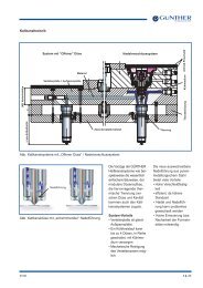
All <strong>GÜNTHER</strong> valve-gate systems offer a wide range of possibilities for meeting optical requirements at the gating.<br />
They prevent stringing on the product and make it possible to reduce the cycle time and keep shear stress low in the plastic being processed.<br />
Valve- gate technology is ideal for producing large shot volumes and wide gating point cross-sections.<br />
The innovative design of the contouring needle guide and the optimised valve-gate needle allow non-contact and low-wear gate closing.<br />
The PM needle guide made of metallurgical powder steel ensures economical and virtually wear-free operation. While closing, the needle is first<br />
centred through a tapered guide until it lowers precisely into the cylindrical guide.<br />
Another advantage is the separation of needle guide and material tube, which means that any necessary change of needle guide is a simple<br />
procedure. Special openings in the clamping plate allow the valve-gate needles to be adjusted individually from the outside.<br />
“ Electromagnet ME 10/UV75”, electric drive for valve-gate systems, chapter 5.<br />
• for electric injection moulding machine<br />
• absolute clean room compatible<br />
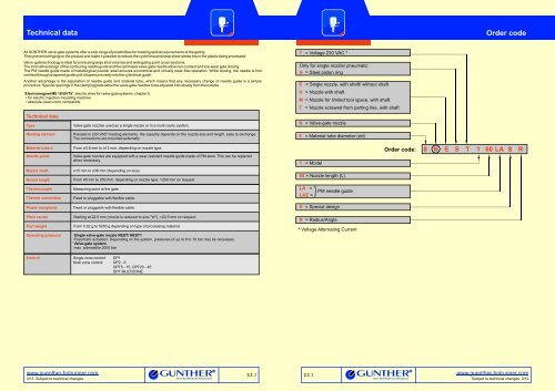
Technical data<br />
Type Valve-gate nozzles used as a single nozzle or in a multi cavity system.<br />
Heating element Pressed-in 230 VAC* heating elements, the capacity depends on the nozzle size and length, easy to exchange.<br />
The connections are mounted externally.<br />
T = Voltage 230 VAC *<br />
Only for single nozzle/ pneumatic<br />
S = Steel piston ring<br />
E = Single nozzle, with shaft/ without shaft<br />
H = Nozzle with shaft<br />
M = Nozzle for limited tool space, with shaft<br />
T = Nozzle screwed from parting line, with shaft<br />
N = Valve-gate nozzle<br />
8 = Material tube diameter (Ød)<br />
Material tube-Ø<br />
Needle guide<br />
From Ø3.8 mm to Ø12 mm, depending on nozzle type.<br />
Valve-gate nozzles are equipped with a wear-resistant needle guide made of PM steel. This can be replaced<br />
when necessary.<br />
1 = Model<br />
Order code:<br />
8 N E S T 1 60 LA S R<br />
Nozzle shaft<br />
Nozzle length<br />
Ø15 mm to Ø38 mm (depending on size)<br />
From 40 mm to 250 mm, depending on nozzle type. >250 mm on request.<br />
60 = Nozzle length (L)<br />
Thermocouple<br />
Thermo connection<br />
Measuring point at the gate.<br />
Fixed or pluggable with flexible cable.<br />
LA =<br />
LAZ =<br />
PM needle guide<br />
Power receptacle<br />
Pitch center<br />
Part weight<br />
Operating pressure<br />
Fixed or pluggable with flexible cable.<br />
Starting at 22.5 mm (nozzle is reduced to size "W"),
Notes<br />
PM needle guide<br />
1 Heat expansion gap “K”<br />
The "K" dimension required for the heat expansion must be ensured<br />
by grinding the titanium ring (5 mm)! The heat expansion<br />
gap is calculated by determining the difference between the<br />
nozzle (position of the titanium ring in the head of the nozzle)<br />
and the height of the mould (position of the centring ring)<br />
when assembled.<br />
* T specifies the difference between the processing temperature<br />
and the mould temperature!<br />
Nozzle type NEST, NEST1<br />
Typ<br />
5,<br />
6, 8<br />
10, 12<br />
T(°C)* 100 150 200 250 300 350<br />
K (mm)<br />
K (mm)<br />
0.09<br />
0.11<br />
0.16<br />
0.19<br />
0.23<br />
0.26<br />
0.29<br />
0.33<br />
The “K” dimensions allow for 0.03 mm pretensioning!<br />
2<br />
3<br />
4<br />
5<br />
6<br />
Recess for the M5 screws of the nozzle head.<br />
If you have any questions please call our technical<br />
consulting at +49 (0) 6451 - 50 08 0.<br />
0.36<br />
0.41<br />
0.42<br />
0.48<br />
Power and thermo connection may be bent only once in this area.<br />
Minimum bending radius R8.<br />
The cable channel layout is determined by the pitch center and<br />
location.<br />
Measurement L +0.02 refers to the gate diameter.<br />
If the valve gate nozzle is fitted with the nominal length, the<br />
needle projects 0.2 mm into the part.<br />
Please note<br />
1. Positive sealing<br />
There is no positive sealing between the nozzles and the<br />
manifold when the hot runner system is cold. The system is<br />
sealed when the operating temperature is reached.<br />
2. <strong>Hot</strong> runner nozzle<br />
a. In case of limited installation dimensions, the nozzle<br />
head can be flattened to fit the dimension W when using<br />
the following nozzle types: NHT, NHT1, NMT, NTT2<br />
b. The nozzle type NMT, NTT2 hot runner nozzles are not<br />
screwed to the manifold .<br />
c. Disassemble the nozzle out of the cavity plate please<br />
use a nozzle extractor tool, chapter 8.<br />
3. Gate diameter<br />
The gate diameter D depends on the material used, part weight<br />
and nozzle diameter.<br />
4. Pitch center<br />
a. The minimum pitch center depends on the nozzle type.<br />
If the nozzle heads are close together than a support piece<br />
is not necessary.<br />
b. Please note the dimensions of the needle actuation.<br />
5. High temperature application<br />
Please call our technical consulting if you have questions about<br />
high temperature applications >320°C.<br />
6. Dimensions and tolerances<br />
Dimensions and tolerances given refer to the mold.<br />
7. Heat expansion gap "K”<br />
Please see chapter 4 (yellow page) for the heat expansion gap<br />
dimension “K”.<br />
8. Maximum tightening torque<br />
Threads<br />
M4<br />
M5<br />
M6<br />
M8<br />
M10<br />
M12<br />
M16<br />
Materialtube<br />
Ø<br />
mm<br />
Property class<br />
10.9 12.9<br />
3.8 Nm<br />
8.0 Nm<br />
13.0 Nm<br />
34.0 Nm<br />
68.0 Nm<br />
117.0 Nm<br />
285.0 Nm<br />
9. Technical information, chapter 1.4.<br />
4.6 Nm<br />
9.5 Nm<br />
16.0 Nm<br />
39.6 Nm<br />
80.0 Nm<br />
137.0 Nm<br />
333.0 Nm<br />
10. NEST, NEST1 Single valve-gate nozzle<br />
Caution! When assembling / dismantling the needle holder (A/F 10),<br />
care must be taken not todeform the steel piston rings. Use the flat<br />
of the piston!<br />
It is essential to put the metal o-ring back in after replacing the<br />
disk package.<br />
The piston and/or the steel piston rings must be greased again<br />
before assembly (<strong>GÜNTHER</strong> recommends Klüber paste<br />
UH 196-402 [NSF registered]).<br />
It is essential to ensure that the steel piston rings have been<br />
inserted correctly. The rings have a marking (XXX) on the faces surface,<br />
indicating the side that must point towards the pressurised side.<br />
When maintenance work is being done, the screws<br />
(property class 12.9) which attach the upper section must be in a<br />
heated state (300°C) when they are tightened.<br />
5, 6NEST....<br />
8NEST1...<br />
10, 12NEST1...<br />
Inlet/ outlet pipes for activating the needle<br />
It is preferable to use channels with diameters of 6 mm and a<br />
minimum length of 200 mm. The inlet and outlet lines must be<br />
placed in the temperature-controlled mould plate in order to<br />
prevent the compressed air overheating.The temperature should<br />
be between 40°C and 70°C.<br />
If the mould temperatures exceed the thermal stress capability of<br />
the pneumatic valves, a separately cooled manifold must be<br />
installed. The mechanics of the needle drive and the valve-gate<br />
nozzle are absolutely capable of withstanding high temperatures.<br />
11. Gate diameter Ø<br />
Valveneedle<br />
Ø mm<br />
2<br />
3<br />
3<br />
3<br />
5<br />
4<br />
5<br />
6<br />
8<br />
10, 12<br />
M5<br />
M6<br />
M8<br />
Gate diameter Ø mm<br />
9.5 Nm<br />
16.0 Nm<br />
39.6 Nm<br />
Tolerance zone for the nozzle seat in the cavity plate:<br />
H6<br />
Dimensions Ø to 3 =<br />
> 3....6 =<br />
H7<br />
Dimensions Ø > 10...18 =<br />
0.8 1.0 1.2 1.4 1.6 2.0 2.5 3.0 3.5 4.0<br />
Gate diameter-Ø: standard, delivery time upon request<br />
> 18...30 =<br />
+0.006<br />
0<br />
+0.008<br />
0<br />
+0.018<br />
0<br />
+0.021<br />
0<br />
> 30...50 = +0.025 0<br />
Order code<br />
Following parts must be ordered separately:.<br />
1. CMLK thermoplug<br />
for nozzle type NEST, NHT<br />
2. CMT power receptacle<br />
for nozzle type NEST, NHT<br />
Please note:<br />
The mechanic of the single nozzle type NEST/ NEST1 is equipped<br />
with fixed power- and thermo couple connection.<br />
PM needle guide LA Cut-out in the gate area<br />
7<br />
PM needle guide LA<br />
of metallurgical powder steel<br />
The needle guide can be easily chan-ged as required. By<br />
replacing the PM needle guide and the needle, the injec-tion gate<br />
diameter can be enlarged or reduced without any re-machining of<br />
the mold nest. The precision of the needle guide allows a virtually<br />
wear-free seal and a clean gate without burrs.<br />
Advantages:<br />
• High longevity due to extreme wear resistance<br />
• Insert exchangeabal<br />
• Short cycle times<br />
• Excellent and vestige-free gating quality<br />
• Very good cosmetic quality<br />
• No need to replace or re-machine mold inserts<br />
• Low shear stress<br />
For more technical information please see the respective nozzle<br />
type page.<br />
PM-needle guide<br />
Valve needle<br />
3. The needle is not a component of the valve-gate nozzle because<br />
the needle length depends on the nozzle length, actuation<br />
mechanism and manifold assembly.<br />
4. Slide extractor tool to exchange the needle guide, chapter 8.<br />
5. Steel piston ring, to exchange, chapter 8.<br />
Nozzle size 4-6 (material tube-Ø mm)<br />
R0.4<br />
sharp edged<br />
deburred<br />
Nozzle size<br />
4<br />
5<br />
6<br />
Nozzle size 8-12 (material tube-Ø mm)<br />
R<br />
R1<br />
sharp edged<br />
deburred<br />
Nozzle size<br />
8<br />
10<br />
12<br />
R<br />
Angle (Wi)<br />
ØS5 -0.1<br />
ØS5<br />
4.1<br />
5.0<br />
5.0<br />
0.4<br />
0.8<br />
0.8<br />
0.4<br />
0.4<br />
60°<br />
Ø3.5<br />
R1<br />
0.4<br />
1.2<br />
1.2<br />
A<br />
H7<br />
ØS6 -0.1<br />
90°<br />
ØS5 -0.1<br />
60°<br />
H7<br />
ØS7<br />
A<br />
ØS6 -0.1<br />
ØS6<br />
3.9<br />
4.6<br />
4.6<br />
ØS5<br />
7.4<br />
10.8<br />
10.8<br />
ØS6<br />
7.0<br />
10.4<br />
10.4<br />
Ø0.01 A<br />
t6<br />
1.85<br />
1.25<br />
1.25<br />
Ø0.01 A<br />
ØS7<br />
5.0<br />
6.5<br />
6.5<br />
0.01 A<br />
t5<br />
t6<br />
1 +0.1<br />
t6<br />
t5 ±0.05<br />
1.20<br />
1.32<br />
1.32<br />
0.4<br />
3.2 -0.02<br />
Angle (Wi)<br />
60°<br />
90°<br />
90°<br />
0.01 A<br />
0.4<br />
t6<br />
t7 -0.02<br />
2.2<br />
2.6<br />
2.6<br />
5<br />
5<br />
t7<br />
4.2<br />
4.8<br />
4.8<br />
2.3. 4<br />
www.guenther-hotrunner.com<br />
Subject to technical changes 3/13
PM needle guide<br />
PM needle guide LA<br />
Special design with titanium ring<br />
Cut-out in the gate area<br />
Nozzle size 4-6 (material tube-Ø mm)<br />
Ø0.01 A<br />
R0.4<br />
R0.4<br />
R0.2<br />
sharp edged<br />
deburred<br />
0.4<br />
H7<br />
ØS5<br />
0.4<br />
60°<br />
Ø3.5<br />
H7<br />
A<br />
30°<br />
Ø0.01 A<br />
1 +0.1<br />
0.01 A<br />
1.4 -0.02 t5<br />
3.2<br />
5<br />
7<br />
PM needle guide LA<br />
Special design with titanium ring<br />
The thermal insulation of the PM needle<br />
guide provided by a titanium ring allows<br />
a much wider range of applications of<br />
the valve gate nozzle with the following<br />
plastics<br />
•<br />
•<br />
•<br />
•<br />
Polyamides (PA4.6, PA6.6, HTN)<br />
Thermoplastic polyesters<br />
(PBT, PET)<br />
Liquid crystalline polymer (LCP)<br />
Polyetheretherketone (PEEK)<br />
Nozzle size<br />
4<br />
5<br />
6<br />
ØS5<br />
6.5<br />
7.0<br />
7.0<br />
t5<br />
1.4<br />
1.5<br />
1.5<br />
Nozzle size 8-12 (material tube-Ø mm)<br />
Ø0.01 A<br />
H7<br />
ØS5<br />
A<br />
30°<br />
0.01 A<br />
5<br />
R0.4<br />
R0.2<br />
R<br />
sharp edged<br />
deburred<br />
0.4<br />
0.4<br />
60°<br />
H7<br />
ØS6<br />
Ø0.01 A<br />
t5 ±0.05<br />
t6 -0.02 t7<br />
t8<br />
Nozzle size<br />
R<br />
ØS5<br />
ØS6<br />
t5<br />
t6<br />
t7<br />
t8<br />
8<br />
0.4<br />
10.0<br />
5.0<br />
1.20<br />
2.4<br />
1.5<br />
4.2<br />
10<br />
1.2<br />
14.5<br />
6.5<br />
1.32<br />
2.2<br />
2.3<br />
4.8<br />
12<br />
1.2<br />
14.5<br />
6.5<br />
1.32<br />
2.2<br />
2.3<br />
4.8<br />
Titanium ring<br />
PM needle guide<br />
Valve needle<br />
www.guenther-hotrunner.com<br />
11/12 Subject to technical changes<br />
2.3. 6
PM needle guide<br />
PM needle guide LAZ<br />
Cut-out in the gate area<br />
Nozzle size 4-6 (material tube-Ø mm)<br />
R0.4<br />
sharp edged<br />
deburred<br />
Nozzle size<br />
4<br />
5<br />
6<br />
8<br />
Angle (Wi)<br />
ØS5 -0.1<br />
0.4<br />
ØS5<br />
4.1<br />
5.0<br />
5.0<br />
7.4<br />
70°<br />
H6<br />
ØS7<br />
ØS6 -0.1<br />
A<br />
ØS6<br />
3.9<br />
4.6<br />
4.6<br />
7.0<br />
t5<br />
Ø0.01 A<br />
0.58<br />
0.58<br />
0.58<br />
0.63<br />
t7<br />
0.01 A<br />
+0.05<br />
t5<br />
± 0.05<br />
t6<br />
3.2<br />
3.2<br />
3.2<br />
4.2<br />
0.4<br />
t7 -0.02<br />
Angle (Wi)<br />
60°<br />
90°<br />
90°<br />
90°<br />
5<br />
7<br />
PM needle guide LAZ<br />
of pulvermetalurgical steel<br />
The needle guide can be easily changed<br />
as required. By replacing the PM<br />
needle guide and the needle, the injection<br />
gate diameter can be enlarged or<br />
reduced without any re-machining of<br />
the mold nest. The precision of the<br />
needle guide allows a virtually wearfree<br />
seal and a clean gate without<br />
burrs.<br />
The LAZ needle guide is tapered in<br />
form with a smaller contact area,<br />
which reduces the imprint made.<br />
This version is suitable for molding<br />
parts with a small wall thickness, or<br />
for parts which contours do not<br />
permit any larger imprint.<br />
Advantages:<br />
• High longevity due to extreme wear<br />
resistance<br />
• Insert exchangeable<br />
• Short cycle times<br />
• Excellent and vestige-free gating<br />
quality<br />
• Very good cosmetic quality<br />
• No need to replace or re-machine<br />
mold inserts<br />
• Low shear stress<br />
Assembly<br />
dimensions<br />
ØD<br />
0.8<br />
Nozzle<br />
size<br />
ØS7<br />
2.2<br />
4<br />
t6<br />
1.41<br />
5<br />
t6<br />
0.91<br />
6 8<br />
t6 t6<br />
0.91 -<br />
1.0<br />
2.4<br />
1.55<br />
1.05<br />
1.05<br />
-<br />
1.2<br />
2.6<br />
1.70<br />
1.20<br />
1.20<br />
-<br />
1.4<br />
2.8<br />
1.84<br />
1.34<br />
1.34<br />
-<br />
1.6<br />
3.0<br />
-<br />
-<br />
1.48<br />
-<br />
2.0<br />
3.5<br />
-<br />
-<br />
-<br />
1.07<br />
2.5<br />
4.0<br />
-<br />
-<br />
-<br />
1.43<br />
PM needle guide<br />
Valve needle<br />
2.3. 7<br />
www.guenther-hotrunner.com<br />
Subject to technical changes 11/12
Nozzle/ material compatibility<br />
Nozzle type<br />
NEST<br />
Page 2.3. 20<br />
NEST1<br />
Page 2.3. 20/22<br />
NHT<br />
Page 2.3. 60<br />
NHT1<br />
Page 2.3. 65<br />
5<br />
6<br />
8<br />
10<br />
12<br />
4<br />
5<br />
6<br />
8<br />
10<br />
12<br />
ABS<br />
LCP 2)<br />
PA 4.6<br />
PA 6<br />
PA 6.6<br />
3) 4)<br />
PA 6.6+V0+GF<br />
PA 6.6+V0+ W<br />
1)<br />
PA 11<br />
PA 12<br />
PA 6+V0+W 1)<br />
PBT<br />
PC<br />
PE<br />
PBT+V0<br />
PBT+V0+W 1)<br />
PEEK 2)<br />
PEI<br />
PES<br />
PET<br />
PMMA<br />
PP<br />
PPA<br />
PPO<br />
PPS 2)<br />
PPSU<br />
PS<br />
PSU<br />
POM<br />
4)<br />
Homo<br />
POM Copolimer<br />
PVC, soft<br />
PVC, hard<br />
SAN<br />
TPE 5)<br />
TPU<br />
Nozzle type<br />
E<br />
H<br />
M<br />
T<br />
= Single-nozzle with shaft<br />
= screwed to the manifold with shaft<br />
= for limited tool space, not screwed to the<br />
manifold with shaft<br />
= screwed from parting line, with shaft<br />
The nozzle size depends on the shot weight, taking<br />
into consideration pressure drop and dwell time. To<br />
confirm material/nozzle compatibility please contact<br />
our technical consulting department.<br />
1) Heatstabilized, please contact us<br />
2) Only nozzles for high temperature applications, no<br />
standard version<br />
3) Up to a shot weight of approx. 5 g per nozzle a titanium<br />
ring should be inserted under the nozzle head (nozzle<br />
type NMT).<br />
4) For applications of the nozzle types NHT1/ NMT with<br />
long cycle times the use of a titanium ring under the<br />
nozzle head is recommended.<br />
5) For the processing of TPE in multiple cavity tools it is<br />
advisable to use valve-gate systems.<br />
NMT<br />
Page 2.3. 100<br />
4<br />
5<br />
6<br />
3) 3) 3) 3) 3) 3)<br />
3) 3) 3) 3)<br />
3) 3) 3) 3) 3)<br />
3) 3) 3)<br />
3) 3) 3) 3) 3)<br />
PBT<br />
PA 12<br />
PA 11<br />
NTT2<br />
Page 2.3. 140<br />
4<br />
5<br />
6<br />
PMMA<br />
PET<br />
PES<br />
PEI<br />
PEEK 2)<br />
PE<br />
PC<br />
PBT+V0+W 1)<br />
PBT+V0<br />
TPU<br />
TPE<br />
SAN<br />
PVC, hard<br />
PVC, soft<br />
PSU<br />
PS<br />
PPSU<br />
PPS 2)<br />
PPO<br />
PPA<br />
PP<br />
PA 6<br />
PA 4.6<br />
LCP 2)<br />
PA 6.6<br />
4)<br />
PA 6+V0+W 1)<br />
Suitable Limited suitability On request<br />
ABS<br />
PA 6.6+V0+<br />
1)<br />
PA 6.6+V0+GF<br />
POM Copolimer<br />
POM<br />
4)<br />
Homo<br />
W<br />
www.guenther-hotrunner.com<br />
11/12 Subject to technical changes<br />
2.3. 8
Valve-gate nozzle type<br />
type<br />
5-6NEST,<br />
pneumatic<br />
8NEST1,<br />
pneumatic<br />
Nadelverschlussdüsen, Einzeldüse mit Schaft verschraubt von Trennebene, mit Schaft.<br />
Assembly<br />
141.13<br />
5<br />
136.03<br />
5 +0.1<br />
0.5x45°<br />
B<br />
0.25x45°<br />
Detail X<br />
136.03<br />
2.5 - 3 mm revolving<br />
1<br />
K<br />
A<br />
Detail X<br />
ØS1 H7<br />
View B-B: Bore hole/thread in the cavity plate<br />
12.3 H7 11 tief<br />
20°<br />
20°<br />
10.74 ±0.01<br />
29.51 ±0.,01<br />
Insulation ring<br />
Clamping<br />
plate<br />
Frame<br />
plate<br />
Cavity plate<br />
Ø56<br />
B<br />
A<br />
View A-A: Frame plate<br />
7<br />
ca. 102<br />
R2<br />
90°<br />
+0.4<br />
ØS2<br />
R2<br />
6.3<br />
ØS3 +0.1<br />
ØS H7<br />
5)<br />
Power- and thermoconnections<br />
shown<br />
rotated 90°et<br />
Confer with technical consulting<br />
6.3<br />
A<br />
1.6<br />
0.4<br />
45°<br />
min. 10<br />
V -0.2<br />
Ø0.02 A<br />
min. t1<br />
5<br />
A<br />
28<br />
80<br />
Order code<br />
Example: Single valve-gate nozzle<br />
6NEST50/LA-0.8/ R 40<br />
6 = Material tube Ø d 6 mm,<br />
NEST = Single valve-gate nozzle,<br />
with steel piston ring,<br />
50 = Lenght mm,<br />
LA = PM needle guide,<br />
0.8 = Gate Ø mm,<br />
R 40 = Nozzle head radius<br />
Please indicate material type, article, part<br />
weight, kind of gating, gate-Ø and machine<br />
nozzle radius/angle in your order.<br />
Notes<br />
Actuation medium: pneumatic<br />
Pneumatic tube, inside diameter min. 6 mm<br />
Pneumatic valve size min. 750 L/min.<br />
Power and thermo conntections shown<br />
rotated 90°<br />
1)<br />
2)<br />
3)<br />
4)<br />
1<br />
Fixed power connection<br />
incl. 2 m flexible cable<br />
Fixed thermo connection<br />
incl. 2 mflexible cabel<br />
Power receptacle CMT<br />
Thermoplug CMLK<br />
The position of the nozzle can be secured by<br />
the flute in the housing (anti-twist protection).<br />
If you have any questions regarding the<br />
altered piping for the driving medium, we<br />
recommend that you consult the technical<br />
consulting.<br />
Recommendation: for better cooling, the air<br />
supply lines provided in the mould should be<br />
as long as possible.<br />
For an optimum thermal separation between<br />
the nozzle and the mould, use the (blue)<br />
insulation ring.<br />
The needles are adjusted precisely by means<br />
of shims (0.1 mm) in the piston.<br />
The nozzle is actuated with 2 control circuits.<br />
t1<br />
R/W<br />
5)<br />
The dimension can be extended as<br />
required to achieve a larger fitting<br />
diameter ØS H7.<br />
The construction of the machine nozzle<br />
determines which type of connecting<br />
piece should be use<br />
straight, R (radius) R 13, (R ½”), R 15,<br />
R 20 (R ¾”) R 40<br />
W (angle) 90°, 120<br />
Screw centring with at least 6x M10<br />
(12.9) (DIN EN ISO 4762) screws, with<br />
due consideration to lift forces.<br />
.... as well as further technical notes<br />
on the “yellow page”.<br />
Dimensions<br />
Nozzle type<br />
5NEST<br />
6NEST<br />
8NEST1<br />
Nozzle (mm)<br />
Ød<br />
4.8<br />
6.0<br />
7.5<br />
ØS<br />
22<br />
26<br />
26<br />
23<br />
27<br />
27<br />
Assembly (mm)<br />
ØS1 ØS2 ØS3 t1 V<br />
22.5<br />
26.5<br />
26.5<br />
10.6<br />
10.6<br />
12.6<br />
32<br />
35<br />
35<br />
Detail Radius R/<br />
Angle W<br />
9.0<br />
11.0<br />
10.9<br />
L 141.13<br />
38<br />
6<br />
Single valve-gate nozzle<br />
with steel piston ring, with shaft<br />
Valve<br />
needle<br />
7<br />
Part edge<br />
4<br />
137.13<br />
Delivery time<br />
Nozzle type<br />
5NEST<br />
6NEST<br />
8NEST1<br />
Ø82 +1<br />
Ø39<br />
Detail Radius R/ Angle W<br />
R<br />
Ød<br />
ØS1<br />
ØS<br />
Ø6.5<br />
4<br />
Nozzle length L (mm)<br />
W<br />
40 50 60 80 100 120 150 200 250<br />
= short delivery time, = delivery time upon request<br />
3<br />
1)<br />
2)<br />
Nozzle size 5 + 6NEST<br />
4) 3)<br />
Nozzle size 8NEST1<br />
2) 1)<br />
Ø6.5<br />
N E ST/...1 HK-S I<br />
NHT HK-S II<br />
NTT2 NMT NHT1<br />
www.guenther-hotrunner.com<br />
11/12 Subject to technical changes<br />
2.3. 20
Valve-gate nozzle type 10-12NEST1,<br />
pneumatic<br />
Nadelverschlussdüsen, verschraubt von Trennebene, mit Schaft.<br />
Assembly<br />
154.88<br />
149.78<br />
Detail X<br />
Clampin<br />
plate<br />
A<br />
3)<br />
Order code<br />
Example: Single valve-gate nozzle<br />
10NEST1-100/LA-3.0/ R 40<br />
10 = Material tube Ø d 10 mm,<br />
NEST1 = Single valve-gate nozzle,<br />
with steel piston ring,<br />
100 = Lenght mm,<br />
LA = PM needle guide,<br />
3.0 = Gate Ø mm,<br />
R 40 = Nozzle head radius<br />
Please indicate material type, article, part<br />
weight, kind of gating, gate-Ø and machine<br />
nozzle radius/angle in your order.<br />
Notes<br />
Detail Radius R/<br />
Angle W<br />
154.88<br />
Single valve-gate nozzle<br />
with steel piston ring, with shaft<br />
Ø100.5 +1<br />
Ø39<br />
Ød<br />
3<br />
1)<br />
N E ST/...1 HK-S I<br />
5<br />
0.5x45°<br />
10 +0.1<br />
B<br />
0.25x45° 0,25x45°<br />
A<br />
ØS1 H7<br />
View B-B: Bore hole/thread in the cavity plate<br />
12.3 H7 11 depth<br />
15°<br />
15°<br />
8.22 ±0.01<br />
Detail X<br />
149.78<br />
2.5 - 3 mm revolving<br />
1<br />
K<br />
Insulation ring<br />
30.67 ±0.01<br />
Frame<br />
plate<br />
Cavity plate<br />
Ø56<br />
B<br />
View A-A: Frame plate<br />
7<br />
R2<br />
ca. 122<br />
+0.4<br />
ØS2<br />
R0.4<br />
90°<br />
A<br />
20 +0.1<br />
ØS<br />
H7<br />
Power- and thermoconnections<br />
shown<br />
rotated 90°et<br />
Confer with technical consulting<br />
6.3<br />
6.3<br />
1.6<br />
1.6<br />
min. 10<br />
45°<br />
V -0.2<br />
min. t1<br />
5<br />
Ø0.02 A<br />
A<br />
17 11<br />
80<br />
Actuation medium: pneumatic<br />
Pneumatic tube, inside diameter min. 6 mm<br />
Pneumatic valve size min. 750 L/min.<br />
Power and thermo conntections shown<br />
rotated 90°<br />
1)<br />
2)<br />
1<br />
Dimensions<br />
Nozzle type<br />
NEST1<br />
10<br />
12<br />
Fixed power connection<br />
incl. 2 m flexible cable<br />
Fixed thrmo connection<br />
incl. 2 m flexible cable<br />
The position of the nozzle can be secured by<br />
the flute in the housing (anti-twist protection).<br />
If you have any questions regarding the<br />
altered piping for the driving medium, we<br />
recommend that you consult the technical<br />
consulting.<br />
Recommendation: for better cooling, the air<br />
supply lines provided in the mould should be<br />
as long as possible.<br />
For an optimum thermal separation between<br />
the nozzle and the mould, use the (blue)<br />
insulation ring.<br />
The needles are adjusted precisely by means<br />
of shims (0.1 mm) in the piston.<br />
The nozzle is actuated with 2 control circuits.<br />
t1<br />
R/W<br />
3)<br />
The dimension can be extended as<br />
required to achieve a larger fitting<br />
diameter ØS H7.<br />
The construction of the machine nozzle<br />
determines which type of connecting<br />
piece should be use<br />
straight, R (radius) R 13, (R ½”), R 15,<br />
R 20 (R ¾”) R 40<br />
W (angle) 90°, 120<br />
Screw centring with at least 6x M10<br />
(12.9) (DIN EN ISO 4762) screws,<br />
with due consideration to lift forces.<br />
.... as well as further technical notes<br />
on the “yellow page”.<br />
Nozzle (mm)<br />
Ød<br />
10<br />
12<br />
ØS<br />
32<br />
38<br />
33<br />
39<br />
Assembly (mm)<br />
ØS1 ØS2 t1<br />
32.5<br />
38.5<br />
38<br />
39<br />
V<br />
13.9<br />
15.3<br />
L<br />
6<br />
38<br />
Part edge<br />
Delivery time<br />
Nozzle type<br />
NEST1<br />
10<br />
12<br />
ØS1<br />
ØS<br />
Detail Radius R/ Angle W<br />
4<br />
150.88<br />
R<br />
7<br />
3<br />
Valve needle<br />
8<br />
8<br />
167 ±15<br />
7<br />
Fixed thermo<br />
connection incl.<br />
2 m flexible cable<br />
Ø10<br />
4<br />
8<br />
W<br />
Nozzle lengt L (mm)<br />
9<br />
10<br />
40 50 60 80 100 120 150 200 250<br />
2)<br />
Ø10<br />
12<br />
Fixed power<br />
connection incl.<br />
2 m flexible cable<br />
NHT HK-S II<br />
NTT2 NMT NHT1<br />
= short delivery time, = delivery time upon request<br />
www.guenther-hotrunner.com<br />
11/12 Subject to technical changes<br />
2.3. 22