Günther Heisskanaltechnik & Heisskanalsysteme, Hot runner
Günther Heisskanaltechnik & Heisskanalsysteme, Hot runner
Günther Heisskanaltechnik & Heisskanalsysteme, Hot runner

Create successful ePaper yourself
Turn your PDF publications into a flip-book with our unique Google optimized e-Paper software.
10/99 DPK 1.09 1-1
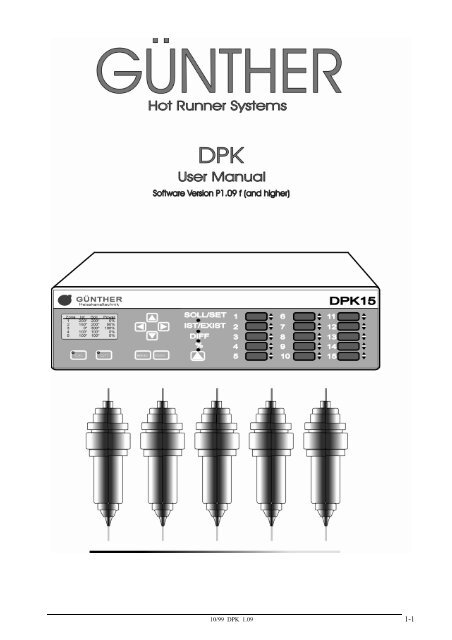
User Manual <strong>Hot</strong> Runner Systems DPK<br />
Table of Contents:<br />
GÜNTHER<br />
<strong>Hot</strong> Runner Systems<br />
Page<br />
1 GENERAL______________________________________________________________________ 1-4<br />
2 DISPLAY AND OPERATING CONTROLS__________________________________________ 2-6<br />
2.1 CONTROL PANEL ________________________________________________________2-6<br />
2.2 PARALLEL DISPLAY ______________________________________________________2-7<br />
3 OPERATING INSTRUCTIONS____________________________________________________ 3-8<br />
3.1 TURNING ON____________________________________________________________3-8<br />
3.2 MULTI-CHANNEL MODE __________________________________________________3-8<br />
3.3 SINGLE CHANNEL MODE __________________________________________________3-9<br />
3.4 OPERATING MODE ______________________________________________________3-10<br />
3.4.1 Changing Set Values _________________________________________________________________ 3-10<br />
3.4.2 Switching <strong>Hot</strong> Runners On and Off_____________________________________________________ 3-11<br />
3.4.3 Changing the Operating Mode „Thermocouple/Percentage“ ________________________________ 3-12<br />
3.4.4 Temperature Lowering / Rising ________________________________________________________ 3-13<br />
3.5 MENU MODE __________________________________________________________3-14<br />
3.5.1 Set All Channels ____________________________________________________________________ 3-16<br />
3.5.2 Temperature Program _______________________________________________________________ 3-16<br />
3.5.3 Temperature Lowering/Rising _________________________________________________________ 3-17<br />
3.5.4 Serial Interface _____________________________________________________________________ 3-17<br />
3.5.5 Power Monitor______________________________________________________________________ 3-17<br />
3.5.6 Turn On Time ______________________________________________________________________ 3-18<br />
3.5.7 Configuration_______________________________________________________________________ 3-18<br />
3.5.8 Heater 5V/24V ______________________________________________________________________ 3-18<br />
3.5.9 Language __________________________________________________________________________ 3-18<br />
3.5.10 Service ___________________________________________________________________________ 3-18<br />
3.6 CONFIGURATION MENU__________________________________________________3-19<br />
3.6.1 Softstart ___________________________________________________________________________ 3-19<br />
3.6.2 Load Defaults_______________________________________________________________________ 3-20<br />
3.6.3 Calibration_________________________________________________________________________ 3-21<br />
3.6.4 PID - Parameter ____________________________________________________________________ 3-21<br />
3.6.5 Switching °C / F_____________________________________________________________________ 3-22<br />
3.6.6 Temperature Window________________________________________________________________ 3-22<br />
4 OTHER FUNCTIONS ___________________________________________________________ 4-23<br />
4.1 READY TO START MOLDING ______________________________________________4-23<br />
4.2 ERROR MESSAGES ______________________________________________________4-23<br />
4.3 STARTING RAMP _______________________________________________________4-27<br />
5 SERIAL INTERFACE ___________________________________________________________ 5-28<br />
5.1 GENERAL INFORMATION _________________________________________________5-28<br />
5.2 TROUBLE SHOOTING ____________________________________________________5-29<br />
1-2<br />
10/99 DPK 1.09
Table of Contents:<br />
Page<br />
6 INSTALLATION AND START-UP ________________________________________________ 6-30<br />
6.1 INSTALLATION _________________________________________________________6-30<br />
6.1.1 Location ___________________________________________________________________________ 6-30<br />
6.1.2 Electrical Connections _______________________________________________________________ 6-30<br />
6.1.3 Additional Interfaces_________________________________________________________________ 6-32<br />
6.2 INITIAL START-UP ______________________________________________________6-35<br />
6.2.1 Testing Thermocouple Connections_____________________________________________________ 6-35<br />
6.2.2 Testing Heater Disconnections _________________________________________________________ 6-35<br />
6.2.3 Testing Thermocouple and Load Crosswiring ____________________________________________ 6-35<br />
6.2.4 Aditional Information: _______________________________________________________________ 6-36<br />
6.3 INSTALLING NEW SOFTWARE-EPROM´S ____________________________________6-36<br />
7 APPENDIX ____________________________________________________________________ 7-37<br />
7.1 APPENDIX A – CONNECTIONS TO THE DPK __________________________________7-37<br />
7.2 APPENDIX B - FUSES ____________________________________________________7-39<br />
7.3 APPENDIX C – STAR-/DELTA OPPERATION __________________________________7-41<br />
7.4 APPENDIX D – TECHNICAL DATA __________________________________________7-42<br />
7.5 APPENDIX E - SERVICE FORM _____________________________________________7-45<br />
7.6 APPENDIX F – SCHEMATIC _______________________________________________7-46<br />
7.7 APPENDIX G – POSITION SCHEMATIC_______________________________________7-47<br />
7.8 APPENDIX H - ADDRESSES________________________________________________7-48<br />
7.9 APPENDIX I – EG DECLARATION OF CONFORMITY ____________________________7-51<br />
10/99 DPK 1.09 1-3
User Manual <strong>Hot</strong> Runner Systems DPK<br />
Warranty Condtions:<br />
1. Installation and implementation must be carried out by an electrician!<br />
GÜNTHER<br />
<strong>Hot</strong> Runner Systems<br />
2. Please refer to chapter 6 - Installation and Inplementation of the DPK user<br />
manual prior to the installion of the device!<br />
3. Before connecting the device to the main power supply, check the main<br />
voltage and the type of net (star or delta)!<br />
1 General<br />
The hot <strong>runner</strong> system DPK has been built and tested according to DIN 57411 part 1 and<br />
VDE 0411 part 1 (Germany). It has left the factory in perfect condition. In order to keep your<br />
product fully operational and to guarantee safe operation, please read this instruction manual<br />
carefully and follow all hints. Before switching on, it is important to check that the local<br />
voltage is identical to that allowed by the unit. The plug may only be plugged into to an<br />
earthed socket. Any disconnection of the earth cable (e.g. an extension of the cable without<br />
earth connected) can cause hazardous conditions to the unit.<br />
Hint:<br />
Disconnect mains before opening unit. Refer to a qualified technician for servicing.<br />
The DPK unit is an optimized hot <strong>runner</strong> control unit, it is more efficient and reduces costs.<br />
Advantages for the user:<br />
• Available in 5, 10, or 15 hot <strong>runner</strong> versions according to the user’s requirements.<br />
• The DPK automatically recognizes low voltage nozzles and 230V hot <strong>runner</strong> elements and<br />
sets its control parameters accordingly.<br />
• Only one unit is required for mixed operation .<br />
• PID controller with variable parameters, fast heating of 5V and 24V low voltage nozzles,<br />
careful heating of 230V hot <strong>runner</strong> elements.<br />
• Control operation is possible at all times even in the event of thermocouple failure.<br />
• Existing power units from the 160 series can continue to be used as the DPK control unit is<br />
compatible with all existing GÜNTHER power units.<br />
• Because of the module construction, system upgrades are possible.<br />
The DPK is reliable and safe, due to continuous checking and monitoring functions.<br />
Advantages for the user:<br />
• Continuous self-monitoring function.<br />
• Protects low voltage nozzles from current overload.<br />
• Identifies thermocouple failures, heat circuit disconnections and short circuits.<br />
• Turns off the power supply in case of a malfunction and signals the alarm via a potential<br />
free contact.<br />
• Parameters and programs are saved in an EPROM and are therefore not lost in the case of a<br />
power supply failure.<br />
1-4<br />
10/99 DPK 1.09
The DPK is designed for easy use, this makes installation and tool change simple.<br />
Advantages for the user:<br />
• The DPK is especially designed for simple and easy operation.<br />
• The multi-function keypad has an easy to use layout and because of its dust and water<br />
proof key pad, it withstands tough environments.<br />
• The simple operator entry levels prevents wrong operation.<br />
• All hot <strong>runner</strong>s are simultaneously displayed and for each hot <strong>runner</strong> the set and actual<br />
values.<br />
• The control parameters are adjustable according to the application.<br />
• The implemented diagnostic tests the complete system, including tools, nozzles,<br />
distributors and the hot <strong>runner</strong> system for malfunction.<br />
• Incorrectly connected circuits are located before start of operation.<br />
• Low installation cost due to combined thermal and power connections.<br />
The DPK has numerous special functions for optimal system utilization<br />
Advantages for the user:<br />
• Power output surveillance is possible during operation.<br />
• Decrease and increase temperature for all control points by simply pressing a key.<br />
• Reading of the effective current at low voltage.<br />
• Several set value programs simplify material or tool change.<br />
• If desired, a serial interface is available as connection to the injection molding machines.<br />
10/99 DPK 1.09 1-5
User Manual <strong>Hot</strong> Runner Systems DPK<br />
2 Display and Operating Controls<br />
GÜNTHER<br />
<strong>Hot</strong> Runner Systems<br />
The display and operating controls of the DPK are located on the operation control panel and the<br />
parallel display. Great emphasis has been placed upon ease of use and a good layout.<br />
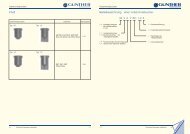
2.1 Control Panel<br />
GÜNTHER<br />
<strong>Heisskanaltechnik</strong><br />
Ch Exist Set Power<br />
1 200° 200° 0%<br />
2 150° 200° 50%<br />
3 0° 300° 100%<br />
4 100° 100° 0%<br />
5 100° 100° 0%<br />
F<br />
G<br />
°C/F↓<br />
°C/F↑<br />
ENTER<br />
H<br />
A B E C D<br />
Fig. 2-1 control panel DPK<br />
Function Keys<br />
A Key „°C/F↓“ > lowering temperature all zones<br />
B Key „°C/F↑“ > raising temperature all zones<br />
C Key „MENU“ > show menu<br />
E – H Keys „!“, „"“, „#“, „$“ > changing & adjusting set values and parameters,<br />
cancel function<br />
D Key „ENTER“ > ´ENTER KEY´ to confirm inputs,<br />
to quit program levels<br />
Hint:<br />
For further details concerning keys and their functions see chapter 3.3 Operation.<br />
2-6<br />
10/99 DPK 1.09
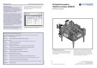
2.2 Parallel Display<br />
The parallel display is a 15-fold 3-digit seven segment display for set temperature, actual<br />
temperature, temperature difference or actual adjustable variables in ´%´. Three additional LEDs are<br />
located beside each indicator to display the status of the zone.<br />
If a channel is turned off, " --- " appears in the accompanying display. The percent control variable<br />
is displayed to channels which work in the setting mode.<br />
Fig. 2-1 parallel display DPK<br />
Between the operating controls and parallel display the “#“ key and 4 LED´s are placed. The key is<br />
used to display the set value, actual value, temperature difference or the display of current in „%“.<br />
The LEDs above the key shows the selected display type.<br />
The temperature state in addition is one by one displayed for every channel. If the green indicator<br />
shines behind the corresponding value, this channel has reached the programed temperature window<br />
(ready for molding). There is an over and under indicator also which is a red indicator for both<br />
conditions.<br />
10/99 DPK 1.09 2-7
User Manual <strong>Hot</strong> Runner Systems DPK<br />
3 Operating Instructions<br />
GÜNTHER<br />
<strong>Hot</strong> Runner Systems<br />
3.1 Turning On<br />
After the unit has been switched on the <strong>Günther</strong> logo, the program revision number and the serial<br />
Number will be shown on the display. Then the unit automatically performs a system check which<br />
includes the heating circuits, whether a low voltage or a 230 volt load is connected. After the<br />
system check the DPK detects the load if it is a low voltage or 230 V .The Display will show a table<br />
of all loads. If faults are detected on the system or the loads (nozzles, distributor or cables) the fault<br />
is displayed and the loads are switched off. At the same time the parallel display shows TST (Test)<br />
and then the detected voltage of the load. If a load turned of in reasen of a fault, or if it is not<br />
connected, the parallel Display will be shown „---“.<br />
3.2 Multi-Channel Mode<br />
After the adjusting of the loads has been performed, the controller is in the multi-channel mode. In<br />
this mode every five channels are display for a short time interval.<br />
GÜNTHER<br />
<strong>Heisskanaltechnik</strong><br />
Ch Exist Set Power<br />
1 200° 200° 0%<br />
2 150° 200° 50%<br />
3 0° 300° 100%<br />
4 100° 100° 0%<br />
5 100° 100° 0%<br />
°C/F↓<br />
°C/F↑<br />
Fig. 3-1 Multi-Channel Mode<br />
The set value and the current value in degrees celsius or degrees fahrenheit is displayed in this<br />
mode. The control value is also displayed in per cent (%) for 230V nozzles or in ampere (A) for<br />
24V or 5V nozzles.<br />
230V loads pass through a so-called softstart if the set temperature is higher than 105°C (221°F). If<br />
the softstart is active, all 230V loads are clamped to 105°C. This clamping ends if all loads have<br />
reached this temperature (see chapter 3.6.1 Softstart).<br />
Hint:<br />
At the apperance of any failure the multi-channel mode will be interupted and the failure will<br />
be visualized on the display. If several errors occur, then the channel whose error was<br />
recognized first is displayed. This is also valid if the display is switched from the menu mode<br />
to the multi-channel mode after the apperance of any failure.<br />
3-8<br />
10/99 DPK 1.09
3.3 Single Channel Mode<br />
To change from the multi-channel mode to the single-channel, mark a channel with the keys marked<br />
„#“ or „$“. By pressing the keys „"“ or „Enter“ the channel is entered in single-channel mode.<br />
The single-channel mode is now shown on the display. In this mode all data (rated value, actual<br />
value, load caracter, current, power consumption) of each channel will be shown.<br />
GÜNTHER<br />
<strong>Heisskanaltechnik</strong><br />
200 °C<br />
CH Act.<br />
1 Set<br />
°C<br />
200<br />
24V<br />
ON<br />
4 A<br />
°C/F↓<br />
°C/F↑<br />
Fig. 3-1 Single channel Mode<br />
At first, in the single-channel mode, the channel number is marked. By pressing the key „!“ the<br />
display mode returns to the multi-channel mode.<br />
Towards a cycle of 2 seconds the mark switched off, now it is possible by pressing the key „!“ to<br />
turn the display mode to the scan mode.<br />
The following sign indicates the scan mode.<br />
In this mode the zones with set and actual values will be displayed in the display, one by one.<br />
Runners wich are switched of will be skipped.<br />
The unit (%,A,°C,°F) for each zone number, will be displayed at the same time.<br />
The scan mode ca be cancelled by pressing any key and restarted by pressing the „!“ key after 2<br />
seconds when the mark of the channel nummber swiched off again.<br />
Hint:<br />
If a fault occurs, the scan mode will be terminated and channel number causing a fault will be<br />
shown on the display. If several faults occur at the same time, the zone where the first fault<br />
occured is displayed.<br />
10/99 DPK 1.09 3-9
User Manual <strong>Hot</strong> Runner Systems DPK<br />
3.4 Operating Mode<br />
GÜNTHER<br />
<strong>Hot</strong> Runner Systems<br />
3.4.1 Changing Set Values<br />
During the single-channel mode move the mark to the set value, by pressing the „"“ key. The<br />
desired set value is entered by pressing the key „#“ and „$“. The key function is dynamic i.e.<br />
the longer the key is pressed, the quicker the set point value changes.<br />
GÜNTHER<br />
<strong>Heisskanaltechnik</strong><br />
Ch Exist Set Power<br />
1 200° 200° 0%<br />
2 150° 200° 50%<br />
3 0° 300° 100%<br />
4 100° 100° 0%<br />
5 100° 100° 0%<br />
°C/F↓<br />
°C/F↑<br />
CH<br />
CH<br />
1<br />
24V<br />
Bild A<br />
1<br />
Act.<br />
Set<br />
ON<br />
Act.<br />
Set<br />
200 °C<br />
°C<br />
200<br />
Temp.<br />
200 °C<br />
°C<br />
200<br />
24V ON Temp.<br />
Bild B<br />
°C/F↑<br />
CH Act.<br />
200<br />
1 Set<br />
°C<br />
250<br />
24V<br />
Bild C<br />
ON<br />
4 A<br />
Fig. 3-1 Changing a Set Value<br />
The controller operation works independently from the entering of a value. It is therefore not<br />
necessary to return to the scan mode. Scan mode makes exact surveillance of critical regulation<br />
positions possible.<br />
Value limits: The temperatures are adjustable within a range from 0 to 500 °C<br />
(0 to 932 °F).<br />
The percentage control mode is adjustable from 0% to 100%.<br />
3-10<br />
10/99 DPK 1.09
3.4.2 Switching <strong>Hot</strong> Runners On and Off<br />
If a hot <strong>runner</strong> is unused, it is posible to switch it off.<br />
GÜNTHER<br />
<strong>Heisskanaltechnik</strong><br />
Ch Exist Set Power<br />
1 OFF<br />
2 150° 200° 50%<br />
3 0° 300° 100%<br />
4 100° 100° 0%<br />
5 100° 100° 0%<br />
°C/F↓<br />
°C/F↑<br />
CH<br />
CH<br />
1<br />
24V<br />
Bild A<br />
1<br />
Act<br />
Set<br />
OFF<br />
24V ON<br />
Bild B<br />
°C/F↓<br />
200<br />
Temp.<br />
°C<br />
°C<br />
Act.<br />
40 °C<br />
Set °C<br />
200<br />
Temp.<br />
°C/F↑<br />
200 °C<br />
CH Act.<br />
1 Set<br />
°C<br />
200<br />
24V<br />
Bild C<br />
ON<br />
4 A<br />
Fig. 3-1 Switching <strong>Hot</strong> Runners On and Off<br />
During the single-channel mode move the mark to the ON/OFF button by pressing the „"“ key.<br />
Now the setting may be changed by pressing the „#“ or „$“ key.<br />
Runners which are switched off will be displayed only in the multi-channel mode and are not<br />
checked for faults anymore.<br />
10/99 DPK 1.09 3-11
User Manual <strong>Hot</strong> Runner Systems DPK<br />
3.4.3 Changing the Operating Mode „Thermocouple/Percentage“<br />
GÜNTHER<br />
<strong>Hot</strong> Runner Systems<br />
In the event that a thermocouple fails to function, or for any other reason, the percentage control<br />
mode can be carried out to continue the control operation manually. The current will then be<br />
displayed in percent (%).<br />
Mark the menu item power or temp. in single-channel mode by pressing the „"“ key, choose<br />
between thermocouple or percentage by pressing the „#“ or „$“ key.<br />
GÜNTHER<br />
<strong>Heisskanaltechnik</strong><br />
Ch Exist Set Power<br />
1 200° 200° 0%<br />
2 150° 200° 50%<br />
3 0° 300° 100%<br />
4 100° 100° 0%<br />
5 100° 100° 0%<br />
°C/F↓<br />
°C/F↑<br />
CH<br />
CH<br />
1<br />
24V<br />
Bild A<br />
1<br />
24V<br />
Bild B<br />
Act.<br />
Set<br />
ON<br />
Act.<br />
Setl<br />
ON<br />
200 °C<br />
°C<br />
200<br />
Temp.<br />
200 °C<br />
°C<br />
200<br />
Temp.<br />
°C/F↑<br />
CH<br />
Percentage<br />
1 5 %<br />
24V<br />
Bild C<br />
ON<br />
Power<br />
Fig. 3-1 Changing the Operating Mode<br />
For low voltage-nozzles it will be: 100% approximately 125A (for 5V nozzles)<br />
100% approximately 25A (for 24V nozzles)<br />
3-12<br />
10/99 DPK 1.09
3.4.4 Temperature Lowering / Rising<br />
If production stops for a longer period of time, it is advisable to lower the set temperatures without<br />
turning the unit off.<br />
By pressing the key „°C/F↓“ lowering temperature is activated. The display shows in the multichannel<br />
mode at the left corner „t-lowering“, in the single-channel mode the following sign.<br />
An external activation of the temperature lowering is possible by connecting a closing contact at the<br />
rear side of the DPK. It is possible to connect a potential free contact to the unit with a cable which<br />
is available from GÜNTHER HOT RUNNER SYSTEMS (specially for relay output of injection<br />
molding machines).<br />
Additionally it is possible to increase the temperature for all <strong>runner</strong>s at the same time. By pressing<br />
the key „°C/F↑“ the temperature rise is activated. The display shows in the multi-channel mode at<br />
the left corner „t-boost“, in the single-channel mode the following sign.<br />
The temperature lowering mode is cancelled by pressing the key „°C/F↓“ once more. Now the old<br />
set values are valid. The lowering value may be adjusted by the menu temp. lowering (in °C/°F, 0 -<br />
255). The rise temperature mode is cancelled by pressing the key „°C/F↑“. The rising value may be<br />
adjusted by the menu temp. boost. If the lowering or rising is cancelled, the old set values are<br />
restored.<br />
10/99 DPK 1.09 3-13
User Manual <strong>Hot</strong> Runner Systems DPK<br />
3.5 Menu Mode<br />
GÜNTHER<br />
<strong>Hot</strong> Runner Systems<br />
By pressing the „menu“ key the menu mode is activated. The main menu will be shown on the<br />
display.<br />
GÜNTHER<br />
<strong>Heisskanaltechnik</strong><br />
main menu<br />
°C/F↓<br />
°C/F↑<br />
Fig. 3-1 Main Menu<br />
Use the „#“ und „$“ keys to select and the A or „ENTER“ key to confirm a menu item. If the<br />
operater does not makes modifications in the main or in a other menu the display mode will be<br />
changed after a time of 10 seconds and the display will show the single- or multi-channel mode.<br />
If a menu item is confirmed, the value may be changed by pressing the „#“ and „$“ keys. By<br />
pressing the „!“ oder „ENTER“ key you will return to the menu. If the „ENTER“ key is used the<br />
displayed value will be stored as a new set value. By using the „!“ key the value will not be stored<br />
(cancel function).<br />
The menu structure is on the next page.<br />
3-14<br />
10/99 DPK 1.09
Menustructure of the DPK<br />
Fig. 3-2 Menu structure of the DPK<br />
10/99 DPK 1.09 3-15
User Manual <strong>Hot</strong> Runner Systems DPK<br />
3.5.1 Set All Channels<br />
GÜNTHER<br />
<strong>Hot</strong> Runner Systems<br />
The menu „set all channels“ enables the operator to change the temperature, the controller output or<br />
to turn on or off all channel<br />
GÜNTHER<br />
<strong>Heisskanaltechnik</strong><br />
main menu<br />
set all temperature<br />
temp. :<br />
- ENTER -<br />
Bild A<br />
100 °C<br />
°C/F↓<br />
°C/F↑<br />
°C/F↓<br />
°C/F↑<br />
Fig. 3-1 Set All Channel<br />
3.5.2 Temperature Program<br />
A set value program is a preprogrammed series of set values and their corresponding operating<br />
methods which a user can change and enter into the system. They can be entered and activated<br />
solely by the menu „temp. program“.<br />
If the tools or the molding compounds are changed it is advisable to also change the program<br />
accordingly. There are 4 set values programs available. When the control unit is turned on, the last<br />
one of the previously used programs will be automatically reactivated.To reset all programs and all<br />
parameters select the menu item „default“.<br />
GÜNTHER<br />
<strong>Heisskanaltechnik</strong><br />
main menu<br />
temp. program<br />
1. power ON 50%<br />
2. power OFF 75%<br />
3. temp. ON 100°<br />
4. temp. OFF 200°<br />
default<br />
Bild A<br />
°C/F↓<br />
°C/F↑<br />
°C/F↓<br />
°C/F↑<br />
Fig. 3-1 Changing Temperature Program<br />
3-16<br />
10/99 DPK 1.09
3.5.3 Temperature Lowering/Rising<br />
By the two menus „temp. lowering“ and „temp. boost“ the operator could set the increase or<br />
decrease temperature. By using the „°C/F↓“ key the temperature drops about the value which<br />
adjusted in the menu „temp. lowering“. By using the „°C/F↑“ key the temperature rises about the<br />
value which adjusted in the menu „temp. boost“.<br />
3.5.4 Serial Interface<br />
The DPK is generally delivered with one serial interface „COM1“. This interface is a standard RS<br />
232 interface. The serial interface „COM1“ is only to connect a DPK to a personal computer or to<br />
comunicate with other DPK.<br />
An optional serial interface „COM2“ for injection molding machines is available. An add on Kit<br />
for delivered units is also available. With the interface „COM2“ it is possible to remote control and<br />
display the information of the DPK unit via the injection moulding machine. The interface enables<br />
easy quality control because of the possible production data acquisition.<br />
Because each injection moulding machine producer has ist own communication protocol, use the<br />
menu item „molding machine“ to select the protocol of the molding machine<br />
You can see which interface is needed by reading the user manual of the molding machine or<br />
contact <strong>Günther</strong> <strong>Hot</strong> Runner Systems for further information.<br />
In the menu are the items Arburg, Engel und Kraus Maffei (see Chapter 5 Interface).<br />
3.5.5 Power Monitor<br />
The menu power monitor will show the total power consumption and the current separated for each<br />
line at the moment.<br />
GÜNTHER<br />
<strong>Heisskanaltechnik</strong><br />
main menue<br />
power monitor<br />
L1 7.1 A 1560 W<br />
L2 5.6 A 1232 W<br />
L3 8.2 A 1804 W<br />
total power:<br />
EIN<br />
Bild A<br />
4596 W<br />
°C/F↓<br />
°C/F↑<br />
Fig. 3-1 Power Monitor<br />
10/99 DPK 1.09 3-17
User Manual <strong>Hot</strong> Runner Systems DPK<br />
3.5.6 Turn On Time<br />
GÜNTHER<br />
<strong>Hot</strong> Runner Systems<br />
The hours of operation are displayed in the menu turn on time. Every time when the DPK is<br />
switched on this time is incremented.<br />
3.5.7 Configuration<br />
By choosing the menu item configuration the configuration menu will be entered. You need a<br />
password to enter this menu. In the configuration menu the operater can change the language, the<br />
PID parameter or calibrate the DPK etc.<br />
For further information refer to Chapter 3.6 Configurationmenu.<br />
3.5.8 Heater 5V/24V<br />
In this menu item the type of the low voltage load (5V/24V) for all channels can be set. This means<br />
the DPK is able to work in a mixed mode with 230V and 5V nozzles or in a mixed mode with 230V<br />
and 24V nozzles. A mixed mode for 5V and 24V nozzles is not supported!<br />
3.5.9 Language<br />
In this menu item you are able to change the language for the display and the menu. The DPK<br />
supports three languages: german, english and french.<br />
3.5.10 Service<br />
This menu item is used by the manufacturer of the DPK for several setting. This menu has ist own<br />
password. The user must not and need not make any changes to this menu.<br />
3-18<br />
10/99 DPK 1.09
3.6 Configuration Menu<br />
By scrolling through the main menu, the configuration menu can be entered. A password is needed<br />
to enter this menu. In the configuration menu the operater can change the PID parameter or calibrate<br />
the DPK etc.<br />
The password for the configuratin menu is: 0099<br />
The entered password is only valid for 15 minutes or up to the moment where the DPK is turned off.<br />
For further changes to the configuration you need to enter it again.<br />
GÜNTHER<br />
<strong>Heisskanaltechnik</strong><br />
configuration<br />
°C/F↓<br />
°C/F↑<br />
Fig. 3-1 Configuration<br />
3.6.1 Softstart<br />
When 230V nozzles are used it is necessary to employ the softstart start-up procedure to dry out the<br />
moisture that has collected in the heating elements. In order to do this, in the first phase of the<br />
softstart (the set time) value of the menu softstart is increased from 0 to 50% . The ramp time<br />
should be selected in such a manner, that the DPK reaches the temperature of 105°C at the end of<br />
the ramp. If the temperature is less than 105°C at the end of the ramp, the DPK will increase the<br />
temperature to 105°C. After the DPK has reached the 105°C the second time controlled phase of the<br />
softstart (the holdtime) begins. The ramp and the hold time is adjustable by the menu softstart and<br />
could be changed in 2 seconds steps. The holdtime is used to adequately dry out the nozzle with a<br />
low thermic load. This start-up operation will begin automatically if it´s been activated in the<br />
softstart menu after the control unit or <strong>runner</strong> is switched on and also after a program change. The<br />
softstart start-up procedure is activated individually and automatically for each zone when the actual<br />
temperature of a 230V nozzle remains below 100°C, because the set value is programmed over<br />
100°C. The softstart is indicated in the single channel mode by the following sign.<br />
ramp time hold time<br />
In the multi channel mode by the text „softstart“ and the countdown in the left corner.<br />
After the end of the holdtime the unit will switch from softstart to normal operating mode. To<br />
prevent overheating of the molding material in the 5V nozzles during combined operations<br />
employing both 5V and 230V nozzles, the 5V nozzles are limited to temperatures not exceeding<br />
105°C during softstart. The temperature lowering is taken into consideration during softstarts, so<br />
that the DPK unit can begin to operate immediately with an instant temperature lowering.<br />
10/99 DPK 1.09 3-19
User Manual <strong>Hot</strong> Runner Systems DPK<br />
GÜNTHER<br />
<strong>Hot</strong> Runner Systems<br />
3.6.2 Load Defaults<br />
By selecting the menu item load defaults and affirming the questions with yes twice, the DPK loads<br />
up the parameters and values to the factory settings.<br />
Attention!<br />
All individual entered settings of the DPK (values and parameters) will be<br />
deleted!<br />
The following table shows the default settings:<br />
Set All Channels: 100°C<br />
(all set temperatures)<br />
Temperature Programs: 1. power ON 50%<br />
2. power OFF 75%<br />
3. temp. ON 100°C<br />
4. temp. OFF 200°C<br />
Softstart:<br />
ON<br />
over all time:<br />
hold time:<br />
ramp time:<br />
10min<br />
5min<br />
5min<br />
PID-Parameter: P-Value: 60<br />
(for all channels) I- Value: 60<br />
D- Value: 30<br />
Temperature Unit: °C<br />
Temperature Window: +/- 5°C<br />
Lowering Value: 50°C<br />
Rising Value: 50°C<br />
Language:<br />
Interface:<br />
Heater 5V/24V:<br />
German<br />
Arburg<br />
24V<br />
3-20<br />
10/99 DPK 1.09
3.6.3 Calibration<br />
The sophisticated and microcontroller seconded temperature module of the DPK could calibrate its<br />
self by using a calibrationjack.<br />
GÜNTHER<br />
<strong>Heisskanaltechnik</strong><br />
Bild A<br />
calibration<br />
configuration reading data ...<br />
calibrating offset ...<br />
calibrating gain ...<br />
writing data ...<br />
wait ...<br />
calibration<br />
reading data ...<br />
source missing !<br />
Bild C<br />
°C/F↓<br />
°C/F↑<br />
deviation<br />
min offset : 0 °c<br />
max offset : 2 °c<br />
avg offset : 1 °c<br />
min gain : 0 %<br />
max gain : 1,7 %<br />
avg gain : 0,6 %<br />
Bild B<br />
Fig. 3-1 Calibration<br />
The calibriation jack is available from GÜNTHER HOT RUNNER SYSTEMS, without the jack the<br />
error message of Fig. C will be shown on the display.<br />
3.6.4 PID - Parameter<br />
The operater can change the PID parameter using the menu item „pid-parameter“. So the operator is<br />
able to match the parameter to the controlled system. It is possible to match the paramters<br />
independently.<br />
10/99 DPK 1.09 3-21
User Manual <strong>Hot</strong> Runner Systems DPK<br />
3.6.5 Switching °C / F<br />
GÜNTHER<br />
<strong>Hot</strong> Runner Systems<br />
By choosing the menu item „switch °C/F“ it is possible to choose between degrees celsius or<br />
fahrenheit.<br />
GÜNTHER<br />
<strong>Heisskanaltechnik</strong><br />
configuration<br />
switch °c/f<br />
temperature in:<br />
celsius<br />
fahrenheit<br />
Bild A<br />
- ENTER -<br />
°C/F↓<br />
°C/F↑<br />
Fig. 3-1 Switching °C/°F<br />
3.6.6 Temperature Window<br />
The width of the windows for the value of the existing temperature can be changed in the menu item<br />
temperature window. Is the value of the temperature at the nozzle within this window, this will<br />
cause the lightning of the O.K. indicator in the parallel display. If all temperatures are in within the<br />
window, the ready to mold output will be set.<br />
3-22<br />
10/99 DPK 1.09
4 Other Functions<br />
4.1 Ready to Start Molding<br />
As soon as the adjusted <strong>runner</strong>s have reached the preset temperatures the OK LED is switched on<br />
and in the bottom line of the display appears the text „ready for molding“. Additionally a potential<br />
free relay contact is switch on. This relay contact is located on the rear side of the system and is<br />
marked with OK.<br />
The OK LED and the relay output will be switched off in case of:<br />
• a fault<br />
• lowering<br />
4.2 Error Messages<br />
In the event of a fault, the display will show the fault and the protection system will shut down the<br />
power. With this fault the relay contact is switched. By pressing the „ENTER“ key the faulty<br />
channel will be switched off and the other channels will be switched on.<br />
During the hot <strong>runner</strong> test all channels without a fault switched on and so it is not a mistake it is<br />
only a warning that the faulty channel is switched off.<br />
A channel which evoked a warning is switched in the off temperature mode when no load is<br />
detected and switched in the off percentage mode when no thermocouple is detected.<br />
The following faults are possible.<br />
GÜNTHER<br />
<strong>Heisskanaltechnik</strong><br />
Ch 1 error !<br />
thermocouple:<br />
break, floating<br />
or not connected<br />
Thermocouple Failure<br />
The thermocouple of the shown channel was not<br />
found. Please check the thermocouple and its` wires.<br />
- ENTER -<br />
°C/F↓<br />
°C/F↑<br />
Fig. 4-1 Thermocouple Failure<br />
10/99 DPK 1.09 4-23
User Manual <strong>Hot</strong> Runner Systems DPK<br />
GÜNTHER<br />
<strong>Heisskanaltechnik</strong><br />
Ch 1 error!<br />
thermocouple:<br />
GÜNTHER<br />
<strong>Hot</strong> Runner Systems<br />
Thermocouple Exchange<br />
The thermocouple of the shown channel is not<br />
connected right. The + and – connections are<br />
exchanged. Please change the direction of the<br />
connections.<br />
exchange<br />
- ENTER -<br />
°C/F↓<br />
°C/F↑<br />
Fig. 4-2 Thermocouple Exchange<br />
GÜNTHER<br />
<strong>Heisskanaltechnik</strong><br />
Ch 1 error !<br />
Thermocouple:<br />
Thermocouple Shortcut<br />
There is a short circuit at the thermocouple or its<br />
connections at the shown channel. Please check the<br />
thermocouple and its` wires.<br />
shortcut<br />
- ENTER -<br />
°C/F↓<br />
°C/F↑<br />
Fig. 4-3 Thermocouple Shortcut<br />
GÜNTHER<br />
<strong>Heisskanaltechnik</strong><br />
Ch 1 error!<br />
thermocouple:<br />
Over Temperature<br />
The thermocouple of the shown channel detects a<br />
temperature above 500°C. Please check this<br />
thermocouple and its` wires. You should also check<br />
the thermocouples for neighboring nozzles.<br />
over temperature<br />
- ENTER -<br />
°C/F↓<br />
°C/F↑<br />
Fig. 4-4 Over Temperature<br />
4-24<br />
10/99 DPK 1.09
GÜNTHER<br />
<strong>Heisskanaltechnik</strong><br />
Ch 1 error !<br />
thermocouple:<br />
check<br />
thermo-connector<br />
Check Thermo-connector<br />
The connector of the thermocouple at the shown<br />
channel is missing or is not fixed. Please check the<br />
connections.<br />
- ENTER -<br />
°C/F↓<br />
°C/F↑<br />
Fig. 4-5 Check Thermo-connector<br />
GÜNTHER<br />
<strong>Heisskanaltechnik</strong><br />
Ch 1 error!<br />
load:<br />
low power heater<br />
or not connected<br />
- ENTER -<br />
Load Interrupted<br />
The wires to the power module or to the nozzle of<br />
the shown channel are interrupted. Please check the<br />
load fuses and the wires.<br />
In normal operation the load interruption is only<br />
detected at a percetage value of 100%. This error<br />
message can occup at the adjustage. In this case,<br />
the power of the nozzle could be to small for this<br />
application.<br />
°C/F↓<br />
°C/F↑<br />
Fig. 4-6 Load Interrupted<br />
GÜNTHER<br />
<strong>Heisskanaltechnik</strong><br />
Load Connector Failure<br />
The load connector is lost or not fixed. Please<br />
check the connector.<br />
Ch 1 Error!<br />
load:<br />
check<br />
load-connector<br />
- ENTER -<br />
°C/F↓<br />
°C/F↑<br />
Fig. 4-7 Load Connector Failure<br />
10/99 DPK 1.09 4-25
User Manual <strong>Hot</strong> Runner Systems DPK<br />
GÜNTHER<br />
<strong>Heisskanaltechnik</strong><br />
warning !<br />
5/24v-load follows<br />
230v-load<br />
check wiring<br />
- ENTER -<br />
GÜNTHER<br />
<strong>Hot</strong> Runner Systems<br />
Plausibility Error<br />
The arrangement of the loads referring to the<br />
channel number is not the normal order. The low<br />
voltage nozzles should be connected to the low<br />
channel numbers. 230V nozzles should be to the<br />
higher channels after them.<br />
The parallel display shows the types of nozzles<br />
after the adjustment.<br />
If this order is chosen intentionally the opperation<br />
can go on after confirming this warning.<br />
°C/F↓<br />
°C/F↑<br />
Fig. 4-8 Plausibility Error<br />
GÜNTHER<br />
<strong>Heisskanaltechnik</strong><br />
°C/F↓<br />
error!<br />
triac short circuit<br />
on line x<br />
- ENTER -<br />
°C/F↑<br />
Damage of a Power Module<br />
Befoer the adjustment a damaged triac was found<br />
on one of the power modules. Every off the max<br />
three power modules is driven by one phase. So<br />
the damaged module can be found easy by<br />
disconntion the modules one by one.<br />
Please change the damaged module by an<br />
electrcian or contact <strong>Günther</strong> <strong>Hot</strong> Runner<br />
Systems.<br />
Please disconnect the line voltage before<br />
oppening the case! Pay attention to the safety<br />
instructions!<br />
Fig. 4-9 Damage of a Power Module<br />
4-26<br />
10/99 DPK 1.09
4.3 Starting Ramp<br />
In hot <strong>runner</strong> systems you will often find loads with different thermic time constants. If the time<br />
constants differ widely, then a fast nozzle reaches its set value earlier than the slow manifold. This<br />
physically based heat-up delay can generate plastic defects in the nozzle, because it reaches the set<br />
value much earlier then the other nozzles. The starting mechanism ensures an even set value based<br />
heat on all of the different nozzles. The individual nozzle will be decoupled from the leading<br />
mechanism if the slowest channel reached the temperature window.<br />
The starting ramp is indicated in the multi channel mode by a short text wich gives an information<br />
about the slowest channel and that the starting ramp is activated in the bottom line on the display<br />
and in the single channel mode by the following symbol.<br />
2<br />
The number behind the sign is the number of the slowest channel.<br />
10/99 DPK 1.09 4-27
User Manual <strong>Hot</strong> Runner Systems DPK<br />
5 Serial Interface<br />
GÜNTHER<br />
<strong>Hot</strong> Runner Systems<br />
5.1 General Information<br />
The DPK is equipped with one serial interface „COM1“ (see also chapter 3.5.4 Serial Interface).<br />
This is a standardized RS232 interface.<br />
An optional serial interface „COM2“ is available. An add on kit is also available. This second serial<br />
interface is used for a connection to a molding machine. With the interface „COM2“ it is possible to<br />
remote control and display the information of the DPK unit via the molding machine. It enables<br />
easy quality control caused of a product data aqusition. This time there a serveral types of serial<br />
interface available. Depending on the molding machine a RS232, a RS485 or a TTY interface is<br />
deliverable.<br />
Which interface is needed for your molding machine is described in the user manul of your<br />
machine. For further information please contact <strong>Günther</strong> <strong>Hot</strong> Runner Systems.<br />
Caused of several communication protocols for the different molding machines contact <strong>Günther</strong> <strong>Hot</strong><br />
Runner Systems for availability. (Please specify the type and manufacturer of your molding<br />
machine).<br />
Please refer the installation instructions for detailed information of installation.<br />
The DPK with an optional serial interface gets all data from the molding machine. Operation on the<br />
hot <strong>runner</strong> system is not necessary and for security reasons not possible. Parmeter and set<br />
temperature changes are impossible if the DPK is connected to a molding machine. This means<br />
especially the set values, the change all channels function, the temperature programs and the setting<br />
for temperature lowering and boost. A temperature lowering or rising is also not possible.<br />
Hint:<br />
If for example Parameters should be changed, the connection from the DPK to the molding<br />
machine must be opened. (Disconnect the cable to the molding machine after switching off the<br />
DPK or switch off the molding machine). This causes no more data to be sent to the DPK.<br />
Then the DPK notes that no interface operation is current. In this case the DPK enables any<br />
user opperations after a few seconds. The DPK then works as a stand alone unit. The<br />
parameters and setting from the molding machine are stored in the DPK. This increases easy<br />
diagnostics to the hot <strong>runner</strong> system.<br />
For the opperation hints for the interface of the different molding machines please refer your use<br />
manual.<br />
The following interface paramters are set if a protocol type is changed:<br />
Type Interface Type Parameters<br />
Arburg TTY 20mA 4800 Bit/s 8E1<br />
Engels TTY 20mA 4800 Bit/s 7E1<br />
Krauss-Maffei V24 / RS232 9600 Bit/s 7E2<br />
Mannesmann-Demag TTY 20mA 4800 Bit/s 8N1<br />
5-28<br />
10/99 DPK 1.09
5.2 Trouble Shooting<br />
Hint:<br />
For faults that are not associated with the interface connection, the DPK should be<br />
disconnected from the molding machine.<br />
There are several red and green LEDs inside the DPK. You can watch them after opening the case.<br />
The LEDs for the connection to the molding machine are located on the display circuit (front panel).<br />
The two other LEDs on the module LR 28 are for the internal communication between the<br />
operator/display panel and the regulator module.<br />
By flickering the LEDs indicate that a data flow is current.<br />
green / RXD<br />
red / TXD<br />
Input DPK<br />
Output DPK<br />
Flickering indicates: The DPK gets data from the molding machine.<br />
Flickering indicates: The DPK sends data.<br />
Hint:<br />
If the DPK detects any failure, the loads will be disconnected from the power line. This error<br />
state is displayed on the DPK. If the channel which caused this error is switched off, the error<br />
state is confirmed. After that the other channels are switched on again.<br />
Your can get further information in chapter 4.2 Error Messages and 6.2 Initial Start-Up.<br />
10/99 DPK 1.09 5-29
User Manual <strong>Hot</strong> Runner Systems DPK<br />
6 Installation and Start-Up<br />
GÜNTHER<br />
<strong>Hot</strong> Runner Systems<br />
6.1 Installation<br />
6.1.1 Location<br />
The absolute dimensions of the DPK are specified in appendix D. Pay attention to guarantee a<br />
sufficient air circulation behind the DPK regulator unit (heat sinks). Ensure sufficient air circulation<br />
at the bottom of the DPK is supplied by an installed fan. The system must be set up on a stable and<br />
level area. The DPK must be preserved from physical shock and vibration. For the maximum<br />
operating temperature please refer to appendix D. Please take care of the other operating conditions<br />
listed in apendix D. Protect the DPK from dust and dirt. When the device is assembled, for example<br />
in a service cabinet, a cable inlet of 120 x 90 mm should be provided.<br />
6.1.2 Electrical Connections<br />
The following electrical connections are required for installation:<br />
DPK:<br />
(Three phase CEE 32A plug) Phasedistribution:<br />
DPK 5 L1 Fuse 25A L2, L3 not connected<br />
DPK 10 L1, L2 Fuse 25A L3 not connected<br />
DPK 15 L1, L2, L3 Fuse 25A<br />
Hint:<br />
Please check mains voltage (star/delta) prior to installation. Star is the standard configuration<br />
of the delivered unit. Delta is possible if the voltage between two phases is not higher than<br />
200-250V. (Please refer to apendix C).<br />
Thermocouple Cables<br />
The thermocouple cable requires a 32 pin (2 x 16 pins) socket with a suitable housing. The cable<br />
assignment is listed in apendix A. Parts and preassembled, prewired thermocable systems will be<br />
supplied from Güther <strong>Hot</strong> Runner Systems.<br />
Power Cables<br />
The power cable requires a 40 pin connector plug with a suitable housing. Because of the large<br />
number of possible arrangements and the required special crimping tools, preassembled power<br />
cables manufactured by the GÜNTHER HOT RUNNER SYSTEMS should be used.<br />
In order to maintain a standard and for compatibility reasons the following procedures should be<br />
followed:<br />
If a combination of low voltage and 230V <strong>runner</strong>s is employed, the low voltage <strong>runner</strong>s should be<br />
connected in a sequential arrangement of increasing voltages, beginning with <strong>runner</strong> 1. After all low<br />
voltage <strong>runner</strong>s have been connected, the 230V <strong>runner</strong>s should then be connected to the system. For<br />
example in a 10 <strong>runner</strong> system, <strong>runner</strong>s 1 to 4 are low voltage types and <strong>runner</strong>s 5 to 10 are operated<br />
at 230V. The length of the power cable should not exceed 3 meters.<br />
6-30<br />
10/99 DPK 1.09
The following standard plug connections are avalible:<br />
Low Voltage:<br />
• 20 pin for power components type DL 4<br />
• 39 pin for power components type DL 6 and DL 8<br />
• 40 pin for power components type LS 4 - LS 12<br />
• 40 pin for power components type LR 4 - LR 12<br />
• For the 160/T12 respectively DL 12 one 20 pin and one 39 pin plug must be used<br />
230V:<br />
• 10 pin connector socket with cable for max. 5 <strong>runner</strong>s (AG 5)<br />
• 16 pin connector socket with cable for max. 8 <strong>runner</strong>s (AG 8)<br />
• 32 pin connector socket with cable for max. 15 <strong>runner</strong>s(AG 16)<br />
When ordering a power cable the following informations is required:<br />
• Number of low voltage <strong>runner</strong>s<br />
• Number of 230V <strong>runner</strong>s<br />
• Type of low voltage connection (such as 20 pin 39 pin or for DL4, for DL8 or DL12)<br />
• Type of 230V connections(10 pin, 16 pin or 32 pin) or (AG 5, AG 8, AG 16)<br />
Hint:<br />
To prevent connection errors between the temperature controller DPK and the power unit,<br />
the load connector of the DPK is mechanically coded. The power cables should be equipped<br />
with the same encoder system as the DPK.<br />
This applies only for units using a star net supply (see apendix C).<br />
You can also order cables for connecting several low power units to a DPK (e.g. connection<br />
for 2 x DL8 or 3 x DL4 etc.)<br />
Signal Inputs and Outputs of the DPK<br />
Output Fault (Def.)<br />
If a thermocouple or heating circuit failure is detected, it will be reported here.The output ´Defect´(=<br />
fault ) is a potential free normaly open contact for 230V~ (max. 1A) or a protected extra low<br />
potential as specified by VDE (VDE = ´union of german electrical engineering´). The contact must<br />
be fused externally. A corresponding plug with 2,5m cable can be ordered from the GÜNTHER<br />
HOT RUNNER SYSTEMS company.<br />
Output Ready to Start Molding (OK)<br />
As soon as the adjusted <strong>runner</strong>s have reached the preset temperatures the output „Ready to start<br />
molding operation“ is switched on. Additionally a potential free relay contact „OK“ for 230V~<br />
(max. 1A) is switched on. A corresponding plug with 2,5m cable can be ordered from the<br />
GÜNTHER HOT RUNNER SYSTEMS company.<br />
10/99 DPK 1.09 6-31
User Manual <strong>Hot</strong> Runner Systems DPK<br />
Input Lowering (Abs.)<br />
By using potential-free external contact, the DPK can be set to lowering.<br />
GÜNTHER<br />
<strong>Hot</strong> Runner Systems<br />
Hint:<br />
Attention: Never connect any voltage to this input!<br />
Serial Interface<br />
One serial interface (RS232) is included in every DPK.<br />
For a connection to a molding machine a second serial interface is required. Depending on the<br />
molding machine and its protocol a RS232, RS 485, RS422 or TTY- (current loop) interface is<br />
required. You can get this interface as an add on kit or from the manufacturer installed when<br />
ordering a new DPK. For further information please contact <strong>Günther</strong> <strong>Hot</strong> Runner Systems.<br />
6.1.3 Additional Interface<br />
The add on kit includes:<br />
• 1 interface module<br />
• 1 preassembled flatcable<br />
• 5 m interface cable 2 x 0.5 mm² shielded, assembled for connection to the molding<br />
machine Arburg, Engel or Krauss - Maffei (please note the type at your order).<br />
• 2 pcs. spacer bolts including nut<br />
Installation:<br />
Hint:<br />
Attention: Disconnect main power before opening system!<br />
• Remove the top cover by removing the four screws on the side of the unit.<br />
• Plug the interface into the 10 pin an 14 pin conectors on the front panel (LR27) (take<br />
caution of the right direction!).<br />
• Remover the cover panel at the rear side of the DPK.<br />
• Pull the pole connector with its flat cable through the opening of the unit and connect the<br />
D-SUB 9 pin connector by using the spacer bolts and nuts from the outside of the unit.<br />
• Plug the flat cable onto the interface module (take caution of the direction!).<br />
Attention:<br />
Check the polarity! Pin 1 of the PCD must correspond to pin 1 of the socket!<br />
• Check the right jumper settings<br />
• Close the top cover and fix it by using the srews.<br />
• Install the cable to the molding machine, connect it on both sides and fix the screws of<br />
the connectors.<br />
• Setup the right protocol type in the DPK.<br />
6-32<br />
10/99 DPK 1.09
5<br />
1<br />
9<br />
6<br />
DSUB 9<br />
female<br />
2 RXD<br />
3 TXD<br />
5 GND<br />
7 RTS<br />
8 CTS<br />
RS 232 Interface<br />
5<br />
1<br />
9<br />
6<br />
DSUB 9<br />
female<br />
1 1B (-)<br />
2 1Z (-)<br />
3 2B (-)<br />
4 2Z (-)<br />
6 1A (+)<br />
7 1Y (+)<br />
8 2A (+)<br />
9 2Y (+)<br />
RS 485 Interface<br />
5<br />
1<br />
9<br />
6<br />
1 RXD (-)<br />
4 TXD (-)<br />
6 RXD (+)<br />
9 TXD (+)<br />
TXD passive<br />
RXD passive<br />
DSUB 9<br />
female<br />
TTY Interface<br />
5<br />
1<br />
9<br />
6<br />
DSUB 9<br />
female<br />
1 CTS (-)<br />
2 RTS (-)<br />
3 RXD (-)<br />
4 TXD (-)<br />
6 CTS (+)<br />
7 RTS (+)<br />
8 RXD (+)<br />
9 TXD (+)<br />
RS 422 Interface<br />
Fig. 6-1 Interface Connections of the DPK<br />
5<br />
1<br />
9<br />
6<br />
1<br />
4<br />
6<br />
9<br />
+20mA<br />
3<br />
1<br />
DSUB 9<br />
male<br />
AMP DIN 5<br />
male<br />
Fig. 6-2 Wire Connection ARBURG<br />
5<br />
1<br />
9<br />
6<br />
1<br />
4<br />
6<br />
9<br />
+20mA<br />
3<br />
2<br />
5<br />
1<br />
9<br />
6<br />
DSUB 9<br />
male<br />
DSUB 9<br />
male<br />
Fig. 6-3 Wire Connection ARBURG<br />
10/99 DPK 1.09 6-33
User Manual <strong>Hot</strong> Runner Systems DPK<br />
GÜNTHER<br />
<strong>Hot</strong> Runner Systems<br />
Fig. 6-4 Wire Connection KRAUSS - MAFFEI<br />
5<br />
1<br />
9<br />
6<br />
1<br />
4<br />
6<br />
9<br />
+20mA<br />
4<br />
3<br />
2<br />
1<br />
DSUB 9<br />
male<br />
Weidmüller<br />
plug 4-pol.<br />
Fig. 6-5 Wire Connection ENGEL<br />
Hint:<br />
If an EPROM update is required at the same time of the interface installation, disconnect the<br />
molding machine from the DPK before switching on.<br />
At the order of an interface, please note the type of the interface!<br />
Technical Data (Optional Interface):<br />
Signal type<br />
Dataformat<br />
Baudrate<br />
Cable length<br />
Isolation<br />
RS232 level, TTY level (20mA current loop)<br />
optional: RS485 level, RS422 level,<br />
2 x asynchronous full duplex<br />
max. 19200 Baud<br />
max. 15m for RS232; max. 300m for TTY (cable cross section 0,4mm²);<br />
max. 1000m for RS422 and RS485<br />
5kV (Input / Output)<br />
6-34<br />
10/99 DPK 1.09
6.2 Initial Start-Up<br />
6.2.1 Testing Thermocouple Connections<br />
• Install the device refering to chapter 6.1 Installation. Disconnect the power connector!<br />
• Turn on the DPK. The DPK now shows the software version (e.g. P1.09) and begins to<br />
check the the hot <strong>runner</strong>s. Then the error message „check load-connector“ is displayed.<br />
• Change the parallel display to the set values by using the „ #“ key.<br />
• Make sure to set all channels to the regulating mode.<br />
• Switch the parallel display to the exist values.<br />
• Now all connected channels must show a temperature value. Otherwise the channels not<br />
working right have to be checked.<br />
• If the display only show maximum temperatures between 20°C and 40°C, then the blue<br />
and red cables of the thermocoples are expected to be exchanged.<br />
6.2.2 Testing Heater Disconnections<br />
• Switch off unused channels.<br />
• Set all channels to 0°C or 0% at disconnected load connector.<br />
• Connect the load connector.<br />
• After turning the device off and on there should be no „load circuit interupted“<br />
messages.<br />
• If there is any fault, the corresponding channel will be displayed.<br />
• For further testing the damaged channel should be switched off.<br />
6.2.3 Testing Thermocouple and Load Crosswiring<br />
• Set all channels to regulating mode and set a temperature value of 0°C.<br />
• Switch off unused channels to get no error messages from them.<br />
• Now no error messages should be displayed.<br />
• Set the parallel display to the existing values.<br />
• Set the first channel to 100°C and watch at the parallel display. The temperature of the<br />
corresponding channel should increase now. If the temperature of another channel<br />
increases faster, there is an error in the connection.<br />
• Set the channel to 0°C again.<br />
• Now test the next channel.<br />
10/99 DPK 1.09 6-35
User Manual <strong>Hot</strong> Runner Systems DPK<br />
6.2.4 Additional Information:<br />
GÜNTHER<br />
<strong>Hot</strong> Runner Systems<br />
Hint:<br />
When working with the 230V loads, switch off the DPK and disconnect it from the power<br />
source!<br />
Opposite of other regulating units for 230V, the DPK checks the loads at the power up precedure by<br />
using a current measurement. So a clear statement about a load disconnection could be given.<br />
For all channels the set value in ampere can be displayed.<br />
To check the heater current a clamp-ampmeter with true RMS measurement should be used. For<br />
low voltage nozzles a range of 0-150A is required. High voltage nozzles requires a range of 0-10A.<br />
If there are problems with the installation of the DPK, please contact our service department for<br />
help. Please use the service form in appendix E and send it to the next service department.<br />
6.3 Installing new EPROM updates<br />
Hint:<br />
Attention: Disconnect the mains voltage and take care that there is no voltage at the DPK<br />
before opening the device!<br />
Please follow the safety instructions!<br />
To install a software update disconnect the power and thermocouple connections from the DPK.<br />
Disconnect also the serial interface to a molding machine.<br />
Now remove the top cover of the DPK and get the EPROM out of the module LR28. When<br />
installing the new EPROM take care of the right direction and fit in socket of the circuit.<br />
After that get the EPROM out of the module LR27. When installing the new EPROM take also care<br />
of the right direction and fit in socket of the circuit.<br />
Following this step close the cover of the DPK.<br />
Attention!<br />
Do never exchage the EPROMs!<br />
After turning on the DPK again, the DPK performs an update and an adjustment.<br />
Now the DPK should work normally.<br />
The actual software version is displayed in the right lower edge of the display, when the DPK is<br />
turned on.<br />
6-36<br />
10/99 DPK 1.09
7 Appendix<br />
7.1 Appendix A – Connections to the DPK<br />
Fig. 7-1 Connections on the Rear Side of the DPK<br />
Ser.: Serial Interface, OK: Ready to Start Molding<br />
Def.: Fault,<br />
Abs.: Lowering external<br />
Channel: 1 2 3 4 5 6 7 8 9 10 11 12 13 14 15<br />
Metal / + / red 1 2 3 4 5 6 7 8 17 18 19 20 21 22 23<br />
Constantan / -/ blue 9 10 11 12 13 14 15 16 25 26 27 28 29 30 31<br />
Fig. 7-2 Thermocouple Connector ( 32 pin ) to the DPK<br />
Channel: 1 2 3 4 5 6 7 8 9 10 11 12 13 14 15<br />
External Conductor: A1 A2 A3 A4 B1 B2 B3 B4 C1 C2 C3 C4 D1 D2 D3<br />
Transducer: A7 A8 A9 A10 B7 B8 B9 B10 C7 C8 C9 C10 D4 D5 D6<br />
Transducer: D7 D8 D9 D10 D7 D8 D9 D10 D7 D8 D9 D10 D7 D8 D9<br />
Neutral Conductor: A5 A5 A6 A6 B5 B5 B6 B6 C5 C5 C6 C6 A6 B6 C6<br />
Fig. 7-3 Load Connector (40 pin) of the DPK15<br />
10/99 DPK 1.09 7-37
User Manual <strong>Hot</strong> Runner Systems DPK<br />
Channel: 1 2 3 4 5 6 7 8 9 10<br />
External Conductor: A1 A2 A3 A4 B1 B2 B3 B4 C1 C2<br />
Transducer: A7 A8 A9 A10 B7 B8 B9 B10 C7 C8<br />
Transducer: D7 D8 D9 D10 D7 D8 D9 D10 D7 D8<br />
Neutral Conductor: A5 A5 A6 A6 B5 B5 B6 B6 A6 B6<br />
Fig. 7-4 Load Connector (40 pin) of the DPK10<br />
GÜNTHER<br />
<strong>Hot</strong> Runner Systems<br />
Channel: 1 2 3 4 5<br />
External Conductor: A1 A2 A3 A4 B1<br />
Transducer: A7 A8 A9 A10 B7<br />
Transducer: D7 D8 D9 D10 D7<br />
Neutral Conductor: A5 A5 A6 A6 A6<br />
Fig. 7-5 Load Connector (40 pin) of the DPK5<br />
Hint:<br />
In star circuit the return cables A5, A6, B5, B6, C5 und C6 only connected to the neutral<br />
conductor. In the case of delta connection one does not mean an neutral conductor, but<br />
another external conductor (phase).<br />
The connection position for special appliance (revision S) is different from the shown.<br />
Fig. 7-6 Connection Example: Controller Runner A7 of the DPK10<br />
Hint:<br />
The load plug is different from the DPK15 corresponding to the appliance. Please take care of<br />
the corresponding table. (Fig. 7-3 to 7-5).<br />
7-38<br />
10/99 DPK 1.09
7.2 Appendix B - Fuses<br />
Fuse Location for the DPK:<br />
The up to 15 heating zones are fuse protected by super fast microfuses. At the DPK15 all of the load<br />
fuses are located on the back side of the controller.<br />
Note that you have to switch off the controller before changing any fuse!<br />
Hint:<br />
Use only original fuses with the corresponding specifications. One package of original reserve<br />
fuses has been enclosed with the DPK.<br />
Fig. 7-1 Position of the Load Fuses of the DPK<br />
The figure shows a part of the DPK’s back plate. The 15 fuses for all heating zones are placed on<br />
the left housing side. The three 16A fuse holders are mechanically different from the 10A holders.<br />
The fuse number correspond to the zone number.<br />
Hint:<br />
Please note, that the DPK can be delivered as 5, 10 or 15 channel system. The lettering of both<br />
upper 16A fuses have ambiguous meanings.<br />
The controller DPK5 contains four 10A-fuses for the zones 1 - 4 and one 16A-fuse for the zone 5.<br />
The controller DPK10 contains eight 10A-fuses for the zones 1 - 8 and two 16A-fuse for the zones 9<br />
and 10.<br />
The controller DPK15 contains 12 10A-fuses for the zones 1 - 12 and three 16A-fuse for the zones<br />
13,14 and 15.<br />
Additionally to the heating zone fuses, the DPK contains up to four internal controller fuses. The<br />
main controller fuse for the major electronics is placed on the main board LR28 and has a nominal<br />
value of 160mA (T). Each of the power moduls LR15 is has a separate 160mA controller fuse.<br />
10/99 DPK 1.09 7-39
User Manual <strong>Hot</strong> Runner Systems DPK<br />
Power Module „LR15“<br />
GÜNTHER<br />
<strong>Hot</strong> Runner Systems<br />
The phase control in the DPK is realized with the thyristor module LR 15.<br />
Depending on the model there are 1-3 modules inside of each DPK.<br />
Every module is driven by its own phase. Channel 1-5 by L1, channel 6-10 by L2 and channel 11-15<br />
by L3.<br />
On the LR 15 there are two jumpers for the channel setting. They have to be set like the figure<br />
shows.<br />
The DPK checks the thyristors of each power module at every adjustment. In case of an error the<br />
corresponding phase of the module is displayed with an error massage. The damaged module can be<br />
easy locted by measuring the phase.<br />
Attention!<br />
Attention: Disconnect the mains voltage and take care that there is no voltage at the DPK<br />
before opening the device!<br />
Please following these safety instructions!<br />
Fig. 7-2 Jumper Settings for the Power Module LR 15<br />
7-40<br />
10/99 DPK 1.09
7.3 Appendix C – Star-/Delta Opperation<br />
Hint:<br />
Attention!<br />
Disconnect the mains voltage and take care that there is no voltage at the DPK before opening<br />
the device!<br />
Please following these safety instructions!<br />
The unit DPK is prepared for a standard connection of a 400V star net supply. In case a 240V delta<br />
net supply is necessary (for example USA), this can be adapted by using four screwbridges.<br />
Disassemble the unit cover. Connect bridges as shown in the diagrams below.<br />
Fig. 7-1 Star- / Delta – Switch Over (U1=U2=U3=200V-250V !!!)<br />
Close the cover!<br />
Attention !!<br />
The voltages U1, U2 und U3 must be within a range of 200V-250V!<br />
If the unit is powered with other voltages the warranty expires and in some cases the unit can<br />
be damaged.<br />
When using a Delta-net supply the cable is not compatible for the different versions. That<br />
means that the DPK 5 should only be used with a cable intended for a five hot <strong>runner</strong> unit.<br />
The use of a cable designed for a 10 or 15 hot <strong>runner</strong> unit will lead to operations errors.<br />
10/99 DPK 1.09 7-41
User Manual <strong>Hot</strong> Runner Systems DPK<br />
7.4 Appendix D – Technical Data<br />
GÜNTHER<br />
<strong>Hot</strong> Runner Systems<br />
Connection Specifications:<br />
Terminal Voltages: 200-250 V AC per phase, 50 to 60Hz, typ. star connection<br />
Star Connection: 3-phase-supply with neutral, 200-250 V between phase<br />
and neutral<br />
Delta Connection: 3-phase-supply without neutral, 200-250 V between<br />
two phases<br />
Load Connection: 10A per channel (fuse 10A super fast= FF 10A) 1 <strong>runner</strong><br />
per phase 16A. (see max. current of phase !)<br />
phase load (5 channels per phase): max. 25A<br />
Maximum Power:<br />
DPK 5: phase L1: channel 1 - 4 = je 2,3 KW (10A)<br />
channel 5 = 3,6 KW (16A)<br />
max. overall load (CE): = 3,6 KW (16A)<br />
DPK 10: phase L1: channel 1 - 4 = je 2,3 KW (10A)<br />
channel 9 = 3,6 KW (16A)<br />
phase L2: channel 5 - 8 = je 2,3 KW (10A)<br />
channel 10 = 3,6 KW (16A)<br />
max. overall load (CE): = 7,2 KW (2x 16A)<br />
DPK 15: phase L1: channel 1 - 4 = je 2,3 KW (10A)<br />
channel 13 = 3,6 KW (16A)<br />
phase L2: channel 5 - 8 = je 2,3 KW (10A)<br />
channel 14 = 3,6 KW (16A)<br />
phase L3: channel 9 - 12 = je 2,3 KW (10A)<br />
channel 14 = 3,6 KW (16A)<br />
max. overall load (CE): = 10,8 KW (3x16A)<br />
(see also apendix A)<br />
5V / 120A per channel using our power units<br />
24V / 25A per channel using our power units<br />
Load Type:<br />
Thermocouple:<br />
Error Output:<br />
OK Output:<br />
Lowering Input:<br />
ohmic and inductive ohmic loads are allowed<br />
thermoelectric couple Typ L (FeCuNi) (electronic compensation)<br />
potential free contact, normaly open (max. 230V/1A, unfused)<br />
potential free contact, normaly open (max. 230V/1A, unfused)<br />
connect a potential free contact, normaly open<br />
7-42<br />
10/99 DPK 1.09
Net Cable:<br />
32A CEE plug (standard)<br />
Sockets: Load connector: 40 pin Amphenol<br />
Thermocouple connector: 32 pin Amphenol<br />
Fuses:<br />
Ser. Interface:<br />
Regulator:<br />
Load Matching:<br />
Output:<br />
Triac unit:<br />
- Microfuse FF 10A, 5 x 20mm, type Schurter SA, super fast for Triacs (4<br />
pcs. per module LR15)<br />
- Microfuse FF 16A, 6.3 x 32mm, type Schurter SA, (1 pcs. per module<br />
separated on the back side of the device)<br />
RS232, TTY, (RS422, RS485)<br />
At the moment protocols are availible for Arburg, Mannesmann, Krauss -<br />
Maffei and Engel. Further protocols are planed (e.g. SPI, EURO-<br />
MAP17, CAN BUS – please call us).<br />
PID, adjustable from the front<br />
parameters are programmable and can be locked<br />
automatic recognition of 230V and low voltage loads with<br />
automatic adjustment of the control parameters<br />
uniform automatic parameter match by means of phase control mechanism<br />
Control Range: 0 to 500°C / 0 to 932°F<br />
Set Range: 0 to 100%<br />
Softstart:<br />
3-phases<br />
1. adjustable ramp on 50% of the set value<br />
2. heat up to 105°C<br />
3. adjustable hold time on 105°C<br />
Starting Ramp:<br />
Equal heating of each nozzle depending on the slowest nozzle<br />
Lowering: adjustable 0 - 255°C / 0 - 255°F<br />
Boost: adjustable 0 - 255°C / 0 - 255°F<br />
Security Turn Off: adjustable 0 - 500°C / 0 - 500°F<br />
10/99 DPK 1.09 7-43
User Manual <strong>Hot</strong> Runner Systems DPK<br />
Other Details:<br />
GÜNTHER<br />
<strong>Hot</strong> Runner Systems<br />
Data Protection:<br />
Data recovery after power fail, data storage lifetime at least 10 years<br />
(without battery)<br />
Display: Operating section: LCD graphic display 40 x 71 mm<br />
Parallel display:<br />
seven segment LED display 8mm and LEDs<br />
Keyboard:<br />
Front panel with integrated mechanical keys and key foil<br />
Storage Temp.: 0 to 70°C<br />
Operating Temp.: 0 to 35°C<br />
Humidity: Storage: 30% - 80%, not condensing<br />
Operation: 40% - 70%, not condensing<br />
Protection Type: IP 20<br />
Dimensions:<br />
Weight:<br />
(W, H, D) 468mm x 142mm x 345mm<br />
13,0 Kg (28.6 lbs)<br />
Color: grey / blue (RAL 9018 / RAL 5015)<br />
7-44<br />
10/99 DPK 1.09
7.5 Appendix E - Service Form<br />
(Addresses: see Apendix H - Addresses)<br />
FAX<br />
To:<br />
From:<br />
Company:<br />
Company:<br />
Phone:<br />
Phone:<br />
FAX:<br />
FAX:<br />
City:<br />
City:<br />
Date:<br />
Date:<br />
Response partner:<br />
Please call back Ask for customer service Ask for repair Other<br />
Service-form for control units from the <strong>Günther</strong> <strong>Hot</strong> Runner Sytems company<br />
Type of unit:<br />
Serial number:<br />
Program version:<br />
Used connecting cable:<br />
Voltage:<br />
Net kind: Star Delta Other<br />
5V : Runners...<br />
24V : Runners...<br />
230V: Runners...<br />
If power units (5V / 24V) are used, are collective rails connected?<br />
Description of previous history (initial start up, prior operation, etc.)<br />
Problem description:<br />
Other:<br />
Notes:<br />
10/99 DPK 1.09 7-45
User Manual <strong>Hot</strong> Runner Systems DPK<br />
7.6 Appendix F – Schematic<br />
GÜNTHER<br />
<strong>Hot</strong> Runner Systems<br />
7-46<br />
10/99 DPK 1.09
7.7 Appendix G – Position Schematic<br />
10/99 DPK 1.09 7-47
User Manual <strong>Hot</strong> Runner Systems DPK<br />
GÜNTHER<br />
<strong>Hot</strong> Runner Systems<br />
7.8 Appendix H - Addresses<br />
Headquarter:<br />
GÜNTHER <strong>Heisskanaltechnik</strong> GmbH<br />
Industriegebiet Nord<br />
Sachsenberger Straße 1<br />
D-35066 Frankenberg (Eder)<br />
Germany<br />
Phone (++ 49) 64 51 50 08 0<br />
Fax (++ 49) 64 51 50 08 50<br />
Modem (++ 49) 64 51 50 08 61/62<br />
E-mail<br />
info@guenther-heisskanal.de<br />
Internet<br />
http://www.guenther-hot<strong>runner</strong>.com<br />
Germay<br />
Phone / Fax / E-mail<br />
GÜNTHER <strong>Heisskanaltechnik</strong> GmbH Phone (++ 49) 1 73 / 8 67 83 35<br />
Mr. Spork Fax (++ 49) 64 51 50 08 59<br />
Sachsenberger Str. 1<br />
E-mail spork@guenther-heisskanal.de<br />
D-35066 Frankenberg<br />
GÜNTHER <strong>Heisskanaltechnik</strong> GmbH Phone (++ 49) 1 72 / 9 41 12 26<br />
Mr. Stamm Fax (++ 49) 64 51 50 08 59<br />
Sachsenberger Str. 1<br />
E-mail stamm@guenther-heisskanal.de<br />
D-35066 Frankenberg<br />
WESCHU Phone (++ 49) 911 96 12 30 0<br />
Mr. Grajer Fax (++ 49) 911 96 12 30 50<br />
Edisonstr. 81<br />
E-mail thomas.grajer@weschu.de<br />
D-90431 Nürnberg<br />
Industrievertretungen Phone (++ 49) 36 84 88 68 0<br />
Mr. Römhild Fax (++ 49) 36 84 88 68 22<br />
Thomas-Mann-Str. 4<br />
E-mail roemhild-IV@gmx.de<br />
D-98597 Breitungen<br />
Verkaufsbüro Phone (++ 49) 74 54 66 81<br />
Mr. Renz Fax (++ 49) 74 54 16 67<br />
Kreuzweg 26<br />
E-mail k-h.renz@t-online.de<br />
D-72172 Sulz (Neckar)<br />
Verkaufsbüro Nord Phone (++ 49) 45 31 80 07 39<br />
Mr. Ilmer Fax (++ 49) 45 31 80 07 63<br />
Wolkenweher Weg 24<br />
E-mail w.h.ilmer@t-online.de<br />
D-23843 Bad Oldesloe<br />
7-48<br />
10/99 DPK 1.09
Worldwide<br />
Phone / Fax / E-mail<br />
Su-Pad Ltd. Phone (++ 972) 3 90 23 90 2<br />
Mr. Sadeh Fax (++ 972) 3 90 23 90 3<br />
2, Hamelacha Street E-mail supadltd@netvision.net.il<br />
New Industrial Zone<br />
IL-Rosh-Ha´ Ayn 48091<br />
Plastmaskiner A/S Phone (++ 47) 22 44 95 64<br />
Mr. Schröer Fax (++ 47) 22 55 11 06<br />
Frederik Stangs gate 2a<br />
E-mail plastkompaniet@os.telia.no<br />
N-0272 Oslo<br />
Dipl.-Ing. Petr Sochor Phone (++ 42 0) 1 84 72 39 66<br />
Ve Vilkách 1849 Fax (++ 42 0) 1 84 72 39 66<br />
CZ-347 01 Tachov<br />
E-mail guenther.trysky-sochor@iol.cz<br />
Basler Trade KFT Phone (++ 36) 12 39 05 17<br />
Mr. Zastrow Fax (++ 36) 12 39 05 17<br />
Postbox 25<br />
E-mail zastrow@westel900.net<br />
H-1581 Budapest<br />
Industrade Corporation Phone (++ 886) 2 22 99 03 16<br />
Room No. 202, No. 5 Fax (++ 886) 2 22 99 05 35<br />
Wu Chuan 1 Road<br />
E-mail industra@ms29.hinet.net<br />
Hsin Chuang. Taipei Hsien<br />
Taiwan. R. O. C.<br />
Eduardo Campos Madrigal Phone (++ 52) 55 66 47 32<br />
Grupo Zoica, S. A. de C. V. Fax (++ 52) 55 46 40 14<br />
Sadi Cornot No. 77<br />
E-mail zoica@df1.telmex.net.mx<br />
Col. San Rafael C. P. 06470<br />
Deleg. Cuauhtemoc Mexico D. F.<br />
GÜNTHER S.C. Phone (++ 48) 22 62 25 22 8<br />
Mr. Olszowski Fax (++ 48) 22 62 97 77 4<br />
ul. Poznanska 14 m 33<br />
PL-00-680 Warszawa<br />
HH Plastkombi aps Phone (++ 45) 48 79 98 88<br />
Mr. Hansen Fax (++ 45) 48 79 80 16<br />
Østergade 24 D<br />
E-mail mail@hh-plastkombi.dk<br />
DK-3200 Helsinge<br />
DUMIS Mlaka d.o.o. Phone (++ 386) 64 24 81 00<br />
Mr. Urana Fax (++ 386) 64 24 81 01<br />
Oretnekova pot 9 E-mail dumis@siol.net<br />
SL-4000 Kranj<br />
10/99 DPK 1.09 7-49
User Manual <strong>Hot</strong> Runner Systems DPK<br />
GÜNTHER<br />
<strong>Hot</strong> Runner Systems<br />
Worldwide<br />
Phone / Fax / E-mail<br />
Dipl.-Ing. H. <strong>Günther</strong> Ges.m.b.H. Phone (++ 43) 1 86 94 76 4<br />
Mr. Feik Fax (++ 43) 1 86 94 76 47<br />
Speichmühlgasse 1<br />
E-mail guenther@kabsi.at<br />
A-2380 Perchtoldsdorf<br />
Technisches Büro Bäcker Phone (++ 31) 75 68 18 00 0<br />
Mr. Bäcker Fax (++ 31) 75 68 18 00 1<br />
Pieter Lieftinckweg 20<br />
E-mail t.b.backer@wxs.nl<br />
NL-1505 HX Zaandam<br />
GÜNTHER France S.A. Phone (++ 33) 1 39 32 03 04<br />
Mr. Demicheli Fax (++ 33) 1 39 32 03 05<br />
6 rue Jules Verne E-mail m_demicheli@gunther-france.com<br />
F-95320 Saint Leu La Foret<br />
Millutensil SRL Phone (++ 39) 02 29 40 43 90<br />
Mrs. Just-Oselieri Fax (++ 39) 02 20 46 67 7<br />
Corso Buenos Aires 92<br />
E-mail millut@tin.it<br />
I-20124 Milano<br />
Trader Ingman Oy Phone (++ 358) 93 44 55 44<br />
Mr. Ingman Fax (++ 358) 93 43 40 52 0<br />
Strömsintie 23 A 1<br />
E-mail jukka@traderingman.fi<br />
FIN-00930 Helsinki<br />
GÜNTHER <strong>Hot</strong> Runner Systems Inc. Phone (++ 1) 84 72 15 78 74<br />
Mr. Vander Noot Fax (++ 1) 84 72 15 78 05<br />
725 Hastings Lane E-mail info@ghrsi.com<br />
USA-Mexico-Canada<br />
Buffalo Grove, Illinois 60089<br />
GÜNTHER U.K. Phone (++ 44) 14 74 87 97 74<br />
Mr. Heendeniya Fax (++ 44) 14 74 87 30 63<br />
52 Lambardes, New Ash Green E-mail info@gunther.co.uk<br />
GB-Longfield Kent DA3 8HU<br />
Brale Ltda. Phone (++ 55) 41 86 82 59 5<br />
Mr. Holdschmidt Fax (++ 55) 41 86 82 59 5<br />
Rua Joao de Barro, 52<br />
E-mail brale@brale.com.br<br />
BR-83326-470 Pinhais-PR<br />
Battenfeld Hong Kong Ltd. Phone (++ 852) 26 66 91 40<br />
Herr Pechtl Fax (++ 852) 26 65 25 26<br />
2 Fl. No.18 Dai Fat Street E-mail bathk@hk.super.net<br />
Tai Po Industrial Estate<br />
Hong Kong – N.T. Tai Po<br />
Center Plast Phone (++ 34) 93 47 37 71 3<br />
Mr. Gonzalez-Palacio Fax (++ 34) 93 49 90 43 8<br />
C/ San Gabriel, 17 L3 E-mail centerplast@airtel.net<br />
E- 08950 Esplugues de Llob.<br />
7-50<br />
10/99 DPK 1.09
Davidsmeyer & Paul GmbH<br />
7.9 Apendix I – EG Declaration of Conformity<br />
For the following below listed products:<br />
<strong>Günther</strong>-<strong>Hot</strong> Runner Controller DPK<br />
we hereby confirm, that above listed products comply to all important (*) safety<br />
requirements that have been declared by the Council of Assimilation of Legal<br />
Regulations by the EC membership countries concerning electromagnetical<br />
conformity.<br />
89/336/EWG EMV<br />
73/23/EWG Low Voltage Requirements<br />
To verify these products to electromagnetical conformity the following standards<br />
were referred to:<br />
EN 50081, Part 2<br />
EN 50082, Part 2<br />
The above mentioned products also comply to:<br />
DIN EN 61010, Teil 1/03.94.<br />
This declaration applies to all above listed products with the folowing production<br />
index:<br />
Production Index D and E<br />
The production index is the number behind the serial number on the identification<br />
label of the product. The identification label is located on the right side of the<br />
product.<br />
DAVIDSMEYER & PAUL GmbH Elektronik<br />
Humboldtstr.2-4<br />
D-50181 Bedburg<br />
Bedburg, 01.08.1999<br />
J. Marquardt<br />
(Managing Director)<br />
(*) Expressions recommended by "EMV-Rechtsvorschriften und ihre Anwendung in der Praxis", Franzis-Verlag, 1993<br />
10/99 DPK 1.09 7-51