AVR 1600 - Harman Kardon
AVR 1600 - Harman Kardon
AVR 1600 - Harman Kardon

You also want an ePaper? Increase the reach of your titles
YUMPU automatically turns print PDFs into web optimized ePapers that Google loves.
<strong>AVR</strong><strong>1600</strong><br />
harman/kardon<br />
T5CN5<br />
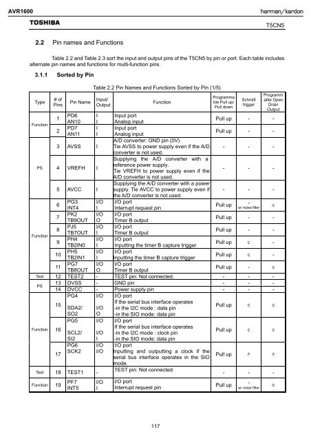
2.2 Pin names and Functions<br />
Table 2.2 and Table 2.3 sort the input and output pins of the T5CN5 by pin or port. Each table includes<br />
alternate pin names and functions for multi-function pins.<br />
3.1.1 Sorted by Pin<br />
Type<br />
Function<br />
Function<br />
Function<br />
# of<br />
Pins<br />
17<br />
Pin Name<br />
Table 2.2 Pin Names and Functions Sorted by Pin (1/5)<br />
Input/<br />
Output<br />
Function<br />
Programma<br />
ble Pull up/<br />
Pull down<br />
Schmitt<br />
trigger<br />
Programm<br />
able Open<br />
Drain<br />
Output<br />
filter¡<br />
¡<br />
¡<br />
1<br />
PD6 I Input port<br />
AN10 I Analog input<br />
Pull up - -<br />
2<br />
PD7 I Input port<br />
AN11 I Analog input<br />
Pull up - -<br />
A/D converter: GND pin (0V)<br />
3 AVSS I Tie AVSS to power supply even if the A/D - - -<br />
converter is not used.<br />
PS 4 VREFH I<br />
Supplying the A/D converter with a<br />
reference power supply.<br />
Tie VREFH to power supply even if the<br />
- - -<br />
A/D converter is not used.<br />
5 AVCC I<br />
Supplying the A/D converter with a power<br />
supply. Tie AVCC to power supply even if<br />
the A/D converter is not used.<br />
- - -<br />
6<br />
PG3 I/O I/O port<br />
Pull up<br />
INT4 I Interrupt request pin<br />
w/ noise<br />
7<br />
PK2 I/O I/O port<br />
TB9OUT O Timer B output<br />
Pull up - -<br />
8<br />
PJ5 I/O I/O port<br />
TB7OUT I Timer B output<br />
Pull up - -<br />
9<br />
PH4 I/O I/O port<br />
TB2IN0 I Inputting the timer B capture trigger<br />
Pull up -<br />
10<br />
PH5 I/O I/O port<br />
TB2IN1 I Inputting the timer B capture trigger<br />
Pull up -<br />
11<br />
PG7 I/O I/O port<br />
TB8OUT O Timer B output<br />
Pull up -<br />
Test 12 TEST2 - TEST pin: Not connected. - - -<br />
PS<br />
13 DVSS - GND pin - - -<br />
14 DVCC - Power supply pin - - -<br />
PG4 I/O I/O port<br />
15<br />
SDA2/ I/O<br />
If the serial bus interface operates<br />
-in the I2C mode : data pin<br />
Pull up<br />
SO2 O -in the SIO mode: data pin<br />
PG5 I/O I/O port<br />
16<br />
SCL2/ I/O<br />
If the serial bus interface operates<br />
-in the I2C mode : clock pin<br />
Pull up<br />
SI2 I -in the SIO mode: data pin<br />
PG6 I/O<br />
SCK2 I/O<br />
Test 18 TEST1 -<br />
Function 19<br />
PF7<br />
INT5<br />
I/O<br />
I<br />
I/O port<br />
Inputting and outputting a clock if the<br />
serial bus interface operates in the SIO<br />
mode.<br />
TEST pin: Not connected.<br />
I/O port<br />
Interrupt request pin<br />
Pull up<br />
¡<br />
- - -<br />
Pull up<br />
w/ noise filter¡<br />
¡<br />
117