The Future of Instrumentation - High Frequency Electronics
The Future of Instrumentation - High Frequency Electronics
The Future of Instrumentation - High Frequency Electronics

Create successful ePaper yourself
Turn your PDF publications into a flip-book with our unique Google optimized e-Paper software.
ALSO PUBLISHED ONLINE:<br />
www.highfrequencyelectronics.com<br />
JANUARY2013<br />
Design, Construction and<br />
Characterization <strong>of</strong> an IF<br />
Processor for the FFT<br />
Spectrometer <strong>of</strong> the Yebes<br />
Radio Telescope<br />
IN THIS ISSUE:<br />
<strong>The</strong> <strong>Future</strong> <strong>of</strong> <strong>Instrumentation</strong>: <strong>The</strong><br />
S<strong>of</strong>tware Revolution<br />
Using Analyst TM to Quickly<br />
and Accurately Optimize a<br />
Chip-Module-Board Transition<br />
Ideas for today’s engineers: Analog · Digital · RF · Microwave · mm-wave · Lightwave
DISTRIBUTOR AND MANUFACTURER’S REPRESENTATIVES<br />
C.W. SWIFT & Associates, Inc.<br />
C.W. Swift & Associates distributes our extensive inventory <strong>of</strong><br />
Midwest Microwave’s quality products ... OFF THE SHELF!<br />
Attenuators<br />
Adapters<br />
Terminations<br />
& More<br />
Midwest Microwave Components are In Stock — Call Today for a Quote!<br />
C.W. SWIFT & Associates, Inc.<br />
15216 Burbank Blvd.<br />
Van Nuys, CA 91411<br />
Tel: 800-642-7692 or 818-989-1133<br />
Fax: 818-989-4784<br />
sales@cwswift.com<br />
www.cwswift.com<br />
CLOSED EVERY ST. PATRICK’S DAY !
Smart Energy, Connected Home<br />
and Automation Solutions<br />
■ ZigBee ® (IEEE 802.15.4) ■ Automated Meter Reading (AMR) ■ Advanced Metering Infrastructure (AMI)<br />
■ Wireless Local Area Network (WLAN) ■ Industrial and Home Control ■ Unlicensed Band Radios<br />
PA<br />
AMI<br />
Balun<br />
LNA<br />
Neighborhood Area Network (NAN)<br />
Front-end Modules (FEMs)<br />
Home Area Network (HAN)<br />
Front-end Module (FEM) Block Diagram<br />
Part P OUT<br />
Tx Gain Rx Gain I CC<br />
Tx Package <strong>Frequency</strong> Band (MHz)<br />
Number Function (dBm) (dB) (dB) (mA) (mm) < 170 410–470 868–930 2400–2500<br />
SKY66100 Tx / Rx Front-end Module with Rx / Tx Bypass 20–27 30 -0.5 110–300 MCM 4 x 4 •<br />
SKY65367-11 <strong>High</strong> Power Tx / Rx Front-end Module with Rx / Tx Bypass 30 35 -0.5 600 MCM 4 x 4 •<br />
SKY65338 Tx / Rx Front-end Module 27 32 – 315 MCM 8 x 8 •<br />
SKY65342-11 <strong>High</strong> Power Tx / Rx Front-end Module with Rx Bypass 29 34 -0.6 650 MCM 8 x 8 •<br />
SKY65378 Low Power Front-end Module with Tx Bypass and LNA – – 14–17 3–7 (1) QFN 4 x 4 •<br />
SKY65346-21 Tx / Rx Front-end Module with LNA 26 35 13.7 200 MCM 5 x 5 •<br />
SKY65313-21 Tx / Rx Front-end Module with LNA 30.5 28 16.6 695 MCM 6 x 6 •<br />
SKY65364<br />
Power Amplifiers<br />
<strong>High</strong> Power Tx / Rx Front-end Module with LNA, PA,<br />
Tx / Rx Bypass, HD Filter<br />
Part P OUT<br />
Gain P 1 dB<br />
Package <strong>Frequency</strong> Band (MHz)<br />
Number Function (dBm) (dB) (dBm) (mm) 450 915 2400<br />
SE2433T 2-Stage Power Amplifier 24 22 24 QFN 2.5 x 2 •<br />
USA: 781-376-3000 • Asia: 886-2-2735 0399 • Europe: 33 (0)1 43548540 • Email: sales@skyworksinc.com<br />
www.skyworksinc.com • NASDAQ: SWKS •<br />
30.5 30 15 730 MCM 6 x 6 •<br />
SE2435L <strong>High</strong> Power Tx / Rx Front-end Module with LNA 30 28 16 550 QFN 4 x 4 •<br />
SE2442L <strong>High</strong> Power Tx / Rx Front-end Module with Rx Bypass 30 28 -0.7 550 QFN 4 x 4 •<br />
SE2438T Low Power Tx / Rx Front-end Module with LNA 10–14 16 12.3 20–33 QFN 3 x 3 •<br />
SE2431L Tx / Rx Front-end Module with LNA 20 23 12 110 QFN 3 x 4 •<br />
SE2432L Tx / Rx Front-end Module with LNA 20 22 11.5 110 QFN 3 x 4 •<br />
SE2436L <strong>High</strong> Power Tx / Rx Front-end Module with LNA 27 28 11.5 400 QFN 4 x 4 •<br />
1. SKY65378: I cc<br />
Rx gain value shown.<br />
Skyworks’ Green products are compliant to all applicable materials legislation and are halogen-free. For additional information, please refer to Skyworks Definition <strong>of</strong> Green, document number SQ04-0074.<br />
New products indicated in blue, bold are continually being introduced at Skyworks.<br />
Visit Us at Distributech Booth 733 in San Diego, CA January 29–31, 2013
Directional/Bi-Directional<br />
COUPLERS<br />
Now!<br />
279<br />
5 kHz to 12 GHz up to 250W<br />
Looking for couplers or power taps? Mini-Circuits has<br />
236 models in stock, and we’re adding even more! Our<br />
versatile, low-cost solutions include surface-mount<br />
models down to 1 MHz, and highly evolved LTCC<br />
designs as small as 0.12 x 0.06", with minimal insertion<br />
loss and high directivity. Other SMT models are designed<br />
for up to 100W RF power, and selected core-and-wire<br />
models feature our exclusive Top Hat, for faster<br />
pick-and-place throughput.<br />
$<br />
1<br />
69<br />
from ea. (qty. 1000)<br />
At the other end <strong>of</strong> the scale, our new connectorized<br />
air-line couplers can handle up to 250W and frequencies<br />
as high as 12 GHz, with low insertion loss (0.2 dB @ 9<br />
GHz, 1 dB @ 12 GHz) and exceptional coupling flatness!<br />
All <strong>of</strong> our couplers are RoHS compliant. So if you need<br />
a 50 or 75 Ω, directional or bi-directional, DC pass or<br />
DC block coupler, for military, industrial, or commercial<br />
applications, you can probably find it at minicircuits.com,<br />
and have it shipped today!<br />
See minicircuits.com for specifications, performance data, and surprisingly low prices!<br />
Mini-Circuits...we’re redefining what VALUE is all about!<br />
®<br />
U.S. Patents<br />
7739260, 7761442<br />
ISO 9001 ISO 14001 AS 9100<br />
®<br />
P.O. Box 350166, Brooklyn, New York 11235-0003 (718) 934-4500 Fax (718) 332-4661<br />
<strong>The</strong> Design Engineers Search Engine finds the model you need, Instantly • For detailed performance specs & shopping online see<br />
IF/RF MICROWAVE COMPONENTS<br />
495 rev A
ZVA<br />
super ultra wideband<br />
AMPLIFIERS<br />
up to +27 dBm output... 0.1 to 21 GHz<br />
Ultra wide coverage and super flat gain make our ZVA family ideal<br />
for ECM, instrumentation, and test systems. With an output power<br />
up to 0.5 Watts, they’re simply some <strong>of</strong> the most usable amplifiers<br />
you’ll find, for a wide range <strong>of</strong> applications and architectures!<br />
All <strong>of</strong> our ZVA models are unconditionally stable, ruggedly<br />
constructed, and able to withstand open or short circuits at full<br />
output. For more details, from data sheets to environmental ratings,<br />
pricing, and real-time availability, just go to minicircuits.com!<br />
All models IN STOCK!<br />
RoHS compliant<br />
Mini-Circuits…we’re redefining what VALUE is all about!<br />
$<br />
from845ea.<br />
Electrical Specifications (-55 to +85°C base plate temperature)<br />
Model <strong>Frequency</strong> Gain P1dB IP3 NF Price $ *<br />
(GHz) (dB) (dBm) ( dBm) (dB) (Qty. 1-9)<br />
ZVA-183WX+ 0.1-18 28±3 27 35 4.0 1345.00<br />
ZVA-183X+ 0.7-18 26±1 24 33 3.0 845.00<br />
ZVA-213X+ 0.8-21 25±2 24 33 3.0 945.00<br />
* Heat sink must be provided to limit base plate temperature.To order<br />
with heat sink, remove “X” from model number and add $50 to price.<br />
Wideband Performance<br />
NEW<br />
183W+<br />
183+<br />
213+<br />
I I I I I<br />
0.1 0.7 0.8 <strong>Frequency</strong> (GHz) 18 21<br />
®<br />
U.S. Patents<br />
7739260, 7761442<br />
ISO 9001 ISO 14001 AS 9100<br />
®<br />
P.O. Box 350166, Brooklyn, New York 11235-0003 (718) 934-4500 Fax (718) 332-4661<br />
<strong>The</strong> Design Engineers Search Engine finds the model you need, Instantly • For detailed performance specs & shopping online see<br />
IF/RF MICROWAVE COMPONENTS<br />
440 rev M
ALSO PUBLISHED ONLINE AT: <br />
January2013<br />
www.highfrequencyelectronics.com Vol. 12 No. 1<br />
22<br />
S<strong>of</strong>tware Revolution<br />
<strong>The</strong> <strong>Future</strong> <strong>of</strong><br />
<strong>Instrumentation</strong>: the<br />
S<strong>of</strong>tware Revolution<br />
By Matthew Friedman<br />
28<br />
IF Processor<br />
Design, Construction<br />
and Characterization <strong>of</strong><br />
an IF Processor for the<br />
FFT Spectrometer <strong>of</strong> the<br />
Yebes 40 Meter Radio<br />
Telescope<br />
By Jose Antonio<br />
Lopez-Perez and David<br />
Cuadrado-Calle<br />
36<br />
EM Simulator<br />
Using Analyst TM to<br />
Quickly and Accurately<br />
Optimize a Chip-<br />
Module-Board Transition<br />
By Dr. John Dunn<br />
16<br />
Featured Products<br />
12<br />
In <strong>The</strong> News<br />
6<br />
Editorial<br />
ALSO PUBLISHED ONLINE:<br />
www.highfrequencyelectronics.com<br />
JANUARY2013<br />
Featuring AVX Corp., RLC<br />
<strong>Electronics</strong>, AWT Global,<br />
American Technical<br />
Ceramics, Rakon, Miteq,<br />
Aer<strong>of</strong>lex, Agilent<br />
Technologies.<br />
<strong>High</strong>lighting Delta<br />
Microwave, LPKF Laser<br />
& <strong>Electronics</strong>, Skyworks<br />
Solutions, National<br />
Instruments, Boeing, CTS<br />
Corp., Rogers Corp.<br />
DESIGN, CONSTRUCTION AND<br />
CHARACTERIZATION OF AN IF<br />
PROCESSOR FOR THE FFT<br />
SPECTROMETER OF THE YEBES<br />
RADIO TELESCOPE<br />
Ideas for today’s engineers: Analog · Digital · RF · Microwave · mm-wave · Lightwave<br />
Commentary by<br />
Publisher Scott<br />
Spencer<br />
IN THIS ISSUE:<br />
<strong>The</strong> <strong>Future</strong> <strong>of</strong> <strong>Instrumentation</strong>: <strong>The</strong><br />
S<strong>of</strong>tware Revolution<br />
Featured Products<br />
New Products<br />
6 Editorial<br />
8 Meetings & Events<br />
12 In the News<br />
40 New Products<br />
16 Featured Products<br />
64 Advertiser Index<br />
4 <strong>High</strong> <strong>Frequency</strong> <strong>Electronics</strong>
EDITORIAL<br />
Vol. 12 No. 1, January 2013<br />
Publisher<br />
Scott Spencer<br />
scott@highfrequencyelectronics.com<br />
Tel: 603-472-8261<br />
Associate Publisher/Managing Editor<br />
Tim Burkhard<br />
tim@highfrequencyelectronics.com<br />
Tel: 707-544-9977<br />
Senior Technical Editor<br />
Tom Perkins<br />
tom@highfrequencyelectronics.com<br />
Tel: 603-472-8261<br />
Vice President, Sales<br />
Gary Rhodes<br />
grhodes@highfrequencyelectronics.com<br />
Tel: 631-274-9530<br />
Editorial Advisors:<br />
Ali Abedi, Ph.D.<br />
Candice Brittain<br />
Paul Carr, Ph.D.<br />
Alen Fezjuli<br />
Roland Gilbert, Ph.D.<br />
Sherry Hess<br />
Thomas Lambalot<br />
John Morelli<br />
Karen Panetta, Ph.D.<br />
Business Office<br />
Summit Technical Media, LLC<br />
One Hardy Road, Ste. 203<br />
PO Box 10621<br />
Bedford, NH 03110<br />
Also Published Online at<br />
www.highfrequencyelectronics.com<br />
Subscription Services<br />
Sue Ackerman<br />
Tel: 651-292-0629<br />
circulation@highfrequencyelectronics.com<br />
Send subscription inquiries and address changes to the<br />
above contact person. You can send them by mail to the<br />
Business Office address above.<br />
Our Environmental Commitment<br />
<strong>High</strong> <strong>Frequency</strong> <strong>Electronics</strong> is printed<br />
on paper produced using sustainable<br />
forestry practices, certified by<br />
the Program for the Endorsement<br />
<strong>of</strong> Forest Certification (PEFC),<br />
www.pefc.org<br />
Copyright © 2013, Summit Technical Media, LLC<br />
Improving an<br />
Information Conduit<br />
Scott L. Spencer<br />
Publisher<br />
I<br />
have never been one for New Year’s resolutions. My<br />
reasoning is that if something needs to be corrected or<br />
improved, why wait until January 1st to make a<br />
change? Besides, according to the Journal <strong>of</strong> Clinical<br />
Psychology, <strong>of</strong> the 62% <strong>of</strong> all Americans who usually or<br />
occasionally make New Year’s resolutions, only 8% are<br />
successful in achieving the goal.<br />
A little over a year ago we set out to make some significant<br />
improvements to <strong>High</strong> <strong>Frequency</strong> <strong>Electronics</strong>.<br />
<strong>The</strong>se changes could not be implemented in a single incident; as a single<br />
event. Some <strong>of</strong> them might not even be readily apparent to the reader. For<br />
example, improvements focused on circulation development are consistent<br />
with our goal to provide every design engineer whose work involves RF and<br />
microwave technology the opportunity to receive HFE in either print or<br />
digital formats. <strong>The</strong>se efforts have resulted in an active and curious audience<br />
that is 100% 1-year qualified and verified by BPA Worldwide, a recognized<br />
leader in circulation auditing since 1931.<br />
We have added sales personnel for new account development, better<br />
European coverage, and cost effective “Showcase” and display advertising.<br />
All <strong>of</strong> which are designed to provide a conduit for information from industry<br />
to the reader.<br />
Senior Technical Editor<br />
One very visible change has been the addition <strong>of</strong> Sr. Technical Editor<br />
Tom Perkins. His many years <strong>of</strong> real-world engineering experience, coupled<br />
with his enthusiasm for the science, have had a positive influence on the<br />
quality <strong>of</strong> the articles we present each month. His ongoing involvement<br />
with the Microwave <strong>The</strong>ory and Techniques Society and IEEE Life Members<br />
Chapter, including past service as Chapter Chair, Vice Chair and Co-Chair,<br />
affords him access to industry and academic leaders who are shaping the<br />
future.<br />
We have also been fortunate, largely through Tom’s efforts, to assemble<br />
a distinguished panel <strong>of</strong> Editorial Advisors consisting <strong>of</strong> leaders from both<br />
industry and academia. This includes a very impressive group <strong>of</strong> women,<br />
two <strong>of</strong> whom—Dr. Karen Panetta and Sherry Hess—are recognized in this<br />
issue for their activity to promote women’s entry into science, technology,<br />
engineering and math (STEM) majors and their leadership roles in IEEE’s<br />
Women in Engineering and IEEE Women in Microwaves, respectively.<br />
<strong>The</strong>re have been subtle but noteworthy alterations to the manner in<br />
which <strong>High</strong> <strong>Frequency</strong> <strong>Electronics</strong> is produced and published. Better use <strong>of</strong><br />
graphics in our regulars columns like “In the News” are more pleasing to the<br />
6 <strong>High</strong> <strong>Frequency</strong> <strong>Electronics</strong>
eye and make for a more enjoyable<br />
read. Based on reader comments the<br />
larger “three to a page” Product<br />
<strong>High</strong>lights <strong>of</strong>fers a cleaner, more<br />
appealing look. <strong>The</strong> printed version <strong>of</strong><br />
HFE is published using advanced<br />
digital printing technology on the<br />
highest quality paper that is produced<br />
using sustainable forestry practices.<br />
Our on-line edition is posted each<br />
month at www.highfrequencyelectronics.com<br />
which has seen upward <strong>of</strong><br />
14,000 unique visitors each month.<br />
One thing that hasn’t changed is<br />
our commitment to presenting a balanced<br />
mix <strong>of</strong> editorial in each issue.<br />
We will invite and present material<br />
covering topics that have a foundation<br />
in the electromagnetic principles<br />
described by Maxwell’s equations.<br />
This includes inductance, capacitance,<br />
transmission line behavior, waveguide<br />
behavior, dispersion, radiation, resonance<br />
effects, skin effect, dielectric<br />
effects, near-field radiation, and propagation.<br />
Material that is useful to<br />
engineers for developing high frequency<br />
and high-speed systems for<br />
applications in wireless and wireless<br />
communications, military and civilian<br />
defense, navigation, computing, imaging,<br />
and more. Our goal is to meet the<br />
informational needs <strong>of</strong> today’s engineers<br />
who are confronted with the<br />
tremendous advances in materials<br />
and s<strong>of</strong>tware, all while crossing the<br />
boundaries between digital and analog<br />
across the electromagnetic spectrum.<br />
This Month’s Issue<br />
This past September considerable<br />
reader interest resulted when I<br />
reported on the unveiling <strong>of</strong> National<br />
Instruments’ innovative new PXIe-<br />
5644R vector signal transceiver, the<br />
world’s first s<strong>of</strong>tware-designed instrument.<br />
A follow-up meeting at EuMW<br />
in Amsterdam with National<br />
Instruments’ Matthew Friedman<br />
resulted in his contributed article <strong>The</strong><br />
<strong>Future</strong> <strong>of</strong> <strong>Instrumentation</strong>. In it he<br />
provides a perspective regarding the<br />
direction and potential for this gamechanging<br />
approach to test and measurement.<br />
Also this month, José<br />
Antonio López-Pérez and David<br />
Cuadrado-Calle from the Spanish<br />
Centro Astronómico de Yebes in<br />
Madrid, describe the design, construction<br />
and characterization <strong>of</strong> an IF<br />
processor for the radio astronomy<br />
Low NoiseAmplifiers<br />
“Need Gain”<br />
MITEQ has it<br />
with Low<br />
Noise!<br />
Features:<br />
• Amplifiers from 1 kHz to 65 GHz<br />
• Utilizing GaAs FET/BiPolar/MMIC<br />
technologies<br />
• Narrow Band to<br />
Ultra-Wideband designs<br />
• Coaxial/Waveguide and<br />
Surface Mount Packaging<br />
• Large array <strong>of</strong> Catalog <strong>of</strong>ferings<br />
• Integrated RF Input<br />
limiter protection<br />
• Custom designs are welcomed<br />
MITEQ Amplifier Application notes<br />
can be found at:<br />
www.miteq.com/amplifiers<br />
(631) 436-7400<br />
components@miteq.com<br />
receivers used in the Yebes 40 meter<br />
radio telescope.<br />
As we look ahead to 2013 we<br />
anticipate many challenges, but also<br />
growing opportunities arising from<br />
advances in technology. On behalf <strong>of</strong><br />
everyone here at <strong>High</strong> <strong>Frequency</strong><br />
<strong>Electronics</strong>, let me extend my sincere<br />
wishes for a safe and prosperous New<br />
Year!<br />
www.miteq.com<br />
Est. in 1969<br />
Get info at www.HFeLink.com
MEETINGS & EVENTS<br />
Conferences<br />
January 29 – 30, 2013<br />
DesignCon 2013<br />
Santa Clara, Calif.<br />
http://www.designcon.com/santaclara/<br />
March 19 – 21, 2013<br />
AeroDef Manufacturing Exposition and Conference<br />
Long Beach, Calif.<br />
aerodefevent.com<br />
April 10 – 11, 2013<br />
Microwave & RF<br />
Paris<br />
microwave-rf.com<br />
June 2 – 7, 2013<br />
IMS 2013<br />
Seattle, Wash.<br />
http://www.ims2013.org/<br />
June 2 – 4, 2013<br />
IEEE RFIC 2013<br />
Seattle, Wash.<br />
http://www.rfic-ieee.org<br />
Short Courses<br />
Besser Associates<br />
besserassociates.com<br />
Tel: 650-949-3300<br />
New Courses<br />
Course 227: Wireless LANs<br />
Course 226: Wireless/Computer/Telecom Network<br />
Security<br />
Course 228: GaN Power Amplifier Design<br />
Course 223:Fundamentals <strong>of</strong> LTE, HSPA, & WCDM<br />
Course 221: BER, EVM, & Digital Modulation Testing<br />
for Test & Product Engineers<br />
Course 230: EMI/EMC Design and Troubleshooting<br />
Course 231: Radio <strong>Frequency</strong> Basics for <strong>Electronics</strong><br />
Pr<strong>of</strong>essionals<br />
Course 222: RF Power Amplifier Techniques<br />
Company-Sponsored<br />
Training & Tools<br />
Agilent Technologies<br />
Advanced Agilent VEE Pro<br />
January 23 - 26, 2013<br />
Las Vegas, Nev.<br />
http://www.home.agilent.com/agilent/eventDe-<br />
tail.jspx?cc=US&lc=eng&ckey=701878-14&nid=-<br />
34787.0.00&id=701878-14<br />
AWR<br />
On-site and online training, and open training courses on<br />
design s<strong>of</strong>tware.<br />
http://web.awrcorp.com/Usa/News--Events/Events/<br />
Training/<br />
Linear Technology<br />
LTSpice IV<br />
LTpowerCAD<br />
LTpowerPlay<br />
Amplifier Simulation & Design<br />
Filter Simulation & Design<br />
Timing Simulation & Design<br />
Data Converter Evaluation S<strong>of</strong>tware<br />
http://www.linear.com/designtools/s<strong>of</strong>tware/<br />
National Instruments<br />
LabVIEW Core 1<br />
Online<br />
http://sine.ni.com/tacs/app/fp/p/ap/ov/pg/1/<br />
LabVIEW Core 2<br />
Online<br />
http://sine.ni.com/tacs/app/fp/p/ap/ov/pg/1/<br />
Object-Oriented Design and Programming in LabVIEW<br />
Online<br />
http://sine.ni.com/tacs/app/fp/p/ap/ov/pg/1/<br />
Call for Papers<br />
IEEE RFIC 2013<br />
June 2 – 4, 2013, Seattle, Wash.<br />
Technical Paper Summary Deadline: January 7, 2013<br />
Final Manuscript Deadline: March 7, 2013<br />
http://www.rfic-ieee.org<br />
2013 IEEE International Symposium on Phased Array<br />
Systems<br />
October 15 – 18, 2013, Waltham, Mass.<br />
Summary Deadline: January 15, 2013<br />
Final Paper Deadline: June 1, 2013<br />
www.array2013.org<br />
2013 IEEE Wireless Power Transfer (WPT)<br />
May 15 – 16, 2013, Perugia, Italy<br />
Abstract Deadline: January 12, 2013<br />
Final Paper Deadline: March 23, 2013<br />
http://www.ieee.org/conferences_events/conferences/conferencedetails/index.html?Conf_ID=30420<br />
2013 IEEE International Topical Meeting on Microwave<br />
Photonics (MWP 2013)<br />
January 28 – 31, Annapolis, Md.<br />
Abstract Deadline: May 1, 2013<br />
www.mwp2013.org<br />
Analog Devices<br />
Training, tutorials and seminars.<br />
http://www.analog.com/en/training-tutorials-seminars/resources/index.html<br />
8 <strong>High</strong> <strong>Frequency</strong> <strong>Electronics</strong>
Size Does Matter<br />
<strong>The</strong> MLTO and MLTM-Series TO-8 YIG-Tuned oscillators<br />
from Micro Lambda Wireless provide designers a small<br />
compact and easy to use alternative for tuneable oscillator<br />
applications. <strong>The</strong>se miniature oscillators provide wide<br />
tuning ranges covering 2 to 9 GHz, excellent phase noise<br />
performance <strong>of</strong> -125 dBc/Hz at 100 kHz <strong>of</strong>fset in a TO-8<br />
sized package. Both electromagnetic and permanent<br />
magnet designs operate <strong>of</strong>f +8 Vdc and -5 Vdc and do not<br />
require a heater.<br />
If PC board space is a premium, then these miniature<br />
oscillators are just what you are looking for.<br />
Same great performance as<br />
standard oscillators at less<br />
than one third the size!<br />
For more information about the MLTO &<br />
MLTM Series or other products, please<br />
contact Micro Lambda Wireless.<br />
See our complete line <strong>of</strong> YIG-Tuned Oscillators<br />
www.microlambdawireless.com<br />
Mini-Oscillators<br />
.5 to 10 GHZ<br />
1" cube<br />
Oscillators<br />
.5 to 18 GHZ<br />
Low Noise<br />
Oscillators<br />
2 to 20 GHZ<br />
Millimeterwave<br />
Oscillators<br />
18 to 40 GHZ<br />
“Look to the leader in YIG-Technology”<br />
46515 Landing Parkway, Fremont CA 94538 • (510) 770-9221 • sales@microlambdawireless.com
MARKET REPORTS<br />
RF Power Amp Sales for Wireless<br />
Infrastructure Should Top $2.4B<br />
Although 2012 turned out to be an <strong>of</strong>f year for RF<br />
power amplifiers and devices for wireless infrastructure<br />
the market still held its own. <strong>The</strong> current year should be<br />
viewed as a breathing space before both segments resume<br />
stable and moderate growth after an explosive 2011.<br />
<strong>The</strong> Asia-Pacific Region, including Japan, continues to<br />
account for over 75% <strong>of</strong> the RF power semiconductor<br />
devices that are sold into the mobile wireless infrastructure<br />
segment. According to research director Lance Wilson,<br />
“For the foreseeable future the Asia-Pacific region, particularly<br />
China, will remain the most important region and<br />
focus for RF power amplifiers and high-power RF devices<br />
for wireless infrastructure.”<br />
Despite the <strong>of</strong>f year RF power amplifier sales for wireless<br />
infrastructure will top $2.4B and RF power device<br />
sales will be over $600M.<br />
LTE will become an increasingly important factor in<br />
both <strong>of</strong> these businesses even though the rollout has not<br />
been as rapid as the industry would like. Nevertheless, it is<br />
already worldwide in scope. “Although LTE has not significantly<br />
impacted RF power amplifier and device sales as <strong>of</strong><br />
yet,” says Wilson, “it is going to bolster RF power sales in<br />
the wireless infrastructure space from 2012 on.”<br />
<strong>The</strong> continuing overall need for wireless data remains<br />
an important driver for the overall market for both RF<br />
power amplifiers and RF power devices.<br />
—ABI Research<br />
abiresearch.com<br />
Tunable Antennas Improve<br />
Smartphones<br />
Compact, integrated antenna tuners shipped into several<br />
popular smartphones in 2011, the first <strong>of</strong> a wave <strong>of</strong><br />
such tuners from Peregrine Semi, RFMD and others. <strong>The</strong><br />
Strategy Analytics report, “Outlook for Active Antennas &<br />
Tunable Components in Cellular Phones” reviews the prospects<br />
for tunable RF components, comparing the different<br />
approaches and suppliers, and provides an upbeat forecast<br />
<strong>of</strong> the market through 2017.<br />
Christopher Taylor, Director <strong>of</strong> the Strategy Analytics<br />
RF & Wireless Components market research service stated<br />
that, “Mobile devices that support 4G, 3G and 2G in multiple<br />
bands have complex RF front-ends, with compromises<br />
in antenna performance that can degrade calls, as Apple<br />
learned last year. Tunable components can reduce dropped<br />
calls and improve battery life, while simplifying the cellphone.”<br />
Eric <strong>High</strong>am, Director <strong>of</strong> the Strategy Analytics GaAs<br />
and Compound Semiconductor market research service<br />
added that, “Antennas with tunable impedance match will<br />
emerge as an important piece <strong>of</strong> the cell phone RF frontend,<br />
and we expect antenna specialists including<br />
Ethertronics and Skycross, in combination with front-end<br />
component suppliers including Skyworks, RFMD, Avago<br />
Tech, TriQuint and Murata, to compete aggressively in this<br />
segment using GaAs, CMOS, RF MEMS and voltagedependent<br />
dielectric variable capacitor technologies.”<br />
—Strategy Analytics<br />
strategyanalytics.com<br />
Silicon Valley Seeing Growth in<br />
Automotive Design<br />
<strong>The</strong> Strategy Analytics Automotive <strong>Electronics</strong> Service<br />
(AES) has released its report Automotive Tier 1 Regional<br />
Strategies: Technical Capabilities Raised In Emerging<br />
Markets and Silicon Valley, an update to its earlier 2008<br />
Insight. Along with the Tier 1 Vendor Regional Design<br />
Center Database, these are valuable resources to identify<br />
Tier 1 regional centers <strong>of</strong> investment, product expertise<br />
and design activity.<br />
“Growth areas in automotive development include electrified<br />
powertrains, ADAS (Advanced Driver Assistance<br />
Systems), HMI (Human-Machine-Interface), smartphone<br />
connectivity and telematics,” says Kevin Mak, Automotive<br />
<strong>Electronics</strong> Analyst. “This has propelled regions such as<br />
Silicon Valley, California, into the automotive spotlight.<br />
Such high tech hubs bring together other industry sectors<br />
who <strong>of</strong>fer the technologies that can bring about the necessary<br />
solutions in these growth areas, which are <strong>of</strong>ten not<br />
available to automotive players from their existing centers.”<br />
—Strategy Analytics<br />
strategyanalytics.com<br />
Financial Infrastructure: $17B in<br />
Security Spending<br />
Financial institutions have been under cyber-attack<br />
since they first ventured into the digital landscape and<br />
there is a long-standing cyber war being waged between<br />
organized cybercrime and the financial sector. Recent findings<br />
from ABI Research show that global spending on<br />
financial critical infrastructure security will total $17.14<br />
billion by the end <strong>of</strong> 2017. This includes spending on counter<br />
measures, transaction, and data security, as well as on<br />
policies and procedures.<br />
A strong underground economy is emerging; run by<br />
highly organized cyber-criminal elements that are creating<br />
targeted and sophisticated malware destined for financial<br />
attacks. Exploit kits, banking Trojans, and botnets are used<br />
in combination with social engineering tactics in persistent<br />
and highly evolved attacks. <strong>The</strong>se tools are being eagerly<br />
picked up by an even more threatening group – nation<br />
states. Warring states will undoubtedly start to use these<br />
tools as cyber weapons to bring down enemy economies.<br />
—ABI Research<br />
abiresearch.com<br />
10 <strong>High</strong> <strong>Frequency</strong> <strong>Electronics</strong>
<strong>The</strong> best inductor<br />
selection tools.<br />
coilcraft.com/tools<br />
Now in a handy<br />
pocket size.<br />
coilcraft.com/mobile<br />
®<br />
WWW.COILCRAFT.COM
IN THE NEWS<br />
National Instruments announced its acquisition <strong>of</strong><br />
Dresden, Germany-based Signalion GmbH. <strong>The</strong> acquisition<br />
delivers strong wireless communications talent and<br />
technologies to the NI platform, which are critical to NI’s<br />
goal to continue to drive long term growth in the communications<br />
test industry. Signalion founders Dr. Tim<br />
Hentschel and Dr. Thorsten Dräger will remain with<br />
the company as co-managing directors, and work closely<br />
with NI R&D to evolve the capabilities <strong>of</strong> NI LabVIEW<br />
system design s<strong>of</strong>tware and modular PXI hardware for<br />
wireless test applications. Signalion will continue to operate<br />
as a wholly owned NI subsidiary and to sell and support<br />
its products through its direct, distributor and OEM<br />
channels.<br />
<strong>The</strong> Air Force awarded<br />
Alliant Techsystems<br />
Operations L.L.C.,<br />
Keyser, W.Va., (FA8213-<br />
13-C-0001) a $7,097,212<br />
cost-plus-fixed-fee,<br />
firm-fixed-price contract<br />
for procurement<br />
<strong>of</strong> 500 AIM 9P rocket<br />
motors for the AIM-9 Guided Missile. <strong>The</strong> location <strong>of</strong> the<br />
performance is Keyser, W.Va.<br />
<strong>The</strong> Navy awarded <strong>The</strong> Boeing Co., St. Louis, Mo.,<br />
a $687,611,825 ceiling-priced modification to a previously<br />
awarded fixed-price-incentive-fee contract (N00019-<br />
09-C-0019) for the production<br />
and delivery<br />
<strong>of</strong> 15 fiscal 2013 (LOT<br />
37) F/A-18E aircraft in<br />
accordance with the aircraft<br />
variation in quantity<br />
clause. Work will be<br />
performed in St. Louis,<br />
Mo.(45.2 percent); El<br />
Segundo, Calif.(44.6 percent); Hazelwood, Mo.(3.4 percent);<br />
Cleveland, Ohio (1.7 percent); Torrance, Calif. (1.4 percent);<br />
Vandalia, Ohio (1.0 percent); Ajax, Canada (1.0 percent),<br />
and various other sites within the continental U. S. (1.7<br />
percent), and is expected to be completed in July 2015.<br />
H. Richard “Dick” Johnson, co-founder with Dean<br />
Watkins <strong>of</strong> former microwave-industry powerhouse<br />
Watkins-Johnson Company, passed<br />
away last month in Palo Alto, Calif.<br />
Founded in 1957, Watkins-Johnson grew<br />
to become a premier manufacturer serving<br />
the communications, defense, and<br />
semiconductor-equipment markets. From<br />
components to highly sensitive receivers<br />
to sophisticated subsystems, WJ made it all, with a<br />
well-earned reputation for design expertise and reliability.<br />
12 <strong>High</strong> <strong>Frequency</strong> <strong>Electronics</strong><br />
While the company’s operations have long since divested,<br />
its prodigious legacy continues even today as many former<br />
WJ employees populate the RF and microwave industry,<br />
some <strong>of</strong> whom went on to found companies <strong>of</strong> their own.<br />
LPKF Laser & <strong>Electronics</strong> announced<br />
the appointment <strong>of</strong> a new COO, Dr.<br />
Christian Bieniek. As the fourth member<br />
<strong>of</strong> the LPKF Board <strong>of</strong> Managing Directors,<br />
Dr. Bieniek will oversee the operational<br />
performance <strong>of</strong> the company, including all<br />
management, control, and organizational<br />
processes. An engineer who also holds a<br />
Ph.D., Dr. Bieniek most recently served as head <strong>of</strong> operations<br />
at MAN, where he gained comprehensive corporate<br />
experience in the capital goods industry.<br />
Delta Microwave,<br />
supplier <strong>of</strong> Amplifiers,<br />
Filters, Filter/Amplifiers,<br />
Multiplexers, and<br />
Integrated Microwave<br />
Assemblies, is proud<br />
to have supported<br />
the launch <strong>of</strong> NASA’s<br />
Radiation Belt Storm<br />
Probes (RBSP). Delta’s GPS Filter/Amplifiers are used in<br />
the United Launch Alliance Atlas V rocket for range safety<br />
during launch.<br />
Skyworks Solutions, Inc. announced that it is powering<br />
several smartphone platforms that are leveraging<br />
Micros<strong>of</strong>t’s new Windows 8 operating system. With<br />
the addition <strong>of</strong> this latest OS, Skyworks’ products are<br />
now enabling all major smartphone and tablet operating<br />
systems. Recent Windows 8 smartphone launches that<br />
Skyworks is supporting include HTC’s 8S and 8X, which<br />
are utilizing Skyworks’ SkyHi and LTE front-end solutions<br />
and industry leading switch technology and several<br />
other mobile devices from a leading handset OEM.<br />
According to a recent story in the Des Moines Register,<br />
11,388 women – or one in three female college students<br />
enrolled in science, technology, engineering<br />
and math (STEM) majors<br />
at the University <strong>of</strong> Iowa, Iowa State<br />
University, and University <strong>of</strong> Northern<br />
Iowa, a 13% increase from three years<br />
ago. <strong>The</strong> cause? According to university<br />
<strong>of</strong>ficials, outreach efforts directed<br />
to girls in high school is credited for the<br />
boost in STEM study interest. Karen<br />
Purcell, author <strong>of</strong> Unlocking Your<br />
Brilliance: Smart Strategies for Women to Thrive in<br />
Science, Technology, Engineering, and Math, points<br />
to lack <strong>of</strong> exposure to such fields as a possibility in their
IN THE NEWS<br />
early years as the biggest obstacle<br />
young women face who may otherwise<br />
pursue a STEM career. “Typically, girls<br />
and women interested in STEM do not<br />
get to experience the level <strong>of</strong> exposure<br />
or encouragement in these fields as our<br />
male counterparts,” Purcell says. “In<br />
my field, I strongly believe that women<br />
early in their engineering career and<br />
young women – those who don’t even<br />
know yet that they will become engineers<br />
– are unquestionably the future<br />
<strong>of</strong> our pr<strong>of</strong>ession.”<br />
Hess<br />
Panetta<br />
HFE Editorial Advisors Dr. Karen<br />
Panetta and Sherry Hess are both<br />
active in promoting women’s entry into<br />
STEM. Hess serves as organizer for the<br />
IEEE MTT-S Women in Microwaves<br />
(WIM), and has pursued an aggressive<br />
outreach program to increase<br />
group membership and awareness. Dr.<br />
Panetta is the Worldwide Director <strong>of</strong><br />
the IEEE’s Women In Engineering;<br />
the Editor-In-Chief <strong>of</strong> the IEEE WIE<br />
Magazine; and the advisor for the<br />
Society <strong>of</strong> Women Engineers student<br />
chapter at Tufts University. She created<br />
the nationally acclaimed “Nerd<br />
Girls” program, under which undergraduate<br />
engineers research renewable<br />
energy topics and serve as role models<br />
for younger students.<br />
CTS Corp, a global leader in ceramic,<br />
quartz and piezoelectric technologies,<br />
received the Rosemount Supplier<br />
Award in recognition <strong>of</strong> continuous<br />
improvement in the areas <strong>of</strong> quality,<br />
speed, flexibility, service, technology,<br />
and best cost from Emerson Process<br />
Management, Rosemount Inc.<br />
<strong>The</strong> CST University Publication<br />
Award is an annual grant to university<br />
institutes and researchers for<br />
work related to 3D EM field simulation<br />
applications. <strong>The</strong> winners are<br />
awarded extensions and upgrades to<br />
their CST STUDIO SUITE ® installations<br />
to recognize the importance<br />
<strong>of</strong> their work and to promote further<br />
research. <strong>The</strong> following papers<br />
have been selected to receive the<br />
CST University Publication Award<br />
2012: “Beamforming by Left-<br />
Handed Extraordinary Transmission<br />
Metamaterial Bi- and Plano-Concave<br />
Lens at Millimeter-Waves”; Miguel<br />
Navarro-Cía, Miguel Beruete, Igor<br />
Campillo, and Mario Sorolla Ayza;<br />
“Effects <strong>of</strong> shape and loading <strong>of</strong> optical<br />
nanoantennas on their sensitivity<br />
and radiation properties”; Yang Zhao,<br />
Nader Engheta, and Andrea Alù;<br />
“Design <strong>of</strong> a Broadband All-Textile<br />
Slotted PIFA”; Ping Jack Soh, Guy A.<br />
E Vandenbosch, Soo Liam Ooi, and<br />
Nurul Husna Mohd Rais.<br />
Rogers Corp. received the 2012<br />
Innovation Excellence Award from<br />
the Connecticut Technology Council.<br />
<strong>The</strong> annual<br />
award recognizes<br />
significant<br />
technology leadership and<br />
innovation by Connecticut-based technology<br />
companies. “Rogers is honored<br />
to receive this prestigious award that<br />
highlights our long history <strong>of</strong> innovation,”<br />
said Robert Daigle, Senior Vice<br />
President and CTO.<br />
Rohde & Schwarz has been working<br />
intensively on relaunching its website.<br />
<strong>The</strong> main objective is to help<br />
users find<br />
products<br />
and topics<br />
<strong>of</strong> interest<br />
to them as<br />
fast as possible.<br />
To do<br />
this with<br />
a portfolio encompassing some 4,600<br />
products, clear navigation structures<br />
and a modern design are key prerequisites.<br />
Easy contact options and an<br />
optimized site search function round<br />
out the relaunch. Readers are invited<br />
to visit www.rohde-schwarz.com.<br />
14 <strong>High</strong> <strong>Frequency</strong> <strong>Electronics</strong>
Imitators Can Be Dangerous...<br />
Don’t trust your wireless system to inferior look-alike proucts. Only genuine<br />
LMR ® coax cable and connectors by Times Microwave Systems<br />
consistently provide reliability, performance and ease <strong>of</strong> installation,<br />
saving you money compared to cheaper alternatives.<br />
Insist on genuine Times LMR ® products and avoid getting fleeced.<br />
World Headquarters: 358 Hall Avenue, Wallingford, CT 06492 • Tel: 203-949-8400, 1-800-867-2629 Fax: 203-949-8423<br />
International Sales: 4 School Brae, Dysant, Kirkcaldy, Fife, Scotland KY1 2XB UK • Tel: +44(0) 1592655428<br />
China Sales: No.318 Yuan Shan Road Shanghai China • Tel: 86-21-51761234 Fax: 86-21-64424098<br />
www.timesmicrowave.com
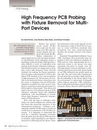
<strong>High</strong> <strong>Frequency</strong> Products<br />
FEATURED PRODUCTS<br />
Capacitors<br />
AVX Corp. introduced a series <strong>of</strong><br />
ultra-miniature chip capacitors for<br />
the RF and microwave communications<br />
market. Featuring copper<br />
electrodes in place <strong>of</strong> standard precious<br />
metal electrodes, the new CU<br />
Series chip capacitors provide extremely<br />
low ESR, high Q, and tight<br />
tolerances. Available in 01005 and<br />
0201 case sizes, the units are ideal<br />
for power amplifiers, handheld devices,<br />
GPS, vehicle location systems,<br />
and matching networks for wireless<br />
LANs.<br />
AVX Corp.<br />
avx.com<br />
and 400 watt models. <strong>The</strong>y are designed<br />
to deliver all the power required<br />
for applications using MIL-<br />
STD, DO 160, and other automotive<br />
standards. <strong>The</strong>se models can be<br />
used independently or with AR's<br />
RF conducted immunity generators<br />
when specific tests require higher<br />
powers than our standard CI Systems<br />
can generate.<br />
AR RF/Microwave <strong>Instrumentation</strong><br />
arworld.us<br />
are available in standard values <strong>of</strong><br />
3, 6, 10, 20, 30 and 40 dB and with<br />
Type N, SMA, 7/16-DIN or TNC connectors.<br />
Other dB values and custom<br />
connector configurations are<br />
available as options.<br />
Aer<strong>of</strong>lex/Inmet<br />
aer<strong>of</strong>lex.com<br />
Switch<br />
This RLC <strong>Electronics</strong>' Miniature<br />
Coaxial Switch is a single pole, two<br />
position type. <strong>The</strong> switch provides<br />
extremely high reliability, long life<br />
and excellent electrical performance<br />
characteristics over the frequency<br />
range <strong>of</strong> DC - 65 GHz. <strong>The</strong> miniature<br />
package utilizes high density<br />
packaging techniques, hence the<br />
overall volume <strong>of</strong> the switch is less<br />
than ¾ cubic inch.<br />
RLC <strong>Electronics</strong><br />
rlcelectronics.com<br />
RF Amp<br />
AR RF/Microwave <strong>Instrumentation</strong><br />
introduced a family <strong>of</strong> solid-state<br />
RF amplifiers that instantaneously<br />
covers the 10 kHz - 400 MHz frequency<br />
range with both 200 watt<br />
PIM Tester<br />
AWT Global launched a line <strong>of</strong><br />
portable Passive Intermodulation<br />
(PIM) Testers with an extended carrier<br />
power range: the PIM+ series.<br />
<strong>The</strong>se systems are equally suited<br />
for testing macro cells as well as<br />
outdoor and in-building DAS installations.<br />
While 2 x 20 W (2 x 43 dBm)<br />
carrier power is the reference for<br />
standard for PIM test systems, the<br />
new PIM+ <strong>of</strong>fers an extended adjustable<br />
power range <strong>of</strong> +15 dBm to<br />
+44 dBm for each carrier.<br />
AWT Global<br />
awt-global.com<br />
Attenuators<br />
Aer<strong>of</strong>lex/Inmet's improved 100 watt<br />
fixed attenuators are ideal for high<br />
power PA testing, load simulation<br />
and many other test environments.<br />
Inmet's 6N100W-XX operates from<br />
DC- 6 GHz, has excellent attenuation<br />
accuracy (30 dB +/- 1.5 dB) and<br />
a VSWR <strong>of</strong> less than 1.45:1. <strong>The</strong>y<br />
Resistors<br />
ATC announced the 504L Series<br />
next generation surface mount Ultra-Broadband<br />
Resistors. This new<br />
thin film product has been designed<br />
and manufactured with the highest<br />
quality materials to provide reliable<br />
and repeatable performance. It<br />
utilizes proprietary Glass Sandwich<br />
Flexiterm® Technology (GSFT). <strong>The</strong><br />
Flexiterm® is a surface-mountable<br />
automotive-qualified termination<br />
that adds an extra margin <strong>of</strong> safety<br />
against damage due to flexture during<br />
installation.<br />
American Technical Ceramics<br />
atceramics.com<br />
TCXO<br />
Rakon UK developed a 7.0 x 5.0<br />
mm small form factor acceleration<br />
tolerant TCXO. <strong>The</strong> RFPT705 is<br />
available with frequencies from 16<br />
to 40 MHz and uses patented dualcrystal<br />
design, giving better than<br />
0.5 ppb/g acceleration sensitivity.<br />
It is based on Rakon's proprietary<br />
PlutoTM TCXO ASIC, a single chip<br />
16 <strong>High</strong> <strong>Frequency</strong> <strong>Electronics</strong>
© 2012 AWR Corporation. All rights reserved.<br />
3D EM and<br />
circuit design in<br />
one integrated<br />
workflow<br />
Analyst 3D FEM EM simulator —<br />
seamlessly integrated within the<br />
Microwave Office environment —<br />
let’s you go from circuit concept<br />
to EM verification with one click.<br />
Spend your time designing, not<br />
drawing. It’s 3D EM power with<br />
Microwave Office efficiency. Grab a<br />
test copy at awrcorp.com/analyst.<br />
Stop waiting and start designing <br />
ANALYST<br />
3D FEM EM
<strong>High</strong> <strong>Frequency</strong> Products<br />
FEATURED PRODUCTS<br />
oscillator with an analog compensation<br />
circuit, which results in a frequency<br />
versus temperature stability<br />
as tight as ± 200 ppb. <strong>The</strong> design<br />
has a low component count, making<br />
it reliable for highly ruggedized environments.<br />
and power ranges. <strong>The</strong> terminations<br />
provide low VSWR terminations<br />
over a full range <strong>of</strong> RF frequencies.<br />
<strong>The</strong>se units utilize either<br />
a precision coaxial structure as the<br />
terminating element or a lossy dielectric<br />
medium. Heat transfer is<br />
accomplished efficiently by the utilization<br />
<strong>of</strong> cooling fins.<br />
RLC <strong>Electronics</strong><br />
rlcelectronics.com<br />
Rakon<br />
rakon.com<br />
EDA S<strong>of</strong>tware<br />
Agilent Technologies Inc. announced<br />
shipment <strong>of</strong> Advanced Design<br />
System 2012, its flagship RF<br />
and microwave EDA s<strong>of</strong>tware platform.<br />
ADS 2012 features new capabilities<br />
that improve productivity<br />
and efficiency for all applications<br />
the system supports and breakthrough<br />
technologies applicable to<br />
GaAs, GaN and silicon RF poweramplifier<br />
multichip module design.<br />
Limiters<br />
Herotek's product family (LL Series)<br />
<strong>of</strong> low leakage level limiters<br />
features a frequency range <strong>of</strong> 10<br />
MHz to 18 GHz with leakage levels<br />
as low as -10 dBm. This limiter<br />
product family has maximum input<br />
power handling capability <strong>of</strong> 1<br />
Watt CW and 100 Watt Peak power<br />
along with options for leakage levels<br />
<strong>of</strong> -10 dBm, -5 dBm, 0 dBm, or +5<br />
dBm. Bias <strong>of</strong> +5V is required with<br />
5mA typical current draw.<br />
Herotek<br />
herotek.com<br />
Agilent Technologies<br />
agilent.com<br />
Terminations<br />
RLC <strong>Electronics</strong>' precision coaxial<br />
terminations provide extremely low<br />
VSWR, 50 ohm matched terminations<br />
over broad frequency ranges<br />
in a wide selection <strong>of</strong> connectors<br />
3G Infrastructure Test<br />
Aer<strong>of</strong>lex Limited announced that<br />
the TM500 Test Mobile is the first<br />
to market to support full protocol<br />
stack UE (user equipment) emulation<br />
that enables network testing<br />
and measurements for the DC-<br />
HSUPA (Dual Cell <strong>High</strong>-Speed Upload<br />
Packet Access) standard specified<br />
in 3GPP W-CDMA Release 9.<br />
DC-HSUPA allows a UE to simul-<br />
Get info at www.HFeLink.com<br />
18 <strong>High</strong> <strong>Frequency</strong> <strong>Electronics</strong>
BETTER BUIlDInGS.<br />
BETTER CARE.<br />
For next-generation DAS,<br />
there’s only one name for passives.<br />
It’s simple. Better signals equal better care. Today’s hospitals personify<br />
the need for next-level Distributed Antenna Systems (DAS). And the<br />
engineers that are building them turn to MECA for passive components.<br />
American ingenuity and 52 years <strong>of</strong> experience have resulted in the deepest,<br />
most reliable product line <strong>of</strong> ready-to-ship and quick-turn solutions, such as:<br />
Power Dividers Up to 16 way and 18 GHz<br />
Attenuators Up to 60dB and 500W<br />
Terminations Up to 500W<br />
Couplers Up to 40dB and 1kW<br />
Integrated Rack Units Delivered in 3-6 weeks<br />
<strong>The</strong>y come with an industry leading 3 year guarantee and true MECA pride.<br />
Ready to build a better DAS? Start with a visit to www.e-MECA.com.<br />
Microwave Electronic Components <strong>of</strong> America<br />
<strong>The</strong> Pr<strong>of</strong>essional’s Choice for RF/Microwave Passive Components
<strong>High</strong> <strong>Frequency</strong> Products<br />
FEATURED PRODUCTS<br />
taneously transmit data over two<br />
independent enhanced uplink data<br />
channels, boosting both the uplink<br />
data rate and the network capacity,<br />
enabling maximum per-UE uplink<br />
data rates approaching 23 Mbps,<br />
effectively doubling the maximum<br />
rate.<br />
Aer<strong>of</strong>lex<br />
aer<strong>of</strong>lex.com<br />
Amplifier<br />
<strong>The</strong> GVA-60+ (RoHS compliant) is<br />
a wideband amplifier fabricated using<br />
HBT technology and <strong>of</strong>fering ultra<br />
flat gain over a broad frequency<br />
range and with high IP3. In addition,<br />
the GVA-60+ has good input<br />
and output return loss over a broad<br />
frequency range without the need<br />
for external matching components<br />
and has demonstrated excellent reliability.<br />
Lead finish is SnAgNi. It<br />
has repeatable performance from<br />
lot to lot and is enclosed in a SOT-<br />
89 package for very good thermal<br />
performance.<br />
Mini-Circuits<br />
minicircuits.com<br />
Transmitter<br />
MITEQ introduced a new high reliability<br />
Fiber Optic Transmitter with<br />
an operating bandwidth to 6 GHz.<br />
Model HRT-50K6G-28-20-M14 has<br />
a noise figure <strong>of</strong> 12 dB and is available<br />
in three different optical wavelengths<br />
(1550, 1490, 1310 nm). Operating<br />
temperature range is -40 to<br />
+85°C. With MITEQ’s line <strong>of</strong> fiber<br />
optic receivers it now is possible to<br />
have a complete fiber optic link that<br />
is sealed from the environment and<br />
has a spurious-free dynamic range<br />
<strong>of</strong> 103 dB/Hz. MITEQ has fiber optic<br />
links with operating bandwidths<br />
up to 20 GHz and all <strong>of</strong> its fiber optic<br />
links are available in a variety <strong>of</strong><br />
packaging options.<br />
MITEQ<br />
miteq.com<br />
An ISO 9001 Certified Company<br />
20 <strong>High</strong> <strong>Frequency</strong> <strong>Electronics</strong><br />
Get info at www.HFeLink.com<br />
HOW TO SUBMIT<br />
Product Releases to HFE<br />
To be considered for publication,<br />
please submit text in Word along<br />
with a 300 dpi min. color JPG image<br />
<strong>of</strong> your product. Submit to:<br />
tim@highfrequencyelectronics.com
When failure is not an option.<br />
Johnson’s line <strong>of</strong> SMP connectors are manufactured to MIL-Spec interface<br />
standards with consistent quality and performance levels you can depend on<br />
in your designs and applications.<br />
Emerson Network Power and the Emerson Network Power logo are trademarks and service<br />
marks <strong>of</strong> Emerson Electric Co. ©2011 Emerson Electric Co.<br />
Key benefits <strong>of</strong> using an SMP connector are:<br />
· Use blind-mate applications<br />
· Micro-miniature slide-on/snap-on interconnect system<br />
· Bullet design that provides a flexible link between shroud connections<br />
· Available in custom configurations<br />
Just another reason why Emerson Network Power is the<br />
global leader in enabling Business-Critical Continuity .<br />
EmersonConnectivity.com<br />
800-247-8256<br />
EMERSON. CONSIDER IT SOLVED.
<strong>High</strong> <strong>Frequency</strong> Design<br />
S<strong>of</strong>tware Revolution<br />
<strong>The</strong> <strong>Future</strong> <strong>of</strong> <strong>Instrumentation</strong>:<br />
<strong>The</strong> S<strong>of</strong>tware Revolution<br />
By Matthew Friedman<br />
Engineers are becoming<br />
empowered to make<br />
measurements and<br />
create test systems<br />
specifically suited to their<br />
exact needs.<br />
65 years ago Bell Labs<br />
forever changed technology<br />
with the invention <strong>of</strong><br />
the transistor. Considered<br />
one <strong>of</strong> the greatest inventions<br />
<strong>of</strong> the twentieth<br />
century, it is hard to find<br />
an element <strong>of</strong> our life<br />
that has not been impacted by its existence.<br />
This <strong>of</strong> course has had a pr<strong>of</strong>ound impact on<br />
instrumentation as well. Companies like<br />
Hewlett-Packard were born from this silicon<br />
revolution and their instruments replaced the<br />
vacuum tube instruments <strong>of</strong> General Radio<br />
before them. Like 45 years ago, we are now at<br />
another crossroads in instrumentation with<br />
the s<strong>of</strong>tware revolution. Just as everyone<br />
expects their smartphone to have apps customized<br />
to their exact needs, engineers are<br />
struggling to make do with fixed functionality<br />
instruments. As we stand at the precipice <strong>of</strong><br />
this new era, we are seeing a fundamental<br />
shift as engineers are becoming empowered to<br />
make measurements and create test systems<br />
specifically suited to their exact needs.<br />
Test Complexity Drives Change in<br />
<strong>Instrumentation</strong><br />
With increased technological innovation<br />
comes the challenge <strong>of</strong> testing each new<br />
breakthrough. For example, as wireless standards<br />
become more complex, the number <strong>of</strong><br />
operational modes for these devices increases<br />
exponentially. As we progress to the latest<br />
WiFi standards like 802.11ac, there are many<br />
new modulation schemes, additional channels,<br />
more bandwidth settings, and extra spatial<br />
streams that increase testing complexity.<br />
Additionally, characterizing WLAN transceivers<br />
is especially challenging when faced with<br />
thousands <strong>of</strong> independent operational gain<br />
settings (Figure 1).<br />
With such complexity, manual testing techniques<br />
become infeasible and some level <strong>of</strong><br />
automation is required. This is traditionally<br />
achieved by connecting box instruments over<br />
22 <strong>High</strong> <strong>Frequency</strong> <strong>Electronics</strong><br />
Figure 1 • An example block diagram <strong>of</strong> a typical WLAN receiver shows how each<br />
component has multiple gain stages, resulting in hundreds <strong>of</strong> thousands <strong>of</strong> different possible<br />
gain settings for a single receiver. (Courtesy <strong>of</strong> Qualcomm Atheros).
NEW<br />
30 day<br />
MONEY-BACK<br />
Try it! If not satisfed, call for RMA# and return<br />
in original packaging. Web sales only, terms<br />
and conditions apply, see minicircuits.com/30day<br />
Smart<br />
SyntheSized<br />
Signal generatorS<br />
Rugged, portable, production test workhorses<br />
Sweep or hop across wide frequency and power bands, use<br />
a pair for third-order intercept tests, or slip one into your<br />
laptop case and take it on the road! Our easy-to-use GUI will<br />
have you up and running in minutes. Compatible with most<br />
test s<strong>of</strong>tware,* they add capabilities and increase efficiency,<br />
all without busting your budget!<br />
*See data sheets for an extensive list <strong>of</strong> compatible s<strong>of</strong>tware.<br />
250-4000 MHz<br />
GUARANTEE!<br />
WOW!<br />
$<br />
1995 00<br />
only<br />
ea.<br />
Accurate, reliable results at high speed<br />
Signals within 1 ppm for frequency and 0.25 dBm for power, low<br />
harmonics, a resolution <strong>of</strong> 5 kHz, and 5-msec settling times<br />
help you get the data you need from complex, high-speed<br />
testing plans. Just go to minicircuits.com for specifications,<br />
performance data, and everything you need to make your<br />
choice — and get it in your hands as soon as tomorrow!<br />
dBm<br />
-5<br />
-15<br />
-25<br />
-35<br />
-45<br />
-55<br />
-65<br />
-75<br />
-85<br />
Model <strong>Frequency</strong> Power Harmonics Price<br />
(MHz) (dBm) (dBc typ.) ($ ea.)<br />
SSG-4000HP 250-4000 -50 to +20 -40 1995.00<br />
SSG-4000LH 250-4000 -60 to +10 -66 2395.00<br />
<strong>Frequency</strong> and power hopping.<br />
Low spurious.<br />
Mini-Circuits...we’re redefining what VALUE is all about!<br />
®<br />
U.S. Patents<br />
7739260, 7761442<br />
ISO 9001 ISO 14001 AS 9100<br />
®<br />
P.O. Box 350166, Brooklyn, New York 11235-0003 (718) 934-4500 Fax (718) 332-4661<br />
<strong>The</strong> Design Engineers Search Engine finds the model you need, Instantly • For detailed performance specs & shopping online see<br />
IF/RF MICROWAVE COMPONENTS<br />
499 rev C
<strong>High</strong> <strong>Frequency</strong> Design<br />
S<strong>of</strong>tware Revolution<br />
an instrument control interface to a computer, and then<br />
using a s<strong>of</strong>tware application to automate the system.<br />
While these systems have been functional, they are <strong>of</strong>ten<br />
inefficient and do not apply the instrument as they are<br />
intended to be used.<br />
Traditional box instruments are designed for when an<br />
engineer or technician wants to manually test or troubleshoot<br />
a device. When automation is required, the instruments’<br />
screens, knobs, and buttons can <strong>of</strong>ten become a<br />
waste <strong>of</strong> space and money. Furthermore, these instruments<br />
are not typically designed to maximize measurement<br />
speed or data throughput.<br />
<strong>The</strong> Move to PXI Modular Instruments<br />
Over the last few years, the industry reached a tipping<br />
point and is making the switch to PXI. Optimized<br />
for automating measurements, PXI provides a solution<br />
that is <strong>of</strong>ten faster, smaller, and more cost-effective than<br />
traditional box instruments. For example, TriQuint<br />
Semiconductor saw their testing complexity massively<br />
increase as they had to characterize their latest generation<br />
RF power amplifiers over a wide range <strong>of</strong> frequencies,<br />
voltage supply levels, temperatures and power<br />
ranges. For the typical part, this requires 30,000 –<br />
40,000 lines <strong>of</strong> data to completely test the design. Using<br />
traditional box instruments, a full characterization would<br />
take about two weeks to complete. By making the switch<br />
to PXI modular instruments for the bulk <strong>of</strong> their measurements,<br />
Triquint was able to significantly reduce testing<br />
times (Figure 2) and complete full characterization in<br />
about a day.<br />
Based on commercial, <strong>of</strong>f-the-shelf technology, PXI<br />
provides a solution that is faster, smaller and more cost<br />
effective than traditional solutions. Some <strong>of</strong> the key features<br />
include (Figure 3):<br />
Small, modular architecture: PXI modules are<br />
available from DC to 26.5 GHz and can be mixed and<br />
matched to create a full test system in a small benchtop<br />
footprint or 3U <strong>of</strong> rack space.<br />
<strong>High</strong> throughput data transfer: Based on the PCI<br />
Express bus, PXI is able to achieve data transfers more<br />
than 20 times faster with 100 times less latency than<br />
traditional instrument control interface like Ethernet<br />
and GPIB.<br />
Figure 2 • Triquint Semiconductor realizes test speeds 6<br />
to 14 times faster using PXI modular instruments over<br />
traditional instruments.<br />
Figure 3 • <strong>The</strong> PXI platform is ideally suited to meet<br />
today’s and tomorrow’s testing needs.<br />
Upgradeable, modular controllers: Engineers can<br />
add extra processing capabilities by simply swapping the<br />
controller while keeping the same chassis and instrumentation.<br />
For example, to improve performance, they can<br />
easily switch a system built in 2001 operating at 2.5<br />
GFLOPS with a controller running the latest Intel core i7<br />
processor at over 35 GFLOPS.<br />
Integrated timing and synchronization: PXI<br />
chassis incorporate dedicated 10 and 100 MHz reference<br />
clock and trigger lines to every slot to address the needs<br />
<strong>of</strong> synchronizing multichannel and MIMO test systems.<br />
<strong>The</strong> PXI market has grown immensely since its introduction<br />
15 years ago. According to Frost and Sullivan, it<br />
is expected to be over billion-dollar market by 2017.<br />
Already today there are more than 70 companies with<br />
more than 2,000 different products.<br />
<strong>The</strong> Revolution <strong>of</strong> S<strong>of</strong>tware<br />
While PXI provides a faster, smaller, and more costeffective<br />
option, its real power lies in allowing the user to<br />
create test systems better suited to their exact needs. For<br />
example, ST Ericsson had the challenge <strong>of</strong> the increasing<br />
complexity <strong>of</strong> testing their latest RF platforms for mobile<br />
phones and tablets. <strong>The</strong>se platforms containing multiple<br />
radios, such as GPS, Bluetooth, WCDMA, and LTE,<br />
require approximately 800,000 measurements to fully<br />
test. Further complicating the tests is that they must<br />
work with multiple standards and custom digital protocols<br />
to properly interface their chips. When traditional<br />
box instruments proved not to be flexible enough to meet<br />
their needs, ST Ericsson turned to NI LabVIEW system<br />
design s<strong>of</strong>tware and NI PXI hardware to perform the<br />
needed DUT interfacing, RF measurements and analysis.<br />
Not only was the system much more flexible, ST Ericsson<br />
was able to reduce test time by a factor <strong>of</strong> 10, from 3 days<br />
to 8 hours.<br />
24 <strong>High</strong> <strong>Frequency</strong> <strong>Electronics</strong>
Figure 4 • <strong>The</strong> NI PXIe-5644R is the world’s first s<strong>of</strong>twaredesigned<br />
instrument.<br />
However, even with all this flexibility, there is <strong>of</strong>ten a<br />
need for more. For example, many new tests require<br />
capabilities like frequency domain triggering, real-time<br />
spectral masks and embedded control algorithms. <strong>The</strong>se<br />
tasks can be difficult to execute as they are required to be<br />
directly executed within the instrument’s embedded firmware<br />
and typically must be implemented by the vendor.<br />
Fortunately, there is a new paradigm in instrumentation<br />
called s<strong>of</strong>tware-designed instruments that opens up the<br />
instrument’s firmware and allows the engineer complete<br />
access to add their required functionality.<br />
<strong>The</strong> first instrument to support this paradigm is the<br />
NI PXIe-5644R vector signal transceiver (Figure 4).<br />
Combining a vector signal analyzer, a vector signal generator<br />
and high-speed digital I/O in one three-slot PXI<br />
module, the NI PXIe-5644R vector signal transceiver is a<br />
fraction <strong>of</strong> the size and cost <strong>of</strong> traditional solutions while<br />
maintaining industry-leading measurement performance.<br />
What makes it a s<strong>of</strong>tware-designed instrument is that is<br />
has an open, user-programmable FPGA at its core. Users<br />
can modify its s<strong>of</strong>tware and firmware, which is based on<br />
LabVIEW, to create an instrument specific to their needs.<br />
Out <strong>of</strong> the box, the vector signal transceiver provides a<br />
s<strong>of</strong>tware experience similar to other instruments with a<br />
quick time to first measurement/generation and a programming<br />
interface for the most common functions.<br />
However, the true power comes from the fact that all<br />
LabVIEW s<strong>of</strong>tware and firmware source code is provided<br />
to enable users to modify their instruments to their specific<br />
needs. System design s<strong>of</strong>tware like LabVIEW is well<br />
suited to s<strong>of</strong>tware designed-instruments because it is<br />
capable <strong>of</strong> abstracting the processing implemented on an<br />
FPGA and the microprocessor on the PXI controller in a<br />
way that does not require extensive knowledge <strong>of</strong> computing<br />
architectures and data manipulation. This frees the<br />
user to focus on the functionality <strong>of</strong> algorithms and instrument<br />
control to meet their specific application needs.<br />
Qualcomm Atheros is one <strong>of</strong> the initial users <strong>of</strong> the<br />
s<strong>of</strong>tware-designed vector signal transceiver in the testing<br />
<strong>of</strong> their latest 802.11ac WLAN transceiver. <strong>The</strong>y were<br />
faced with the challenge <strong>of</strong> their latest designs having<br />
multiple gain settings at each stage <strong>of</strong> the radio structure.<br />
This resulted in hundreds <strong>of</strong> thousands <strong>of</strong> data points that<br />
needed to be acquired for a single operational mode. Using<br />
traditional instruments it was not feasible to perform all<br />
these measurement and instead used a best estimate gain<br />
table that would only produce approximately 40 meaningful<br />
data points per iteration. However, after making the<br />
switch to the vector signal transceiver, they were able to<br />
Figure 5 • Qualcomm Atheros realized a 200 times improvement in measurement speed and a better<br />
understanding <strong>of</strong> their devices after making the switch to the vector signal transceiver.<br />
25
<strong>High</strong> <strong>Frequency</strong> Design<br />
S<strong>of</strong>tware Revolution<br />
Figure 6 • Embedding power amplifier servoing control<br />
algorithms directly in the instrument can provide over<br />
an 800 times reduction in test time.<br />
perform DUT control and data processing directly within<br />
the instrument. This resulted in 200 times improvement<br />
in measurement speed and also allowed a test sweep to<br />
acquire all 300,000 data points for a better determination<br />
<strong>of</strong> optimal operational settings (Figure 5).<br />
Examples <strong>of</strong> S<strong>of</strong>tware-Designed Instrument Applications<br />
With s<strong>of</strong>tware designed-instruments, engineers are<br />
empowered to create the instrument specifically suited to<br />
their exact needs. Early users <strong>of</strong> the vector signal transceiver<br />
are already customizing it in many different ways;<br />
two recent examples are those <strong>of</strong> power amplifier servoing<br />
and channel emulation.<br />
Example: Power-Level Servoing for Power Amplifier Test<br />
It is important for power amplifiers (PAs) to have an<br />
expected output power, even outside their linear operating<br />
modes. To accurately calibrate a PA, a power-level<br />
servo feedback loop is used to determine the final gain.<br />
Power-level servoing captures the current output power<br />
with an analyzer and controls the<br />
generator power level until desired<br />
power is achieved, which can be a<br />
time-consuming process. In simplest<br />
terms, it uses a proportional<br />
control loop to swing back and<br />
forth in power levels until the output<br />
power-level converges with the<br />
desired power. <strong>The</strong> vector signal<br />
transceiver is ideal for power-level<br />
servoing because the process can<br />
be implemented directly on the<br />
user-programmable FPGA, resulting<br />
in a much faster convergence<br />
on the desired output power value<br />
(Figure 6).<br />
increases and radio spectrums are becoming more crowded,<br />
it becomes important to not only test wireless devices<br />
in a static environment, but to understand how these<br />
devices behave in a dynamic real-world environment. A<br />
radio channel emulator is a tool for emulating wireless<br />
communication in a real-world environment. Fading<br />
models are used to simulate air interference, reflections,<br />
moving users, and other naturally occurring phenomenon<br />
that can hamper an RF signal in a physical radio<br />
environment. By programming these mathematical fading<br />
models onto the FPGA <strong>of</strong> the vector signal transceiver,<br />
the module can be reconfigured to go beyond a<br />
traditional VSA/VSG paradigm and become an embedded<br />
device providing real-time impairments <strong>of</strong> your RF<br />
signals (Figure 7).<br />
With s<strong>of</strong>tware-designed instruments, the user is truly<br />
able to create the instrument specifically designed to<br />
their exact needs. Already, we are seeing unique and<br />
novel ways to apply this concept and overcome the challenges<br />
<strong>of</strong> instrumentation defined by the vendor. <strong>The</strong><br />
future will always hold new testing challenges but we can<br />
be confident that a user empowered with s<strong>of</strong>twaredesigned<br />
instruments will be able to rise to the occasion.<br />
About the Author:<br />
Matthew Friedman is the Senior Product Manager for<br />
the RF and Microwave platform at National Instruments.<br />
Prior to his current position, Matthew was the product<br />
manager for instrument control s<strong>of</strong>tware. Along with his<br />
work at National Instruments, he is active in test & measurement<br />
standards bodies. He serves as a director and<br />
marketing co-chairman in the PXI Systems Alliance and<br />
was previously the marketing chairman <strong>of</strong> the IVI<br />
Foundation.<br />
Example: Radio Channel Emulation<br />
As RF modulation schemes are<br />
growing in complexity, bandwidth<br />
26 <strong>High</strong> <strong>Frequency</strong> <strong>Electronics</strong><br />
Figure 7 • S<strong>of</strong>tware-designed instruments can be reconfigured into embedded<br />
devices like channel emulators to aid in the understanding <strong>of</strong> how<br />
devices will work in real-world environments.
QUALITY, PERFORMANCE AND RELIABILITY<br />
IN PRECISION COAXIAL CONNECTORS<br />
EDGE LAUNCH<br />
CONNECTORS<br />
BETWEEN SERIES<br />
ADAPTERS<br />
BULKHEAD & PANEL<br />
ADAPTERS<br />
IN SERIES ADAPTERS<br />
CABLE CONNECTORS<br />
CUSTOM DESIGNS<br />
ADAPTERS · CABLE CONNECTORS · RECEPTACLES · CUSTOM DESIGNS<br />
1.85mm<br />
2.4mm<br />
Including <strong>The</strong>se Connector Series<br />
DC-65 GHz 2.92mm DC-40 GHz 7mm<br />
DC-50 GHz 3.5mm DC-34 GHz SSMA<br />
DC-18 GHz<br />
DC-40 GHz<br />
ISO 9001:2008<br />
SGMC Microwave — <strong>The</strong> name to count on for Quality, Performance<br />
and Reliability! Please contact us today by Phone, Fax or Email.<br />
Manufacturer <strong>of</strong> Precision Coaxial Connectors<br />
620 Atlantis Road, Melbourne, FL 32904<br />
Phone: 321-409-0509 Fax: 321-409-0510<br />
sales@sgmcmicrowave.com<br />
www.sgmcmicrowave.com<br />
Get info at www.HFeLink.com
<strong>High</strong> <strong>Frequency</strong> Design<br />
IF Processor<br />
Design, Construction and<br />
Characterization <strong>of</strong> an IF<br />
Processor for the FFT<br />
Spectrometer <strong>of</strong> the Yebes<br />
40 Meter Radio Telescope<br />
By José Antonio López-Pérez and David Cuadrado-Calle;<br />
Centro Astronómico de Yebes (CAY)<br />
Describes the design,<br />
construction and<br />
characterization <strong>of</strong> an IF<br />
processor for the<br />
adaptation <strong>of</strong> the IF<br />
signal frequency range<br />
<strong>of</strong> radio astronomy<br />
receivers.<br />
Abstract<br />
<strong>The</strong> radio astronomy<br />
receivers installed in the<br />
receiver room <strong>of</strong> the 40<br />
meter radio telescope at<br />
the Spanish Centro<br />
Astronómico de Yebes<br />
(CAY) provide an intermediate<br />
frequency (IF)<br />
signal in the standard<br />
Very Long Base-Line Interferometry (VLBI)<br />
frequency range from 500 MHz to 1000 MHz.<br />
For single-dish observations, the IF signal<br />
must be sent to the Fast Fourier Transform<br />
spectrometer (FFTS) placed in the backend<br />
room <strong>of</strong> the radio telescope. This spectrometer<br />
is configurable in four different resolution<br />
modes that correspond to four different base<br />
band input frequency ranges. As the FFTS<br />
base band frequency input range doesn’t<br />
match with the IF signal range from the<br />
receivers, a frequency down conversion is<br />
needed and it is provided by an analogue IF<br />
processor.<br />
<strong>The</strong> present work shows the design, construction<br />
and characterization <strong>of</strong> an<br />
IF processor for the adaptation <strong>of</strong><br />
the IF signal frequency range <strong>of</strong> the<br />
radio astronomy receivers to two <strong>of</strong><br />
the Fast Fourier Transform spectrometer<br />
input frequency ranges.<br />
<strong>The</strong>se frequency ranges are the one<br />
between DC and 100 MHz and the one between<br />
DC and 500 MHz.<br />
<strong>The</strong> processor is made <strong>of</strong> commercial <strong>of</strong>fthe-shelf<br />
(COST) components (amplifiers, filters,<br />
mixers, etc.) and it has been integrated<br />
inside a standard 19” 2U rack with 2 inputs<br />
for the receivers’ IF signals (LHCP and RHCP<br />
channels), 2 outputs for the DC-100 MHz<br />
range and 2 outputs for the DC-500 MHz one.<br />
<strong>The</strong> resulting processor has been tested showing<br />
input and output return losses better than<br />
13 dB and 15 dB, respectively, a mean power<br />
gain <strong>of</strong> 25 dB (± 1.5 dB) in its linear zone and<br />
an output power <strong>of</strong> +10 dBm at -1 dB gain<br />
compression point.<br />
Introduction<br />
<strong>The</strong> CAY 40 meter radio telescope is<br />
equipped with a Fast Fourier Transform spectrometer,<br />
so-called FFTS, from Radiometer<br />
Physics GmbH, for the detection and observation<br />
<strong>of</strong> molecular lines in single-dish mode.<br />
<strong>The</strong> spectrometer has eight modules, each<br />
one configurable during booting in any <strong>of</strong> the<br />
operation modes described in Table 1.<br />
Table 1 • Operation modes <strong>of</strong> the FTTS <strong>of</strong> the 40 m radio<br />
telescope. * ENBW = Equivalent Noise Band Width.<br />
28 <strong>High</strong> <strong>Frequency</strong> <strong>Electronics</strong>
COMPLIANT<br />
LAVI<br />
VERY LOW DISTORTION<br />
MIXERS<br />
+36 dBm IP3 2 to 3100 MHz<br />
Mini-Circuits shielded LAVI frequency mixers deliver the breakthrough combination <strong>of</strong> very high<br />
IP3 and IP2, ultra-wideband operation, and outstanding electrical performance. By combining our<br />
advanced ceramic, core & wire, and semi-conductor technologies, we’ve created these evolutionary<br />
patented broadband mixers that are specially designed to help improve overall dynamic range.<br />
With a wide selection <strong>of</strong> models, you’ll find a LAVI mixer optimized for your down converter and<br />
up converter requirements. Visit the Mini-Circuits website at www.minicircuits.com for comprehensive<br />
performance data, circuit layouts, and environmental specifications. Price & availability for on-line<br />
ordering is provided for your convenience.<br />
Check these LAVI Mixer outstanding features!<br />
• Very wide band, 2 to 3100 MHz<br />
• Ultra high IP2 (+60 dBm) and IP3 (+36 dBm)<br />
• -73 dBc harmonic rejection 2LO-2RF, 2RF-LO<br />
RoHS compliant<br />
o<br />
S<br />
$<br />
from9 95 ea.<br />
qty. 1000<br />
• Super high isolation, up to 52 dB<br />
• <strong>High</strong> 1 dB compression, up to +23 dBm<br />
• Extremely low conversion loss, from 6.3 dB<br />
U.S. Patent Number 6,807,407<br />
Mini-Circuits…we’re redefining what VALUE is all about!<br />
®<br />
U.S. Patents<br />
7739260, 7761442<br />
ISO 9001 ISO 14001 AS 9100<br />
®<br />
P.O. Box 350166, Brooklyn, New York 11235-0003 (718) 934-4500 Fax (718) 332-4661<br />
<strong>The</strong> Design Engineers Search Engine finds the model you need, Instantly • For detailed performance specs & shopping online see<br />
IF/RF MICROWAVE COMPONENTS<br />
451 Rev J
<strong>High</strong> <strong>Frequency</strong> Design<br />
IF Processor<br />
As the receivers installed in the radio telescope have<br />
their IF in the range between 500 and 1000 MHz, according<br />
to the specifications for standard VLBI receivers, a<br />
previous unit for down conversion to the FFTS input frequency<br />
range is needed, particularly for C and D modes,<br />
where the narrower resolutions can be achieved.<br />
Figure 1 • Block diagram <strong>of</strong> the IF processor and power<br />
levels.<br />
Design<br />
Figure 1 shows the block diagram <strong>of</strong> the IF processor.<br />
<strong>The</strong> processor is composed <strong>of</strong> two equal conversion chains<br />
(one for each circular polarization sense, LHCP and<br />
RHCP, according to VLBI standards) and one common<br />
local oscillator (LO) at 500 MHz that enables the necessary<br />
frequency down-conversion.<br />
<strong>The</strong> IF input signals are amplified and filtered in the<br />
500 MHz to 1000 MHz range, before reaching the mixer,<br />
to filter out unwanted signals and noise. One sample <strong>of</strong><br />
the input signal is sent to an auxiliary output by means<br />
<strong>of</strong> a power splitter. This is to allow the connection <strong>of</strong> other<br />
devices for analysis (backends, Mk-4 terminal...) or diagnosis<br />
(spectrum analyzer). After the mixer, the signal,<br />
which is now in base band, is divided into two ways and<br />
amplified again. <strong>The</strong>n one way is low-pass filtered to DC<br />
- 100 MHz and the other to DC - 500 MHz.<br />
Integration<br />
All the components shown in the block diagram <strong>of</strong><br />
Figure 1 have been integrated in a standard 19’’ 2U rack.<br />
Figure 2 shows the final look <strong>of</strong> the processor.<br />
Laboratory Measurements <strong>of</strong> the IF Processor<br />
Return losses <strong>of</strong> the input ports<br />
Figure 3 shows the result <strong>of</strong> the S11 parameter measurement<br />
in the input ports <strong>of</strong> both LHCP and RHCP<br />
channels <strong>of</strong> the IF processor.<br />
It can be seen that both channels have a good input<br />
matching in the frequency range between 500 and 1000<br />
MHz with return losses better than 13 dB.<br />
Get info at www.HFeLink.com<br />
Figure 2 • Integrated IF processor.<br />
30 <strong>High</strong> <strong>Frequency</strong> <strong>Electronics</strong>
Solid State Switch Matrices & Switching Networks to 40GHz<br />
Amplifiers<br />
Attenuators - Variable<br />
DLVA & ERDLVA &<br />
SDLVA’s<br />
DTO’s<br />
Filters<br />
Form, Fit & Function<br />
Products<br />
Hybrids, Dividers &<br />
Couplers<br />
IFM’s & <strong>Frequency</strong><br />
Discriminators<br />
Integrated MIC/MMIC<br />
Modules<br />
I/Q Vector Modulators<br />
Limiters & Detectors<br />
Log Amplifiers<br />
SWITCH MATRICES & SWITCHING NETWORKS<br />
HANDOVER TEST SYSTEMS<br />
RF SWITCH ASSEMBLIES<br />
PROGRAMMABLE ATTENUATOR ASSEMBLIES<br />
BLOCKING & NON-BLOCKING<br />
FAN-IN & FAN-OUT CONFIGURATIONS<br />
BIDIRECTIONAL<br />
RS-232, RS422/485, PECL, ETHERNET, USB, TOUCH SCREEN &<br />
OTHER CONTROL SYSTEMS AVAILABLE<br />
OTHER INTEGRATED FUNCTIONS AVAILABLE:<br />
PHASE SHIFTING, PULSE MODULATION, DETECTION, ATTENUATION,<br />
RF FILTERING, ETC.<br />
LINUX OR WINDOWS OPERATING SYSTEMS, MODULAR DESIGNS, PLUG &<br />
PLAY, REMOVABLE COMPACT FLASH WITH BOOT AND OPERATING<br />
SOFTWARE<br />
CUSTOM DESIGNS AVAILABLE TO SUIT YOUR APPLICATION NEEDS<br />
PMI STANDARD SWITCH MATRICES<br />
Pulse & Bi-Phase<br />
Modulators<br />
Phase Shifters<br />
Rack & Chassis Mount<br />
Products<br />
Receiver Front Ends<br />
Single Sideband<br />
Modulators<br />
SMT & QFN Products<br />
Solid-State Switches<br />
Switch Matrices<br />
Switch Filter Banks<br />
Threshold Detectors<br />
USB Products
<strong>High</strong> <strong>Frequency</strong> Design<br />
IF Processor<br />
Figure 3 • LHCP (a) and RHCP (b)<br />
input ports return losses.<br />
Figure 4 • Return losses <strong>of</strong> the output ports LHCP DC-100 MHz (a), RHCP<br />
DC-100 MHz (b), LHCP DC-500 MHz (c), RHCP DC-500 MHz (d).<br />
Return loss <strong>of</strong> the output ports<br />
Figure 4 shows the return losses <strong>of</strong> the output ports <strong>of</strong><br />
the processor.<br />
According to these measurements, the return losses at<br />
the output ports are better than 15 dB through all the<br />
output frequency range.<br />
Gain curves and 1 dB compression point<br />
In order to determine the processor’s gain, a power<br />
sweep has been carried out at several frequencies <strong>of</strong> the<br />
input signal. <strong>The</strong> resulting gain curves are represented in<br />
Figure 5.<br />
According to these graphs, both channels have a gain<br />
<strong>of</strong> 25 dB (± 1.5 dB) on their linear zone.<br />
<strong>The</strong> output power at -1 dB gain compression <strong>of</strong> the<br />
processor has been calculated for the wideband output <strong>of</strong><br />
both LHCP and RHCP channels. <strong>The</strong> computations have<br />
been carried out at 950 MHz, and the results are shown<br />
in Figure 6.<br />
Hence, it can be considered that the output power at -1<br />
dB compression is +11 dBm for the LHCP channel and<br />
+10 dBm for the RHCP channel. As the processor has a<br />
mean gain <strong>of</strong> 25 dB and it is highly recommended to leave<br />
a security margin <strong>of</strong> 5 dB at least, the maximum recommended<br />
input power to the processor is -20 dBm.<br />
Installation in the Radio Telescope<br />
Once the processor has been completely characterized<br />
in terms <strong>of</strong> matching, power levels and gain, it has been<br />
32 <strong>High</strong> <strong>Frequency</strong> <strong>Electronics</strong><br />
Figure 5 • Gain curves.
Rosenberger ® Rmor Cables Assembly<br />
PHASE STABLE THROUGH 70GHz<br />
Rosenberger Rmor cables are designed for rugged<br />
environments for indoor and outdoor applications. Each<br />
shielded coaxial cable is protected with flexible, SPIRALwound<br />
304 Stainless Steel armor coated with extruded<br />
Polyurethane. <strong>The</strong> connector ends are sealed and encapsulated<br />
with a pressure injection-molded polymer strain relief.<br />
This combination <strong>of</strong> materials and technology provides<br />
superior ruggedization, environmental resistance, RF<br />
shielding effectiveness and stability under flexure and<br />
vibration.<br />
Additional connector interfaces and armor/cable<br />
diameters are available on request.<br />
DESCRIPTION<br />
Rosenberger connectors, cable assembly, standard length 915mm<br />
or 36 inches<br />
GENERAL ELECTRICAL SPECIFICATIONS<br />
Impedance:<br />
Operating frequency:<br />
Return loss:<br />
Cable insertion loss:<br />
Velocity <strong>of</strong> propagation (%):<br />
Capacitance:<br />
Shielding effectiveness:<br />
Dielectric withstand voltage:<br />
Amplitude & phase stable:<br />
50 +/- 1 Ohms<br />
DC to 70 GHz<br />
14 dB minimum up to 70 GHz<br />
.67 dB/ft @ 10.0 GHz<br />
78 % nominal<br />
24.7 pf/ft. nominal<br />
< -90 dB<br />
1000 Vrms<br />
+/- .03dB & +/- 1° @10GHz<br />
MECHANICAL SPECIFICATION<br />
Cable jacket & armor outer diameter:<br />
Minimum bend radius:<br />
Armor crush strength:<br />
Connector retention:<br />
Mating torque:<br />
MATERIALS AND FINISHES<br />
Armor type:<br />
Connector environmental testing:<br />
Connector interface dimension:<br />
Note: Cable assemblies also available with interfaces such as 1.85mm, 2.4mm, 2.92mm, SMA +, SMA, N.<br />
092 inches nominal &<br />
.250 inches nominal<br />
.5 inches<br />
450 lbs/in (min)<br />
≥25 lbs.<br />
7-10 inch pounds<br />
SPIRAL-wound 304 SS &<br />
Polyurethane blue jacket<br />
Per MIL-STD-202,<br />
Meth 101,106,107,204 & 213<br />
IEC 60169-17 Per MIL-<br />
PRF-39012 DINEN122200<br />
IN STOCK!<br />
Try anRmorcablewith<br />
SMA + (operatesto36GHz)<br />
Call RFMWtoday<br />
877.367.7369.Askforp/n<br />
R71-32+S132+S1-00457 (18”)<br />
<br />
70GHz Cables<br />
1.85mm males each end<br />
Call RFMW today for P&D<br />
877.367.7369<br />
RU5-08S1-08S1-00610 (2 feet)<br />
RU5-08S1-08S1-00915 (3 feet)<br />
RU5-08S1-08S1-01220 (4 feet)<br />
Example <strong>of</strong> typical 36 inches assembly up to 70 GHz<br />
RFMW is the exclusive stocking distributor for Rosenberger ®<br />
Connectors and Cable Assemblies<br />
RFMW, 188 Martinvale Lane, San Jose, CA 95119<br />
PH: 408.414.1450 or 877.367.7369 Email: sales@rfmw.com<br />
Website: www.rfmw.com/Rosenberger
<strong>High</strong> <strong>Frequency</strong> Design<br />
IF Processor<br />
Figure 7. Front view <strong>of</strong> the IF processor (bottom rack)<br />
installed in the backend room below the FFTS.<br />
Figure 6. Linearity <strong>of</strong> the IF processor.<br />
installed in the backend room <strong>of</strong> the Yebes 40 meter radio<br />
telescope.<br />
As it is shown in Figure 7, the IF processor has been<br />
installed in the same rack as the FFT spectrometer, just<br />
below it.<br />
Measurements in the Backend Room<br />
In order to measure the behaviour <strong>of</strong> the IF processor<br />
in the backend room, an additive white gaussian noise<br />
(AWGN) generator has been used together with a band<br />
pass filter between 500 MHz and 1000 MHz. This system<br />
provides a signal with similar characteristics than the<br />
astronomical one. <strong>The</strong> set AWGN generator plus filter has<br />
been characterized according to the set-up shown in<br />
Figure 8.<br />
Once the level <strong>of</strong> the test signal has been measured, it<br />
has been injected in the IF processor where the power<br />
levels and the spectrum <strong>of</strong> each output port have been<br />
measured. <strong>The</strong> test bench used for carrying out these<br />
measurements is shown in Figure 9.<br />
<strong>The</strong> power level values obtained at each output port<br />
are shown in Table 2.<br />
Figure 10 shows the spectrum <strong>of</strong> the input signal and<br />
the ones obtained at the monitoring ports, the DC-100<br />
MHz outputs and the DC-500 MHz outputs. <strong>The</strong>se spectra<br />
have been obtained with the spectrum analyzer configured<br />
with 10 dB/div and a resolution bandwidth <strong>of</strong> 1<br />
MHz.<br />
Dynamic Power Range<br />
<strong>The</strong> FFTS has a power detector and a LED diode indicator<br />
on each module that allows one to know whether<br />
the power at the input <strong>of</strong> the analogue-to-digital converter<br />
(ADC) is optimum or not. This detection system,<br />
together with the AWGN generator, have enabled several<br />
tests to find out the optimum power range at the input <strong>of</strong><br />
the IF processor for the suitable operation <strong>of</strong> the set IF<br />
processor plus FFTS. Table 3 shows the results.<br />
Figure 8 • Test signal characterization.<br />
Figure 9 • Test bench for the IF processor measurements<br />
in the backend room.<br />
34 <strong>High</strong> <strong>Frequency</strong> <strong>Electronics</strong>
Table 2 • Power level values at the output ports.<br />
Conclusions<br />
An analogue IF processor has been designed, built<br />
and characterized in Yebes laboratories to adapt the output<br />
signal <strong>of</strong> the 40 meter radio telescope VLBI receivers<br />
to the input frequency range <strong>of</strong> the FFT spectrometer<br />
(modes C and D).<br />
<strong>The</strong> final performance <strong>of</strong> the IF processor is summarized<br />
as follows:<br />
• <strong>The</strong> input and output return losses are always better<br />
than 13 dB and 15 dB, respectively.<br />
• <strong>The</strong> processor has a mean power gain <strong>of</strong> approximately<br />
25 dB (± 1.5 dB) on its linear zone.<br />
• <strong>The</strong> output power at -1 dB compression point is +11<br />
dBm for the LHCP channel and +10 dBm for the<br />
RHCP channel.<br />
Figure 11 • Uncalibrated spectrum <strong>of</strong> SiO maser<br />
emission at 86 GHz from IK-Tau star.<br />
Table 3 • Power levels study for the proper operation <strong>of</strong> the FFTS.<br />
Figure 10 • Spectrum on each port <strong>of</strong> the IF processor<br />
in the backend room.<br />
Currently, the processor is installed in the backend<br />
room <strong>of</strong> the radio telescope. It is in operation and has an<br />
excellent performance. It is being used for the detection <strong>of</strong><br />
molecular lines in different frequency bands. For instance,<br />
Figure 11 shows a 7 KHz resolution spectrum <strong>of</strong> the silicon<br />
monoxide (SiO) maser at 86 GHz from IK-Tau star.<br />
About the Authors:<br />
José A. López-Pérez received his Degree in<br />
Telecommunication Engineering in 1996 and his<br />
Doctorate in 2012, both from the Polytechnic University<br />
<strong>of</strong> Madrid. After finishing his degree, he joined the<br />
Institut de Radio Astronomie Millimétrique (IRAM) in<br />
Grenoble (France) for two years. After this, he became<br />
part <strong>of</strong> the staff <strong>of</strong> the Yebes Astronomy Center (CAY) in<br />
Spain, where he currently works. He is responsible for the<br />
design and construction <strong>of</strong> the radio astronomy receivers,<br />
for the holography measurements <strong>of</strong> the 40 meter radio<br />
telescope surface and the monitoring <strong>of</strong> the RFI environment.<br />
Contact information: +34 949290311 (Ext. 205);<br />
ja.lopezperez@oan.es.<br />
David Cuadrado-Calle received his Bachelor’s Degree<br />
in Telecommunication Systems Engineering in 2010 and<br />
his Master’s Degree in Information<br />
and Communication Technologies in<br />
2012, both from the University <strong>of</strong><br />
Alcalá (Spain). He has worked at the<br />
receivers division <strong>of</strong> the Yebes<br />
Astronomy Center (CAY) for more<br />
than one year and his areas <strong>of</strong> interest<br />
are related to RF and microwave<br />
circuits and systems. Contact information:<br />
+34 626967299; d.cuadrado@oan.es.<br />
35
<strong>High</strong> <strong>Frequency</strong> Design<br />
EM Simulator<br />
Using Analyst TM to Quickly<br />
and Accurately Optimize a<br />
Chip-Module-Board Transition<br />
36 <strong>High</strong> <strong>Frequency</strong> <strong>Electronics</strong><br />
By Dr. John Dunn<br />
3D electromagnetic<br />
Optimizing the transition (EM) simulators are commonly<br />
used to help design<br />
from a board-to-moduleto-chip<br />
signal path. board-to-chip transitions.<br />
AWR now makes life easier<br />
for circuit designers with the introduction<br />
<strong>of</strong> Analyst TM , the industry’s first full featured,<br />
3D EM finite element method (FEM) simulator<br />
integrated within the circuit design environment,<br />
without the need to launch a third<br />
party drawing and simulation tool.<br />
<strong>The</strong> key advantage <strong>of</strong> Analyst over other<br />
available 3D simulators is its tight integration<br />
within Microwave Office ® (MWO), AWR’s circuit<br />
design and simulation environment. This<br />
paper highlights the unique features <strong>of</strong><br />
Analyst by demonstrating the optimization <strong>of</strong><br />
the transition from a board-to-module-to-chip<br />
signal path. <strong>The</strong> example shows how the ability<br />
to access Analyst from within in the MWO<br />
environment saves designers time and provides<br />
ready access to powerful layout and<br />
simulation tools that are not available in typical<br />
circuit design tools.<br />
Analyst simplifies layout setup<br />
and drawing by <strong>of</strong>fering preconfigured<br />
3D parametric cells (Pcells) for<br />
the bond wires and ball grid arrays<br />
(BGAs). Hierarchy is supported in<br />
the EM layout, enabling easier reuse<br />
<strong>of</strong> designs. Tuning, optimization,<br />
and sensitivity and yield analysis<br />
can be quickly implemented through<br />
the use <strong>of</strong> parameterized layout,<br />
without having to leave the MWO<br />
environment. Since Analyst is optimized<br />
for RF designers with automatic<br />
simulation settings for typical<br />
technologies, users usually do not<br />
need to go into the simulation settings<br />
<strong>of</strong> the s<strong>of</strong>tware. Designers can now concentrate<br />
on their design, easily using 3D EM<br />
simulation when needed, without having to<br />
spend time learning a complicated third product<br />
tool. Indeed, if they already use AXIEM ® ,<br />
AWR’s planar EM simulation tool, they will<br />
find Analyst looks almost the same. <strong>The</strong> learning<br />
curve for making effective designs is<br />
therefore very short.<br />
A Chip-Module-Board Transition<br />
Figure 1 shows the board, module, and<br />
periphery <strong>of</strong> the chip being investigated. <strong>The</strong><br />
signal goes from Port 1 on a trace on a PC<br />
board onto a module by means <strong>of</strong> a BGA, along<br />
a trace on top <strong>of</strong> the module, and over to Port<br />
2 on the chip by means <strong>of</strong> a bond wire. <strong>The</strong><br />
design goal is to have a return loss <strong>of</strong> less than<br />
-20 dB over the frequency range <strong>of</strong> interest, 10<br />
to 20 GHz.<br />
<strong>The</strong> simulation results for the layout using<br />
Analyst for the return loss <strong>of</strong> the initial design<br />
are shown in Figure 2. Clearly, the design goal<br />
<strong>of</strong> less than -20 dB is not being met.<br />
Figure 1 • <strong>The</strong> performance <strong>of</strong> the transition from Port 1<br />
on the board to Port 2 on the chip is under investigation.<br />
<strong>The</strong> signal goes up the BGA ball, onto the module, and<br />
then onto the chip by means <strong>of</strong> a bond wire.
Precision Cable Connectors<br />
Our Specialty<br />
When <strong>of</strong>f-the-shelf cable connectors<br />
aren’t good enough for your application,<br />
just call “Your Connector Experts” at PCI.<br />
If we don’t already have a solution<br />
we’ll create one<br />
Whether it’s the need for low VSWR, low<br />
insertion loss, high power handling or<br />
robust captivation... the Engineering team<br />
at PCI can meet the need and make your<br />
transition from cable to connector smooth<br />
and seamless.<br />
Precision Connector Standard Series<br />
1.0mm (new)<br />
1.85mm<br />
2.4mm<br />
2.92mm<br />
3.5mm<br />
SSMA<br />
SMA<br />
TNC<br />
N<br />
Addt’l Series:<br />
(DC to 110 GHz)<br />
(DC to 65 GHz)<br />
(DC to 50 GHz)<br />
(DC to 45 GHz)<br />
(DC to 34 GHz)<br />
(DC to 35 GHz)<br />
(DC to 40 GHz)<br />
(DC to 24 GHz)<br />
(DC to 26.5 GHz)<br />
(DC to 12.4 GHz)<br />
(DC to 18 GHz)<br />
(DC to 11 GHz)<br />
(DC to 18 GHz)<br />
7mm, TK, SMP, SMPM,<br />
C, HN, SC<br />
Precision Connector, Inc.<br />
700 International Drive<br />
Franklin, IN 46131<br />
Phone: 317-346-0029<br />
Fax: 317-346-0039<br />
precisionconnector.com<br />
sales@precisionconnector.com<br />
unmatched customer service unequaled engineering expertise unparalleled manufacturing capability
<strong>High</strong> <strong>Frequency</strong> Design<br />
EM Simulator<br />
Figure 2 • <strong>The</strong> return loss in dB is shown from 10 to 20<br />
GHz. <strong>The</strong> design goal <strong>of</strong> less than -20 dB is clearly not<br />
being met.<br />
<strong>The</strong> problem can be fixed using a three-stage strategy.<br />
First, the specific area(s) causing the poor performance<br />
need to be identified. Second, the designer needs to<br />
understand why that area <strong>of</strong> the layout is electrically<br />
behaving the way it is. For example, there could be extra<br />
inductance or capacitance in that section <strong>of</strong> the layout.<br />
Third, the problem needs to be corrected by modifying the<br />
layout.<br />
Analyst has a number <strong>of</strong> features that designers can<br />
take advantage <strong>of</strong> as the design is modified. Analyst has<br />
the ability to simulate only portions <strong>of</strong> the layout, thereby<br />
reducing problem size and increasing simulation flexibility.<br />
Simulation ports can be added where needed so that<br />
the problem area <strong>of</strong> the layout can be probed for better<br />
understanding. Because Analyst is part <strong>of</strong> the Microwave<br />
Office environment, these ports can easily be added<br />
where the designer suspects extra capacitance is needed.<br />
<strong>The</strong> Analyst results are then inserted into a schematic,<br />
capacitors are attached to the ports, and their values<br />
tuned and optimized. Finally, the layout is tweaked to<br />
give the desired extra capacitance or inductance. Again,<br />
only the portion <strong>of</strong> the layout <strong>of</strong> interest need be simulated.<br />
Analyst is designed to minimize the amount <strong>of</strong><br />
setup time required for a simulation.<br />
Let us now look at this design process in more detail.<br />
Starting with the launch area, the designer is focused on<br />
the return loss for Port 1. Only the part <strong>of</strong> the circuit close<br />
to the signal line running from Port 1 to Port 2 is relevant.<br />
Figure 3 shows the area <strong>of</strong> interest, in which the<br />
designer has drawn a new simulation boundary. <strong>The</strong> top<br />
half <strong>of</strong> the diagram shows the simulation boundary used.<br />
<strong>The</strong> bottom half <strong>of</strong> the figure shows the 3D view after<br />
initial meshing has occurred: the mesh in the air region<br />
above the board is not shown in the interests <strong>of</strong> clarity.<br />
(Note: viewing the mesh is not required <strong>of</strong> Analyst but is<br />
shown here for users’ benefit given prior familiarity with<br />
3D FEM EM point tools).<br />
<strong>The</strong> first port appears on the edge <strong>of</strong> the boundary.<br />
Analyst treats this as a wave port, standard to all FEM<br />
simulators. Traditionally, the designer is required to go<br />
through the time-consuming step <strong>of</strong> setting up this type<br />
<strong>of</strong> port manually in a 3D EM tool In addition, the designer<br />
must to set up the number <strong>of</strong> modes analyzed and<br />
define their port impedance definitions. Because these<br />
concepts are not very familiar to the mainstream circuit<br />
designer, Analyst has been preconfigured for reasonable<br />
settings for the port for typical planar layouts, enabling<br />
users to focus on their design instead <strong>of</strong> worrying about<br />
tweaking the settings. In situations where the preconfigured<br />
settings are not optimal, the default settings can be<br />
changed.<br />
<strong>The</strong> bond wire is attached to a pad on the chip. A second<br />
port is attached to the pad. Notice that it is interior<br />
to the boundary, unlike Port 1, and so Analyst automatically<br />
treats it as an internal port. In this type <strong>of</strong> port, a<br />
voltage is excited from the port to the port’s ground. (<strong>The</strong><br />
ground is specified with a mathematical “strap” from the<br />
(Continued on page 52)<br />
Figure 3 • A simulation boundary is used to reduce the size <strong>of</strong> the problem. Note that the mesh for<br />
the air region is not shown in the 3D view.<br />
38 <strong>High</strong> <strong>Frequency</strong> <strong>Electronics</strong>
Industry pros are talking<br />
about us behind our backs<br />
...and we love it!<br />
“ IW’s product quality<br />
insures each project<br />
goes <strong>of</strong>f without<br />
a hitch...that’s<br />
important!”<br />
Production Manager<br />
“It’s great to know IW can<br />
meet the requirements <strong>of</strong><br />
my specs, no matter how<br />
demanding they get.”<br />
System Designer<br />
“ With IW, even<br />
when budgets are<br />
tight, I know I’m<br />
getting the best<br />
bang for the buck.”<br />
Purchasing Agent<br />
“ With so many people to<br />
answer to these days, I like<br />
that IW knows the issues and<br />
has my back covered.”<br />
Program Manager<br />
IW designs and manufactures high performance microwave cable and cable<br />
assemblies for both military and commercial markets. Applications include<br />
telecommunications, data links, satellite systems, airborne electronic warfare and<br />
counter measures, missile systems, UAV applications, avionics and instrumentation,<br />
fire control systems, medical electronics, and geophysical exploration.<br />
We <strong>of</strong>fer a wide variety <strong>of</strong> products providing extremely low attenuation at<br />
frequencies up to 67 GHz and ranging from .050 inch to 0.50 inch in diameter.<br />
Our unique PTFE lamination process, combined with our high performance shield<br />
design, has made us one <strong>of</strong> the leaders in low-loss microwave transmission lines.<br />
IW’s broad range <strong>of</strong> microwave cables and connectors assures every customer the<br />
proper cable assembly for each <strong>of</strong> their specific application needs.<br />
Our major products include:<br />
• Low-loss microwave cables optimized for use to 11, 18, 26.5, 40, 50, and 67 GHz<br />
• Microwave cable assemblies with connectors for SMA, TNC, N, SC, 7/16,<br />
1.85mm, 2.4mm, 2.92mm, 3.5mm, 7mm, ZMA, SMP, SMPM & more<br />
• RE-FLEX TM semi flexible assemblies<br />
• TUF-FLEX TM assemblies – improved crush resistance without using armor<br />
• Water-blocked cables for submarines<br />
• Composite cables – combination microwave/signal/power/data<br />
• PTFE insulated hook-up wires<br />
• Multi-conductor cables<br />
• Dielectric cores<br />
• Twisted pair and triaxial cables<br />
• Low smoke, zero halogen cable jackets<br />
• Cable protection options such as armor, PEEK, NOMEX, Neoprene<br />
weatherpro<strong>of</strong>ing, PET monomer braid<br />
ISO 9001:2008 certified with AS9100 pending.<br />
InSulAteD WIre, Inc.<br />
203.791.1999<br />
www.iw-microwave.com<br />
sales@iw-microwave.com<br />
Scan code to find<br />
out how you can<br />
get connected<br />
We’re how the microwave industry gets connected!
<strong>High</strong> <strong>Frequency</strong> Products<br />
NEW PRODUCTS<br />
Detectors<br />
M/A-COM Technology Solutions<br />
Inc. introduced a new line <strong>of</strong> small<br />
package directional detectors for<br />
power monitoring in point-to-point<br />
radios, aerospace and defense systems,<br />
radar, IMS, VSAT, and electronic<br />
warfare applications. <strong>The</strong><br />
small package detectors are housed<br />
in a miniature, surface mount 1.5 x<br />
1.2 mm lead-less plastic package.<br />
<strong>The</strong>y require a small bias current <strong>of</strong><br />
less than 0.5 mA for proper performance.<br />
M/A-COM Technology Solutions<br />
macomtech.com<br />
14-bit A/Ds and an 800 MHz 16-bit<br />
D/A. Pentek’s SystemFlow s<strong>of</strong>tware<br />
allows turnkey operation through<br />
a graphical user interface (GUI),<br />
while its application programming<br />
interface allows easy integration <strong>of</strong><br />
the recording s<strong>of</strong>tware into custom<br />
applications.<br />
Pentek<br />
pentek.com<br />
Up/Downconverters<br />
SignalCore introduced a matching<br />
pair <strong>of</strong> RF up and downconverters<br />
with the frequency range <strong>of</strong> 1 MHz<br />
to 3.9 GHz. <strong>The</strong>se high performance<br />
multi-staged converters are available<br />
in three form factors - USB,<br />
PXI Express, and a core module<br />
with your choice <strong>of</strong> SPI, USB, or<br />
RS-232 communication interfaces.<br />
<strong>The</strong> up and downconverters exhibit<br />
very low phase noise and have very<br />
wide dynamic range, ranking them<br />
among the best in the industry for<br />
precise frequency translation.<br />
SignalCore Inc.<br />
signalcore.com<br />
Matching Load<br />
Model SWL-5253-S1A is a WR-51<br />
waveguide high power matching<br />
load that <strong>of</strong>fers better than 1.20:1<br />
VSWR in the frequency range <strong>of</strong><br />
15.0 to 22.0 GHz. It can handle 200<br />
watts CW power. <strong>The</strong> load measures<br />
2.56” W x 7.87” L x 2.17” H. <strong>High</strong>er<br />
power handling. <strong>The</strong> matching loads<br />
with other waveguide bands, such<br />
as WR-62 and WR-75 and other<br />
power handling capacities, are also<br />
available as standard models in the<br />
frequency range up to 110 GHz.<br />
SAGE Millimeter<br />
sagemillimeter.com<br />
Signal Recorder<br />
Pentek, Inc. announced the Talon®<br />
RF/IF signal recording and playback<br />
system: a rugged, portable recorder<br />
suitable for military and aerospace<br />
applications. It features recording<br />
and playback <strong>of</strong> IF signals up to<br />
700 MHz with signal bandwidths to<br />
200 MHz. It can be configured with<br />
500 MHz 12-bit A/Ds or 400 MHz<br />
40 <strong>High</strong> <strong>Frequency</strong> <strong>Electronics</strong><br />
D/A Converters<br />
Analog Devices introduced the<br />
AD9106 quad-channel, 12-bit, and<br />
the AD9102 single-channel, 14-bit,<br />
180-MSPS waveform generators,<br />
integrating on-chip static random<br />
access memory (SRAM) and direct<br />
digital synthesis (DDS) for complex<br />
waveform generation. <strong>The</strong> converters<br />
generate the high-speed,<br />
high-dynamic-range, multichannel<br />
complex waveforms required in applications<br />
such as portable instrumentation,<br />
signal generators and<br />
arbitrary waveform generators.<br />
Analog Devices<br />
analog.com<br />
Antennas<br />
Pulse <strong>Electronics</strong> Corp. introduced<br />
a line <strong>of</strong> Shadow Low Pr<strong>of</strong>ile Transit<br />
(SLPT) NMO and direct mount<br />
antennas to support public safety,<br />
WLAN, smart grid/smart metering,<br />
3G, and 4G applications including<br />
long term evolution (LTE). <strong>The</strong>se<br />
high-performance, rugged, IP-67<br />
rated antennas are provided in a<br />
slim, low pr<strong>of</strong>ile radome <strong>of</strong> only 2.5”<br />
to 3” (63.5mm to 76.2mm) tall with<br />
a 1.5” (38.1mm) diameter base and<br />
high gains <strong>of</strong> 4 to 5.6 dBi.<br />
Pulse <strong>Electronics</strong> Corp.<br />
pulseelectronics.com<br />
Filter<br />
Trilithic, Inc. released a new series<br />
<strong>of</strong> compact LC bandpass filters for<br />
the Iridium telephony band. This<br />
pole placed bandpass filter passes<br />
the 1616.0 - 1626.5 MHz band with
HI-REL<br />
Block <strong>High</strong> Level RF Interference ...<br />
Protect Your Low Noise Receivers.<br />
New!<br />
500kHz to 8.2 GHz from $ 9 95<br />
ea.qty. 10-49<br />
<strong>The</strong> new CLM series takes our growing limiter<br />
All <strong>of</strong> our limiters react nearly instantaneously,<br />
lineup to higher frequencies (8.2 GHz, for starters)<br />
as fast as 2 ns for response and 8 ns for recovery, to<br />
with a footprint only 0.12 x 0.12 x 0.045” high and<br />
reduce +5 to +36 dBm inputs to as little as 0 dBm,<br />
Actual Size<br />
a ceramic hermetic package, nitrogen filled, for the<br />
with small-signal insertion loss as low as 0.23 dB! Data<br />
utmost in reliability! Like the rest <strong>of</strong> our limiters, they <strong>of</strong>fer sheets, performance curves, environmental specifications,<br />
excellent protection against ESD spikes, power surges and more are online at minicircuits.com, so why wait?<br />
and RF transceiver leakage in hostile environments, Order today, and get long-term protection for your<br />
where unwanted signals prevail.<br />
sensitive applications as soon as tomorrow!<br />
Coaxial unibody patent 6,943,646<br />
RoHS compliant.<br />
Mini-Circuits...we’re redefining what VALUE is all about!<br />
®<br />
U.S. Patents<br />
7739260, 7761442<br />
ISO 9001 ISO 14001 AS 9100<br />
®<br />
P.O. Box 350166, Brooklyn, New York 11235-0003 (718) 934-4500 Fax (718) 332-4661<br />
<strong>The</strong> Design Engineers Search Engine finds the model you need, Instantly • For detailed performance specs & shopping online see<br />
IF/RF MICROWAVE COMPONENTS<br />
509 rev org
<strong>High</strong> <strong>Frequency</strong> Products<br />
NEW PRODUCTS<br />
a maximum insertion loss <strong>of</strong> 2.6<br />
dB while providing a minimum <strong>of</strong><br />
15 dB <strong>of</strong> isolation at GPS L1 and<br />
70 dB minimum at GPS L2. It also<br />
provides 45 dB <strong>of</strong> isolation at 1710<br />
- 1850 MHz band and 55 dB beyond<br />
that out to 10 GHz. Connectorized<br />
and PCB mount versions are available.<br />
Trilithic Inc.<br />
trilithic.com<br />
module using proprietary circuitry<br />
and SAW (surface acoustic wave)<br />
resonator technology to provide<br />
ultra-low jitter/phase noise performance<br />
with true SineWave output.<br />
<strong>The</strong> resulting oscillator (250 MHz<br />
variant) features -153 dBc/Hz phase<br />
noise at 10 KHz <strong>of</strong>fset and a noise<br />
floor <strong>of</strong> -173 dbc/Hz.<br />
Crystek Corp.<br />
crystek.com<br />
range <strong>of</strong> electronic systems. Two<br />
new sample kits were released today,<br />
<strong>of</strong>fering roughly 100 <strong>of</strong> the most<br />
popular resistance values in the<br />
MMA 0204 and MMB 0207 packages<br />
respectively. Each kit supplies<br />
20 resistors for every fourth value <strong>of</strong><br />
the E-96 series with 0.1 % tolerance<br />
and temperature coefficient <strong>of</strong> ± 25<br />
ppm/K.<br />
Vishay Intertechnology<br />
vishay.com<br />
Oscillator<br />
Crystek Crystals announced a 250<br />
MHz – 1090 MHz SAW Clock Oscillator<br />
(in single frequency band), the<br />
CCSO-914X. Crystek designed the<br />
Resistor Sample Kits<br />
Vishay Intertechnology, Inc. is <strong>of</strong>fering<br />
laboratory sample kits that<br />
put popular values for its precision<br />
MELF resistors at designers’ fingertips<br />
to simplify prototyping and<br />
speed time to market for a wide<br />
Adapter<br />
Model SWC-101F-E1 is a W band<br />
waveguide to coaxial inline adapter.<br />
It <strong>of</strong>fers a convenient means for WR-<br />
10 waveguide to 1mm (F) connector<br />
transition. <strong>The</strong> inline configuration<br />
<strong>of</strong>fers convenient means for the<br />
coaxial testing cable to waveguide<br />
adaption. <strong>The</strong> adapter has less than<br />
0.5 dB insertion loss and better<br />
than 1.4:1 VSWR in the frequency<br />
range <strong>of</strong> 75 to 110 GHz. It measures<br />
0.75” diameter and 0.45” long and<br />
weighs 0.35 Oz. WR-12 to 1mm<br />
(F) and WR-15 to 1.85 mm (F) end<br />
Get info at www.HFeLink.com<br />
42 <strong>High</strong> <strong>Frequency</strong> <strong>Electronics</strong>
International Microwave Symposium<br />
IEEE 2-7 June 2013, Seattle, WA MTT-S<br />
EDUCATE YOUR AUDIENCE<br />
THE MUST ATTEND EVENT<br />
IN THE RF & MICROWAVE INDUSTRY!<br />
WHY IMS?<br />
IMS IS WHERE...state-<strong>of</strong>-the-art materials, devices, components, subsystems,<br />
design and test equipment are unveiled.<br />
researchers choose to present their work. <strong>The</strong> future <strong>of</strong> RF & Microwave debuts here first!<br />
new products are unveiled and new partnerships begin.<br />
your current and future customers go for product evaluation.<br />
your competitors know they need to be.<br />
OVER 550 COMPANIES<br />
IMS2013 EXHIBIT SPACE IS AVAILABLE FOR RESERVATION Questions or additional information contact:<br />
Cedric W. Fellows, Sales Director, Events Tel: 303-530-4562 ext. 133, Email: Cedric@mpassociates.com<br />
FOR EVENT DETAILS VISIT<br />
HTTP://IMS2013.MTT.ORG
<strong>High</strong> <strong>Frequency</strong> Products<br />
NEW PRODUCTS<br />
launch adapters are also <strong>of</strong>fered under<br />
model numbers SWC-121F-E1<br />
and SWC-15VF-E1.<br />
SAGE Millimeter<br />
sagemillimeter.com<br />
mount and between-series adapter<br />
configurations. Constructed <strong>of</strong> polished<br />
passivated 303 stainless steel<br />
coupling mechanisms and outer<br />
shells with gold plated beryllium<br />
copper inner contacts, the 7 mm<br />
operates over a DC to 18 GHz frequency<br />
range. Panel mount <strong>of</strong>fers<br />
solid probe contact and extended<br />
dielectrics and tab contacts. Cable<br />
connectors are available for .141<br />
and .250 inch diameter semi-rigid<br />
as well as popular high-frequency<br />
low-loss flexible cables. Adapters<br />
to 2.4 mm, 2.9 mm, 3.5 mm, SMA,<br />
SSMA, N Type and TNC connector<br />
types are all standard and available<br />
for immediate shipment.<br />
SGMC Microwave<br />
sgmcmicrowave.com<br />
developers and manufacturers <strong>of</strong><br />
LTE-Advanced UEs and components,<br />
as well as wireless LAN<br />
(WLAN) modules and devices have<br />
accurate solutions to verify performance,<br />
speed time-to-market, and<br />
lower cost-<strong>of</strong>-test.<br />
Anritsu Company<br />
anritsu.com<br />
Driver<br />
<strong>The</strong> SKY67130-396LF is a general<br />
purpose broadband InGaP HBT<br />
linear amplifier driver with an active<br />
bias and superior low current<br />
performance. <strong>The</strong> advanced InGaP<br />
HBT process provides excellent return<br />
loss and higher linearity performance<br />
in a compact, 2 x 2 mm,<br />
8-pin Dual Flat (DFN) Skyworks<br />
Green package. <strong>The</strong> internal active<br />
bias circuitry provides stable<br />
performance over temperature, and<br />
process variation. Target applications<br />
include Cellular Infrastructure,<br />
WIFI Connectivity, Smart Energy,<br />
RFID, ISM Band and Military<br />
Communication.<br />
Skyworks Solutions<br />
skyworksinc.com<br />
<strong>High</strong>-Flex Wire<br />
TE Connectivity introduced the<br />
SHF-260 highly flexible wire for<br />
power distribution applications<br />
within the aerospace, defense and<br />
marine markets. This comes as an<br />
answer to the need for a combination<br />
<strong>of</strong> high temperature and high<br />
performance in wire insulation,<br />
which has become a critical factor in<br />
today’s platforms. This is especially<br />
true in large-diameter power feeder<br />
applications where temperature<br />
and durability are vital.<br />
TE Connectivity<br />
te.com<br />
Power Dividers<br />
VidaRF <strong>of</strong>fers a wide selection <strong>of</strong><br />
2-way through 16-way power divider/combiners,<br />
designed to cover 100<br />
MHz to 20 GHz with average power<br />
handling <strong>of</strong> 30 Watts for narrow,<br />
octave, dual and multi-octave band<br />
applications. Standard Connector<br />
type: SMA female, other connectors<br />
available upon request. VidaRF is<br />
focused on being a solutions provider<br />
by building to customer specs<br />
and <strong>of</strong>fering zero days lead time for<br />
custom parts through its stock and<br />
ship program.<br />
VidaRF<br />
vidarf.com<br />
Connector<br />
<strong>The</strong> 7 mm interface is a hermaphroditic<br />
precision coaxial connector<br />
available in panel mount, cable<br />
44 <strong>High</strong> <strong>Frequency</strong> <strong>Electronics</strong><br />
Analyzer S<strong>of</strong>tware<br />
Anritsu Company introduced three<br />
s<strong>of</strong>tware packages supporting<br />
LTE-Advanced and five packages<br />
supporting IEEE802.11ac that extend<br />
the analysis capability <strong>of</strong> its<br />
MS269xA/MS2830A signal analyzers<br />
and MG3710A/MG3700A vector<br />
signal generators. With the s<strong>of</strong>tware<br />
installed in the instruments,<br />
Capacitors<br />
AVX Corp. added an N1500 super<br />
dielectric option to its high-voltage,<br />
multilayer ceramic (MLC), radial<br />
leaded capacitor series. An extension<br />
<strong>of</strong> the SV Series, the new
COMPLIANT<br />
CeramiC FiLT erS<br />
Low Pass bandPass HigH Pass<br />
45 MHz to 13 GHz<br />
179<br />
Over 167 models…only 0.12 x 0.06" <strong>The</strong>se tiny hermetically sealed<br />
filters utilize our advanced Low Temperature Co-fired Ceramic (LTCC)<br />
technology to <strong>of</strong>fer superior thermal stability, high reliability, and very low<br />
cost, making them a must for your system requirements. Visit our<br />
website to choose and view comprehensive performance curves, data<br />
sheets, pcb layouts, and everything you need to make your choice.<br />
You can even order direct from our web store and have units in your<br />
hands as early as tomorrow!<br />
99 ¢<br />
from ea. qty. 3000<br />
Now available in small-quantity reels at no extra charge:<br />
Standard counts <strong>of</strong> 20, 50, 100, 200, 500, 1000 or 2000. Save time, money, and inventory space!<br />
Wild Card KWC-LHP LTCC Filter Kits<br />
only $ 98<br />
Choose any 8 LFCN or HFCN models<br />
Receive 5 <strong>of</strong> ea. model, for a total <strong>of</strong> 40 filters<br />
Order your KWC-LHP FILTER KIT TODAY!<br />
RoHS compliant U.S. Patents 7,760,485 and 6, 943,646<br />
o<br />
S<br />
Mini-Circuits…we’re redefining what VALUE is all about!<br />
®<br />
U.S. Patents<br />
7739260, 7761442<br />
ISO 9001 ISO 14001 AS 9100<br />
®<br />
P.O. Box 350166, Brooklyn, New York 11235-0003 (718) 934-4500 Fax (718) 332-4661<br />
<strong>The</strong> Design Engineers Search Engine finds the model you need, Instantly • For detailed performance specs & shopping online see<br />
IF/RF MICROWAVE COMPONENTS<br />
504 Rev A
<strong>High</strong> <strong>Frequency</strong> Products<br />
NEW PRODUCTS<br />
N1500 super dielectric capacitors<br />
take up less board space and <strong>of</strong>fer<br />
higher capacitance values than<br />
comparable C0G dielectric capacitors<br />
and are ideally suited for applications<br />
including snubbers in<br />
high-frequency power converters,<br />
resonators in SMPS, AC line filtering,<br />
and high-voltage coupling/DC<br />
blocking.<br />
AVX Corp.<br />
avx.com<br />
MHz; low conversion loss, 7.0 dB<br />
typ.; high L-R isolation, 30 dB typ.;<br />
excellent IF BW, DC to 7500 MHz;<br />
rugged construction; small size; usable<br />
as up and down converter; protected<br />
by US patents, 6,790,049 and<br />
7,027,795. Applications: fixed satellite;<br />
mobile; radio location.<br />
Mini-Circuits<br />
minicircuits.com<br />
sustain temperatures from -55 to<br />
+120 C while the loss is maintained<br />
below 0.5 dB.<br />
Renaissance <strong>Electronics</strong><br />
rec-usa.com<br />
<strong>Frequency</strong> Synthesizer Product<br />
Guide<br />
Micro Lambda Wireless <strong>of</strong>fers an<br />
extensive frequency synthesizer<br />
product line with standard designs<br />
covering from 500 MHz to 22 GHz.<br />
From low cost single-loop designs<br />
up to wideband configurations that<br />
outperform some test equipment,<br />
Micro Lambda leads the market<br />
today in YIG-based synthesizers.<br />
Standard product <strong>of</strong>ferings include<br />
low-cost configurations covering<br />
2 to 12 GHz in 2 or 3 GHz tuning<br />
ranges with as low as 100 kHz step<br />
size, narrowband multi-loop configurations<br />
covering the 2 to 16 GHz<br />
frequency range with 2 to 4 GHz<br />
tuning bands and low phase noise<br />
performance, wideband multi-loop<br />
configurations covering 600 MHz to<br />
3 GHz and 2 – 10 GHz with 1 Hz<br />
step size and 2 to 20 GHz low noise<br />
PXI-based units with 1 kHz step<br />
size.<br />
Micro Lambda Wireless<br />
microlambdawireless.com<br />
Mixer<br />
Mini-Circuits’ new ZX05-24MH+<br />
wideband frequency mixer features:<br />
wide bandwidth, 7500 to 20000<br />
46 <strong>High</strong> <strong>Frequency</strong> <strong>Electronics</strong><br />
Amplifiers<br />
Custom MMIC announced three<br />
new GaAs MMIC power amplifiers<br />
covering 5 to 11 GHz. <strong>The</strong><br />
CMD169P4 (5 – 7 GHz), CMD170P4<br />
(7.5 – 9 GHz) and CMD171P4 (9.5 –<br />
11 GHz) each have an output 1 dB<br />
compression point <strong>of</strong> greater than<br />
+28 dBm, with gain levels from 20<br />
to 30 dB. <strong>The</strong> designs require only<br />
positive bias, eliminating the need<br />
for costly sequencing circuitry. <strong>The</strong>y<br />
also <strong>of</strong>fer an on-chip detector for<br />
applications where power leveling<br />
is required. Units are housed in<br />
Pb-free RoHs compliant 4x4 QFN<br />
plastic packages and are 50-ohm<br />
matched on the input and output<br />
ports. DC blocks are not required.<br />
Custom MMIC<br />
custommmic.com<br />
Circulator<br />
Renaissance’s new broadband circulator<br />
is ideal for transmitter protection<br />
application. Operating over 962<br />
– 1213 MHz, this device can withstand<br />
2000 W Peak and 20 W average<br />
power levels. It is designed to<br />
Isolators<br />
VidaRF <strong>of</strong>fers a wide selection <strong>of</strong><br />
Isolators and Circulators designed<br />
to cover 80 MHz to 40 GHz. Configured<br />
to Coaxial, Drop-In, Surface<br />
Mount or Waveguide. Standard<br />
Connector SMA Female; other connectors<br />
available upon request.<br />
Magnetically shielded, clockwise or<br />
counter-clock wise rotation (CCW),<br />
LOW IMD -80dBc, reflected power<br />
from 1 (W) to 250 (W) on pending<br />
models, single or double junction<br />
and RoHS compliant.<br />
VidaRF<br />
vidarf.com<br />
Relays<br />
<strong>The</strong> mid-range time delay relays<br />
combine multiple functions into a<br />
single package and are specifically<br />
designed for operation in extremes<br />
<strong>of</strong> temperature, shock, vibration<br />
and altitude. This series <strong>of</strong> time<br />
delay relays incorporates proven<br />
electromechanical relay design features<br />
along with advanced digital
www.highfrequencyelectronics.com<br />
<strong>High</strong> <strong>Frequency</strong> <strong>Electronics</strong> magazine<br />
An effective advertising medium to reach design engineers<br />
· Respected technical content<br />
· Pr<strong>of</strong>essionally edited and presented material<br />
· Business and technology news<br />
· Conference and short course calendar<br />
· New product announcements<br />
· Online Edition (PDF) identical to print edition<br />
www.highfrequencyelectronics.com<br />
Use online ads for a combined online-print presence<br />
· Subscriber services — subscriptions & renewals<br />
· Complete archives <strong>of</strong> all past technical articles, reports,<br />
tutorials, editorials<br />
· Advertiser information and ad material specifications<br />
· HFeLink quick access to industry web sites<br />
· Ready to add new capabilities<br />
Special Services<br />
Use our expertise in print and electronic media<br />
· Article reprints, catalogs, brochures<br />
· Mail list rental<br />
· Trade show promotions & literature distribution<br />
· Newsletter and promotional e-mails<br />
· Other needs? Just ask!<br />
ADVERTISING SALES — EAST COAST<br />
Gary Rhodes<br />
Tel: 631-274-9530, Fax: 631-667-2871<br />
grhodes@highfrequencyelectronics.com<br />
ADVERTISING SALES — WEST<br />
Tim Burkhard<br />
Tel: 707-544-9977, Fax: 707-544-9375<br />
tim@highfrequencyelectronics.com<br />
ADVERTISING SALES — CENTRAL<br />
Keith Neighbour<br />
Tel: 773-275-4020, Fax: 773-275-3438<br />
keith@highfrequencyelectronics.com<br />
PUBLISHER — OTHER REGIONS & INTERNATIONAL<br />
Scott Spencer<br />
Tel: 603-472-8261, Fax: 603-471-0716<br />
scott@highfrequencyelectronics.com
<strong>High</strong> <strong>Frequency</strong> Products<br />
NEW PRODUCTS<br />
timing circuitry. <strong>The</strong>y are hermetically<br />
sealed and provide a variety <strong>of</strong><br />
mounting configurations. All have<br />
contact ratings <strong>of</strong> 10 Amps and include<br />
four functional versions:.<br />
TE Connectivity<br />
te.com<br />
Inductor<br />
Vishay Intertechnology announced<br />
a new IHLP® low-pr<strong>of</strong>ile, highcurrent<br />
inductor in the 8787 case<br />
size with industry-high rated current<br />
from 9.7 A to 180 A and a high<br />
operating temperature to + 155 °C.<br />
<strong>The</strong> IHLP-8787MZ-5A <strong>of</strong>fers high<br />
efficiency with maximum DCR from<br />
0.17 mΩ to 28.30 mΩ and a wide<br />
range <strong>of</strong> inductance values from<br />
0.22 µH to 100 µH.<br />
Vishay Intertechnology<br />
vishay.com<br />
Test Cable<br />
Mini-Circuits’ new QBL1MSMQ-<br />
NM+ test cable features: Quick-<br />
Lock connector on one end for easy<br />
mating & demating; extra rugged<br />
construction with strain relief for<br />
longer life; stainless steel N connector<br />
for long mating-cycle life; useful<br />
over temperature range, -55°C<br />
to 105°C; double shield cable for<br />
excellent shielding effectiveness;<br />
flexible for easy connection & bend;<br />
excellent stability <strong>of</strong> insertion loss,<br />
VSWR & phase after thousands <strong>of</strong><br />
flex cycles; 6 month guarantee.<br />
Mini-Circuits<br />
minicircuits.com<br />
Modeling Solution<br />
Agilent Technologies Inc. introduced<br />
a redriver modeling solution<br />
designed to quickly and accurately<br />
48 <strong>High</strong> <strong>Frequency</strong> <strong>Electronics</strong><br />
solve the challenge posed by signal<br />
distortion in multigigabit-per-second<br />
systems. <strong>The</strong> redriver modeling<br />
solution, available in the Advanced<br />
Design System 2012 Transient<br />
Convolution Element and System-<br />
Vue 2012 AMI Modeling Kit, is<br />
used to design electrical redrivers<br />
into high-speed chip-to-chip digital<br />
links.<br />
Agilent Technologies<br />
agilent.com<br />
Oscillator<br />
Crystek’s new CV-<br />
CO55CXT-6525-6525 Coaxial<br />
Resonator Oscillator (CRO) is a<br />
coaxial-based VCO with an internal<br />
proprietary frequency doubler. <strong>The</strong><br />
CVCO55CXT family’s frequency<br />
doubling, 2X fundamental technology<br />
reaches new performance levels<br />
<strong>of</strong> lower phase noise and much lower<br />
harmonics over the competition,<br />
while achieving lower current consumption<br />
in the process. It operates<br />
at 6525 MHz with a tuning voltage<br />
range <strong>of</strong> 0.3 Vdc to 4.7 Vdc. This coaxial<br />
VCO features a typical phase<br />
noise <strong>of</strong> -100 dBc/Hz @ 10KHz <strong>of</strong>fset<br />
and has good linearity.<br />
Crystek Corp.<br />
crystek.com<br />
HOW TO SUBMIT<br />
Product Releases to HFE<br />
To be considered for publication,<br />
please submit text in Word along<br />
with a 300 dpi min. color JPG image<br />
<strong>of</strong> your product. Submit to:<br />
tim@highfrequencyelectronics.com
Product Showcase<br />
Modco VCO’s for P25 and TETRA handheld,<br />
mobile and base station radios. When<br />
optimum performance is required for<br />
critical applications Modco <strong>of</strong>fers proven<br />
designs.<br />
n VHF BAND<br />
n UHF BAND<br />
n 7/800MHZ<br />
n TETRA VCO’S.<br />
Typical Phase noise -123/-125 dBc @ 10kHz.<br />
Models are available with modulation port<br />
and low pr<strong>of</strong>ile packages and priced from<br />
$9.95<br />
www.MODCOINC.com<br />
CIRCUIT BOARD TESTERS<br />
⚫Std Sizes ⚫ No Contact ⚫ Easy Prep<br />
Models 125HC, 08, 06, 03 from ~0.4 to ~12 GHz<br />
⚫ Usable from -50 to +150° C<br />
ε, tan δ - Cavity sfwr<br />
Thin Sheets, Substrates, Resins, Foams<br />
www.damaskosinc.com<br />
(610)358-0200 fax(610)558-1019<br />
Advanced<br />
Switch<br />
Technology<br />
754 Fortune Cr, Kingston, ON<br />
K7P 2T3, Canada.<br />
613 384 3939<br />
info@astswitch.com<br />
Our line <strong>of</strong> Waveguide, Coaxial and Dual Switches are the most<br />
reliable in the industry, but don’t just take our word for it. Join<br />
the hundreds <strong>of</strong> satisfied customers who use our switches every<br />
day.<br />
30<br />
Years<br />
When only the best will do<br />
www.highfrequencyelectronics.com
COMPLIANT<br />
POWER<br />
SPLITTERS<br />
COMBINERS<br />
NOW!<br />
from2 kHz to18 GHz<br />
as low as79 ¢<br />
<strong>The</strong> Industry’s Largest Selection includes THOUSANDS<br />
<strong>of</strong> models, from 2 kHz to 18 GHz, at up to 300 watts power, and in coaxial,<br />
flat-pack, surface-mount, and rack-mount housings for 50 and 75 Ω systems.<br />
From 2-way through 48-way designs, with 0°, 90°, or 180°<br />
phase configurations, Mini-Circuits power splitters/combiners <strong>of</strong>fer<br />
outstanding performance for insertion loss, isolation, and VSWR.<br />
Decades <strong>of</strong> experience with multiple technologies make it all possible, from<br />
core & wire, microstrip, and stripline, to semiconductors and LTCC ceramics.<br />
Get easy-to-find, detailed data and performance curves, S-parameters,<br />
outline drawings, PCB layouts, and everything else you need to make a decision<br />
quickly, at minicircuits.com. Just enter your requirements, and our patented search<br />
engine, Yoni 2, searches actual test data to find the models that meet your needs.<br />
All Mini-Circuits catalog models are in stock,<br />
continuously replenished, and backed by our 1-year guarantee. We even list<br />
current stock quantities and real-time availability, as well as pricing, to<br />
help our customers plan ahead and make quick decisions.<br />
So why wait? Take a look at minicircuits.com today!<br />
RoHS Compliant<br />
Product availability is listed on our website.<br />
o<br />
S<br />
Mini-Circuits...we’re redefining what VALUE is all about!<br />
®<br />
U.S. Patents<br />
7739260, 7761442<br />
ISO 9001 ISO 14001 AS 9100<br />
®<br />
P.O. Box 350166, Brooklyn, New York 11235-0003 (718) 934-4500 Fax (718) 332-4661<br />
<strong>The</strong> Design Engineers Search Engine finds the model you need, Instantly • For detailed performance specs & shopping online see<br />
IF/RF MICROWAVE COMPONENTS<br />
448 rev K
<strong>High</strong> <strong>Frequency</strong> Design<br />
EM Simulator<br />
(Continued from page 38)<br />
Figure 4 • A bond wire is drawn using a Pcell. <strong>The</strong> Pcell is<br />
shown as a symbol in a schematic, and has a 3D layout.<br />
No manual drawing is required.<br />
port to its ground. <strong>The</strong> strap can be set by the designer to<br />
go to the nearest ground plane above or below the port.)<br />
Later on, variations on this port will be shown, where the<br />
designer uses differential ports in which three ports act as<br />
a group to excite a coplanar circuit. <strong>The</strong> key point here is<br />
that it is not necessary for the designer to manually configure<br />
the port settings, a common source <strong>of</strong> error in EM<br />
simulation.<br />
Layout <strong>of</strong> the Circuit and Hierarchy<br />
A number <strong>of</strong> interesting features in the MWO environment<br />
were used to aid in drawing the circuit. First, the 3D<br />
bond wires and BGA balls were never drawn by hand.<br />
Rather, preconfigured Pcells were used. A Pcell is a model<br />
element that is controlled by parameters. For example,<br />
Figure 4 shows the Pcell used for the bond wires. <strong>The</strong> cell<br />
is placed in a schematic used for EM simulation. <strong>The</strong> figure<br />
shows it between two transmission lines.<br />
It is easy to configure the pr<strong>of</strong>ile <strong>of</strong> the bond wire using<br />
the Pcell properties menu, and place it in the EM layout.<br />
<strong>The</strong> 3D shape is automatically drawn, another feature<br />
highlighting how Analyst is optimized for ease-<strong>of</strong>-use for<br />
RF circuit design. Pcells are available for bond wires,<br />
tapered vias, bond straps, and BGA balls, to list the most<br />
commonly used elements.<br />
<strong>The</strong> layout was drawn using hierarchy. <strong>The</strong>re are three<br />
distinct levels <strong>of</strong> layout, as shown in Figure 5.<br />
<strong>The</strong> chip level layout shows the chip<br />
pad locations. <strong>The</strong> module level layout<br />
uses the chip layout as a sub-cell. <strong>The</strong><br />
final top-level layout uses the lower two<br />
levels <strong>of</strong> layout. <strong>The</strong>re are a number <strong>of</strong><br />
advantages to this approach. First, EM<br />
simulations can be carried out on various<br />
levels <strong>of</strong> the layout as the design progresses.<br />
For example, if a spiral inductor<br />
is simulated on its own, then the cells can<br />
be joined at a higher level to easily look at<br />
more than one spiral on the chip without<br />
any drawing, redrawing, or manual setup<br />
Figure 5 • <strong>The</strong> layout was constructed using hierarchy.<br />
manipulations. Hierarchy makes it easy to organize the<br />
layout, and carry out smaller EM simulations as the<br />
design is being developed. Second, remember that there is<br />
the option <strong>of</strong> associating a layout with a schematic. With<br />
hierarchy, designers now have the flexibility <strong>of</strong> sub-circuits<br />
in schematics.<br />
Improving the Transition<br />
Next, the designer needs to figure out what the dominant<br />
source <strong>of</strong> reflection in the launch was. <strong>The</strong> next phase<br />
<strong>of</strong> the study is to isolate this source by systematically<br />
breaking the simulation region down further by adjusting<br />
the simulation boundary. <strong>The</strong> problem naturally breaks<br />
out into three regions: the line on the board up to the BGA<br />
balls; the transition from the board through the ball and<br />
vias to the signal line on top <strong>of</strong> the module; and transition<br />
from the module to the chip with a bond wire. Figure 6<br />
shows the three regions that were used.<br />
<strong>The</strong> designer was careful when specifying the boundary<br />
regions to make sure the enclosed structures were<br />
reasonably well isolated from the surrounding environment.<br />
An example <strong>of</strong> the issue is shown in Figure 7, which<br />
Figure 6 • <strong>The</strong> problem has been broken up into three different regions to<br />
determine the biggest contributors to the issue <strong>of</strong> reflection in the launch.<br />
52 <strong>High</strong> <strong>Frequency</strong> <strong>Electronics</strong>
Make the Connection<br />
Find the simple way through complex<br />
EM systems with CST STUDIO SUITE<br />
Simulation <strong>of</strong> cancer treatment<br />
by RF thermoablation<br />
• Components don’t exist in electromagnetic<br />
isolation. <strong>The</strong>y influence<br />
their neighbors’ performance. <strong>The</strong>y<br />
are affected by the enclosure or<br />
structure around them. <strong>The</strong>y are<br />
susceptible to outside influences.<br />
With System Assembly and Modeling,<br />
CST STUDIO SUITE helps optimize<br />
component and system performance.<br />
Involved in biomedical applications? You<br />
can read about how CST technology was<br />
used to simulate biomedical devices at<br />
www.cst.com/biomed.<br />
If you’re more interested in filters, couplers,<br />
planar and multilayer structures,<br />
we’ve a wide variety <strong>of</strong> worked application<br />
examples live on our website at<br />
www.cst.com/apps.<br />
Get the big picture <strong>of</strong> what’s really<br />
going on. Ensure your product and<br />
components perform in the toughest<br />
<strong>of</strong> environments.<br />
Choose CST STUDIO SUITE –<br />
Complete Technology for 3D EM.<br />
CST <strong>of</strong> America®, Inc. | To request literature (508) 665 4400 | www.cst.com
<strong>High</strong> <strong>Frequency</strong> Design<br />
EM Simulator<br />
Figure 7. Detail <strong>of</strong> the second section. Notice the boundary<br />
is five-sided with different types <strong>of</strong> ports being used<br />
where needed.<br />
provides the detailed layout for the BGA transition simulation.<br />
<strong>The</strong> boundary was constructed with five sides in order<br />
to avoid coupling to other sections <strong>of</strong> the circuit. It depends<br />
on the technology being used, but typically a few substrate<br />
heights <strong>of</strong> distance are adequate for this type <strong>of</strong> problem.<br />
Analyst automatically sets the boundary to be an approximate<br />
open, where an impedance boundary condition mimics<br />
a perfect absorber to first approximation. Normally, this<br />
is the natural boundary condition to use, since the goal is<br />
to isolate the simulation region from other parts <strong>of</strong> the<br />
Figure 8 • Internal ports are added so that capacitance can be added and tuned<br />
on a schematic.<br />
54 <strong>High</strong> <strong>Frequency</strong> <strong>Electronics</strong><br />
circuit. It is possible to override the default setting, but<br />
care is needed when choosing the boundary condition. For<br />
example, if a conducting boundary is chosen, it could actually<br />
short objects together in unintended ways.<br />
<strong>The</strong> transition in Figure 7 also illustrates another<br />
interesting feature <strong>of</strong> Analyst. <strong>The</strong> location and type <strong>of</strong><br />
ports used can be user-modified depending upon the circumstances.<br />
In Figure 7, Port 2 is a differential type <strong>of</strong><br />
port. <strong>The</strong> current goes into the positive part <strong>of</strong> Port 2, and<br />
comes back on the neighboring ground returns, the ports <strong>of</strong><br />
which are labeled with -2. <strong>The</strong> designer does need to make<br />
sure the ground for the ports is the same as the ground for<br />
the real layout. For example, in Figure 7 the differential<br />
port’s grounds are the same as that <strong>of</strong> the module, and the<br />
return ground current is therefore the same as in real layout.<br />
<strong>The</strong> designer discovered that the second and third<br />
sections <strong>of</strong> Figure 6 needed the most improvement. <strong>The</strong><br />
next step was to determine the specific causes <strong>of</strong> the poor<br />
performance. Extra ports were placed into the Analyst,<br />
and, once simulated, the results could then be placed into<br />
a schematic and the ports used to attach circuit elements.<br />
In this case, capacitors were added. This process is particularly<br />
easy in Microwave Office, because <strong>of</strong> the tight integration<br />
between the various parts <strong>of</strong> the s<strong>of</strong>tware. <strong>The</strong><br />
capacitor values can be tuned and optimized. To illustrate<br />
this procedure, Figure 8 shows that the designer added<br />
two more ports to Section 3 <strong>of</strong> the layout.<br />
Ports 3 and 4 were inserted in the two most obvious<br />
trouble areas, near the bond wire and near the ball transition.<br />
Note that Port 4 is a differential port, which is the<br />
natural type <strong>of</strong> port to use in this situation, as it mimics<br />
the actual current flow in the real circuit. <strong>The</strong> current<br />
flows out <strong>of</strong> Port 4 and returns on the two ports labeled -4.<br />
<strong>The</strong> return current is coming back on the local ground <strong>of</strong><br />
the port. <strong>The</strong> capacitor will be placed in the schematic from<br />
Port 4 to -4. Thus, the current return and local ground are<br />
all in agreement with the real layout. Port 3 is again a differential<br />
port, with the -3 part<br />
<strong>of</strong> the port attached to the local<br />
ground <strong>of</strong> the module.<br />
<strong>The</strong> bottom half <strong>of</strong> Figure 8<br />
shows the two capacitances<br />
added across Ports 3 and 4 in<br />
the schematic. Note that the<br />
capacitors are attached to<br />
ground symbols, which in this<br />
case means the local ground <strong>of</strong><br />
the port, i.e., the negative port.<br />
<strong>The</strong> designer was surprised to<br />
find that the problem actually<br />
improved with negative capacitance<br />
at Port 4 near the BGA<br />
balls, i.e., inductance was<br />
required. Port 3, which is next<br />
to the bond wire, needed a positive<br />
capacitance.
DISTRIBUTOR AND MANUFACTURER’S REPRESENTATIVES<br />
C.W. SWIFT & Associates, Inc.<br />
Featuring Coaxial Connectors, Adapters, and Interface Gages from SRI Connector Gage<br />
1.85 mm · 2.4 mm · 2.9 mm · 3.5 mm · N · SMA · TNC · ZMA<br />
Connectors for low-loss cable · Interface gages · Custom designs<br />
We stock RF, microwave and millimeter wave connectors, adapters, and interface gages from<br />
SRI Connector Gage and other fine manufacturers. Call today for a quote.<br />
C.W. SWIFT & Associates, Inc.<br />
15216 Burbank Blvd.<br />
Van Nuys, CA 91411<br />
Tel: 800-642-7692 or 818-989-1133<br />
Fax: 818-989-4784<br />
sales@cwswift.com<br />
www.cwswift.com<br />
CLOSED EVERY ST. PATRICK’S DAY !
<strong>High</strong> <strong>Frequency</strong> Design<br />
EM Simulator<br />
Figure 9 • <strong>The</strong> bond wire region is modified<br />
by doubling the bond wires, and reducing<br />
the gap from the pad to the side<br />
grounds. <strong>The</strong> ground vias on the board<br />
are moved away from the ground balls<br />
for increased inductance.<br />
To physically realize the extra capacitance near the<br />
bond wire, a variety <strong>of</strong> techniques were tried, including<br />
doubling the bond wires to reduce their inductance and<br />
narrowing the gaps between the line and the side grounds<br />
in the module. <strong>The</strong> extra inductance near the BGA balls<br />
was accomplished by adding extra loop length to the<br />
ground return on the board. <strong>The</strong> final solution is shown in<br />
Figure 9.<br />
<strong>The</strong> ground vias on the board were moved away from<br />
the ground balls for increased inductance. <strong>The</strong> top diagram<br />
in the figure shows the bond wire has been doubled and<br />
shortened to reduce inductance. <strong>The</strong> gap between the bond<br />
wire pad and side grounds has been decreased to increase<br />
capacitance. <strong>The</strong> bottom figure shows the ground vias on<br />
the board being moved away from the ground balls to<br />
increase the loop inductance to compensate for the ball<br />
capacitance. <strong>The</strong> line on the module near the ball was also<br />
narrowed to increase inductance.<br />
Finally, the entire structure was simulated for verification,<br />
as shown in Figure 10. <strong>The</strong> mesh is not shown in the<br />
air region for visual clarity. <strong>The</strong> return loss meets the<br />
desired specification, being less than -20dB over the frequency<br />
range <strong>of</strong> interest.<br />
56 <strong>High</strong> <strong>Frequency</strong> <strong>Electronics</strong><br />
Conclusion<br />
Within this design example,<br />
AWR’s Analyst finite<br />
element 3D EM simulator<br />
was used to optimize the<br />
return loss for a board-tomodule-to-chip<br />
transition.<br />
<strong>The</strong> novel features <strong>of</strong> Analyst<br />
were leveraged to speed up<br />
the study. Portions <strong>of</strong> the<br />
layout were simulated by<br />
redefining the simulation<br />
boundary and ports, without<br />
ever needing to manually<br />
redraw the structure. Pcells<br />
for the layout <strong>of</strong> the bond<br />
wires and BGA balls were<br />
used, so that these structures<br />
did not need to be<br />
manually drawn either. By<br />
adding extra internal ports,<br />
capacitance could be added<br />
to the parts <strong>of</strong> the transition<br />
quickly, and then the values<br />
could be tuned and optimized<br />
to determine where<br />
changes were needed. <strong>The</strong><br />
preconfigured circuit simulation<br />
features in Analyst<br />
significantly reduced development<br />
time in this example:<br />
ports were automatically<br />
configured for optimal settings, 3D shapes were already<br />
drawn with Pcells, hierarchy <strong>of</strong> layout could be used, and<br />
simulation regions could easily be changed.<br />
Figure 10 • <strong>The</strong> whole layout is simulated.<br />
<strong>The</strong> return loss meets the specification <strong>of</strong><br />
being less than -20 dB over the desired<br />
frequency range.<br />
About the Author:<br />
John Dunn is AWR Corp.’s electromagnetic technologist<br />
and is also in charge <strong>of</strong> training and university program<br />
development. His area <strong>of</strong> expertise is electromagnetic<br />
theory, simulation, and modeling. Dr. Dunn’s past<br />
experience includes both the worlds <strong>of</strong> industry and academia.<br />
Prior to joining AWR, he served for four years as<br />
head <strong>of</strong> the interconnect modeling group at Tektronix,<br />
Beaverton, OR. Before entering the engineering industry,<br />
Dr. Dunn was a pr<strong>of</strong>essor <strong>of</strong> electrical engineering at the<br />
University <strong>of</strong> Colorado, Boulder from 1986 to 2001, where<br />
he lead a research group in the areas <strong>of</strong> electromagnetic<br />
simulation and modeling. Dr. Dunn received his Ph.D. and<br />
M.S. degrees in applied physics from Harvard University,<br />
Cambridge, MA, and his B.A. in physics from Carleton<br />
College, Northfield, MN. He is a senior member <strong>of</strong> IEEE<br />
and has authored papers and presented at numerous conferences<br />
and symposia throughout the world.<br />
Note: Analyst TM is a trademark <strong>of</strong> AWR Corp.
Now you can finally purchase the amplifier products you need to fulfill your wideband EMC and<br />
wireless applications in one amplifier. AR’s new amplifiers <strong>of</strong>fer 15 to 50 watt Class A linear power versions<br />
over an instantaneous BW from 1 to 6 GHz with very low harmonic distortion for your demanding<br />
requirements. <strong>The</strong>se units can be driven with as little as 1 mW and provide excellent flatness across the<br />
operating frequency band in addition to excellent noise figure.<br />
If you like the convenience <strong>of</strong> a remote interface, you’ll be glad to know that it comes standard<br />
with AR’s 1 – 6 GHz amplifiers. Our competitors charge extra. And don’t forget that all AR products<br />
are backed by a worldwide support network that’s second to none.<br />
If you don’t require a complete amplifier instrument,<br />
we can also supply our solid state 15 watt Class A and 25 watt<br />
Class AB modular hybrid power amplifiers over the same frequency range.<br />
<strong>The</strong>se high gain units would also be suitable for EW applications.<br />
To learn more, visit us at www.arworld.us or for technical support call 800-933-8181.<br />
www.arworld.us/1-6GHz<br />
ISO 9001:2008<br />
Certified<br />
rf/microwave instrumentation<br />
Other ar divisions: modular rf • receiver systems • ar europe<br />
USA 215-723-8181. For an applications engineer, call 800-933-8181.<br />
In Europe, call ar United Kingdom 441-908-282766 • ar France 33-1-47-91-75-30 • ar Benelux 31-172-423-000<br />
www.arworld.us<br />
Copyright © 2013 AR. <strong>The</strong> orange stripe on AR products is Reg. U.S. Pat. & TM. Off.
Product <strong>High</strong>lights<br />
Coupler<br />
Mini-Circuits’ new BDCN-14-22+ bi-directional coupler<br />
features: four-port coupler; wideband, 1930 to 2170<br />
MHz; excellent return loss, all ports; ultra small size,<br />
hermetically sealed; minimal variation with temperature<br />
variation; protected by US Patent 7,049,905; DC current<br />
through input to output 0.5A Max. at 1.0 watt RF input<br />
power. Applications: UMTS; PCS.<br />
Mini-Circuits<br />
minicircuits.com<br />
RAB Assembly<br />
Coaxicom’s Right-Angle Bend (RAB) Assembly provides<br />
an alternative to the standard right angle SMA<br />
coaxial connector with a low-pr<strong>of</strong>ile device, delivering<br />
increased electrical performance at higher frequencies.<br />
<strong>The</strong> 3221-1-L series <strong>of</strong> pre-bent right angle assemblies<br />
use the center conductor <strong>of</strong> .141” semi-rigid cable as the<br />
contact. “L” represents the overall length <strong>of</strong> the RAB. This<br />
fact, combined with Coaxicom’s ultra-short SMA male,<br />
provides the same or a smaller pr<strong>of</strong>ile than a right-angle<br />
connector, but without the performance penalty.<br />
Coaxicom<br />
coaxicom.com<br />
K-Band Speed Sensors<br />
Model SSS-24307-20M-S1 and SSS-24307-20M-D1<br />
speed sensor heads are based on the Doppler principle.<br />
Model SSS-24307-20M-S1 is designed and manufactured<br />
for moving target speed measurement; model SSS-24307-<br />
20M-D1 is for both speed and direction detection measurement.<br />
Operation frequency and output power are at<br />
24.125 GHz and 7 dBm, respectively. <strong>The</strong> antenna implemented<br />
is a low loss, high performance microstrip patch<br />
array delivering 12° x 12° half power beamwidth, 20 dBi<br />
nominal gain and -20 dB side lobe levels. <strong>The</strong> modules are<br />
configured with a T/R diplexer, a single or I/Q receiver<br />
and a transmitter/receiver oscillator in an integrated<br />
package.<br />
SAGE Millimeter<br />
sagemillimeter.com<br />
58 <strong>High</strong> <strong>Frequency</strong> <strong>Electronics</strong>
RF Coaxial<br />
Connectors<br />
MMCX to 7-16<br />
and all points in between!!!<br />
EXPANDED<br />
OFFERING . . . . .<br />
MIL-PRF-39012<br />
QPL CONNECTORS<br />
MIL-PRF-55339<br />
QPL ADAPTERS<br />
For two decades Delta <strong>Electronics</strong> Mfg. & Microwave Components have been<br />
delivering the broadest range <strong>of</strong> RF Coaxial Connectors, and superior service.<br />
Call us today and put our experience to work for you!!!<br />
Phone: (888) 591-4455 or (772) 286-4455 Fax: (772) 286-4496<br />
E-mail: admin@microwavecomponentsinc.com<br />
Web Site: www.microwavecomponentsinc.com<br />
AS 9120<br />
ISO 9001:2000<br />
CERTIFIED
Product <strong>High</strong>lights<br />
Connectors<br />
Carlisle Interconnect Technologies announced its family<br />
<strong>of</strong> Push-On connectors, SMP-L, that incorporates a<br />
patent-pending locking mechanism called Secure-Lok.<br />
<strong>The</strong> locking feature adds a strong retention force to the<br />
standard Push-On connector which makes it ideal for rugged<br />
military and commercial applications susceptible to<br />
vibration. In addition, this simple locking mechanism<br />
requires no additional tools to engage or disengage the<br />
connector. Finally, the small form factor <strong>of</strong> the SMP-L connector<br />
series reduces weight and size to accommodate<br />
dense packaging <strong>of</strong> RF/Microwave systems.<br />
Carlisle Interconnect Technologies<br />
carlisleit.com<br />
Amplifiers<br />
TriQuint Semiconductor released two new dual<br />
matched low noise amplifiers that are ideally suited for<br />
balanced high performance RF design configurations.<br />
<strong>The</strong>se integrated LNAs are highly linear and <strong>of</strong>fer very<br />
low noise figures, high output and include automatic<br />
shut-down capability for use in Time Division Duplex<br />
(TDD) and <strong>Frequency</strong>-Domain Duplex (FDD) applications.<br />
<strong>The</strong>y are excellent choices for use as first-stage<br />
LNAs in base station receivers, tower-mounted amplifiers<br />
and repeaters.<br />
TriQuint Semiconductor<br />
triquint.com<br />
Resistor<br />
Vishay Intertechnology announced a new surfacemount<br />
Power Metal Strip® resistor in the 2010 case size<br />
that combines a high 2 W power rating with extremely<br />
low resistance values down to 0.001 Ω and stable resistance<br />
tolerances to 0.5 %. <strong>The</strong> advanced construction <strong>of</strong><br />
the WSLP2010 resistor incorporates a solid metal nickelchrome<br />
or manganese-copper alloy resistive element with<br />
low TCR (< 20 PPM/°C). This results in a high-power<br />
resistor with an operating temperature range <strong>of</strong> - 65 °C to<br />
+ 170 °C while maintaining the superior electrical characteristics<br />
<strong>of</strong> the Power Metal Strip construction.<br />
Vishay Intertechnology<br />
vishay.com<br />
60 <strong>High</strong> <strong>Frequency</strong> <strong>Electronics</strong>
Product <strong>High</strong>lights<br />
Portable PIM Tester<br />
Anritsu Company expanded its line <strong>of</strong> industry-leading<br />
Passive Intermodulation (PIM) test solutions with the<br />
introduction <strong>of</strong> the PIM Master MW82119A, the industry’s<br />
first high-power, battery-operated, portable PIM test<br />
analyzer. One quarter the size and half the weight <strong>of</strong><br />
alternative PIM test solutions, the MW82119A <strong>of</strong>fers the<br />
inherent advantages <strong>of</strong> PIM Master – including 40W testing<br />
and Anritsu’s patented Distance-to-PIM (DTP) – in<br />
a compact housing suited for difficult-to-access sites, such<br />
as Remote Radio Head (RRH) installations and indoor<br />
Distributed Antenna Systems (DAS).<br />
Anritsu Company<br />
anritsu.com<br />
S<strong>of</strong>tware-Defined Tactical Radio<br />
<strong>The</strong> new R&S SDTR s<strong>of</strong>tware defined tactical radio<br />
enables high data rate, jam-resistant communications in<br />
network centric operations. <strong>The</strong> R&S SDTR is an open<br />
platform based on the s<strong>of</strong>tware communications architecture<br />
(SCA) standard. SCA based waveforms and other<br />
manufacturers’ waveforms can be ported to the radio,<br />
paving the way for interoperability with allied armed<br />
forces. <strong>The</strong> R&S SDTR is an investment for the future. It<br />
has the capability to handle future international standardized<br />
waveforms with data rates <strong>of</strong> up to several<br />
Mbit/s.<br />
Rohde & Schwarz<br />
rohde-schwarz.com<br />
Modeling S<strong>of</strong>tware<br />
Agilent Technologies Inc. announced the latest release<br />
<strong>of</strong> its device modeling s<strong>of</strong>tware platform, the Integrated<br />
Circuit Characterization and Analysis Program (IC-CAP).<br />
With IC-CAP 2013.01, Agilent introduces major improvements<br />
to its flagship product for high-frequency device<br />
modeling. One key improvement is turnkey extraction <strong>of</strong><br />
the Angelov-GaN model, the industry standard compact<br />
device model for GaN semiconductor devices.<br />
Agilent Technologies<br />
agilent.com<br />
61
Product <strong>High</strong>lights<br />
Transmit Module<br />
TriQuint introduced the world’s smallest linear EDGE<br />
transmit module, which simplifies RF design for smartphones,<br />
tablets and other mobile devices. <strong>The</strong> new transmit<br />
module enhances performance and delivers a smaller,<br />
more affordable solution compared to discrete devices.<br />
Nearly 35% smaller than previous generations, the new<br />
QUANTUM Tx TQM6M9085 integrates as many as<br />
nine discrete parts into a tiny 5.25 x 6mm package, saving<br />
valuable board space. It also boasts best-in-class performance<br />
with 45% power added efficiency, providing longer<br />
battery life and more hours <strong>of</strong> operating time for mobile<br />
device users.<br />
TriQuint Semiconductor<br />
triquint.com<br />
Probe Station<br />
<strong>The</strong> JR-2745 Manual Probe Station is a low cost<br />
manual probe station for testing high speed, microwave<br />
and RF semiconductors with wafer sizes up to 200mm<br />
(8”). It features magnetic mount or ‘bolt on’ microwave<br />
positioners—up to 7 Microwave Positioners can be mounted.<br />
SW, W, NW, N, NE, E, and SE simultaneously. Top<br />
Plate Insert for true N,S,E,W probe placement; 4.5” probe<br />
card adapter available.<br />
J microTechnology<br />
jmicrotechnology.com<br />
Filter<br />
API Technologies Corp. announced a new transverse<br />
coupled resonator filter (TCRF). This new surface acoustic<br />
wave (SAW) filter is designed for narrowband intermediate<br />
frequency (IF) filtering such as in satellite transponders,<br />
directional finders and anti-jam modems. It is<br />
capable <strong>of</strong> fractional bandwidths <strong>of</strong> 0.04% to 0.1% and<br />
currently available from 80 - 1600 MHz.<br />
API Technologies Corp.<br />
apitech.com<br />
62 <strong>High</strong> <strong>Frequency</strong> <strong>Electronics</strong>
Product <strong>High</strong>lights<br />
2013<br />
EDITORIAL CALENDAR<br />
Panel Antenna<br />
L-com, Inc. announced its HyperLink 2.4 GHz 14 dBi<br />
three element, dual polarized panel antenna. <strong>The</strong><br />
HG2414DP-3NF provides combined vertical and horizontal<br />
polarization with high gain in a single enclosure.<br />
Compatible with IEEE 802.11 b/g/n standards, the<br />
HG2414DP-3NF combines three separate antennas in a<br />
single housing. <strong>The</strong> unit consists <strong>of</strong> two vertically and one<br />
horizontally polarized multi-patch antennas. It is a pr<strong>of</strong>essional<br />
quality antenna designed primarily for MIMO<br />
point-to-multipoint and point-to-point applications.<br />
L-com Inc.<br />
l-com.com<br />
February<br />
n Active Components<br />
n Military Radar<br />
n Government <strong>Electronics</strong><br />
Bonus Distribution:<br />
Satellite 2013 n Washington,<br />
D.C. n March 18 – 21, 2013<br />
March<br />
n Mixers and Modulators<br />
n EDA<br />
n Filters International<br />
Wireless<br />
Bonus Distribution:<br />
Symposium, Beijing,<br />
April 13 – 18, 2013<br />
April<br />
n Passive Components<br />
n Cables and Connectors<br />
n Engineering Education<br />
Bonus Distribution:<br />
CTIA, Las Vegas,<br />
May 21 – 23, 2013<br />
May<br />
n Millimeter Waves<br />
n <strong>Frequency</strong> Synthesis<br />
n IMS 2013 Preview<br />
Bonus Distribution:<br />
IMS 2013<br />
Seattle, June 2 – 7, 2013<br />
Antennas & Propagation<br />
Symposium,Orlando,<br />
June 7 – 13, 2013<br />
June<br />
n Antennas<br />
n Integrated Circuits<br />
n Defense <strong>Electronics</strong><br />
July<br />
n Power Amplifiers<br />
n Cable Assemblies and Connectors<br />
n EMC<br />
Bonus Distribution:<br />
IEEE EMC, Denver,<br />
August 5 – 9, 2013<br />
National Instruments Week,<br />
Austin, August 5 – 9, 2013<br />
August<br />
n ICs and Devices<br />
n EDA<br />
n Active Components<br />
September<br />
n Resistive Products<br />
n Design Tools<br />
n EuMW 2013 Preview<br />
Bonus Distribution:<br />
EuMW 2013,Nuremburg<br />
December 6 – 11, 2013,<br />
AOC, Washington,<br />
December 13 – 18, 2013<br />
October<br />
n Defense <strong>Electronics</strong><br />
n Control Components<br />
n Cables and Connectors Asia<br />
Bonus Distribution:<br />
Pacific Microwave Conference,<br />
Seoul, December 5 – 8, 2013<br />
MILCOM, San Diego, December<br />
19 – 21, 2013<br />
November<br />
n ISM Technology<br />
n <strong>High</strong> Power Amplifiers<br />
n RFICs and MMICs<br />
Transformers<br />
Pulse <strong>Electronics</strong> Corp. introduced a series <strong>of</strong> high<br />
isolation switch mode power transformers that provide a<br />
reinforced insulation power supply for RS485 and RS232<br />
transceiver ICs. <strong>The</strong> transformers are designed on an<br />
SMD platform with <strong>of</strong>fset pins to maintain a large separation<br />
between primary and secondary circuits. Applications<br />
include industrial control systems, building automation,<br />
smart grid, surveillance, and aeronautics. <strong>The</strong> Pulse<br />
<strong>Electronics</strong> PH9185NL transformers facilitate using a<br />
RS485/232 communications bus as a low cost alternative<br />
to Ethernet.<br />
Pulse <strong>Electronics</strong> Corp.<br />
pulseelectronics.com<br />
December<br />
n Radio Communications<br />
n Signal Analysis<br />
n S<strong>of</strong>tware Design Radio<br />
Bonus Distribution:<br />
Wireless Week, Austin,<br />
January 20 – 23, 2014<br />
Press Releases<br />
Press releases for our informational columns should be sent by the<br />
first <strong>of</strong> the month prior to the desired publication date (e.g., April 1<br />
for the May issue). Late-breaking news can be accommodated, but<br />
please advise the editors <strong>of</strong> urgent items by telephone or e-mail.<br />
tim@highfrequencyelectronics.com<br />
Article Contributions<br />
We encourage the submission <strong>of</strong> technical articles, application notes<br />
and other editorial contributions. <strong>The</strong>se may be on the topics noted<br />
above, or any other subject <strong>of</strong> current interest. Contact us with article<br />
ideas:<br />
tim@highfrequencyelectronics.com<br />
63
Advertiser Index<br />
Company.............................................................................Page<br />
Advanced Switch Technology......................................... 49<br />
Aer<strong>of</strong>lex Inmet.................................................................... 20<br />
AWR Corp ........................................................................... 17<br />
AR RF/Microwave............................................................... 57<br />
Cernex................................................................................. 18<br />
Coilcraft............................................................................... 11<br />
CST....................................................................................... 53<br />
C.W. Swift & Associates..................................................... C2<br />
C.W. Swift/SRI Connector Gage....................................... 55<br />
Damaskos............................................................................ 49<br />
Delta <strong>Electronics</strong>................................................................ 13<br />
Emerson Network Power.................................................. C4<br />
Emerson Network Power................................................... 21<br />
Herotek................................................................................ 14<br />
IMS 2013.............................................................................. 43<br />
IW Microwave..................................................................... 39<br />
MECA <strong>Electronics</strong>............................................................... 19<br />
Micro Lambda Wireless....................................................... 9<br />
Microwave Components.................................................. 59<br />
Mini-Circuits........................................................................2, 3<br />
Mini-Circuits......................................................................... 23<br />
Mini-Circuits......................................................................... 29<br />
Mini-Circuits......................................................................... 41<br />
Mini-Circuits......................................................................... 45<br />
Mini-Circuits....................................................................50, 51<br />
Miteq..................................................................................... 7<br />
Modco................................................................................. 49<br />
Molex.................................................................................. C3<br />
National Instruments............................................................ 5<br />
Planar Monolithics Industries............................................. 31<br />
Precision Connector.......................................................... 37<br />
Pulsar Microwave............................................................... 42<br />
RF Bay.................................................................................. 49<br />
RFMW................................................................................... 33<br />
SAGE Millimeter.................................................................. 30<br />
Satellink............................................................................... 49<br />
Sector Microwave.............................................................. 48<br />
SGMC Microwave.............................................................. 27<br />
Special Hermetic Products............................................... 48<br />
Skyworks Solutions................................................................ 1<br />
Times Microwave................................................................ 15<br />
Wenteq Microwave Corp ................................................. 48<br />
Wilmanco............................................................................ 49<br />
<strong>The</strong> ad index is provided as an additional service by the publisher,<br />
who assumes no responsibility for errors or omissions.<br />
n Find Our Advertisers’ Web Sites using HFeLink<br />
1. Go to our company information Web site:<br />
www.HFeLink.com, or<br />
2. From www.highfrequencyelectronics.com, click on the HFeLink<br />
reminder on the home page<br />
3. Companies in our current issue are listed, or you can choose one<br />
<strong>of</strong> our recent issues<br />
4. Find the company you want ... and just click!<br />
5. Or ... view our Online Edition and simply click on any ad!<br />
Publisher<br />
Scott Spencer<br />
Tel: 603-472-8261<br />
Fax: 603-471-0716<br />
scott@highfrequencyelectronics.com<br />
Advertising Sales — East<br />
Gary Rhodes<br />
Vice President, Sales<br />
Tel: 631-274-9530<br />
Fax: 631-667-2871<br />
grhodes@highfrequencyelectronics.com<br />
Advertising Sales — west<br />
Tim Burkhard<br />
Associate Publisher<br />
Tel: 707-544-9977<br />
Fax: 707-544-9375<br />
tim@highfrequencyelectronics.com<br />
ADVERTISING SALES—WEST—NEW ACCOUNTS<br />
Jeff Victor<br />
Tel: 224-436-8044<br />
Fax: 509-472-1888<br />
jeff@highfrequencyelectronics.com<br />
Advertising Sales — central<br />
Keith Neighbour<br />
Tel: 773-275-4020<br />
Fax: 773-275-3438<br />
keith@highfrequencyelectronics.com<br />
Product Showcase<br />
Joanne Frangides<br />
Tel: 201-666-6698<br />
Fax: 201-666-6698<br />
joanne@highfrequencyelectronics.com<br />
U.K and Europe<br />
Sam Baird<br />
Tel: +44 1883 715 697<br />
Fax: +44 1883 715 697<br />
sam@highfrequencyelectronics.com<br />
U.K and Europe<br />
Zena Coupé<br />
Tel: +44 1923 852 537<br />
Fax: +44 1923 852 261<br />
zena@highfrequencyelectronics.com<br />
<strong>High</strong> <strong>Frequency</strong> <strong>Electronics</strong> (USPS 024-316) is published monthly by Summit Technical Media, LLC, 3 Hawk Dr., Bedford, NH 03110.<br />
Vol. 12 No. 1 January 2013. Periodicals Postage Paid at Manchester, NH and at additional mailing <strong>of</strong>fices.<br />
POSTMASTER: Send address corrections to <strong>High</strong> <strong>Frequency</strong> <strong>Electronics</strong>, PO Box 10621, Bedford, NH 03110-0621.<br />
Subscriptions are free to qualified technical and management personnel involved in the design, manufacture and distribution <strong>of</strong> electronic equipment<br />
and systems at high frequencies. Copyright © 2012, Summit Technical Media, LLC<br />
64 <strong>High</strong> <strong>Frequency</strong> <strong>Electronics</strong>
<strong>The</strong> choice is clear<br />
for all your RF needs.<br />
Custom solutions and<br />
standard products from<br />
a single source.<br />
With decades <strong>of</strong> experience in the<br />
interconnect industry, we know<br />
what’s important to engineers.<br />
That’s why Molex manufactures<br />
the world’s broadest line <strong>of</strong> radio<br />
frequency connectors, cable<br />
assemblies and custom products.<br />
Our RF solutions can be optimized<br />
to minimize signal loss over a<br />
wide range <strong>of</strong> frequencies in a<br />
broad spectrum <strong>of</strong> sizes and styles<br />
<strong>of</strong> connectors. Plus, our serviceoriented<br />
team can turn around<br />
drawings in 48 hours and deliver<br />
custom products in less than eight<br />
weeks –– so you can get your<br />
products to market faster.<br />
For the industry’s largest array <strong>of</strong><br />
product options backed by reliable<br />
service, turn to Molex –– your<br />
clear choice for RF interconnect<br />
products and solutions.<br />
www.molex.com/product/rf.html<br />
Get info at www.HFeLink.com
-8 -6 -4 -2<br />
Range<br />
0 2 4 6 8<br />
300 310<br />
320 330<br />
340 350<br />
0<br />
10<br />
20<br />
30<br />
40<br />
50<br />
60<br />
280 290<br />
70<br />
80<br />
260 270<br />
240 250<br />
100 110<br />
90<br />
220 230<br />
120 130<br />
140 150<br />
200 210<br />
180 190<br />
160 170<br />
Level<br />
Speed<br />
<strong>The</strong> difference starts with the cable...<br />
Emerson Network Power and the Emerson Network Power logo are trademarks and service<br />
marks <strong>of</strong> Emerson Electric Co. ©2011 Emerson Electric Co.<br />
Emerson Network Power Connectivity Solutions <strong>of</strong>fers the Semflex DKT Test Cable Assembly Series.<br />
This line incorporates high performance cable with equally high performance connectors.<br />
Key benefits <strong>of</strong> using DKT Test Cable Assemblies are:<br />
• Perfect for testing and signal distribution where insertion loss is critical<br />
• Competitively priced<br />
• Standard lengths from 12” to 60”<br />
• <strong>High</strong> quality Stainless Steel SMA and N connectors<br />
• Tested to 18 GHz<br />
• Molded strain relief boots<br />
DKT Cable Assemblies utilize the HP190S Low Loss Cable with only 0.38 dB/ft. insertion loss. Standard cables<br />
available from stock, customs available with short lead times. For more information on the DKT Cable Assemblies,<br />
contact Emerson Connectivity Solutions.<br />
EmersonConnectivity.com<br />
Toll free: 800-247-8256<br />
Phone: 507-833-8822<br />
EMERSON. CONSIDER IT SOLVED.