

The Future of Instrumentation - High Frequency Electronics
The Future of Instrumentation - High Frequency Electronics
The Future of Instrumentation - High Frequency Electronics

Create successful ePaper yourself
Turn your PDF publications into a flip-book with our unique Google optimized e-Paper software.
<strong>High</strong> <strong>Frequency</strong> Design<br />
IF Processor<br />
As the receivers installed in the radio telescope have<br />
their IF in the range between 500 and 1000 MHz, according<br />
to the specifications for standard VLBI receivers, a<br />
previous unit for down conversion to the FFTS input frequency<br />
range is needed, particularly for C and D modes,<br />
where the narrower resolutions can be achieved.<br />
Figure 1 • Block diagram <strong>of</strong> the IF processor and power<br />
levels.<br />
Design<br />
Figure 1 shows the block diagram <strong>of</strong> the IF processor.<br />
<strong>The</strong> processor is composed <strong>of</strong> two equal conversion chains<br />
(one for each circular polarization sense, LHCP and<br />
RHCP, according to VLBI standards) and one common<br />
local oscillator (LO) at 500 MHz that enables the necessary<br />
frequency down-conversion.<br />
<strong>The</strong> IF input signals are amplified and filtered in the<br />
500 MHz to 1000 MHz range, before reaching the mixer,<br />
to filter out unwanted signals and noise. One sample <strong>of</strong><br />
the input signal is sent to an auxiliary output by means<br />
<strong>of</strong> a power splitter. This is to allow the connection <strong>of</strong> other<br />
devices for analysis (backends, Mk-4 terminal...) or diagnosis<br />
(spectrum analyzer). After the mixer, the signal,<br />
which is now in base band, is divided into two ways and<br />
amplified again. <strong>The</strong>n one way is low-pass filtered to DC<br />
- 100 MHz and the other to DC - 500 MHz.<br />
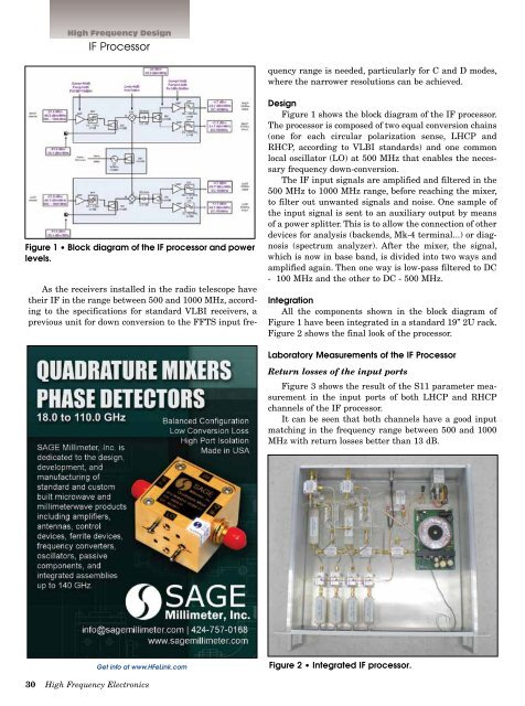
Integration<br />
All the components shown in the block diagram <strong>of</strong><br />
Figure 1 have been integrated in a standard 19’’ 2U rack.<br />
Figure 2 shows the final look <strong>of</strong> the processor.<br />
Laboratory Measurements <strong>of</strong> the IF Processor<br />
Return losses <strong>of</strong> the input ports<br />
Figure 3 shows the result <strong>of</strong> the S11 parameter measurement<br />
in the input ports <strong>of</strong> both LHCP and RHCP<br />
channels <strong>of</strong> the IF processor.<br />
It can be seen that both channels have a good input<br />
matching in the frequency range between 500 and 1000<br />
MHz with return losses better than 13 dB.<br />
Get info at www.HFeLink.com<br />
Figure 2 • Integrated IF processor.<br />
30 <strong>High</strong> <strong>Frequency</strong> <strong>Electronics</strong>


