PROFIBUS DP-Master
PROFIBUS DP-Master
PROFIBUS DP-Master

You also want an ePaper? Increase the reach of your titles
YUMPU automatically turns print PDFs into web optimized ePapers that Google loves.
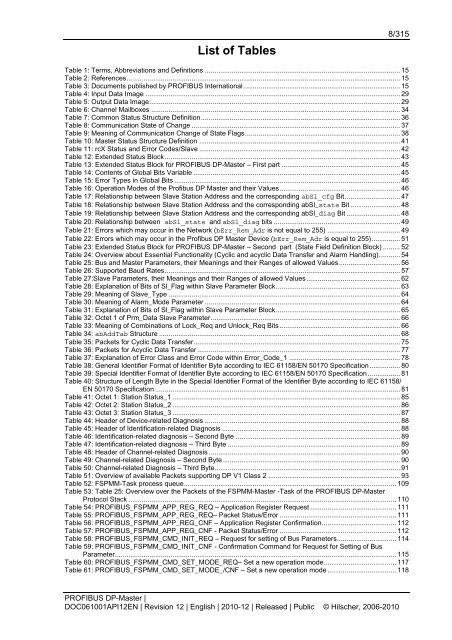
List of Tables<br />
8/315<br />
Table 1: Terms, Abbreviations and Definitions ...................................................................................................... 15<br />
Table 2: References............................................................................................................................................... 15<br />
Table 3: Documents published by <strong>PROFIBUS</strong> International.................................................................................. 15<br />
Table 4: Input Data Image ..................................................................................................................................... 29<br />
Table 5: Output Data Image................................................................................................................................... 29<br />
Table 6: Channel Mailboxes .................................................................................................................................. 34<br />
Table 7: Common Status Structure Definition........................................................................................................ 36<br />
Table 8: Communication State of Change ............................................................................................................. 37<br />
Table 9: Meaning of Communication Change of State Flags................................................................................. 38<br />
Table 10: <strong>Master</strong> Status Structure Definition ......................................................................................................... 41<br />
Table 11: rcX Status and Error Codes/Slave ......................................................................................................... 42<br />
Table 12: Extended Status Block........................................................................................................................... 43<br />
Table 13: Extended Status Block for <strong>PROFIBUS</strong> <strong>DP</strong>-<strong>Master</strong> – First part .............................................................. 45<br />
Table 14: Contents of Global Bits Variable ............................................................................................................ 45<br />
Table 15: Error Types in Global Bits ...................................................................................................................... 46<br />
Table 16: Operation Modes of the Profibus <strong>DP</strong> <strong>Master</strong> and their Values............................................................... 46<br />
Table 17: Relationship between Slave Station Address and the corresponding abSl_cfg Bit............................. 47<br />
Table 18: Relationship between Slave Station Address and the corresponding abSl_state Bit .......................... 48<br />
Table 19: Relationship between Slave Station Address and the corresponding abSl_diag Bit ............................ 48<br />
Table 20: Relationship between abSl_state and abSl_diag bits .................................................................. 49<br />
Table 21: Errors which may occur in the Network (bErr_Rem_Adr is not equal to 255) ...................................... 49<br />
Table 22: Errors which may occur in the Profibus <strong>DP</strong> <strong>Master</strong> Device (bErr_Rem_Adr is equal to 255)............... 51<br />
Table 23: Extended Status Block for <strong>PROFIBUS</strong> <strong>DP</strong>-<strong>Master</strong> – Second part (State Field Definition Block) ......... 52<br />
Table 24: Overview about Essential Functionality (Cyclic and acyclic Data Transfer and Alarm Handling)........... 54<br />
Table 25: Bus and <strong>Master</strong> Parameters, their Meanings and their Ranges of allowed Values................................ 56<br />
Table 26: Supported Baud Rates........................................................................................................................... 57<br />
Table 27:Slave Parameters, their Meanings and their Ranges of allowed Values................................................. 62<br />
Table 28: Explanation of Bits of Sl_Flag within Slave Parameter Block................................................................. 63<br />
Table 29: Meaning of Slave_Type ......................................................................................................................... 64<br />
Table 30: Meaning of Alarm_Mode Parameter ...................................................................................................... 64<br />
Table 31: Explanation of Bits of Sl_Flag within Slave Parameter Block................................................................. 65<br />
Table 32: Octet 1 of Prm_Data Slave Parameter................................................................................................... 66<br />
Table 33: Meaning of Combinations of Lock_Req and Unlock_Req Bits ............................................................... 66<br />
Table 34: abAddTab Structure .............................................................................................................................. 68<br />
Table 35: Packets for Cyclic Data Transfer............................................................................................................ 75<br />
Table 36: Packets for Acyclic Data Transfer .......................................................................................................... 77<br />
Table 37: Explanation of Error Class and Error Code within Error_Code_1 .......................................................... 78<br />
Table 38: General Identifier Format of Identifier Byte according to IEC 61158/EN 50170 Specification ................ 80<br />
Table 39: Special Identifier Format of Identifier Byte according to IEC 61158/EN 50170 Specification................. 81<br />
Table 40: Structure of Length Byte in the Special Identifier Format of the Identifier Byte according to IEC 61158/<br />
EN 50170 Specification ................................................................................................................................ 81<br />
Table 41: Octet 1: Station Status_1 ....................................................................................................................... 85<br />
Table 42: Octet 2: Station Status_2 ....................................................................................................................... 86<br />
Table 43: Octet 3: Station Status_3 ....................................................................................................................... 87<br />
Table 44: Header of Device-related Diagnosis ...................................................................................................... 88<br />
Table 45: Header of Identification-related Diagnosis ............................................................................................. 88<br />
Table 46: Identification-related diagnosis – Second Byte ...................................................................................... 89<br />
Table 47: Identification-related diagnosis – Third Byte .......................................................................................... 89<br />
Table 48: Header of Channel-related Diagnosis .................................................................................................... 90<br />
Table 49: Channel-related Diagnosis – Second Byte............................................................................................. 90<br />
Table 50: Channel-related Diagnosis – Third Byte................................................................................................. 91<br />
Table 51: Overview of available Packets supporting <strong>DP</strong> V1 Class 2 ..................................................................... 93<br />
Table 52: FSPMM-Task process queue............................................................................................................... 109<br />
Table 53: Table 25: Overview over the Packets of the FSPMM-<strong>Master</strong> -Task of the <strong>PROFIBUS</strong> <strong>DP</strong>-<strong>Master</strong><br />
Protocol Stack ............................................................................................................................................ 110<br />
Table 54: <strong>PROFIBUS</strong>_FSPMM_APP_REG_REQ – Application Register Request ............................................. 111<br />
Table 55: <strong>PROFIBUS</strong>_FSPMM_APP_REG_REQ– Packet Status/Error ............................................................. 111<br />
Table 56: <strong>PROFIBUS</strong>_FSPMM_APP_REG_CNF – Application Register Confirmation....................................... 112<br />
Table 57: <strong>PROFIBUS</strong>_FSPMM_APP_REG_CNF - Packet Status/Error ............................................................. 112<br />
Table 58: <strong>PROFIBUS</strong>_FSPMM_CMD_INIT_REQ – Request for setting of Bus Parameters............................... 114<br />
Table 59: <strong>PROFIBUS</strong>_FSPMM_CMD_INIT_CNF - Confirmation Command for Request for Setting of Bus<br />
Parameter................................................................................................................................................... 115<br />
Table 60: <strong>PROFIBUS</strong>_FSPMM_CMD_SET_MODE_REQ– Set a new operation mode...................................... 117<br />
Table 61: <strong>PROFIBUS</strong>_FSPMM_CMD_SET_MODE_/CNF – Set a new operation mode .................................... 118<br />
<strong>PROFIBUS</strong> <strong>DP</strong>-<strong>Master</strong> |<br />
DOC061001API12EN | Revision 12 | English | 2010-12 | Released | Public © Hilscher, 2006-2010