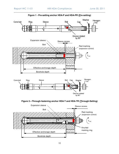
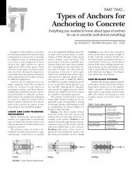
<str<strong>on</strong>g>Report</str<strong>on</strong>g> WC 11-01 <strong>Hilti</strong> <str<strong>on</strong>g>HDA</str<strong>on</strong>g> Compliance June 30, 2011 Figure 1 - Pre-setting anchor <str<strong>on</strong>g>HDA</str<strong>on</strong>g>-P <strong>and</strong> <str<strong>on</strong>g>HDA</str<strong>on</strong>g>-PR (Pre-setting) C o n e b o lt R i n g S l e e v e B o lt C a p W a s h e r H e x a g o n n u t Expansi<strong>on</strong> sleeve Bolt Sleeve recess G ro o v e ro t a t e d b y 9 0 ° Red marking (expansi<strong>on</strong> c<strong>on</strong>trol) T inst Effective anchorage depth Baseplate thickness Borehole depth C o ne b o lt R in g S lee v e B olt C a p W as h er H e x a g o n n ut G r oo v e ro tat ed b y 90 ° Figure 2—Through-fastening anchor <str<strong>on</strong>g>HDA</str<strong>on</strong>g>-T <strong>and</strong> <str<strong>on</strong>g>HDA</str<strong>on</strong>g>-TR (Through-Setting) Expansi<strong>on</strong> sleeve Bolt Sleeve recess Red marking (expansi<strong>on</strong> c<strong>on</strong>trol) T inst Effective anchorage depth Borehole depth Baseplate thickness Knurled marking ring 10
<str<strong>on</strong>g>Report</str<strong>on</strong>g> WC 11-01 <strong>Hilti</strong> <str<strong>on</strong>g>HDA</str<strong>on</strong>g> Compliance June 30, 2011 Design parameter Symbol Units Anchor diameter d 0 Effective min. embedment depth 1,9 Minimum edge distance 7 Minimum anchor spacing Minimum member thickness h ef,min c min s min h min Table 1—<str<strong>on</strong>g>HDA</str<strong>on</strong>g> Design informati<strong>on</strong> mm (in.) Nominal anchor diameter M10 M12 M16 M20 <str<strong>on</strong>g>HDA</str<strong>on</strong>g> <str<strong>on</strong>g>HDA</str<strong>on</strong>g>-R <str<strong>on</strong>g>HDA</str<strong>on</strong>g> <str<strong>on</strong>g>HDA</str<strong>on</strong>g>-R <str<strong>on</strong>g>HDA</str<strong>on</strong>g> <str<strong>on</strong>g>HDA</str<strong>on</strong>g>-R <str<strong>on</strong>g>HDA</str<strong>on</strong>g> 19 21 29 35 (0.75) (0.83) (1.14) (1.38) mm 100 125 190 250 (in.) (3.94) (4.92) (7.48) (9.84) mm 80 100 150 200 (in.) (3-1/8) (4) (5-7/8) (7-7/8) mm 100 125 190 250 (in.) (4) (5) (7-1/2) (9-7/8) mm 170 190 270 350 (in.) (6-3/4) (7-1/2) (10-5/8) (13-3/4) Strength reducti<strong>on</strong> factor for tensi<strong>on</strong>, steel failure modes 2 φ - 0.80 Strength reducti<strong>on</strong> factor for shear, steel failure modes 2 φ - 0.75 Strength reducti<strong>on</strong> factor for c<strong>on</strong>crete breakout, side-face blowout, pullout or φ - 0.75 pryout strength 2 Yield strength of anchor steel f y lb/in 2 92,800 Ultimate strength of anchor steel f ut lb/in 2 116,000 Tensile stress area A se in 2 0.090 0.131 0.243 0.380 Steel strength in tensi<strong>on</strong> N s lb 10,431 15,152 28,236 44,063 Effectiveness factor cracked c<strong>on</strong>crete 3 k - 24 24 24 24 24 24 24 Modificati<strong>on</strong> factor for uncracked 4 c<strong>on</strong>crete Ψ3 - 1.25 1.25 1.25 1.25 1.25 1.25 1.25 Pullout strength cracked c<strong>on</strong>crete, static <strong>and</strong> seismic 5 N p,cr lb 8,992 8,992 11,240 11,240 22,481 22,481 33,721 Steel strength in shear, static <str<strong>on</strong>g>HDA</str<strong>on</strong>g>-P/PR 6 V s lb 5,013 6,070 7,284 8,992 13,556 16,861 20,772 Steel strength in shear, seismic 6 <str<strong>on</strong>g>HDA</str<strong>on</strong>g>-P/PR V s,seismic lb 4,496 5,620 6,519 8,093 12,140 15,062 18,659 Axial stiffness in service load range in cracked / uncracked c<strong>on</strong>crete 8 β 10³ lb/in. 80 / 100 1 Actual h ef for <str<strong>on</strong>g>HDA</str<strong>on</strong>g>-T is given by h ef,min + (t fix,max – t fix) where t fix,max is given in Table 4b <strong>and</strong> t fix is the thickness of the part(s) being fastened. 2 See ACI 349-01, Appendix B, secti<strong>on</strong> B.4.4. For use with the load combinati<strong>on</strong>s of ACI 349-01, secti<strong>on</strong> 9.2. 3 See ACI 349-01 Appendix B, secti<strong>on</strong> B.5.2.2 <strong>and</strong> B.5.2.8. The k factor for the <str<strong>on</strong>g>HDA</str<strong>on</strong>g> Undercut anchor is based <strong>on</strong> testing <strong>and</strong> assessment in accordance with ACI 355.2-01. 4 See ACI 349-01 Appendix B, secti<strong>on</strong> B.5.2.6 <strong>and</strong> B.5.2.8. The value Ψ 3 is calculated to k uncr/k cr = 30/24 = 1.25. The k factors for the <str<strong>on</strong>g>HDA</str<strong>on</strong>g> Undercut anchor are based <strong>on</strong> testing <strong>and</strong> assessment in accordance with ACI 355.2-01. 5 The pullout strength of the anchor in cracked c<strong>on</strong>crete is governed by anchor displacement under c<strong>on</strong>diti<strong>on</strong>s with crack width cycling. In uncracked c<strong>on</strong>crete, pullout does not govern. 6 For <str<strong>on</strong>g>HDA</str<strong>on</strong>g>-T see Table 2. 7 Splitting failure under external load does not govern the resistance of the <str<strong>on</strong>g>HDA</str<strong>on</strong>g>. Therefore, no values for the critical edge distance c cr are provided since this calculati<strong>on</strong> is not required for design. 8 Minimum axial stiffness values, maximum values may be 3 times larger (e.g. due to high strength c<strong>on</strong>crete) 9 To calculate the basic c<strong>on</strong>crete breakout strength V b, l equals h ef . In no cases shall l exceed 8d o. See ACI 349-01 Appendix B, secti<strong>on</strong> B.0 11