HDA Nuclear Report on Testing and Evaluation - Hilti Egypt
HDA Nuclear Report on Testing and Evaluation - Hilti Egypt
HDA Nuclear Report on Testing and Evaluation - Hilti Egypt

You also want an ePaper? Increase the reach of your titles
YUMPU automatically turns print PDFs into web optimized ePapers that Google loves.
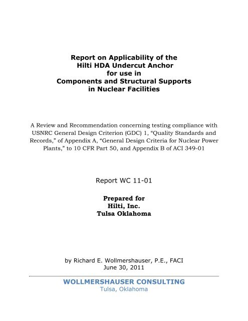
<str<strong>on</strong>g>Report</str<strong>on</strong>g> <strong>on</strong> Applicability of the<br />
<strong>Hilti</strong> <str<strong>on</strong>g>HDA</str<strong>on</strong>g> Undercut Anchor<br />
for use in<br />
Comp<strong>on</strong>ents <strong>and</strong> Structural Supports<br />
in <str<strong>on</strong>g>Nuclear</str<strong>on</strong>g> Facilities<br />
A Review <strong>and</strong> Recommendati<strong>on</strong> c<strong>on</strong>cerning testing compliance with<br />
USNRC General Design Criteri<strong>on</strong> (GDC) 1, “Quality St<strong>and</strong>ards <strong>and</strong><br />
Records,” of Appendix A, “General Design Criteria for <str<strong>on</strong>g>Nuclear</str<strong>on</strong>g> Power<br />
Plants,” to 10 CFR Part 50, <strong>and</strong> Appendix B of ACI 349-01<br />
<str<strong>on</strong>g>Report</str<strong>on</strong>g> WC 11-01<br />
Prepared for<br />
<strong>Hilti</strong>, Inc.<br />
Tulsa Oklahoma<br />
by Richard E. Wollmershauser, P.E., FACI<br />
June 30, 2011<br />
WOLLMERSHAUSER CONSULTING<br />
Tulsa, Oklahoma
<str<strong>on</strong>g>Report</str<strong>on</strong>g> WC 11-01 <strong>Hilti</strong> <str<strong>on</strong>g>HDA</str<strong>on</strong>g> Compliance June 30, 2011<br />
Table of C<strong>on</strong>tents<br />
1. Purpose <strong>and</strong> Scope.……………………………………………………………1<br />
2. Qualificati<strong>on</strong> <strong>Testing</strong> Program..……………………………………………2<br />
3. <strong>Testing</strong> Differences am<strong>on</strong>g ICC-ES AC193, ACI 355.2-01, <strong>and</strong><br />
ACI 349-01 Requirements <strong>and</strong> Resoluti<strong>on</strong> of those Differences…3<br />
4. C<strong>on</strong>clusi<strong>on</strong>s <strong>and</strong> Recommendati<strong>on</strong>s………………………………………7<br />
5. References…………………………………………………………………………8<br />
6. Appendix A………………………………………………………………………9<br />
ii
<str<strong>on</strong>g>Report</str<strong>on</strong>g> WC 11-01 <strong>Hilti</strong> <str<strong>on</strong>g>HDA</str<strong>on</strong>g> Compliance June 30, 2011<br />
1. Purpose <strong>and</strong> Scope<br />
<strong>Hilti</strong> has developed an undercut anchor known as the <str<strong>on</strong>g>HDA</str<strong>on</strong>g> Heavy Duty<br />
Undercut Anchor System. The purpose of this document is to evaluate the<br />
qualificati<strong>on</strong> testing performed <strong>on</strong> the <strong>Hilti</strong> <str<strong>on</strong>g>HDA</str<strong>on</strong>g> Heavy Duty Anchor System<br />
<strong>and</strong> determine whether it is in compliance with the requirements of ACI 355.2-<br />
01 <strong>and</strong> ACI 349-01 as recognized by the United States <str<strong>on</strong>g>Nuclear</str<strong>on</strong>g> Regulatory<br />
Commissi<strong>on</strong> in USNRC Regulatory Guide 1.199.<br />
A design guide for use of the <str<strong>on</strong>g>HDA</str<strong>on</strong>g> anchor system under ACI 349-01 <strong>and</strong><br />
USNRC Directive 1.199 is given in Appendix A (supplied by <strong>Hilti</strong>, Inc.). All data<br />
in Appendix A meets the requirements of these two documents.<br />
1
<str<strong>on</strong>g>Report</str<strong>on</strong>g> WC 11-01 <strong>Hilti</strong> <str<strong>on</strong>g>HDA</str<strong>on</strong>g> Compliance June 30, 2011<br />
2. Qualificati<strong>on</strong> <strong>Testing</strong> Program<br />
2.1 <strong>Testing</strong> was ordered by <strong>Hilti</strong> <strong>on</strong> May 11, 2002 <strong>and</strong> c<strong>on</strong>ducted under the<br />
guidance of Prof. Dr.-ing Rolf Eligehausen of the University of Stuttgart,<br />
Germany in 2002 <strong>and</strong> 2003 at the Institut Für Werkstoffe Im Bauwesen <strong>and</strong><br />
other testing laboratories. <strong>Testing</strong> was performed according to AC193.<br />
2.2 AC193 issued by the ICC Evaluati<strong>on</strong> Service references ACI 355.2 as the<br />
base document for the testing <strong>and</strong> evaluati<strong>on</strong> protocol, adding additi<strong>on</strong>al ICC-<br />
ES specific requirements as well as modificati<strong>on</strong>s to specific testing <strong>and</strong><br />
evaluati<strong>on</strong> requirements. Those differences <strong>and</strong> the resulting anchor<br />
qualificati<strong>on</strong> <strong>and</strong> <str<strong>on</strong>g>HDA</str<strong>on</strong>g> design data will be the focus of this document.<br />
2.3 For anchors to be used in facilities under the purview of the USNRC,<br />
USNRC requirements must be met. Those requirements are summarized in<br />
Regulatory guide 1.199. In that guide, ACI 349-01 Appendix B Anchoring to<br />
C<strong>on</strong>crete c<strong>on</strong>tains the basic design requirements for anchoring, <strong>and</strong> ACI 355.2<br />
is an acceptable testing guide for mechanical anchors.<br />
2.4 All submitted testing of the <str<strong>on</strong>g>HDA</str<strong>on</strong>g> Anchor System was performed in a<br />
satisfactory manner <strong>and</strong> submitted to ICC-ES for their review. After<br />
c<strong>on</strong>siderable review, an evaluati<strong>on</strong> service report (ESR) was issued, ESR 1546,<br />
which recognized compliance with AC193. The ESR specified the appropriate<br />
design data <strong>and</strong> parameters for use with ACI 318-02, Appendix D.<br />
2.5 Because of differences in evaluati<strong>on</strong> requirements between ACI 355.2-01<br />
<strong>and</strong> actual testing performed under AC193, this report has been prepared to<br />
explain <strong>and</strong> comment <strong>on</strong> those differences.<br />
2
<str<strong>on</strong>g>Report</str<strong>on</strong>g> WC 11-01 <strong>Hilti</strong> <str<strong>on</strong>g>HDA</str<strong>on</strong>g> Compliance June 30, 2011<br />
3. <strong>Testing</strong> Differences am<strong>on</strong>g ICC-ES AC193, ACI 355.2-01,<br />
<strong>and</strong> ACI 349-01 Requirements <strong>and</strong> Resoluti<strong>on</strong> of those<br />
Differences<br />
3.1 <strong>Testing</strong> to be performed or witnessed by an accredited<br />
laboratory.<br />
ACI 355.2-01 in Secti<strong>on</strong> 12.1states that,<br />
“The testing <strong>and</strong> evaluati<strong>on</strong> of anchors under ACI 355.2-01 shall be<br />
performed or witnessed by an independent testing <strong>and</strong> evaluati<strong>on</strong><br />
agency listed by a recognized accreditati<strong>on</strong> service c<strong>on</strong>forming to the<br />
requirements of ISO Guides 25 <strong>and</strong> 58. In additi<strong>on</strong> to these<br />
st<strong>and</strong>ards, listing of the <strong>Testing</strong> <strong>and</strong> Evaluati<strong>on</strong> Agency shall be<br />
predicated <strong>on</strong> the documented experience in the testing <strong>and</strong> evaluati<strong>on</strong><br />
of anchors according to ASTM E 488 including dem<strong>on</strong>strated<br />
competence to perform the tests described in ACI 355.2-01.”<br />
ACI 349-01 states in Secti<strong>on</strong> B3.3 that,<br />
“Post-installed structural anchors shall be tested before use to verify<br />
that they are capable of sustaining their design strength in cracked<br />
c<strong>on</strong>crete under seismic loads. These verificati<strong>on</strong> tests shall be<br />
c<strong>on</strong>ducted by an independent testing agency <strong>and</strong> shall be certified<br />
by a professi<strong>on</strong>al engineer with full descripti<strong>on</strong> <strong>and</strong> details of the<br />
testing programs, procedures, results, <strong>and</strong> c<strong>on</strong>clusi<strong>on</strong>s.”<br />
Test data obtained for the <str<strong>on</strong>g>HDA</str<strong>on</strong>g> evaluati<strong>on</strong> according to Annex 1, Secti<strong>on</strong> 5.3, of<br />
AC193, was required to be performed in a laboratory accredited under the<br />
requirements of ISO/IEC 17025. Further, a listing, by an accredited listing<br />
agency, of the testing <strong>and</strong> evaluati<strong>on</strong> laboratory was required to be based <strong>on</strong><br />
the documented experience in the testing <strong>and</strong> evaluati<strong>on</strong> of anchors according<br />
to ASTM E 488.<br />
Resoluti<strong>on</strong>: <strong>Testing</strong> was performed primarily by the Institut Für Werkstoffe Im<br />
Bauwesen. Other laboratories were also used as given in the following list,<br />
taken from the evaluati<strong>on</strong> report prepared by Prof. Eligehausen. All of the listed<br />
laboratories were accredited by the Internati<strong>on</strong>al Laboratory Accreditati<strong>on</strong><br />
Cooperati<strong>on</strong> (ILAC) under ISO/IEC 17025. IAS, the laboratory <strong>and</strong> testing<br />
accrediting body of the ICC, is also a member of ILAC. The European<br />
accreditati<strong>on</strong> of these testing laboratories was accepted as being competent in<br />
3
<str<strong>on</strong>g>Report</str<strong>on</strong>g> WC 11-01 <strong>Hilti</strong> <str<strong>on</strong>g>HDA</str<strong>on</strong>g> Compliance June 30, 2011<br />
the testing of anchor systems. IWB <strong>and</strong> CSTB were accredited in direct audits<br />
by IAS.<br />
Table 1. <strong>Testing</strong> laboratories used for <str<strong>on</strong>g>HDA</str<strong>on</strong>g> testing<br />
1. CSTB: Centre Scientific et Technique du Batiment, Marne-la-<br />
Vallee, France (accredited by COFRAC (full ILAC-member)<br />
2. IWB: Institut für Werkstoffe im Bauwesen der Universität<br />
Stuttgart, Germany (accredited by ICC ES, IAS, <strong>and</strong> DAR (full ILACmember))<br />
3. HTL: Bautechnische Versushsanstalt an der HTL Rankweil,<br />
Austria (accredited by BMWA (full ILAC-member))<br />
4. F: Forschungs- und Materialprüfungsanstalt Baden Württemberg<br />
Otto-Graf-Institut, Stuttgart, Germany (DIBt-accredited)<br />
5. L: Material Research <strong>and</strong> <strong>Testing</strong> Institute for C<strong>on</strong>structi<strong>on</strong>,<br />
Liepzig, Germany (DIBt-accredited)<br />
6. D: Institut für Bauforschung, Dortmund, Germany<br />
3.2 <strong>Testing</strong> under the directi<strong>on</strong> of a licensed professi<strong>on</strong>al engineer.<br />
ACI 355.2-01 states in Secti<strong>on</strong> 12.2 that, ”The testing shall be witnessed <strong>and</strong><br />
evaluated by a registered engineer employed or retained by the independent<br />
testing <strong>and</strong> evaluati<strong>on</strong> agency.”<br />
Resoluti<strong>on</strong>: <strong>Testing</strong> was overseen by <strong>and</strong> the Evaluati<strong>on</strong> report submittal<br />
prepared by Prof. Dr.-Ing. Rolf Eligehausen of the University of Stuttgart<br />
Institute for Building Materials. (He is now retired.). Prof. Eligehausen is not a<br />
registered engineer because there is no formal engineering registrati<strong>on</strong> system<br />
in Europe. Note that in Europe, licensing of structural engineers is<br />
accomplished through accredited educati<strong>on</strong>al instituti<strong>on</strong>s. Prof. Eligehausen is<br />
accredited for performing structural engineering. His experience in the<br />
technology of fastening to c<strong>on</strong>crete is significant.<br />
Prof. Eligehausen has been c<strong>on</strong>ducting evaluati<strong>on</strong> <strong>and</strong> approval of anchors in<br />
Europe for more than 25 years, initially under DIBt (German) rules, <strong>and</strong> later<br />
under the EOTA (European Organisati<strong>on</strong> for Technical Approvals<br />
(http://www.eota.be) guidelines. He participated in the development of the<br />
criteria for qualificati<strong>on</strong> of anchor systems both in Europe <strong>and</strong> the United<br />
States. As the author or co-author of over 230 papers <strong>and</strong> publicati<strong>on</strong>s in<br />
Europe <strong>and</strong> the U.S. <strong>on</strong> the subject of b<strong>on</strong>d <strong>and</strong> anchorage <strong>and</strong> as a Fellow of<br />
4
<str<strong>on</strong>g>Report</str<strong>on</strong>g> WC 11-01 <strong>Hilti</strong> <str<strong>on</strong>g>HDA</str<strong>on</strong>g> Compliance June 30, 2011<br />
the American C<strong>on</strong>crete Institute, Prof. Eligehausen has established a<br />
reputati<strong>on</strong> <strong>on</strong> both sides of the Atlantic as the pre-eminent expert in the world<br />
<strong>on</strong> anchorage to c<strong>on</strong>crete. In additi<strong>on</strong>, Prof. Eligehausen c<strong>on</strong>ducts his own<br />
structural engineering practice as founder <strong>and</strong> principal of IEA (Ingenieurbüro<br />
Eligehausen und Asmus http://www.i-ea.de).<br />
3.3 Method used to calculate the effectiveness factor, k.<br />
Both ACI 355.2-01 <strong>and</strong> ACI 349-01 require that the k-factor (effectiveness<br />
factor, whose value depends <strong>on</strong> the type of anchor) reported for the anchors be<br />
calculated from the 5% fractile of the test data. ICC-ES AC193 allows the mean<br />
values to be used as an alternative to the 5% fractile, <strong>and</strong> ICC-ES ESR 1546<br />
reports the k-factor calculated from the mean test data.<br />
Resoluti<strong>on</strong>: The original test data used in developing ESR 1546 was evaluated<br />
using both the 5% fractile <strong>and</strong> mean values. There is no difference between the<br />
k-factors using the 5% fractile of the test data <strong>and</strong> the mean test data. The<br />
published values in ESR 1546 were based <strong>on</strong> the mean values. The values used<br />
in Appendix A—Design informati<strong>on</strong> for the <strong>Hilti</strong> Undercut Anchor <str<strong>on</strong>g>HDA</str<strong>on</strong>g> in<br />
Accordance with ACI 349-01 Appendix B were based <strong>on</strong> 5% fractile<br />
calculati<strong>on</strong>s. They are the same.<br />
Table 2—Comparis<strong>on</strong> of effectiveness factors, k.<br />
Uncracked c<strong>on</strong>crete Cracked c<strong>on</strong>crete<br />
Based <strong>on</strong> 5% fractile calculati<strong>on</strong> 30 24<br />
Based <strong>on</strong> mean test data calculati<strong>on</strong> — 24<br />
3.4 Calculati<strong>on</strong> of c<strong>on</strong>crete compressive strengths.<br />
Since the testing was performed in a German test laboratory, the c<strong>on</strong>crete<br />
compressive strengths were determined according to European st<strong>and</strong>ards<br />
using the 150 mm cube strength rather than the 150 mm x 300 mm cylinder<br />
strengths used typically in the United States.<br />
Resoluti<strong>on</strong>: In the evaluati<strong>on</strong> performed for ESR 1546, these cube strengths<br />
were c<strong>on</strong>verted from SI units to in.-lb units using st<strong>and</strong>ard c<strong>on</strong>versi<strong>on</strong><br />
equati<strong>on</strong>s that have been universally accepted in both the European <strong>and</strong><br />
United States c<strong>on</strong>crete industry. They are as follows.<br />
fc,cyl = fc,cube 150/1.25 for low strength c<strong>on</strong>crete fc,cyl < 50 N/mm 2<br />
fc,cyl = fc,cube 150/1.05 for low strength c<strong>on</strong>crete fc,cyl ≥ 50 N/mm 2<br />
5
<str<strong>on</strong>g>Report</str<strong>on</strong>g> WC 11-01 <strong>Hilti</strong> <str<strong>on</strong>g>HDA</str<strong>on</strong>g> Compliance June 30, 2011<br />
3.5 Questi<strong>on</strong> <strong>on</strong> measurement of ductility of the <str<strong>on</strong>g>HDA</str<strong>on</strong>g> anchor steel.<br />
ACI 355.2-01 does not c<strong>on</strong>tain criteria for establishing the ductility of<br />
mechanical anchor steel. ACI 318-02 (Secti<strong>on</strong> D.1 Definiti<strong>on</strong>s) define it as,<br />
“ductile steel element—An element with a tensile test el<strong>on</strong>gati<strong>on</strong> of at least 14<br />
percent <strong>and</strong> reducti<strong>on</strong> in area of at least 30 percent. A steel element meeting<br />
the requirements of ASTM A 307 shall be c<strong>on</strong>sidered ductile.”<br />
Resoluti<strong>on</strong>: AC193 has incorporated a method for determinati<strong>on</strong> of anchor<br />
steel element ductility.<br />
4.3.9 Classificati<strong>on</strong> of Anchor Steel as Ductile or Brittle—El<strong>on</strong>gati<strong>on</strong> <strong>and</strong> reducti<strong>on</strong><br />
of area shall be determined according to a recognized st<strong>and</strong>ard <strong>and</strong> reported <strong>on</strong> the<br />
data sheet (Chapter 11). If the el<strong>on</strong>gati<strong>on</strong> is at least 14 percent <strong>and</strong> the reducti<strong>on</strong> of<br />
area is at least 30 percent, the anchor shall be c<strong>on</strong>sidered to meet the ductile steel<br />
requirements. If the ductility <strong>and</strong> reducti<strong>on</strong> of area cannot be determined, the anchor<br />
shall be reported as brittle in the report.<br />
While ACI 355.2-01 does not specify how ductility shall be determined or<br />
performed, testing of steel elements in the USA typically uses ASTM F 606. As<br />
explained by Eligehausen <strong>and</strong> Asmus in the submittal to ICC-ES, the<br />
el<strong>on</strong>gati<strong>on</strong> is measured over a gage length of 4d. In Europe, where the ductility<br />
testing was performed <strong>on</strong> the <str<strong>on</strong>g>HDA</str<strong>on</strong>g> anchor, the el<strong>on</strong>gati<strong>on</strong> is measured<br />
according to EN 10002 <strong>and</strong> ISO 898, using a gage length of 5d. The el<strong>on</strong>gati<strong>on</strong><br />
is measured after rupture of the steel, <strong>and</strong> is referred to as rupture el<strong>on</strong>gati<strong>on</strong>.<br />
Since the measured el<strong>on</strong>gati<strong>on</strong> c<strong>on</strong>tains a small plastic deformati<strong>on</strong> due to<br />
c<strong>on</strong>tracti<strong>on</strong> of the steel after passing the peak load, the c<strong>on</strong>tracti<strong>on</strong> is limited to<br />
a small length. Under ISO 898, a minimum 12% el<strong>on</strong>gati<strong>on</strong> is required with a<br />
gage length if 5d, which related to a 14% el<strong>on</strong>gati<strong>on</strong> under ASTM F 606.<br />
El<strong>on</strong>gati<strong>on</strong> testing performed in accordance with EN 10002 <strong>and</strong> ISO 898 was<br />
submitted, reviewed, <strong>and</strong> accepted by ICC-ES. The data dem<strong>on</strong>strated the<br />
actual rupture el<strong>on</strong>gati<strong>on</strong> was even greater than required as a ductile steel<br />
element.<br />
Therefore the el<strong>on</strong>gati<strong>on</strong> requirement is met. Similarly, the measured<br />
reducti<strong>on</strong> of area was greater than 30%. In c<strong>on</strong>clusi<strong>on</strong>, the <str<strong>on</strong>g>HDA</str<strong>on</strong>g> anchor steel<br />
meets the AC193 requirement of “ductility”.<br />
6
<str<strong>on</strong>g>Report</str<strong>on</strong>g> WC 11-01 <strong>Hilti</strong> <str<strong>on</strong>g>HDA</str<strong>on</strong>g> Compliance June 30, 2011<br />
4. C<strong>on</strong>clusi<strong>on</strong>s <strong>and</strong> Recommendati<strong>on</strong>s<br />
4.1 The areas where ACI 355.2-01 <strong>and</strong> ACI 349-01 differ from AC193 are<br />
discussed above. Evidence is provided dem<strong>on</strong>strating that, while the<br />
language of the st<strong>and</strong>ards varies, the actual testing <strong>and</strong> evaluati<strong>on</strong> neverthe-less<br />
met their intent <strong>and</strong> requirements. The remainder of ACI 355.2-01<br />
<strong>and</strong> ACI 349-01 does not c<strong>on</strong>tain any other requirements that are<br />
functi<strong>on</strong>ally different from AC193. Therefore after review of all pertinent<br />
data <strong>and</strong> evaluati<strong>on</strong>s, it is my opini<strong>on</strong> that the testing performed <strong>on</strong> the <strong>Hilti</strong><br />
<str<strong>on</strong>g>HDA</str<strong>on</strong>g> ANCHOR system meets the intent <strong>and</strong> requirements of ACI 355.2-01<br />
<strong>and</strong> ACI 349-01.<br />
The evaluati<strong>on</strong>s performed <strong>and</strong> the data as presented in Design<br />
informati<strong>on</strong> for the <strong>Hilti</strong> Undercut Anchor <str<strong>on</strong>g>HDA</str<strong>on</strong>g> in Accordance with ACI<br />
349-01 Appendix B attached to this report as Appendix A are accurate <strong>and</strong><br />
comply with the intent <strong>and</strong> requirements of ACI 355.2-01, ACI 349-01, <strong>and</strong><br />
USNRC Regulatory Guide 1.199.<br />
Richard E. Wollmershauser, P.E., FACI<br />
June 30, 2011<br />
Tulsa, Oklahoma<br />
7
<str<strong>on</strong>g>Report</str<strong>on</strong>g> WC 11-01 <strong>Hilti</strong> <str<strong>on</strong>g>HDA</str<strong>on</strong>g> Compliance June 30, 2011<br />
5. References<br />
1. ACI 349-01 Code Requirements for <str<strong>on</strong>g>Nuclear</str<strong>on</strong>g> Safety Related C<strong>on</strong>crete<br />
Structures; Appendix B, Anchoring to C<strong>on</strong>crete; American C<strong>on</strong>crete<br />
Institute, Farmingt<strong>on</strong> Hills, MI.<br />
2. ACI 355.2-01 Evaluating the Performance of Post-Installed Mechanical<br />
Anchors in C<strong>on</strong>crete; American C<strong>on</strong>crete Institute; Farmingt<strong>on</strong> Hills, MI.<br />
3. ASTM E 488-96 (Reapproved 2003), St<strong>and</strong>ard Test Methods for Anchors<br />
in C<strong>on</strong>crete <strong>and</strong> Mas<strong>on</strong>ry Elements; American Society for <strong>Testing</strong> <strong>and</strong><br />
Materials; West C<strong>on</strong>shohocken, PA<br />
4. ASTM F 606-02, St<strong>and</strong>ard Test Methods for Determining the Mechanical<br />
Properties of Externally <strong>and</strong> Internally Threaded Fasteners, Washers,<br />
Direct Tensi<strong>on</strong> Indicators, <strong>and</strong> Rivets; American Society for <strong>Testing</strong> <strong>and</strong><br />
Materials; West C<strong>on</strong>shohocken, PA.<br />
5. ICC-Evaluati<strong>on</strong> Service Inc., Whittier, CA; Acceptance Criteria for<br />
Mechanical Anchors in C<strong>on</strong>crete Elements (AC193); January, 2003.<br />
6. EN 10002-01:2001; Tensile testing of metallic materials; Internati<strong>on</strong>al<br />
St<strong>and</strong>ards Organizati<strong>on</strong>; September 2001.<br />
7. ISO/IEC 17025; General Requirements for the Competence of <strong>Testing</strong> <strong>and</strong><br />
Calibrati<strong>on</strong> Laboratories; Internati<strong>on</strong>al St<strong>and</strong>ards Organizati<strong>on</strong>;<br />
December 1999.<br />
8. ISO 898, Mechanical Properties of Fasteners made of Carb<strong>on</strong> Steel <strong>and</strong>Alloy<br />
Steel – Part 1: Bolts, Screws <strong>and</strong> Studs with Specified Property Classes – Coarse<br />
Thread <strong>and</strong> Fine Pitch Thread; Internati<strong>on</strong>al St<strong>and</strong>ards Organizati<strong>on</strong>;<br />
August 1999;<br />
9. ICC-ES Evaluati<strong>on</strong> Service <str<strong>on</strong>g>Report</str<strong>on</strong>g> ESR 1546, <strong>Hilti</strong> <str<strong>on</strong>g>HDA</str<strong>on</strong>g> Carb<strong>on</strong> Steel <strong>and</strong><br />
Stainless Steel Undercut Anchors for Cracked <strong>and</strong> Uncracked C<strong>on</strong>crete,<br />
issued August 2004.<br />
10. U.S. <str<strong>on</strong>g>Nuclear</str<strong>on</strong>g> Regulatory Commissi<strong>on</strong>, Washingt<strong>on</strong>, DC: Regulatory Guide<br />
1.199, Anchoring Comp<strong>on</strong>ents <strong>and</strong> Structural Supports in C<strong>on</strong>crete;<br />
November 2003.<br />
11. <strong>Hilti</strong>, Inc., Tulsa, OK: Design Informati<strong>on</strong> for the <strong>Hilti</strong> Undercut Anchor<br />
<str<strong>on</strong>g>HDA</str<strong>on</strong>g> in Accordance with ACI 349-01 Appendix B, June 2011.<br />
8
<str<strong>on</strong>g>Report</str<strong>on</strong>g> WC 11-01 <strong>Hilti</strong> <str<strong>on</strong>g>HDA</str<strong>on</strong>g> Compliance June 30, 2011<br />
Appendix A<br />
(Supplied by <strong>Hilti</strong>, Inc, Tulsa, Oklahoma)<br />
Design informati<strong>on</strong> for the <strong>Hilti</strong> Undercut Anchor <str<strong>on</strong>g>HDA</str<strong>on</strong>g> in Accordance<br />
with ACI 349-01 Appendix B.<br />
1.0 SCOPE<br />
This document is intended to provide guidance <strong>on</strong> the design of anchorages with <strong>Hilti</strong> Undercut<br />
Anchors <str<strong>on</strong>g>HDA</str<strong>on</strong>g> in accordance with ACI 349-01 Appendix B. Note this design varies from current<br />
general industry practice following ACI 318 Appendix D. It is the resp<strong>on</strong>sibility of the engineer of<br />
record to verify the accuracy <strong>and</strong> suitability of all design calculati<strong>on</strong>s, methodologies, capacities<br />
<strong>and</strong> code compliance. Informati<strong>on</strong> c<strong>on</strong>tained in this document was current as of February 4,<br />
2011, <strong>and</strong> is subject to change. Updates <strong>and</strong> changes may be made based <strong>on</strong> subsequent<br />
testing. If verificati<strong>on</strong> is needed that the data is still current, please c<strong>on</strong>tact <strong>Hilti</strong> Technical<br />
Services at 1-877-749-6337.<br />
2.0 USES<br />
The <strong>Hilti</strong> <str<strong>on</strong>g>HDA</str<strong>on</strong>g> Undercut Anchor is used to resist static, wind, <strong>and</strong> seismic tensi<strong>on</strong> <strong>and</strong> shear<br />
loads in cracked <strong>and</strong> uncracked normal-weight c<strong>on</strong>crete having a specified compressive<br />
strength 2,500 psi ≤ f ′ c ≤ 8,500 psi (17.2 MPa ≤ f ′ c ≤ 58.6 MPa). The values of f ′ c used for<br />
calculati<strong>on</strong>s in this guide shall not exceed 8000 psi (55.2 MPa).<br />
3.0 INSTALLATION<br />
Installati<strong>on</strong> shall be in accordance with <strong>Hilti</strong>’s printed installati<strong>on</strong> instructi<strong>on</strong>s as included in the<br />
anchor packaging.<br />
4.0 DESIGN<br />
The design shall be in accordance with this document <strong>and</strong> ACI 349-01 Appendix B. See Figure<br />
3 for a worked example for static tensi<strong>on</strong> loading.<br />
9
<str<strong>on</strong>g>Report</str<strong>on</strong>g> WC 11-01 <strong>Hilti</strong> <str<strong>on</strong>g>HDA</str<strong>on</strong>g> Compliance June 30, 2011<br />
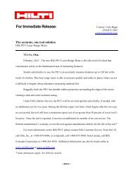
Figure 1 - Pre-setting anchor <str<strong>on</strong>g>HDA</str<strong>on</strong>g>-P <strong>and</strong> <str<strong>on</strong>g>HDA</str<strong>on</strong>g>-PR (Pre-setting)<br />
C o n e b o lt R i n g S l e e v e B o lt<br />
C a p<br />
W a s h e r<br />
H e x a g o n<br />
n u t<br />
Expansi<strong>on</strong> sleeve<br />
Bolt<br />
Sleeve recess<br />
G ro o v e ro t a t e d<br />
b y 9 0 °<br />
Red marking<br />
(expansi<strong>on</strong> c<strong>on</strong>trol)<br />
T inst<br />
Effective anchorage depth<br />
Baseplate<br />
thickness<br />
Borehole depth<br />
C o ne b o lt R in g S lee v e B olt<br />
C a p<br />
W as h er<br />
H e x a g o n<br />
n ut<br />
G r oo v e ro tat ed<br />
b y 90 °<br />
Figure 2—Through-fastening anchor <str<strong>on</strong>g>HDA</str<strong>on</strong>g>-T <strong>and</strong> <str<strong>on</strong>g>HDA</str<strong>on</strong>g>-TR (Through-Setting)<br />
Expansi<strong>on</strong> sleeve<br />
Bolt<br />
Sleeve recess<br />
Red marking<br />
(expansi<strong>on</strong> c<strong>on</strong>trol)<br />
T inst<br />
Effective anchorage depth<br />
Borehole depth<br />
Baseplate<br />
thickness<br />
Knurled<br />
marking ring<br />
10
<str<strong>on</strong>g>Report</str<strong>on</strong>g> WC 11-01 <strong>Hilti</strong> <str<strong>on</strong>g>HDA</str<strong>on</strong>g> Compliance June 30, 2011<br />
Design parameter Symbol Units<br />
Anchor diameter d 0<br />
Effective min. embedment depth 1,9<br />
Minimum edge distance 7<br />
Minimum anchor spacing<br />
Minimum member thickness<br />
h ef,min<br />
c min<br />
s min<br />
h min<br />
Table 1—<str<strong>on</strong>g>HDA</str<strong>on</strong>g> Design informati<strong>on</strong><br />
mm<br />
(in.)<br />
Nominal anchor diameter<br />
M10 M12 M16 M20<br />
<str<strong>on</strong>g>HDA</str<strong>on</strong>g> <str<strong>on</strong>g>HDA</str<strong>on</strong>g>-R <str<strong>on</strong>g>HDA</str<strong>on</strong>g> <str<strong>on</strong>g>HDA</str<strong>on</strong>g>-R <str<strong>on</strong>g>HDA</str<strong>on</strong>g> <str<strong>on</strong>g>HDA</str<strong>on</strong>g>-R <str<strong>on</strong>g>HDA</str<strong>on</strong>g><br />
19 21 29 35<br />
(0.75) (0.83) (1.14) (1.38)<br />
mm 100 125 190 250<br />
(in.) (3.94) (4.92) (7.48) (9.84)<br />
mm 80 100 150 200<br />
(in.) (3-1/8) (4) (5-7/8) (7-7/8)<br />
mm 100 125 190 250<br />
(in.) (4) (5) (7-1/2) (9-7/8)<br />
mm 170 190 270 350<br />
(in.) (6-3/4) (7-1/2) (10-5/8) (13-3/4)<br />
Strength reducti<strong>on</strong> factor for tensi<strong>on</strong>,<br />
steel failure modes 2 φ - 0.80<br />
Strength reducti<strong>on</strong> factor for shear,<br />
steel failure modes 2 φ - 0.75<br />
Strength reducti<strong>on</strong> factor for c<strong>on</strong>crete<br />
breakout, side-face blowout, pullout or φ - 0.75<br />
pryout strength 2<br />
Yield strength of anchor steel f y lb/in 2 92,800<br />
Ultimate strength of anchor steel f ut lb/in 2 116,000<br />
Tensile stress area A se in 2 0.090 0.131 0.243 0.380<br />
Steel strength in tensi<strong>on</strong> N s lb 10,431 15,152 28,236 44,063<br />
Effectiveness factor cracked c<strong>on</strong>crete 3 k - 24 24 24 24 24 24 24<br />
Modificati<strong>on</strong> factor for uncracked<br />
4<br />
c<strong>on</strong>crete<br />
Ψ3 - 1.25 1.25 1.25 1.25 1.25 1.25 1.25<br />
Pullout strength cracked c<strong>on</strong>crete,<br />
static <strong>and</strong> seismic 5 N p,cr lb 8,992 8,992 11,240 11,240 22,481 22,481 33,721<br />
Steel strength in shear, static<br />
<str<strong>on</strong>g>HDA</str<strong>on</strong>g>-P/PR 6 V s lb 5,013 6,070 7,284 8,992 13,556 16,861 20,772<br />
Steel strength in shear, seismic 6<br />
<str<strong>on</strong>g>HDA</str<strong>on</strong>g>-P/PR<br />
V s,seismic lb 4,496 5,620 6,519 8,093 12,140 15,062 18,659<br />
Axial stiffness in service load range in<br />
cracked / uncracked c<strong>on</strong>crete 8 β 10³ lb/in. 80 / 100<br />
1 Actual h ef for <str<strong>on</strong>g>HDA</str<strong>on</strong>g>-T is given by h ef,min + (t fix,max – t fix) where t fix,max is given in Table 4b <strong>and</strong> t fix is the thickness of the part(s) being fastened.<br />
2 See ACI 349-01, Appendix B, secti<strong>on</strong> B.4.4. For use with the load combinati<strong>on</strong>s of ACI 349-01, secti<strong>on</strong> 9.2.<br />
3 See ACI 349-01 Appendix B, secti<strong>on</strong> B.5.2.2 <strong>and</strong> B.5.2.8. The k factor for the <str<strong>on</strong>g>HDA</str<strong>on</strong>g> Undercut anchor is based <strong>on</strong> testing <strong>and</strong> assessment in<br />
accordance with ACI 355.2-01.<br />
4 See ACI 349-01 Appendix B, secti<strong>on</strong> B.5.2.6 <strong>and</strong> B.5.2.8. The value Ψ 3 is calculated to k uncr/k cr = 30/24 = 1.25. The k factors for the <str<strong>on</strong>g>HDA</str<strong>on</strong>g><br />
Undercut anchor are based <strong>on</strong> testing <strong>and</strong> assessment in accordance with ACI 355.2-01.<br />
5 The pullout strength of the anchor in cracked c<strong>on</strong>crete is governed by anchor displacement under c<strong>on</strong>diti<strong>on</strong>s with crack width cycling. In<br />
uncracked c<strong>on</strong>crete, pullout does not govern.<br />
6 For <str<strong>on</strong>g>HDA</str<strong>on</strong>g>-T see Table 2.<br />
7 Splitting failure under external load does not govern the resistance of the <str<strong>on</strong>g>HDA</str<strong>on</strong>g>. Therefore, no values for the critical edge distance c cr are<br />
provided since this calculati<strong>on</strong> is not required for design.<br />
8 Minimum axial stiffness values, maximum values may be 3 times larger (e.g. due to high strength c<strong>on</strong>crete)<br />
9 To calculate the basic c<strong>on</strong>crete breakout strength V b, l equals h ef . In no cases shall l exceed 8d o. See ACI 349-01 Appendix B, secti<strong>on</strong> B.0<br />
11
<str<strong>on</strong>g>Report</str<strong>on</strong>g> WC 11-01 <strong>Hilti</strong> <str<strong>on</strong>g>HDA</str<strong>on</strong>g> Compliance June 30, 2011<br />
Table 2—Design informati<strong>on</strong> - Steel strength in shear, <str<strong>on</strong>g>HDA</str<strong>on</strong>g>-T <strong>and</strong> <str<strong>on</strong>g>HDA</str<strong>on</strong>g>-TR<br />
Anchor Designati<strong>on</strong><br />
Thickness of base plate(s)<br />
t fix<br />
Steel Strength in<br />
Shear, Static<br />
V s<br />
Steel Strength in<br />
Shear, Seismic<br />
V s,seismic<br />
mm in. lb lb<br />
<str<strong>on</strong>g>HDA</str<strong>on</strong>g>-T 20-M10x100<br />
<str<strong>on</strong>g>HDA</str<strong>on</strong>g>-T 22-M12x125<br />
10 ≤ t fix < 15<br />
3 / 8 ≤ t fix < 5 / 8 13,938 12,589<br />
15 ≤ t fix < 20<br />
5 / 8 ≤ t fix < 13 / 16 15,737 14,163<br />
15 ≤ t fix ≤ 20 5/8 ≤ t fix ≤ 13/16<br />
16,636 15,062<br />
20 ≤ t fix ≤ 50 13/16 ≤ t fix ≤ 2<br />
18,659 16,636<br />
Carb<strong>on</strong> Steel Anchors<br />
<str<strong>on</strong>g>HDA</str<strong>on</strong>g>-T 30-M16x190<br />
20 ≤ t fix ≤ 25 13/16 ≤ t fix ≤ 1<br />
25 ≤ t fix ≤ 30 1 ≤ t fix ≤ 1-3/16<br />
30 ≤ t fix ≤ 35 1-3/16 ≤ t fix ≤ 1-3/8<br />
35 ≤ t fix ≤ 60 1-3/8 ≤ t fix ≤ 2-3/8<br />
30,574 27,427<br />
34,621 31,248<br />
38,218 34,396<br />
41,365 37,093<br />
25 ≤ t fix ≤ 40 1 ≤ t fix ≤ 1-9/16<br />
45,187 40,690<br />
<str<strong>on</strong>g>HDA</str<strong>on</strong>g>-T 37-M20x250<br />
40 ≤ t fix ≤ 55 1-9/16 ≤ t fix ≤ 2-1/8<br />
50,807 45,636<br />
55 ≤ t fix ≤ 100 2-1/8 ≤ t fix ≤ 4<br />
54,629 49,233<br />
Stainless Steel Anchors<br />
<str<strong>on</strong>g>HDA</str<strong>on</strong>g>-TR 20-M10x100<br />
<str<strong>on</strong>g>HDA</str<strong>on</strong>g>-TR 22-M12x125<br />
<str<strong>on</strong>g>HDA</str<strong>on</strong>g>-TR 30-M16x190<br />
10 ≤ t fix < 15<br />
3 / 8 ≤ t fix < 5 / 8 15,512 13,938<br />
15 ≤ t fix < 20<br />
5 / 8 ≤ t fix < 13 / 16 16,186 14,613<br />
15 ≤ t fix ≤ 20 5/8 ≤ t fix ≤ 13/16<br />
20,233 17,985<br />
20 ≤ t fix ≤ 50 13/16 ≤ t fix ≤ 2<br />
22,256 20,008<br />
20 ≤ t fix ≤ 25 13/16 ≤ t fix ≤ 1<br />
35,745 32,148<br />
25 ≤ t fix ≤ 30 1 ≤ t fix ≤ 1-3/16<br />
37,768 33,946<br />
30 ≤ t fix ≤ 35 1-3/16 ≤ t fix ≤ 1-3/8<br />
39,566 35,520<br />
35 ≤ t fix ≤ 60 1-3/8 ≤ t fix ≤ 2-3/8<br />
40,915 36,869<br />
For pound-inch units: 1 mm = 0.03937 inch, 1 lbf = 4.45 N.<br />
<str<strong>on</strong>g>HDA</str<strong>on</strong>g> M10 to M20 <strong>and</strong><br />
<str<strong>on</strong>g>HDA</str<strong>on</strong>g>-R M10 to M16<br />
Hole diameter in<br />
base plate(s)<br />
Min. thickness of<br />
base plate(s)<br />
Table 3—<str<strong>on</strong>g>HDA</str<strong>on</strong>g> Hole in base plate(s) <strong>and</strong> minimum thickness of base plate(s)<br />
d h<br />
t fix,min<br />
For in-lb units: 1mm = 0.03937 inches<br />
M10 M12 M16 M20<br />
P T P T P T P T<br />
mm 12 21 14 23 18 32 22 40<br />
(in.) (0.47) (0.83) (0.55) (0.91) (0.71) (1.26) (0.87) (1.57)<br />
mm 0 10 0 15 0 20 0 25<br />
(in.) 0 (0.39) 0 (0.59) 0 (0.79) 0 (0.98)<br />
12
<str<strong>on</strong>g>Report</str<strong>on</strong>g> WC 11-01 <strong>Hilti</strong> <str<strong>on</strong>g>HDA</str<strong>on</strong>g> Compliance June 30, 2011<br />
Table 4a—Maximum thickness of base plate(s) <strong>and</strong> minimum thickness of c<strong>on</strong>crete, <str<strong>on</strong>g>HDA</str<strong>on</strong>g>-P <strong>and</strong><br />
<str<strong>on</strong>g>HDA</str<strong>on</strong>g>-PR<br />
Anchor type<br />
<str<strong>on</strong>g>HDA</str<strong>on</strong>g>-P M10<br />
<str<strong>on</strong>g>HDA</str<strong>on</strong>g>-PR M10<br />
<str<strong>on</strong>g>HDA</str<strong>on</strong>g>-P M12<br />
<str<strong>on</strong>g>HDA</str<strong>on</strong>g>-PR M12<br />
<str<strong>on</strong>g>HDA</str<strong>on</strong>g>-P M16<br />
<str<strong>on</strong>g>HDA</str<strong>on</strong>g>-PR M16<br />
<str<strong>on</strong>g>HDA</str<strong>on</strong>g>-P M20<br />
Maximum thickness of<br />
base plate(s)<br />
Minimum thickness of<br />
c<strong>on</strong>crete member<br />
t fix,max<br />
h min<br />
For inch units: 1 mm = 0.03937 inches<br />
mm 20 30 50 40 60 50 100<br />
in. 0.79 1.18 1.97 1.57 2.36 1.97 3.94<br />
mm 180 200 270 350<br />
in. 7.1 7.9 10.6 13.8<br />
Table 4b—Maximum thickness of base plate(s) <strong>and</strong> minimum thickness of c<strong>on</strong>crete, <str<strong>on</strong>g>HDA</str<strong>on</strong>g>-T, <str<strong>on</strong>g>HDA</str<strong>on</strong>g>-<br />
TR, <str<strong>on</strong>g>HDA</str<strong>on</strong>g>-P <strong>and</strong> <str<strong>on</strong>g>HDA</str<strong>on</strong>g>-PR<br />
Anchor type<br />
<str<strong>on</strong>g>HDA</str<strong>on</strong>g>-T M10<br />
<str<strong>on</strong>g>HDA</str<strong>on</strong>g>-TR<br />
M10<br />
<str<strong>on</strong>g>HDA</str<strong>on</strong>g>-T M12<br />
<str<strong>on</strong>g>HDA</str<strong>on</strong>g>-TR M12<br />
<str<strong>on</strong>g>HDA</str<strong>on</strong>g>-T M16<br />
<str<strong>on</strong>g>HDA</str<strong>on</strong>g>-TR M16<br />
<str<strong>on</strong>g>HDA</str<strong>on</strong>g>-T M20<br />
Maximum thickness of<br />
base plate(s)<br />
Minimum thickness of<br />
c<strong>on</strong>crete member 1<br />
t fix,max<br />
h min<br />
mm 20 30 50 40 60 50 100<br />
in. 0.79 1.18 1.97 1.57 2.36 1.97 3.94<br />
mm 200 - t fix 230 - t fix 250 - t fix 310 - t fix 330 - t fix 400 - t fix 450 - t fix<br />
in. 7.9 - t fix 9.1 - t fix 9.8 - t fix 12.2 - t fix<br />
For inch units: 1 mm = 0.03937 inches<br />
1 h min is dependent <strong>on</strong> the actual thickness of base plate(s) t fix<br />
e.g. <str<strong>on</strong>g>HDA</str<strong>on</strong>g>-T 22-M12x125/50 : t fix = 20 mm h min = 250 - 20 = 230 mm<br />
t fix = 50 mm h min = 250 - 50 = 200 mm<br />
13.0 -<br />
t fix<br />
15.7 - t fix 17.7 - t fix<br />
13
<str<strong>on</strong>g>Report</str<strong>on</strong>g> WC 11-01 <strong>Hilti</strong> <str<strong>on</strong>g>HDA</str<strong>on</strong>g> Compliance June 30, 2011<br />
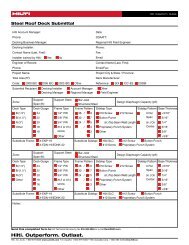
FIGURE 3—<str<strong>on</strong>g>HDA</str<strong>on</strong>g> Sample calculati<strong>on</strong> in accordance with ACI 349-01 Appendix B<br />
Given:<br />
2 <str<strong>on</strong>g>HDA</str<strong>on</strong>g>-P M10 anchors under static<br />
tensi<strong>on</strong> load as shown.<br />
h ef = 3.94 in. (100 mm).<br />
Slab <strong>on</strong> grade, f′ c = 3,000 psi.<br />
No supplementary reinforcing.<br />
Assume cracked c<strong>on</strong>crete<br />
Calculate the design strength in tensi<strong>on</strong><br />
for this c<strong>on</strong>figurati<strong>on</strong>.<br />
A A<br />
AN<br />
h =7”<br />
1.5hef c = 4”<br />
A-A<br />
1.5hef<br />
s = 5”<br />
1.5hef<br />
Calculati<strong>on</strong> per ACI 349-01 Appendix B <strong>and</strong> this document. Code Ref. Guide Ref.<br />
Step 1. Calculate steel strength of anchor in tensi<strong>on</strong> N<br />
s<br />
= nAse<br />
fut<br />
= 2 x10,431=<br />
20, 862lb<br />
B.5.1.2 Table 1<br />
Step 2. Calculate steel capacity φ N s =0 . 80x<br />
20,<br />
862=<br />
16,<br />
689lb<br />
B.4.4 a Table 1<br />
Step 3. Calculate c<strong>on</strong>crete breakout strength of anchor in tensi<strong>on</strong><br />
N<br />
A<br />
N<br />
cbg<br />
=<br />
ANo<br />
ψ ψ ψ N<br />
1 2 3<br />
b<br />
B.5.2.1b -<br />
Step 3a. Check 1.5h = 1.5(3.94) = 5.91in > c 3.0h = 3(3.94) = 11.82 in > s B.5.2.1 Table 1<br />
ef<br />
ef<br />
Step 3b. Check s min = 4 in. < s = 5 in., c min = 3-1/8 in. < c = 4 in., h min = 6-3/4 in. < h = 7 in.<br />
B.8 Table 1<br />
Step 3c. Calculate A No <strong>and</strong> A N for the anchorage: A<br />
[ ][ ]<br />
( )<br />
2<br />
2 2<br />
= 9h = 9 × 3.94 = 139.7 in<br />
No ef<br />
A = ( 1.5 h<br />
N<br />
ef<br />
+ c )(3h ef<br />
+ s ) = 1.5 × (3.94) + 4 3 × (3.94) + 5 = 166.7 in 2<br />
< 2 ⋅ A ∴ ok<br />
No<br />
Step 3d. Calculate ψ :<br />
1<br />
e′<br />
N<br />
=0 ∴<br />
B.5.2.1 Table 1<br />
ψ<br />
1<br />
=1.0 B.5.2.4 Table 1<br />
1.<br />
5<br />
1.<br />
5<br />
Step 3e. Calculate N b: Nb = k f' c hef<br />
= 24x<br />
3,<br />
000 x3.<br />
94 = 10,<br />
280 [lb]<br />
B.5.2.2 Table 1<br />
Step 3f. Calculate modificati<strong>on</strong> factor for edge distance:<br />
4<br />
ψ<br />
2<br />
= 0.7 + 0.3 = 0.90<br />
1.5(3.94)<br />
B.5.2.5 Table 1<br />
Step 3g. For cracked c<strong>on</strong>crete: ψ 3 =1.0 B.5.2.6 Table 1<br />
166.<br />
7<br />
Step 3h. Calculate φN cbg: φ N cbg = 0 . 75x<br />
x1x<br />
0.<br />
90x1x10 , 280 = 8,<br />
280 [lb]<br />
governs<br />
139.<br />
7<br />
B.5.2.1b Table 1<br />
Step 4: Calculate pull out strength: ψ 3N p,cr<br />
ψ 3nN p,cr = N pn = 1.0 x 2 x 8,992 lb = 17,984 lb; ψ 3 = 1.0 (cracked c<strong>on</strong>crete)<br />
φN pn = 0.75 x 17,984 lb = 13,488 lb does not c<strong>on</strong>trol<br />
B.5.3 Table 1<br />
Step 5. Ductility check according to B.3.6.1:<br />
For tensi<strong>on</strong>:<br />
0.85 min[N cbg ; N pn] ≥ A se f uta<br />
=> 0.85 (N cbg) = 0.85 (11,038 lb) = 9,382 lb < 20,862 lb ∴ ductility not met<br />
B.3.6.3 requires an additi<strong>on</strong>al reducti<strong>on</strong> factor of 0.6 for n<strong>on</strong>-ductile anchors<br />
0.6 x N cbg = 0.6 x 8,280 = 4,968 lb<br />
Note: According to B.3.6.2, alternatively the attachment / base plate can be designed to yield at a load<br />
level of 75% of the anchor design strength. In this case, the 0.6 factor would not have to be applied.<br />
B.3.6.1<br />
B.3.6.3 /<br />
B.4.1<br />
Table 1<br />
Rev. 1 2/28/2012 to correct ductility check calculati<strong>on</strong><br />
14