HSL-3 Nuclear Report on Testing and Evaluation - Hilti Egypt
HSL-3 Nuclear Report on Testing and Evaluation - Hilti Egypt
HSL-3 Nuclear Report on Testing and Evaluation - Hilti Egypt

Create successful ePaper yourself
Turn your PDF publications into a flip-book with our unique Google optimized e-Paper software.
<str<strong>on</strong>g>Report</str<strong>on</strong>g> WC 11-02 <strong>Hilti</strong> <str<strong>on</strong>g>HSL</str<strong>on</strong>g>-3 Compliance September 30, 2011<br />
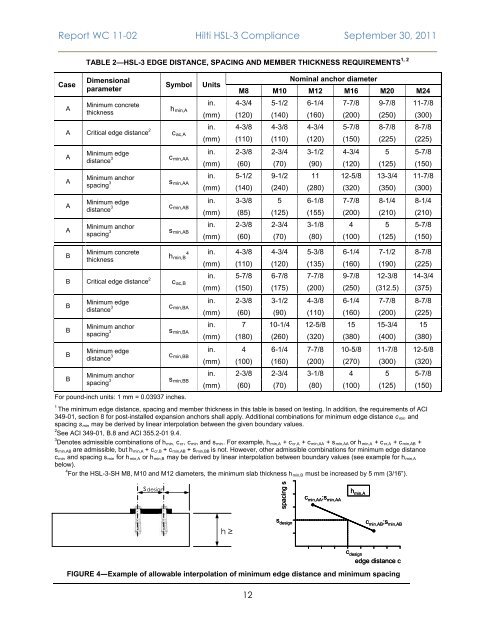
TABLE 2—<str<strong>on</strong>g>HSL</str<strong>on</strong>g>-3 EDGE DISTANCE, SPACING AND MEMBER THICKNESS REQUIREMENTS 1, 2<br />
Case<br />
A<br />
Dimensi<strong>on</strong>al<br />
parameter<br />
Minimum c<strong>on</strong>crete<br />
thickness<br />
Symbol<br />
h min,A<br />
A Critical edge distance 2 c ac,A<br />
A<br />
A<br />
A<br />
A<br />
Minimum edge<br />
distance 3<br />
Minimum anchor<br />
spacing 3<br />
Minimum edge<br />
distance 3<br />
Minimum anchor<br />
spacing 3<br />
c min,AA<br />
s min,AA<br />
c min,AB<br />
s min,AB<br />
Units<br />
Nominal anchor diameter<br />
M8 M10 M12 M16 M20 M24<br />
in. 4-3/4 5-1/2 6-1/4 7-7/8 9-7/8 11-7/8<br />
(mm) (120) (140) (160) (200) (250) (300)<br />
in. 4-3/8 4-3/8 4-3/4 5-7/8 8-7/8 8-7/8<br />
(mm) (110) (110) (120) (150) (225) (225)<br />
in. 2-3/8 2-3/4 3-1/2 4-3/4 5 5-7/8<br />
(mm) (60) (70) (90) (120) (125) (150)<br />
in. 5-1/2 9-1/2 11 12-5/8 13-3/4 11-7/8<br />
(mm) (140) (240) (280) (320) (350) (300)<br />
in. 3-3/8 5 6-1/8 7-7/8 8-1/4 8-1/4<br />
(mm) (85) (125) (155) (200) (210) (210)<br />
in. 2-3/8 2-3/4 3-1/8 4 5 5-7/8<br />
(mm) (60) (70) (80) (100) (125) (150)<br />
B<br />
Minimum c<strong>on</strong>crete<br />
thickness<br />
h min,B<br />
4<br />
B Critical edge distance 2 c ac,B<br />
B<br />
B<br />
B<br />
B<br />
Minimum edge<br />
distance 3<br />
Minimum anchor<br />
spacing 3<br />
Minimum edge<br />
distance 3<br />
Minimum anchor<br />
spacing 3<br />
c min,BA<br />
s min,BA<br />
c min,BB<br />
s min,BB<br />
For pound-inch units: 1 mm = 0.03937 inches.<br />
in. 4-3/8 4-3/4 5-3/8 6-1/4 7-1/2 8-7/8<br />
(mm) (110) (120) (135) (160) (190) (225)<br />
in. 5-7/8 6-7/8 7-7/8 9-7/8 12-3/8 14-3/4<br />
(mm) (150) (175) (200) (250) (312.5) (375)<br />
in. 2-3/8 3-1/2 4-3/8 6-1/4 7-7/8 8-7/8<br />
(mm) (60) (90) (110) (160) (200) (225)<br />
in. 7 10-1/4 12-5/8 15 15-3/4 15<br />
(mm) (180) (260) (320) (380) (400) (380)<br />
in. 4 6-1/4 7-7/8 10-5/8 11-7/8 12-5/8<br />
(mm) (100) (160) (200) (270) (300) (320)<br />
in. 2-3/8 2-3/4 3-1/8 4 5 5-7/8<br />
(mm) (60) (70) (80) (100) (125) (150)<br />
1<br />
The minimum edge distance, spacing <strong>and</strong> member thickness in this table is based <strong>on</strong> testing. In additi<strong>on</strong>, the requirements of ACI<br />
349-01, secti<strong>on</strong> 8 for post-installed expansi<strong>on</strong> anchors shall apply. Additi<strong>on</strong>al combinati<strong>on</strong>s for minimum edge distance c min <strong>and</strong><br />
spacing s min may be derived by linear interpolati<strong>on</strong> between the given boundary values.<br />
2<br />
See ACI 349-01, B.8 <strong>and</strong> ACI 355.2-01 9.4.<br />
3<br />
Denotes admissible combinati<strong>on</strong>s of h min, c cr , c min <strong>and</strong> s min . For example, h min,A + c cr,A + c min,AA + s min,AA or h min,A + c cr,A + c min,AB +<br />
s min,AB are admissible, but h min,A + c cr,B + c min,AB + s min,BB is not. However, other admissible combinati<strong>on</strong>s for minimum edge distance<br />
c min <strong>and</strong> spacing s min for h min,A or h min,B may be derived by linear interpolati<strong>on</strong> between boundary values (see example for h min,A<br />
below).<br />
4<br />
For the <str<strong>on</strong>g>HSL</str<strong>on</strong>g>-3-SH M8, M10 <strong>and</strong> M12 diameters, the minimum slab thickness h min,B must be increased by 5 mm (3/16”).<br />
sdesign<br />
spacing s<br />
h min,A<br />
h ≥<br />
c min,AA ;s min,AA s design c min,AB ;s min,AB<br />
c design<br />
edge distance c<br />
FIGURE 4—Example of allowable interpolati<strong>on</strong> of minimum edge distance <strong>and</strong> minimum spacing<br />
12