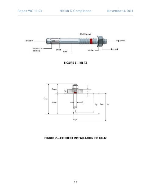
<str<strong>on</strong>g>Report</str<strong>on</strong>g> WC 11-03 <strong>Hilti</strong> <str<strong>on</strong>g>KB</str<strong>on</strong>g>-<str<strong>on</strong>g>TZ</str<strong>on</strong>g> Compliance November 4, 2011 FIGURE 1—<str<strong>on</strong>g>KB</str<strong>on</strong>g>-<str<strong>on</strong>g>TZ</str<strong>on</strong>g> FIGURE 2—CORRECT INSTALLATION OF <str<strong>on</strong>g>KB</str<strong>on</strong>g>-<str<strong>on</strong>g>TZ</str<strong>on</strong>g> 10
<str<strong>on</strong>g>Report</str<strong>on</strong>g> WC 11-03 <strong>Hilti</strong> <str<strong>on</strong>g>KB</str<strong>on</strong>g>-<str<strong>on</strong>g>TZ</str<strong>on</strong>g> Compliance November 4, 2011 DESIGN INFORMATION Symbol Units Anchor O.D. Effective min. embedment Min. member thickness Critical edge distance Min. edge distance Min. anchor spacing Min. hole depth in c<strong>on</strong>crete Min. specified yield strength Min. specified ult. strength Effective tensile stress area Steel strength in tensi<strong>on</strong> Steel strength in shear Steel strength in shear, seismic 5 Pullout strength uncracked c<strong>on</strong>crete 4 Pullout strength cracked c<strong>on</strong>crete 4 d o h ef h min c cr c min for s ≥ s min for c ≥ h o f y f u A se N s V s V seis N p,uncr N p,cr TABLE 1—<str<strong>on</strong>g>KB</str<strong>on</strong>g>-<str<strong>on</strong>g>TZ</str<strong>on</strong>g> DESIGN INFORMATION Nominal anchor diameter 3/8 1/2 5/8 3/4 in. 0.375 0.5 0.625 0.75 (mm) (9.5) (12.7) (15.9) (19.1) in. 2 2 3-1/4 3-1/8 4 3-3/4 4-3/4 (mm) (51) (51) (83) (79) (102) (95) (121) in. 4 5 4 6 6 8 5 6 8 6 8 8 (mm) (102) (127) (102) (152) (152) (203) (127) (152) (203) (152) (203) (203) in. 4-3/8 4 5-1/2 4-1/2 7-1/2 6 6-1/2 8-3/4 6-3/4 10 8 9 (mm) (111) (102) (140) (114) (191) (152) (165) (222) (171) (254) (203) (229) in. 2-1/2 2-3/4 2-3/8 3-5/8 3-1/4 4-3/4 4-1/8 (mm) (64) (70) (60) (92) (83) (121) (105) in. 5 5-3/4 5-3/4 6-1/8 5-7/8 10-1/2 8-7/8 (mm) (127) (146) (146) (156) (149) (267) (225) in. 2-1/2 2-3/4 2-3/8 3-1/2 3 5 4 (mm) (64) (70) (60) (89) (76) (127) (102) in. 3-5/8 4-1/8 3-1/2 4-3/4 4-1/4 9-1/2 7-3/4 (mm) (92) (105) (89) (121) (108) (241) (197) in. 2-5/8 2-5/8 4 3-7/8 4-3/4 4-1/2 5-3/4 (mm) (67) (67) (102) (98) (121) (117) (146) lb/in 2 100,000 84,800 84,800 84,800 (N/mm 2 ) (690) (585) (585) (585) lb/in 2 115,000 106,000 106,000 106,000 (N/mm 2 ) (862) (731) (731) (731) in 2 0.052 0.101 0.162 0.237 (mm 2 ) (33.6) (65.0) (104.6) (152.8) lb 6,500 10,705 17,170 25,120 (kN) (28.9) (47.6) (76.4) (111.8) lb 3,595 5,495 8,090 13,675 (kN) (16.0) (24.4) (36.0) (60.8) lb 2,255 5,495 7,600 11,745 (kN) (10.0) (24.4) (33.8) (52.2) lb 2,515 5,515 9,145 8,280 10,680 - - (kN) (11.2) (24.5) (40.7) (36.8) (47.5) lb 2,270 4,915 - (kN) (10.1) (21.9) - - - - Effectiveness factor k uncr uncracked c<strong>on</strong>crete 24 Effectiveness factor k cr cracked c<strong>on</strong>crete 2 17 3 = k uncr /k 3 cr 1.41 Strength reducti<strong>on</strong> factor for tensi<strong>on</strong>, steel failure modes 1 0.80 Strength reducti<strong>on</strong> factor for shear, steel failure modes 1 0.75 Strength reducti<strong>on</strong> factor for c<strong>on</strong>crete breakout, side-face blowout, pullout, or pryout failure 0.75 modes 1 For SI: 1 inch = 25.4 mm, 1 lbf = 4.45 N, 1 psi = 0.006895 MPa For pound-inch units: 1 mm = 0.03937 inches. 1 ACI 349-01, Appendix B, secti<strong>on</strong> B.4.4. For use with the load combinati<strong>on</strong>s of ACI 349-01, secti<strong>on</strong> 9.2. 2 ACI 349-01 Appendix B, secti<strong>on</strong> B.5.2.2 <strong>and</strong> B.5.2.8 3 ACI 349-01 Appendix B, secti<strong>on</strong> B.5.2.6 4 In lieu of ACI 349-01 Appendix B, secti<strong>on</strong> B.5.3.1 for pullout failure, N p,cr shall be used to calculate the pullout strength for cracked c<strong>on</strong>crete <strong>and</strong> N p,uncr shall be used to calculate the pullout strength for uncracked c<strong>on</strong>crete. The modificati<strong>on</strong> factor Ψ 4 shall then be taken as 1.0. 5 V seis shall be used in lieu of V s for load combinati<strong>on</strong>s that include earthquake loads. 11