Operating system verificationâAn overview
Operating system verificationâAn overview
Operating system verificationâAn overview

Create successful ePaper yourself
Turn your PDF publications into a flip-book with our unique Google optimized e-Paper software.
30 Gerwin Klein<br />
Design<br />
Requirements<br />
Ideas Intentions Expectations<br />
Specification<br />
Properties<br />
Theorem<br />
Prover<br />
Model<br />
Formal Logic Machine-Checkable Artefacts<br />
Implementation<br />
Physical Artefacts<br />
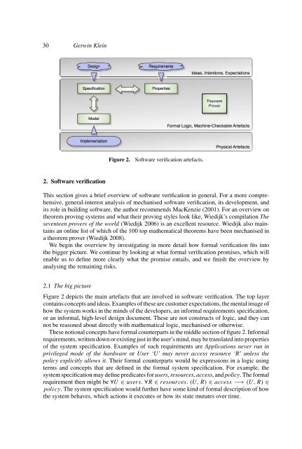
Figure 2.<br />
Software verification artefacts.<br />
2. Software verification<br />
This section gives a brief <strong>overview</strong> of software verification in general. For a more comprehensive,<br />
general-interest analysis of mechanised software verification, its development, and<br />
its role in building software, the author recommends MacKenzie (2001). For an <strong>overview</strong> on<br />
theorem proving <strong>system</strong>s and what their proving styles look like, Wiedijk’s compilation The<br />
seventeen provers of the world (Wiedijk 2006) is an excellent resource. Wiedijk also maintains<br />
an online list of which of the 100 top mathematical theorems have been mechanised in<br />
a theorem prover (Wiedijk 2008).<br />
We begin the <strong>overview</strong> by investigating in more detail how formal verification fits into<br />
the bigger picture. We continue by looking at what formal verification promises, which will<br />
enable us to define more clearly what the promise entails, and we finish the <strong>overview</strong> by<br />
analysing the remaining risks.<br />
2.1 The big picture<br />
Figure 2 depicts the main artefacts that are involved in software verification. The top layer<br />
contains concepts and ideas. Examples of these are customer expectations, the mental image of<br />
how the <strong>system</strong> works in the minds of the developers, an informal requirements specification,<br />
or an informal, high-level design document. These are not constructs of logic, and they can<br />
not be reasoned about directly with mathematical logic, mechanised or otherwise.<br />
These notional concepts have formal counterparts in the middle section of figure 2. Informal<br />
requirements, written down or existing just in the user’s mind, may be translated into properties<br />
of the <strong>system</strong> specification. Examples of such requirements are Applications never run in<br />
privileged mode of the hardware or User ‘U’ may never access resource ‘R’ unless the<br />
policy explicitly allows it. Their formal counterparts would be expressions in a logic using<br />
terms and concepts that are defined in the formal <strong>system</strong> specification. For example, the<br />
<strong>system</strong> specification may define predicates for users, resources, access, and policy. The formal<br />
requirement then might be ∀U ∈ users. ∀R ∈ resources. (U, R) ∈ access −→ (U, R) ∈<br />
policy. The <strong>system</strong> specification would further have some kind of formal description of how<br />
the <strong>system</strong> behaves, which actions it executes or how its state mutates over time.