Waveguides - ieeetsu
Waveguides - ieeetsu
Waveguides - ieeetsu

Create successful ePaper yourself
Turn your PDF publications into a flip-book with our unique Google optimized e-Paper software.
www.ece.rutgers.edu/∼orfanidi/ewa 273<br />
274 Electromagnetic Waves & Antennas – S. J. Orfanidis – June 21, 2004<br />
Although these expressions look different, they are actually equal, W e ′ = W m ′ . Indeed,<br />
using the property β 2 /k 2 c + 1 = (β2 + k 2 c )/k2 c = k2 /k 2 c = ω2 /ω 2 c and the relationships<br />
between the constants in (8.7.1), we find:<br />
µ ( |H 1 | 2 +|H 0 | 2) = µ ( |H 0 | 2 β2<br />
k 2 +|H 0 | 2) = µ|H 0 | 2 ω2<br />
c<br />
ωc<br />
2 = µ η |E 0| 2 = ɛ|E 2 0 | 2<br />
The equality of the electric and magnetic energies is a general property of waveguiding<br />
systems. We also encountered it in Sec. 2.3 for uniform plane waves. The total<br />
energy density per unit length will be:<br />
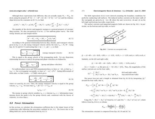
The field expressions (8.4.3) were derived assuming the boundary conditions for<br />
perfectly conducting wall surfaces. The induced surface currents on the inner walls of<br />
the waveguide are given by J s = ˆn × H, where the unit vector ˆn is ±ˆx and ±ŷ on the<br />
left/right and bottom/top walls, respectively.<br />
The surface currents and tangential magnetic fields are shown in Fig. 8.8.1. In particular,<br />
on the bottom and top walls, we have:<br />
W ′ = W ′ e + W′ m = 2W′ e = 1 4 ɛ|E 0| 2 ab (8.7.5)<br />
According to the general relationship between flux, density, and transport velocity<br />
given in Eq. (1.5.2), the energy transport velocity will be the ratio v en = P T /W ′ . Using<br />
Eqs. (8.7.4) and (8.7.5) and noting that 1/ηɛ = 1/ √ µɛ = c, we find:<br />
√<br />
v en = P T<br />
W ′ = c 1 − ω2 c<br />
(energy transport velocity) (8.7.6)<br />
ω 2<br />
This is equal to the group velocity of the propagating mode. For any dispersion<br />
relationship between ω and β, the group and phase velocities are defined by<br />
v gr = dω<br />
dβ ,<br />
v ph = ω β<br />
(group and phase velocities) (8.7.7)<br />
For uniform plane waves and TEM transmission lines, we have ω = βc, so that v gr =<br />
v ph = c. For a rectangular waveguide, we have ω 2 = ω 2 c + β2 c 2 . Taking differentials of<br />
both sides, we find 2ωdω = 2c 2 βdβ, which gives:<br />
√<br />
v gr = dω<br />
dβ = βc2<br />
ω<br />
= c 1 − ω2 c<br />
ω 2 (8.7.8)<br />
where we used Eq. (8.1.10). Thus, the energy transport velocity is equal to the group<br />
velocity, v en = v gr . We note that v gr = βc 2 /ω = c 2 /v ph ,or<br />
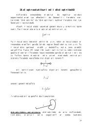
Fig. 8.8.1<br />
Currents on waveguide walls.<br />
J s =±ŷ × H =±ŷ × (ˆx H x + ẑH z )=±(−ẑ H x + ˆx H z )=±(−ẑ H 1 sin k c x + ˆx H 0 cos k c x)<br />
Similarly, on the left and right walls:<br />
J s =±ˆx × H =±ˆx × (ˆx H x + ẑH z )=∓ŷ H z =∓ŷ H 0 cos k c x<br />
At x = 0 and x = a, this gives J s =∓ŷ(±H 0 )= ŷ H 0 . Thus, the magnitudes of the<br />
surface currents are on the four walls:<br />
{<br />
|J s | 2 |H0 | 2 , (left and right walls)<br />
=<br />
|H 0 | 2 cos 2 k c x +|H 1 | 2 sin 2 k c x, (top and bottom walls)<br />
The power loss per unit z-length is obtained from Eq. (8.2.8) by integrating |J s | 2<br />
around the four walls, that is,<br />
P ′ loss = 2 1 2 R s<br />
∫ a<br />
0<br />
|J s | 2 dx + 2 1 2 R s<br />
∫ b<br />
0<br />
|J s | 2 dy<br />
v gr v ph = c 2 (8.7.9)<br />
The energy or group velocity satisfies v gr ≤ c, whereas v ph ≥ c. Information transmission<br />
down the guide is by the group velocity and, consistent with the theory of<br />
relativity, it is less than c.<br />
8.8 Power Attenuation<br />
In this section, we calculate the attenuation coefficient due to the ohmic losses of the<br />
conducting walls following the procedure outlined in Sec. 8.2. The losses due to the<br />
filling dielectric can be determined from Eq. (8.2.5).<br />
∫ a<br />
(<br />
= R s |H0 | 2 cos 2 k c x +|H 1 | 2 sin 2 k c x ) ∫ b<br />
dx + R s |H 0 | 2 dy<br />
0<br />
0<br />
a (<br />
= R s |H0 | 2 +|H 1 | 2) + R s b|H 0 | 2 = R sa (<br />
|H0 | 2 +|H 1 | 2 + 2b 2<br />
2<br />
a |H 0| 2)<br />
Using |H 0 | 2 +|H 1 | 2 =|E 0 | 2 /η 2 from Sec. 8.7, and |H 0 | 2 = (|E 0 | 2 /η 2 )ωc/ω 2 2 , which<br />
follows from Eq. (8.4.2), we obtain:<br />
P ′ loss = R sa|E 0 |<br />
(1 2<br />
+ 2b )<br />
ω 2 c<br />
2η 2 a ω 2<br />
The attenuation constant is computed from Eqs. (8.2.9) and (8.7.4):