Waveguides - ieeetsu
Waveguides - ieeetsu
Waveguides - ieeetsu

You also want an ePaper? Increase the reach of your titles
YUMPU automatically turns print PDFs into web optimized ePapers that Google loves.
www.ece.rutgers.edu/∼orfanidi/ewa 267<br />
268 Electromagnetic Waves & Antennas – S. J. Orfanidis – June 21, 2004<br />
Then, the corresponding electric field will be:<br />
where we defined the constants:<br />
E y (x)= −η TE H x (x)= −η TE<br />
jβ<br />
k c<br />
H 0 sin k c x ≡ E 0 sin k c x<br />
H 1 = jβ<br />
k c<br />
H 0<br />
E 0 =−η TE H 1 =−η TE<br />
jβ<br />
k c<br />
H 0 =−jη ω ω c<br />
H 0<br />
(8.4.2)<br />
where we used η TE = ηω/βc. In summary, the non-zero field components are:<br />
H z (x)= H 0 cos k c x<br />
H x (x)= H 1 sin k c x<br />
E y (x)= E 0 sin k c x<br />
⇒<br />
H z (x, y, z, t)= H 0 cos k c xe jωt−jβz<br />
H x (x, y, z, t)= H 1 sin k c xe jωt−jβz<br />
E y (x, y, z, t)= E 0 sin k c xe jωt−jβz (8.4.3)<br />
Assuming perfectly conducting walls, the boundary conditions require that there be<br />
no tangential electric field at any of the wall sides. Because the electric field is in the<br />
y-direction, it is normal to the top and bottom sides. But, it is parallel to the left and<br />
right sides. On the left side, x = 0, E y (x) vanishes because sin k c x does. On the right<br />
side, x = a, the boundary condition requires:<br />
E y (a)= E 0 sin k c a = 0 ⇒ sin k c a = 0<br />
This requires that k c a be an integral multiple of π:<br />
k c a = nπ ⇒ k c = nπ (8.4.4)<br />
a<br />
These are the so-called TE n0 modes. The corresponding cutoff frequency ω c = ck c ,<br />
f c = ω c /2π, and wavelength λ c = 2π/k c = c/f c are:<br />
ω c = cnπ<br />
a , f c = cn<br />
2a , λ c = 2a (TE n0 modes) (8.4.5)<br />
n<br />
The dominant mode is the one with the lowest cutoff frequency or the longest cutoff<br />
wavelength, that is, the mode TE 10 having n = 1. It has:<br />
k c = π a , ω c = cπ a , f c = c<br />
2a , λ c = 2a (TE 10 mode) (8.4.6)<br />
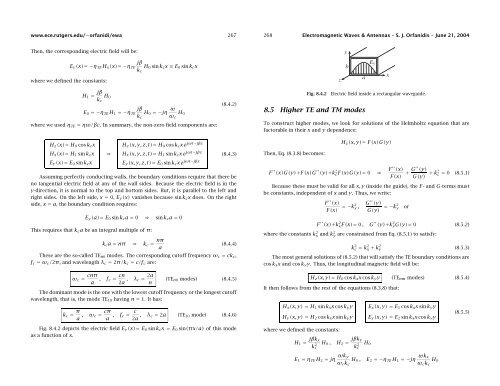
Fig. 8.4.2 depicts the electric field E y (x)= E 0 sin k c x = E 0 sin(πx/a) of this mode<br />
as a function of x.<br />
Fig. 8.4.2<br />
8.5 Higher TE and TM modes<br />
Electric field inside a rectangular waveguide.<br />
To construct higher modes, we look for solutions of the Helmholtz equation that are<br />
factorable in their x and y dependence:<br />
Then, Eq. (8.3.8) becomes:<br />
H z (x, y)= F(x)G(y)<br />
F ′′ (x)G(y)+F(x)G ′′ (y)+k 2 cF(x)G(y)= 0 ⇒ F′′ (x)<br />
F(x) + G′′ (y)<br />
G(y) + k2 c = 0 (8.5.1)<br />
Because these must be valid for all x, y (inside the guide), the F- and G-terms must<br />
be constants, independent of x and y. Thus, we write:<br />
F ′′ (x)<br />
F(x) =−k2 x ,<br />
G ′′ (y)<br />
G(y) =−k2 y<br />
F ′′ (x)+k 2 xF(x)= 0 , G ′′ (y)+k 2 yG(y)= 0 (8.5.2)<br />
where the constants k 2 x and k2 y are constrained from Eq. (8.5.1) to satisfy:<br />
k 2 c = k 2 x + k 2 y (8.5.3)<br />
The most general solutions of (8.5.2) that will satisfy the TE boundary conditions are<br />
cos k x x and cos k y y. Thus, the longitudinal magnetic field will be:<br />
H z (x, y)= H 0 cos k x x cos k y y (TE nm modes) (8.5.4)<br />
It then follows from the rest of the equations (8.3.8) that:<br />
H x (x, y) = H 1 sin k x x cos k y y<br />
H y (x, y) = H 2 cos k x x sin k y y<br />
where we defined the constants:<br />
H 1 = jβk x<br />
k 2 c<br />
H 0 ,<br />
H 2 = jβk y<br />
k 2 c<br />
H 0<br />
or<br />
E x (x, y) = E 1 cos k x x sin k y y<br />
E y (x, y) = E 2 sin k x x cos k y y<br />
(8.5.5)<br />
E 1 = η TE H 2 = jη ωk y<br />
ω c k c<br />
H 0 ,<br />
E 2 =−η TE H 1 =−jη ωk x<br />
ω c k c<br />
H 0