Waveguides - ieeetsu
Waveguides - ieeetsu
Waveguides - ieeetsu

You also want an ePaper? Increase the reach of your titles
YUMPU automatically turns print PDFs into web optimized ePapers that Google loves.
www.ece.rutgers.edu/∼orfanidi/ewa 277<br />
278 Electromagnetic Waves & Antennas – S. J. Orfanidis – June 21, 2004<br />
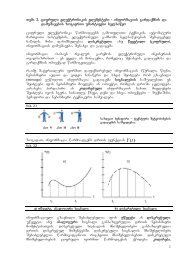
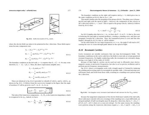
Fig. 8.9.1<br />
Reflection model of TE 10 mode.<br />
where the electric field was taken to be polarized in the y direction. These field expressions<br />
become component-wise:<br />
E y = ( E 1 e −jkxx + E ′ 1e jkxx) e −jkzz<br />
H x =− 1 η sin θ( E 1 e −jkxx + E ′ 1e jkxx) e −jkzz<br />
H z = 1 η cos θ( E 1 e −jkxx − E ′ 1e jkxx) e −jkzz (8.9.1)<br />
The boundary condition on the left wall, x = 0, requires that E 1 + E ′ 1 = 0. We may write<br />
therefore, E 1 =−E ′ 1 = jE 0 /2. Then, the above expressions simplify into:<br />
E y = E 0 sin k x xe −jkzz<br />
H x =− 1 η sin θE 0 sin k x xe −jkzz<br />
H z = j η cos θE 0 cos k x xe −jkzz (8.9.2)<br />
The boundary condition on the right wall requires sin k x a = 0, which gives rise to<br />
the same condition as (8.4.4), that is, k c a = nπ.<br />
This model clarifies also the meaning of the group velocity. The plane wave is bouncing<br />
left and right with the speed of light c. However, the component of this velocity in<br />
the z-direction will be v z = c sin θ. This is equal to the group velocity. Indeed, it follows<br />
from Eq. (8.9.3) that:<br />
v z = c sin θ = c 1 − ω2 c<br />
ω = v 2 gr (8.9.5)<br />
Eq. (8.9.3) implies also that at ω = ω c , we have sin θ = 0, or θ = 0, that is, the wave<br />
is bouncing left and right at normal incidence, creating a standing wave, and does not<br />
propagate towards the z-direction. Thus, the transmitted power is zero and this also<br />
implies, through Eq. (8.2.9), that α c will be infinite.<br />
On the other hand, for very large frequencies, ω ≫ ω c , the angle θ will tend to 90 o ,<br />
causing the wave to zoom through guide almost at the speed of light.<br />
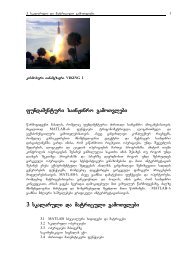
8.10 Resonant Cavities<br />
Cavity resonators are metallic enclosures that can trap electromagnetic fields. The<br />
boundary conditions on the cavity walls force the fields to exist only at certain quantized<br />
resonant frequencies. For highly conducting walls, the resonances are extremely sharp,<br />
having a very high Q of the order of 10,000.<br />
Because of their high Q, cavities can be used not only to efficiently store electromagnetic<br />
energy at microwave frequencies, but also to act as precise oscillators and to<br />
perform precise frequency measurements.<br />
Fig. 8.10.1 shows a rectangular cavity with z-length equal to l formed by replacing<br />
the sending and receiving ends of a waveguide by metallic walls. A forward-moving wave<br />
will bounce back and forth from these walls, resulting in a standing-wave pattern along<br />
the z-direction.<br />
√<br />
These are identical to Eq. (8.4.3) provided we identify β with k z and k c with k x ,as<br />
shown in Fig. 8.9.1. It follows from the wavevector triangle in the figure that the angle<br />
of incidence θ will be given by cos θ = k x /k = k c /k, or,<br />
cos θ = ω c<br />
ω ,<br />
sin θ = √<br />
1 − ω2 c<br />
ω 2 (8.9.3)<br />
The ratio of the transverse components, −E y /H x , is the transverse impedance, which<br />
is recognized to be η TE . Indeed, we have:<br />
η TE =− E y<br />
=<br />
η<br />
H x sin θ = √<br />
η<br />
1 − ω2 c<br />
ω 2 (8.9.4)<br />
Fig. 8.10.1<br />
Rectangular cavity resonator (and induced wall currents for the TE n0p mode.)<br />
Because the tangential components of the electric field must vanish at the end-walls,<br />
these walls must coincide with zero crossings of the standing wave, or put differently, an<br />
integral multiple of half-wavelengths must fit along the z-direction, that is, l = pλ g /2 =<br />
pπ/β, orβ = pπ/l, where p is a non-zero integer. For the same reason, the standingwave<br />
patterns along the transverse directions require a = nλ x /2 and b = mλ y /2, or