Waveguides - ieeetsu
Waveguides - ieeetsu
Waveguides - ieeetsu

Create successful ePaper yourself
Turn your PDF publications into a flip-book with our unique Google optimized e-Paper software.
www.ece.rutgers.edu/∼orfanidi/ewa 265<br />
266 Electromagnetic Waves & Antennas – S. J. Orfanidis – June 21, 2004<br />
TE modes<br />
TE modes are characterized by the conditions E z = 0 and H z ≠ 0. It follows from the<br />
second of Eqs. (8.1.17) that E T is completely determined from H T , that is, E T = η TE H T ×ẑ.<br />
The field H T is determined from the second of (8.1.16). Thus, all field components<br />
for TE modes are obtained from the equations:<br />
∇T 2 H z + k 2 cH z = 0<br />
H T =− jβ<br />
k 2 ∇ T H z<br />
c<br />
E T = η TE H T × ẑ<br />
(TE modes) (8.3.6)<br />
The relationship of E T and H T is identical to that of uniform plane waves propagating<br />
in the z-direction, except the wave impedance is replaced by η TE . The Poynting vector<br />
of Eq. (8.2.2) then takes the form:<br />
P z = 1 2 Re(E T × H ∗ T )·ẑ = 1 |E T | 2 = 1 2η TE 2 η TE|H T | 2 = 1 2 η β 2<br />
TE<br />
k 4 |∇ T H z | 2 (8.3.7)<br />
c<br />
The cartesian coordinate version of Eq. (8.3.6) is:<br />
∇ 2 T E z + k 2 c E z = 0<br />
E T =− jβ<br />
k 2 ∇ T E z<br />
c<br />
H T = 1 ẑ × E T<br />
η TM<br />
(TM modes) (8.3.10)<br />
Again, the relationship of E T and H T is identical to that of uniform plane waves<br />
propagating in the z-direction, but the wave impedance is now η TM . The Poynting vector<br />
takes the form:<br />
P z = 1 2 Re(E T × H ∗ T )·ẑ = 1 |E T | 2 = 1 β 2<br />
2η TM 2η TM k 4 |∇ T E z | 2 (8.3.11)<br />
c<br />
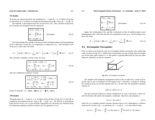
8.4 Rectangular <strong>Waveguides</strong><br />
Next, we discuss in detail the case of a rectangular hollow waveguide with conducting<br />
walls, as shown in Fig. 8.4.1. Without loss of generality, we may assume that the lengths<br />
a, b of the inner sides satisfy b ≤ a. The guide is typically filled with air, but any other<br />
dielectric material ɛ, µ may be assumed.<br />
(∂ 2 x + ∂ 2 y)H z + k 2 cH z = 0<br />
H x =− jβ ∂ x H z ,<br />
H y =− jβ ∂ y H z<br />
(8.3.8)<br />
k 2 c<br />
k 2 c<br />
And, the cylindrical coordinate version:<br />
(<br />
1 ∂<br />
ρ ∂H )<br />
z<br />
+ 1 ∂ 2 H z<br />
ρ ∂ρ ∂ρ ρ 2 ∂φ + 2 k2 c H z = 0<br />
H ρ =− jβ ∂H z<br />
k 2 , H φ =− jβ 1 ∂H z<br />
(8.3.9)<br />
c ∂ ρ k 2 c ρ ∂ φ<br />
E ρ = η TE H φ , E φ =−η TE H ρ<br />
where we used H T × ẑ = (ˆρH ρ + ˆφH φ )×ẑ =−ˆφH ρ + ˆρH φ .<br />
TM modes<br />
TM modes have H z = 0 and E z ≠ 0. It follows from the first of Eqs. (8.1.17) that H T is<br />
completely determined from E T , that is, H T = η −1<br />
TMẑ × E T. The field E T is determined<br />
from the first of (8.1.16), so that all field components for TM modes are obtained from<br />
the following equations, which are dual to the TE equations (8.3.6):<br />
Fig. 8.4.1<br />
Rectangular waveguide.<br />
The simplest and dominant propagation mode is the so-called TE 10 mode and depends<br />
only on the x-coordinate (of the longest side.) Therefore, we begin by looking<br />
for solutions of Eq. (8.3.8) that depend only on x. In this case, the Helmholtz equation<br />
reduces to:<br />
∂ 2 xH z (x)+k 2 cH z (x)= 0<br />
The most general solution is a linear combination of cos k c x and sin k c x. However,<br />
only the former will satisfy the boundary conditions. Therefore, the solution is:<br />
H z (x)= H 0 cos k c x (8.4.1)<br />
where H 0 is a (complex-valued) constant. Because there is no y-dependence, it follows<br />
from Eq. (8.3.8) that ∂ y H z = 0, and hence H y = 0 and E x = 0. It also follows that:<br />
H x (x)= − jβ<br />
k 2 c<br />
∂ x H z =− jβ<br />
k 2 (−k c )H 0 sin k c x = jβ H 0 sin k c x ≡ H 1 sin k c x<br />
c<br />
k c