Waveguides - ieeetsu
Waveguides - ieeetsu
Waveguides - ieeetsu

You also want an ePaper? Increase the reach of your titles
YUMPU automatically turns print PDFs into web optimized ePapers that Google loves.
www.ece.rutgers.edu/∼orfanidi/ewa 279<br />
280 Electromagnetic Waves & Antennas – S. J. Orfanidis – June 21, 2004<br />
k x = nπ/a and k y = mπ/b. Thus, all three cartesian components of the wave vector<br />
√<br />
are quantized, and therefore, so is the frequency of the wave ω = c kx 2 + k 2 y + β 2 :<br />
√ ( ) nπ 2 ( ) mπ 2 ( ) pπ 2<br />
ω nmp = c + +<br />
(resonant frequencies) (8.10.1)<br />
a b l<br />
Such modes are designated as TE nmp or TM nmp . For simplicity, we consider the case<br />
TE n0p . Eqs. (8.3.6) also describe backward-moving waves if one replaces β by −β, which<br />
also changes the sign of η TE = ηω/βc. Starting with a linear combination of forward<br />
and backward waves in the TE n0 mode, we obtain the field components:<br />
H z (x, z) = H 0 cos k c x ( Ae −jβz + Be jβz) ,<br />
H x (x, z) = jH 1 sin k c x ( Ae −jβz − Be jβz) , H 1 = β k c<br />
H 0<br />
E y (x, z) =−jE 0 sin k c x ( Ae −jβz + Be jβz) , E 0 = ω ω c<br />
ηH 0<br />
(8.10.2)<br />
where ω c = ck c . By requiring that E y (x, z) have z-dependence of the form sin βz, the<br />
coefficients A, B must be chosen as A =−B = j/2. Then, Eq. (8.10.2) specializes into:<br />
H z (x, z) = H 0 cos k c x sin βz ,<br />
H x (x, z) =−H 1 sin k c x cos βz , H 1 = β k c<br />
H 0<br />
E y (x, z) =−jE 0 sin k c x sin βz , E 0 = ω ω c<br />
ηH 0<br />
(8.10.3)<br />
As expected, the vanishing of E y (x, z) on the front/back walls, z = 0 and z = l, and<br />
on the left/right walls, x = 0 and x = a, requires the quantization conditions: β = pπ/l<br />
and k c = nπ/a. The Q of the resonator can be calculated from its definition:<br />
Q = ω<br />
W<br />
(8.10.4)<br />
P loss<br />
where W is the total time-averaged energy stored within the cavity volume and P loss is<br />
the total power loss due to the wall ohmic losses (plus other losses, such as dielectric<br />
losses, if present.) The ratio ∆ω = P loss /W is usually identified as the 3-dB width of the<br />
resonance centered at frequency ω. Therefore, we may write Q = ω/∆ω.<br />
It is easily verified that the electric and magnetic energies are equal, therefore, W<br />
may be calculated by integrating the electric energy density over the cavity volume:<br />
W = 2W e = 2 1 ∫<br />
ɛ|E y (x, z)| 2 dx dy dz = 1 ∫ a<br />
∫ b<br />
∫ l<br />
4 vol 2 ɛ|E 0| 2 sin 2 k c x cos 2 βz dx dy dz<br />
0 0 0<br />
[ ]<br />
= 1 8 ɛ|E 0| 2 (abl)= 1 8 µ|H 0| 2 ω2<br />
ω 2 (abl)= 1 k<br />
c 8 µ |H 0| 2 2<br />
c + β 2<br />
k 2 (abl)<br />
c<br />
where we used the following definite integrals (valid because k c = nπ/a, β = pπ/l):<br />
∫ a<br />
∫ a<br />
sin 2 k c xdx= cos 2 k c xdx= a ∫ l<br />
∫ l<br />
0<br />
0<br />
2 , sin 2 βz dz = cos 2 βz dz = l (8.10.5)<br />
0<br />
0<br />
2<br />
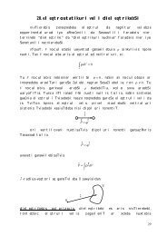
The ohmic losses are calculated from Eq. (8.2.6), integrated over all six cavity sides.<br />
The surface currents induced on the walls are related to the tangential magnetic fields<br />
by J s = ˆn × H tan . The directions of these currents are shown in Fig. 8.10.1. Specifically,<br />
we find for the currents on the six sides:<br />
⎧<br />
⎪⎨<br />
H0 2 sin2 βz<br />
(left & right)<br />
|J s | 2 = H0 2 ⎪⎩<br />
cos2 k c x sin 2 βz + H1 2 sin2 k c x cos 2 βz (top & bottom)<br />
H1 2 sin2 k c x<br />
(front & back)<br />
The power loss can be computed by integrating the loss per unit conductor area,<br />
Eq. (8.2.6), over the six wall sides, or doubling the answer for the left, top, and front<br />
sides. Using the integrals (8.10.5), we find:<br />
P loss = 1 ∫<br />
2 R s |J s | 2 dA = R s<br />
[H 2 bl<br />
0<br />
walls<br />
2 + (H2 0 + H1) 2 al ]<br />
4 + ab<br />
H2 1<br />
2<br />
[<br />
]<br />
= 1 (8.10.6)<br />
4 R sH0<br />
2 l(2b + a)+ β2<br />
k 2 a(2b + l)<br />
c<br />
where we substituted H1 2 = H0β 2 2 /kc 2 . It follows that the Q-factor will be:<br />
Q = ω<br />
W = ωµ (k 2 c + β2 )(abl)<br />
P loss 2R s k 2 cl(2b + a)+β 2 a(2b + l)<br />
For the TE n0p mode we have β = pπ/l and k c = nπ/a. Using Eq. (8.2.7) to replace<br />
R s in terms of the skin depth δ, we find:<br />
n 2<br />
Q = 1 a + p2<br />
2 l 2<br />
δ n 2 ( 2<br />
a 2 a + 1 ) (<br />
+ p2 2<br />
b l 2 l + 1 ) (8.10.7)<br />
b<br />
The lowest resonant frequency corresponds to n = p = 1. For a cubic cavity, a =<br />
b = l, the Q and the lowest resonant frequency are:<br />
Q = a<br />
3δ , ω 101 = cπ√ 2<br />
a<br />
, f 101 = ω 2π = c<br />
a √ 2<br />
(8.10.8)<br />
For an air-filled cubic cavity with a = 3 cm, we find f 101 = 7.07 GHz, δ = 7.86×10 −5<br />
cm, and Q = 12724. As in waveguides, cavities can be excited by inserting small probes<br />
that generate fields resembling a particular mode.<br />
8.11 Dielectric Slab <strong>Waveguides</strong><br />
A dielectric slab waveguide is a planar dielectric sheet or thin film of some thickness,<br />
say 2a, as shown in Fig. 8.11.1. Wave propagation in the z-direction is by total internal<br />
reflection from the left and right walls of the slab. Such waveguides provide simple<br />
models for the confining mechanism of waves propagating in optical fibers.