Waveguides - ieeetsu
Waveguides - ieeetsu
Waveguides - ieeetsu

Create successful ePaper yourself
Turn your PDF publications into a flip-book with our unique Google optimized e-Paper software.
www.ece.rutgers.edu/∼orfanidi/ewa 271<br />
272 Electromagnetic Waves & Antennas – S. J. Orfanidis – June 21, 2004<br />
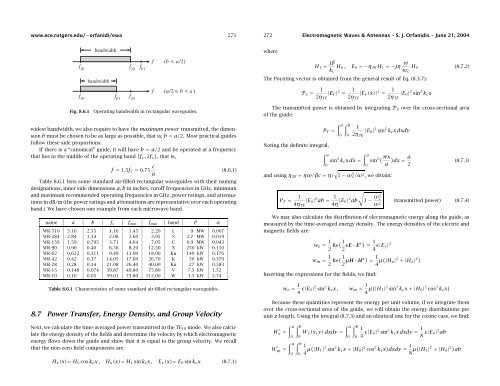
Fig. 8.6.1<br />
Operating bandwidth in rectangular waveguides.<br />
where<br />
H 1 = jβ H 0 , E 0 =−η TE H 1 =−jη ω H 0 (8.7.2)<br />
k c ω c<br />
The Poynting vector is obtained from the general result of Eq. (8.3.7):<br />
P z = 1<br />
2η TE<br />
|E T | 2 = 1<br />
2η TE<br />
|E y (x)| 2 = 1<br />
2η TE<br />
|E 0 | 2 sin 2 k c x<br />
The transmitted power is obtained by integrating P z over the cross-sectional area<br />
of the guide:<br />
widest bandwidth, we also require to have the maximum power transmitted, the dimension<br />
b must be chosen to be as large as possible, that is, b = a/2. Most practical guides<br />
follow these side proportions.<br />
If there is a “canonical” guide, it will have b = a/2 and be operated at a frequency<br />
that lies in the middle of the operating band [f c , 2f c ], that is,<br />
f = 1.5f c = 0.75 c (8.6.1)<br />
a<br />
Table 8.6.1 lists some standard air-filled rectangular waveguides with their naming<br />
designations, inner side dimensions a, b in inches, cutoff frequencies in GHz, minimum<br />
and maximum recommended operating frequencies in GHz, power ratings, and attenuations<br />
in dB/m (the power ratings and attenuations are representative over each operating<br />
band.) We have chosen one example from each microwave band.<br />
name a b f c f min f max band P α<br />
WR-510 5.10 2.55 1.16 1.45 2.20 L 9 MW 0.007<br />
WR-284 2.84 1.34 2.08 2.60 3.95 S 2.7 MW 0.019<br />
WR-159 1.59 0.795 3.71 4.64 7.05 C 0.9 MW 0.043<br />
WR-90 0.90 0.40 6.56 8.20 12.50 X 250 kW 0.110<br />
WR-62 0.622 0.311 9.49 11.90 18.00 Ku 140 kW 0.176<br />
WR-42 0.42 0.17 14.05 17.60 26.70 K 50 kW 0.370<br />
WR-28 0.28 0.14 21.08 26.40 40.00 Ka 27 kW 0.583<br />
WR-15 0.148 0.074 39.87 49.80 75.80 V 7.5 kW 1.52<br />
WR-10 0.10 0.05 59.01 73.80 112.00 W 3.5 kW 2.74<br />
Table 8.6.1 Characteristics of some standard air-filled rectangular waveguides.<br />
8.7 Power Transfer, Energy Density, and Group Velocity<br />
Next, we calculate the time-averaged power transmitted in the TE 10 mode. We also calculate<br />
the energy density of the fields and determine the velocity by which electromagnetic<br />
energy flows down the guide and show that it is equal to the group velocity. We recall<br />
that the non-zero field components are:<br />
H z (x)= H 0 cos k c x, H x (x)= H 1 sin k c x, E y (x)= E 0 sin k c x (8.7.1)<br />
Noting the definite integral,<br />
∫ a<br />
∫ b<br />
P T =<br />
0 0<br />
1<br />
2η TE<br />
|E 0 | 2 sin 2 k c x dxdy<br />
∫ a<br />
∫ a<br />
sin 2 k c xdx= sin<br />
2( πx ) a dx =<br />
0<br />
0 a 2<br />
√<br />
and using η TE = ηω/βc = η/ 1 − ω 2 c/ω 2 , we obtain:<br />
(8.7.3)<br />
√<br />
P T = 1 |E 0 | 2 ab = 1<br />
4η TE 4η |E 0| 2 ab 1 − ω2 c<br />
ω 2 (transmitted power) (8.7.4)<br />
We may also calculate the distribution of electromagnetic energy along the guide, as<br />
measured by the time-averaged energy density. The energy densities of the electric and<br />
magnetic fields are:<br />
w e = 1 2 Re( 1 2 ɛE · E∗) = 1 4 ɛ|E y| 2<br />
w m = 1 2 Re( 1 2 µH · H∗) = 1 4 µ( |H x | 2 +|H z | 2)<br />
Inserting the expressions for the fields, we find:<br />
w e = 1 4 ɛ|E 0| 2 sin 2 k c x, w m = 1 4 µ( |H 1 | 2 sin 2 k c x +|H 0 | 2 cos 2 k c x )<br />
Because these quantities represent the energy per unit volume, if we integrate them<br />
over the cross-sectional area of the guide, we will obtain the energy distributions per<br />
unit z-length. Using the integral (8.7.3) and an identical one for the cosine case, we find:<br />
W ′ e = ∫ a<br />
0<br />
W ′ m = ∫ a<br />
0<br />
∫ b<br />
0<br />
∫ b<br />
0<br />
∫ a<br />
∫ b<br />
W e (x, y) dxdy =<br />
0 0<br />
1<br />
4 ɛ|E 0| 2 sin 2 k c x dxdy = 1 8 ɛ|E 0| 2 ab<br />
1<br />
4 µ( |H 1 | 2 sin 2 k c x +|H 0 | 2 cos 2 k c x ) dxdy = 1 8 µ( |H 1 | 2 +|H 0 | 2) ab