News & Events - Institution of Engineers Singapore
News & Events - Institution of Engineers Singapore
News & Events - Institution of Engineers Singapore

You also want an ePaper? Increase the reach of your titles
YUMPU automatically turns print PDFs into web optimized ePapers that Google loves.
Lutron® | NEW Radio Powr SavrTM<br />
wireless occupancy and vacancy sensor<br />
A simple way to go green<br />
©2010 Lutron Electronics Co., Inc.
Contents<br />
Section 1: Engineering (General)<br />
2 IES Update<br />
Section 2: Engineering (Civil & Structural • Infrastructural<br />
• Environmental Focus)<br />
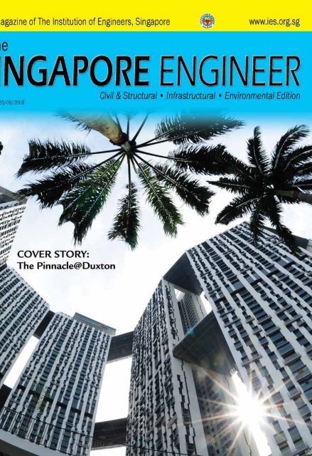
10 Cover Story: The Pinnacle@Duxton<br />
Published By<br />
The <strong>Institution</strong> <strong>of</strong> <strong>Engineers</strong>, <strong>Singapore</strong><br />
Director, Marketing<br />
Roland Ang<br />
Marketing & Publications Executive<br />
Jeremy Chia<br />
22 Structural Engineering: Burj Khalifa Tower<br />
30 Interview: Engineering urban transformation<br />
32 Products & Services<br />
38 Section 3: <strong>News</strong> & <strong>Events</strong><br />
Chief Editor<br />
T Bhaskaran<br />
Editorial Board<br />
Er. Dr Adhityan Appan<br />
Mr Lee Siew Wei<br />
Er. Siow Keng Cheng<br />
Mr Wong Chung Wan<br />
Manager, External Relations<br />
Valerie Neo<br />
Cover designed by Jeremy Chia<br />
Cover image by HDB<br />
The <strong>Singapore</strong> Engineer, The Magazine <strong>of</strong> the <strong>Institution</strong> <strong>of</strong><br />
<strong>Engineers</strong>, <strong>Singapore</strong> (IES) is published on a monthly basis,<br />
by the <strong>Institution</strong> <strong>of</strong> <strong>Engineers</strong>, <strong>Singapore</strong>.<br />
The contents within the magazine, unless explicitly stated otherwise, do not reflect the opinions <strong>of</strong> the <strong>Institution</strong> <strong>of</strong> <strong>Engineers</strong>,<br />
<strong>Singapore</strong> (IES), and therefore have not received any endorsement from IES. The Editor reserves the right to amend, add to,<br />
condense, or rewrite, any editorial release or submission.<br />
The title The <strong>Singapore</strong> Engineer is the property <strong>of</strong> the<br />
<strong>Institution</strong> <strong>of</strong> <strong>Engineers</strong>, <strong>Singapore</strong> (IES).<br />
Although all efforts will be made to ensure that information is accurate at the time <strong>of</strong> going to print, the Publisher and Editor,<br />
as well as the <strong>Institution</strong> <strong>of</strong> <strong>Engineers</strong>, <strong>Singapore</strong> (IES), will not accept any liability for errors within the magazine.<br />
© The <strong>Institution</strong> <strong>of</strong> <strong>Engineers</strong>, <strong>Singapore</strong>. The copyright<br />
<strong>of</strong> the contents <strong>of</strong> The <strong>Singapore</strong> Engineer is held by the<br />
Publisher. All rights reserved. Reproduction <strong>of</strong> information<br />
contained within the magazine, in its entirety, or in part, in<br />
any format, requires written permission from the Publisher.<br />
The publication is distributed free-<strong>of</strong>-charge. For enquiries on Editorial and Advertising, please contact the <strong>Institution</strong> <strong>of</strong><br />
<strong>Engineers</strong>, <strong>Singapore</strong>, 70 Bukit Tinggi Road, <strong>Singapore</strong> 289758. Tel: (65) 6469 5000 Fax: (65) 64671108.<br />
Printed in <strong>Singapore</strong> by SUN RISE Printing & Supplies Pte Ltd.<br />
THE SINGAPORE ENGINEER Jun 2010 · 1
IES Update<br />
Message from the President<br />
IES COUNCIL MEMBERS<br />
2010/2011<br />
President<br />
Er. Ho Siong Hin<br />
Vice Presidents<br />
Er. Chong Kee Sen<br />
Er. Pr<strong>of</strong> Chou Siaw Kiang<br />
Er. Edwin Khew<br />
Er. Lum Chong Chuen<br />
Er. Ong See Ho<br />
Pr<strong>of</strong> Yeoh Lean Weng<br />
Honorary Secretary<br />
Er. Ng Say Cheong<br />
Honorary Treasurer<br />
Assoc Pr<strong>of</strong> Daniel Lim<br />
Assistant Honorary Secretary<br />
Er. Jee Yi Yng<br />
Assistant Honorary Treasurer<br />
Mr Jeffrey Chua<br />
Immediate Past President<br />
Er. Lee Bee Wah<br />
Past Presidents<br />
Er. Tan Seng Chuan<br />
Er. A/Pr<strong>of</strong> Foo Say Wei<br />
Er. Ong Ser Huan<br />
Council Members<br />
Dr Boh Jaw Woei<br />
Pr<strong>of</strong> Er Meng Joo<br />
Er. Koh Beng Thong<br />
Mr Lim Shiyi<br />
Er. Low Wong Fook<br />
Mr Neo Kok Beng<br />
Er. Ong Geok Soo<br />
Er. Pr<strong>of</strong> Ong Say Leong<br />
Er. Pak Yew Hock, Lawrence<br />
Pr<strong>of</strong> Seeram Ramakrishna<br />
Mr Tan Kai Hong<br />
Er. Toh Siaw Hui, Joseph<br />
Mr Alfred Wong<br />
Dear Friends<br />
As the new President <strong>of</strong> IES, I welcome the opportunity to communicate with the<br />
readers <strong>of</strong> ‘The <strong>Singapore</strong> Engineer’ on a regular basis.<br />
In the last few weeks, we have seen how the blow-out <strong>of</strong> the oil well on the seabed<br />
in the Gulf <strong>of</strong> Mexico has played out for BP. The incident caused an explosion on<br />
the <strong>of</strong>fshore oil drilling platform, killing 11 workers and injuring 17 others. It also<br />
resulted in a massive oil spill that continues to threaten the east coast <strong>of</strong> the US, on an<br />
unprecedented scale. Efforts to cap the oil are ongoing but a lot <strong>of</strong> damage has already<br />
been done.<br />
This man-made disaster is an example <strong>of</strong> the consequences to human life, assets, and<br />
the environment (in this instance directly affecting the livelihoods <strong>of</strong> people), when<br />
production operations go wrong. A myriad <strong>of</strong> questions strike our minds: Why did the<br />
explosion happen? Were all the safety measures including those relating to materials,<br />
equipment, instrumentation, personnel and procedures etc, in place, that could have<br />
prevented it? Were scenarios for different kinds <strong>of</strong> abnormal situations visualised, and<br />
response measures developed, prioritised, and simulated?<br />
What we can say is that, as far as possible, such a situation should never be allowed<br />
to happen. The subject <strong>of</strong> safety should be given top priority, so that human beings,<br />
property, and the environment, are protected at all times.<br />
<strong>Engineers</strong> have a major role to play in the achievement <strong>of</strong> this objective. Backed by<br />
their technical knowledge and experience, they can take the lead in the development<br />
and implementation <strong>of</strong> safety measures and post-accident response programmes.<br />
This is why we place paramount importance on workplace safety in IES. The IES<br />
Academy has been organising training courses with an emphasis on safety to inculcate<br />
the ‘safety first’ mindset in our engineers. Lessons to be learnt from accidents in<br />
our recent memory, such as the Nicoll Highway collapse and the Marina Bay Sands<br />
fatality, are imparted to our engineers through relevant seminars and courses. Through<br />
education we hope that the safety mindset will be prevalent among our engineers.<br />
Er. Ho Siong Hin<br />
President<br />
The <strong>Institution</strong> <strong>of</strong> <strong>Engineers</strong>, <strong>Singapore</strong> (IES)<br />
2 · THE SINGAPORE ENGINEER Jun 2010
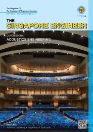
IES Update<br />
EAB workshop on ‘Developing Sustainable<br />
Program Assessment Processes’<br />
The workshop on ‘Developing<br />
Sustainable Program Assessment<br />
Processes’ by Dr Gloria Rogers, Managing<br />
Director, Pr<strong>of</strong>essional Services, ABET<br />
Inc, was organised by the Engineering<br />
Accreditation Board (EAB) <strong>of</strong> IES from<br />
10 May to 12 May 2010 at Furama<br />
Riverfront Hotel.<br />
The intention <strong>of</strong> the workshop was<br />
to prepare all local universities for the<br />
outcome-based accreditation which will<br />
be in place in Year 2012.<br />
The three-day workshop saw a total<br />
<strong>of</strong> 60 participants hailing from Nanyang<br />
Technological University (NTU),<br />
National University <strong>of</strong> <strong>Singapore</strong><br />
(NUS), and SIM University (UniSIM).<br />
All participants were actively involved in<br />
the programme lined up by Dr Rogers.<br />
At the end <strong>of</strong> the workshop, a<br />
majority <strong>of</strong> the participants (85%) gave<br />
the feedback that rubrics writing and<br />
designing good surveys are the most<br />
useful and meaningful lessons they have<br />
learnt.<br />
Many also commented that they<br />
enjoyed the activities i.e the table<br />
discussion and silent brainstorming, and<br />
the ‘toys’ provided by Dr Rogers.<br />
EAB workshop participants.<br />
Pr<strong>of</strong> Fung Tat Ching (NTU) explaining the<br />
written performance indicators to fellow group<br />
members.<br />
Dr Rogers examines the performance indicators<br />
written by A/Pr<strong>of</strong> Chen Zhong’s (NTU) group.<br />
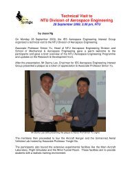
Courtesy visit by IFEES<br />
On 17 May 2010, Dr Lueny Morell,<br />
President, International Federation<br />
<strong>of</strong> Engineering Education Societies<br />
(IFEES), paid a courtesy visit to IES.<br />
Accompanying her was Dr John<br />
Lamancusa, Pr<strong>of</strong>essor, Department <strong>of</strong><br />
Mechanical and Nuclear Engineering,<br />
The Pennsylvania State University, USA.<br />
The IFEES representatives were<br />
received by Er. Ng Say Cheong, IES<br />
Honorary Secretary; Er. Ong Ser Huan,<br />
IES Past President; A/Pr<strong>of</strong> Daniel Lim,<br />
IES Honorary Treasurer; and Er. Dr<br />
Chew Soon Hoe, Past Chairman <strong>of</strong> the<br />
National Committee <strong>of</strong> Engineering<br />
Organisations (NCEO).<br />
The parties exchanged updates on<br />
their respective institutions and how IES<br />
can play a role in the upcoming World<br />
Engineering Education Forum (WEEF)<br />
in October 2010. The meeting ended with<br />
a presentation <strong>of</strong> tokens and a dinner<br />
hosted by IES.<br />
From left to right: Dr Low Eicher, Acting Executive Director, IES; Er. Dr Chew Soon Hoe; Er. Ong<br />
Ser Huan; Dr Lueny Morell; Dr John Lamancusa; Er. Ng Say Cheong; and A/Pr<strong>of</strong> Daniel Lim.<br />
4 · THE SINGAPORE ENGINEER Jun 2010
IES Update<br />
H.K.U. Engineering Alumni Association’s<br />
(HKUEAA) Sustainable Development Study<br />
Tour to <strong>Singapore</strong><br />
On 2 June 2010, 17 delegates from the<br />
H.K.U. Engineering Alumni Association<br />
(HKUEAA) paid a courtesy visit to<br />
IES. The HKUEAA delegates were in<br />
<strong>Singapore</strong> for a three-day study tour with<br />
the theme ‘Sustainable City’. HKUEAA,<br />
founded to promote friendship amongst<br />
Engineering graduates from the University<br />
<strong>of</strong> Hong Kong (HKU) and to initiate<br />
and assist the pr<strong>of</strong>essional furtherance<br />
within and outside the campus, has<br />
been aggressively promoting sustainable<br />
development (SD) by having experiential<br />
projects for HKU engineering alumni and<br />
students to appreciate the examples <strong>of</strong> SD<br />
outside Hong Kong. The delegation has<br />
identified <strong>Singapore</strong> as a good example<br />
demonstrating the sustainable city<br />
development concepts.<br />
The HKUEAA delegation was received<br />
by Er. Ho Siong Hin, IES President;<br />
Er. Lawrence Pak, Chairman, Civil and<br />
Structural Technical Committee; Ms Titis<br />
Primita, Vice Chairman, Young Members<br />
Committee; Er. Dr Lim Ewe Chye,<br />
Chairman, IES Clean Energy Interest<br />
Group; and Dr Low Eicher, Acting<br />
Executive Director.<br />
Besides visiting IES, the delegation<br />
also visited the Urban Redevelopment<br />
Authority (URA) Gallery; ARUP<br />
<strong>Singapore</strong>’s <strong>of</strong>fice; Building and<br />
Construction Authority’s (BCA) Zero<br />
Energy Building; Solar Technology Centre<br />
at Ngee Ann Polytechnic; Gardens by the<br />
Bay Visitor Centre; NEWater Visitor<br />
Centre; Changi Water Reclamation Plant,<br />
and the Marina Barrage.<br />
Throughout the three-day study tour,<br />
the HKUEAA delegation were committed<br />
to the sharing <strong>of</strong> information and thoughts<br />
on the subjects / venues they visited. They<br />
were vocal and did not hesitate to make<br />
comments or seek additional information<br />
from the guides in the various places<br />
they visited. There was strong bonding<br />
between the students and alumni, where<br />
mentoring was not limited to sharing <strong>of</strong><br />
technical information but to general life<br />
aspects as well.<br />
Dr Lung commented that the trip was<br />
indeed inspirational to the students and<br />
praised the foresight <strong>of</strong> <strong>Singapore</strong> and its<br />
Government’s commitment on sustainable<br />
development. During the meeting, both<br />
sides exchanged information on the<br />
latest developments in their respective<br />
institutions and countries. The meeting<br />
ended with an exchange <strong>of</strong> tokens and a<br />
networking dinner.<br />
Er. Ho Siong Hin (on right) receiving a token <strong>of</strong> appreciation from Dr Francis Lung, Immediate Past<br />
President <strong>of</strong> HKUEAA.<br />
Visit to Solar Technology Centre @ Ngee Ann Polytechnic.<br />
Students admiring the barrage simulation at the Marina Barrage Gallery.<br />
6 · THE SINGAPORE ENGINEER Jun 2010
Intuitive design that<br />
saves you time<br />
Fastrak Building Designer is the ultimate design and drafting<br />
solution for steel structures. Used by 1000s <strong>of</strong> engineers<br />
worldwide, Fastrak will save you time when designing factories,<br />
commercial buildings, industrial facilities and even steel ro<strong>of</strong>s.<br />
Why choose Fastrak Building Designer?<br />
Fast, easy solution for designing both simple and complex buildings.<br />
Maximise productivity with powerful features such as automated<br />
wind loading, connection and composite design, and drawings.<br />
Manage changes easily and reduce your business overheads.<br />
Provide true Value Engineering for your client.<br />
Integrates with leading BIM and steel detailing s<strong>of</strong>tware including<br />
Revit Structure and Tekla Structures.<br />
Don’t just take<br />
our word for it…<br />
“Fastrak has increased<br />
our productivity tenfold.<br />
Designing refineries and<br />
plant structures only takes<br />
a day now, whereas they<br />
would have taken two weeks<br />
two years ago without<br />
Fastrak. Being able to work<br />
significantly faster has<br />
enabled our business to<br />
grow.“<br />
Ir Lim Keng Jit - Director<br />
Rekanan Jurutera<br />
Are you familiar<br />
with Orion?<br />
If you like our concrete design<br />
s<strong>of</strong>tware Orion, why not try<br />
Fastrak, our steel equivalent to<br />
Orion.<br />
Discover the benefits <strong>of</strong> Fastrak for yourself<br />
Call: 6258 3700 email: sales@cscworld.com or<br />
visit www.cscworld.com/fastrak/asia
“Fastrak has saved us time<br />
and money and allows us<br />
to Value Engineer each<br />
scheme to find the best<br />
option for our clients.”<br />
Er Soo Chee Sern, Managing Director - CS Consulting <strong>Engineers</strong> Pte Ltd<br />
“All our structural engineers use Fastrak Building Designer; it’s integral to our<br />
business,” says Er Soo Chee Sern, Managing Director <strong>of</strong> CS Consulting <strong>Engineers</strong> Pte<br />
Ltd. “It has saved us money, increased our productivity and improved the service we<br />
can provide to our clients. I am convinced that this has generated us more business.”<br />
The challenge<br />
Established in 1995, <strong>Singapore</strong><br />
based CS Consulting <strong>Engineers</strong> Pte<br />
Ltd provides structural engineering,<br />
industrial architecture and project<br />
management services.<br />
Providing innovative, design-led<br />
schemes was top <strong>of</strong> CS Consulting<br />
<strong>Engineers</strong> Pte Ltd’s list when it came<br />
to <strong>of</strong>fering their clients best value.<br />
To do this they needed to invest<br />
“CSC was confident that<br />
Fastrak Building Designer<br />
was the right solution<br />
as it would enable<br />
CS Consulting <strong>Engineers</strong><br />
Pte Ltd to design factories,<br />
commercial buildings,<br />
industrial facilities and even<br />
complex steel ro<strong>of</strong>s with<br />
ease.”<br />
in reliable, fast and flexible steel<br />
building design s<strong>of</strong>tware to help<br />
them engineer schemes quickly,<br />
while at the same time conform to<br />
complex design standards.<br />
A busy design <strong>of</strong>fice meant it was<br />
vital that changing design s<strong>of</strong>tware<br />
created minimal disruption. The new<br />
s<strong>of</strong>tware had to be easy to adopt<br />
and backed up by a competent<br />
technical team. With this in mind,<br />
CS Consulting <strong>Engineers</strong> Pte Ltd<br />
turned to CSC.<br />
The solution<br />
After reviewing the market,<br />
CS Consulting <strong>Engineers</strong> Pte Ltd<br />
opted for CSC’s Fastrak Building<br />
Designer, aware that this was<br />
the steel equivalent <strong>of</strong> Orion,<br />
CSC’s market leading concrete<br />
building design s<strong>of</strong>tware used by<br />
1000s <strong>of</strong> engineers worldwide.<br />
“Fastrak Building Designer<br />
integrates with leading BIM<br />
and steel detailing s<strong>of</strong>tware<br />
such as Revit Structure and<br />
Tekla Structures”<br />
Nigel Watts, Asia Pacific Regional<br />
Director for CSC, says, “Choosing a<br />
s<strong>of</strong>tware solution can be challenging.<br />
We eased the transition by providing<br />
a one-stop solution, <strong>of</strong>fering the<br />
s<strong>of</strong>tware, the training and the<br />
technical support.”<br />
CSC was confident that<br />
Fastrak Building Designer was<br />
the right solution as it would<br />
enable CS Consulting <strong>Engineers</strong> Pte<br />
Ltd to design factories, commercial<br />
buildings, industrial facilities and<br />
even complex steel ro<strong>of</strong>s with ease.<br />
Plus it would help them to quickly<br />
manage those inevitable variations<br />
that occur on every project.
Er Soo comments, “It was essential<br />
that Fastrak could automatically<br />
design buildings quickly and in one<br />
go; we were delighted with the level<br />
<strong>of</strong> automation provided.”<br />
“Fastrak Building Designer also<br />
integrates with leading BIM and<br />
steel detailing s<strong>of</strong>tware such as Revit<br />
Structure and Tekla Structures”,<br />
comments Watts. “This gives<br />
ultimate flexibility as engineers<br />
and technicians can share and<br />
synchronise models during the<br />
complete design process.”<br />
Getting started with Fastrak Building<br />
Designer was easy. Er Soo explains,<br />
“Fastrak Building Designer<br />
is the steel equivalent <strong>of</strong><br />
Orion, CSC’s market leading<br />
concrete building design<br />
s<strong>of</strong>tware, used by 1000s <strong>of</strong><br />
engineers worldwide.”<br />
“We invested in training in-house<br />
so that all our engineers could<br />
benefit from the same level <strong>of</strong><br />
understanding. CSC’s training was<br />
real value for money.<br />
What’s more, CSC’s technical support<br />
team are all structural engineers, so<br />
they understand our business and<br />
the technical issues we face. They’re<br />
proactive and are always able to<br />
<strong>of</strong>fer us a practical solution to our<br />
query.”<br />
The result<br />
“Fastrak has saved us time and<br />
money and allows us to Value<br />
Engineer each scheme to find the<br />
best option for our clients, concludes<br />
Er Soo. “It is a market leading and<br />
well considered product that is<br />
going from strength to strength. I<br />
highly recommend Fastrak Building<br />
Designer to any forward thinking<br />
business that wants to <strong>of</strong>fer their<br />
clients the best service.”<br />
Fact file<br />
Name: CS Consulting <strong>Engineers</strong> Pte Ltd<br />
Area <strong>of</strong> operation: Structural<br />
Engineering , Industrial Architecture<br />
and Project Management<br />
Location: <strong>Singapore</strong><br />
Founded: 1995<br />
Number <strong>of</strong> employees: 15<br />
CSC products:<br />
Fastrak Building Designer<br />
TEDDS<br />
Orion<br />
S-Frame<br />
Key benefits <strong>of</strong> Fastrak:<br />
Increased productivity<br />
Time and cost savings<br />
Improved customer service<br />
Discover the benefits <strong>of</strong> Fastrak for yourself<br />
Call 6258 3700 or visit www.cscworld.com/fastrak/asia
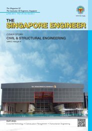
Cover Story<br />
The Pinnacle@Duxton<br />
Over the last 50 years since its<br />
establishment in 1960, the Housing<br />
& Development Board (HDB) has<br />
chalked up an impressive array <strong>of</strong><br />
achievements. Extending the trackrecord<br />
further is the first 50-storey<br />
public housing project in <strong>Singapore</strong>,<br />
which is also, at 168 m, the tallest.<br />
Introduction<br />
The Pinnacle@Duxton comprises 1848<br />
residential units spread over seven<br />
blocks, and one multi-storey carpark. It<br />
is located on a site (Fig 1) on which, in<br />
1963, Blocks 1 and 2 Cantonment Road,<br />
the first two HDB blocks in the area,<br />
were built.<br />
An international architectural<br />
competition was organised by <strong>Singapore</strong>’s<br />
Urban Redevelopment Authority to<br />
obtain the best design ideas for high-rise<br />
living in the city, that would also take<br />
into account the historical significance<br />
<strong>of</strong> the site. The competition was won<br />
by architect Mr Khoo Peng Beng from<br />
ARC Studio Architecture + Urbanism, a<br />
<strong>Singapore</strong>-based firm.<br />
Important features <strong>of</strong> the project<br />
include sky bridges and sky gardens<br />
at the 26 th and 50 th storeys, linking all<br />
the seven blocks, as well as a variety <strong>of</strong><br />
façade elements. The circuit board-like<br />
arrangement <strong>of</strong> bay windows, planters,<br />
and balconies, helps to differentiate The<br />
Pinnacle@Duxton from other ‘regular’<br />
HDB projects (Fig 2).<br />
Project information<br />
Number <strong>of</strong> blocks<br />
and storey<br />
Total number <strong>of</strong><br />
units<br />
Type <strong>of</strong> unit S1<br />
Type <strong>of</strong> unit S2<br />
Facilities<br />
Basement<br />
7 blocks, each 50<br />
storeys high<br />
1,848<br />
1,232 units<br />
(93 m 2 - 97 m 2 )<br />
616 units<br />
(105 m 2 - 108 m 2 )<br />
Carpark below<br />
blocks 1A to 1E<br />
1 st Storey 1 food court,<br />
4 shops, and 1<br />
convenience store<br />
and carpark<br />
2 nd Storey Carpark at Blk 1A,<br />
1B and 1D<br />
3 rd Storey<br />
(Environmental<br />
deck)<br />
26 th Storey<br />
(Active Zone)<br />
50 th Storey<br />
(Contemplative<br />
Zone)<br />
1 childcare centre,<br />
1 education centre,<br />
playground, event<br />
plaza, basketball<br />
court, and pavilion<br />
jogging track, 840<br />
m long<br />
Viewing decks and<br />
themed garden<br />
Fig1: Site layout plan.<br />
Fig 2: Overall view <strong>of</strong> the completed The Pinnacle@Duxton.<br />
10 · THE SINGAPORE ENGINEER Jun 2010
Cover Story<br />
THE SINGAPORE ENGINEER Jun 2010 · 11
Cover Story<br />
Design <strong>of</strong> super-structure and substructure<br />
As The Pinnacle@Duxton was HDB’s<br />
first super high-rise development,<br />
rigorous design analyses were conducted<br />
to ensure structural stability. The<br />
structural system adopted is reinforced<br />
concrete construction coupled with a<br />
beam-column-slab rigid frame for the<br />
building. All column loads are transferred<br />
directly, floor to floor, down to the<br />
foundation. No transfer beams have been<br />
used. The design also responded to the<br />
need for robustness, with the provision<br />
<strong>of</strong> peripheral ties and internal ties, to<br />
ensure that the building is not vulnerable<br />
to progressive collapse.<br />
HDB collaborated with the National<br />
University <strong>of</strong> <strong>Singapore</strong> in the study<br />
<strong>of</strong> lightning protection and for wind<br />
tunnel analysis, during the design stage<br />
<strong>of</strong> the project. Numerous wind tunnel<br />
simulations were also conducted in the<br />
laboratory to analyse the effect <strong>of</strong> wind<br />
currents on the seven tall buildings and<br />
also their environmental impact on the<br />
neighbourhood. In addition, traffic<br />
impact modelling and analysis were also<br />
performed to ensure optimal travelling<br />
times along the two abutting major<br />
roads.<br />
HDB’s own in-house design and<br />
detailing s<strong>of</strong>tware, SE CAD, was used<br />
to model and design the tower blocks.<br />
SE CAD has been developed for highrise<br />
building analysis and design. Key<br />
performance parameters required for<br />
high-rise, reinforced concrete buildings,<br />
were computed automatically by the<br />
s<strong>of</strong>tware.<br />
Powered by a robust, finite element<br />
engine with a built-in precast components<br />
database, and incorporating a userfriendly<br />
interface, SE CAD provided<br />
solutions for tasks ranging from 3D<br />
structural analysis, computation, design,<br />
and detailing, to the production <strong>of</strong><br />
drawings (Fig 3).<br />
As the modelling and analysis process<br />
was fully integrated, feasibility studies<br />
were carried out on various possible<br />
structural configurations, to identify the<br />
most suitable design proposal.<br />
Once the shapes and layouts for the<br />
tall structures were established, their<br />
structural behaviour was simulated<br />
effortlessly. The design and analysis results<br />
(eg for bending moments and shear<br />
forces), structural drawings, and material<br />
quantities, were obtained instantly, once a<br />
building’s super-structure was modelled.<br />
Additional contributions from the SE<br />
CAD s<strong>of</strong>tware included auto-generation<br />
<strong>of</strong> the loading plan, 3D model rendering,<br />
and production <strong>of</strong> shop drawings for<br />
precast components and prefabricated<br />
reinforcements.<br />
For the sub-structure design,<br />
thorough investigations were conducted<br />
around the site, to ascertain the<br />
Fig 3: Typical workfl ow using SE CAD.<br />
properties <strong>of</strong> the soil. The Duxton site<br />
consists primarily <strong>of</strong> hard silty sandstone,<br />
and concrete bored piles have been used<br />
to support the foundation. A total <strong>of</strong><br />
1330 bored piles was designed with an<br />
average pile penetration length <strong>of</strong> 19 m.<br />
Each tower block was designed to sit on<br />
a 2.7 m thick raft foundation supported<br />
by 140 equally spaced bored piles <strong>of</strong> 1.5<br />
m diameter. The raft foundation system<br />
provides structural stability and rigidity<br />
for the high-rise tower block and prevents<br />
differential settlement.<br />
12 · THE SINGAPORE ENGINEER Jun 2010
Cover Story<br />
Precast technology<br />
For The Pinnacle@Duxton, conscientious<br />
efforts were made by the architects and<br />
engineers to make the project buildable,<br />
through the adoption <strong>of</strong> modularisation<br />
and standardisation concepts. The<br />
various options for the standard layouts<br />
(S1 and S2) <strong>of</strong> the units in the residential<br />
blocks, were obtained by configuring<br />
units as mirror images <strong>of</strong> one another<br />
and by rotation <strong>of</strong> these unit plans.<br />
The modularisation <strong>of</strong> the units was<br />
replicated to obtain the block design.<br />
The floor plans for a typical storey<br />
were also repeated for better efficiency<br />
in precast construction. The adoption<br />
<strong>of</strong> modularisation and standardisation<br />
also enabled prefabrication to be costeffective<br />
due to the high repetition <strong>of</strong> the<br />
precast components and prefabricated<br />
reinforcement.<br />
As a result, it was possible to<br />
incorporate a high proportion (about<br />
85% <strong>of</strong> the total volume <strong>of</strong> concrete) <strong>of</strong><br />
precast technology in the construction<br />
<strong>of</strong> the tower blocks. Precast components<br />
were utilised for various elements<br />
including prestressed plank, column,<br />
lift wall, household shelter wall, gable<br />
end wall, façade wall with bay window,<br />
façade wall with planters, façade wall<br />
with balcony, screen wall, refuse chute,<br />
staircase, and parapet.<br />
The use <strong>of</strong> large volumes <strong>of</strong> precast<br />
concrete in the project increased<br />
productivity by about 15%. In addition,<br />
it facilitated construction works in a<br />
tight, built-up, working environment,<br />
and reduced environmental impact on<br />
the existing area. In addition, precast<br />
concrete elements are <strong>of</strong> better quality as<br />
they are produced in a factory-controlled<br />
environment.<br />
To expedite construction works, a<br />
typical floor was divided into two segments<br />
(part A and part B) by a construction<br />
joint (Fig 4). The construction work<br />
was staggered, that is, a team <strong>of</strong> workers<br />
from a construction trade would work<br />
on part A and then move on to part B<br />
without having to stop for workers from<br />
the other trades to complete their tasks.<br />
With this, it was possible to achieve the<br />
anticipated 6-day construction cycle for<br />
each segment <strong>of</strong> a typical floor.<br />
The project team adopted the use <strong>of</strong><br />
large precast facade panels, measuring<br />
about 7 m in length (Fig 5) compared<br />
to the usual length <strong>of</strong> 3 m to 4 m. This<br />
enhanced tower crane utilisation and<br />
improved site productivity. The façades<br />
<strong>of</strong> planter boxes, sun-shaded louvred<br />
windows, and balconies, are arranged in<br />
different combinations, creating a series<br />
<strong>of</strong> vertical, zigzag lines that resemble<br />
Fig 4: Typical fl oor layout showing the construction joint which divides the fl oor into two segments.<br />
Fig 5: Large precast façade panels.<br />
Fig 6: Precast, volumetric hollow-cored wall.<br />
flowing water. In addition, the window<br />
frames were fixed to the facades before<br />
delivery to site. This will eliminate water<br />
seepage through the windows. The wall<br />
panels were designed to be hollow-cored<br />
(Fig 6) so as to reduce the weight <strong>of</strong> the<br />
components and minimise risk during<br />
hoisting and erection.<br />
THE SINGAPORE ENGINEER Jun 2010 · 13
Cover Story<br />
Design and installation <strong>of</strong> sky bridges<br />
The 12 sky bridges, connecting the seven<br />
blocks, at the 26 th and 50 th storeys, form<br />
part <strong>of</strong> outdoor sky gardens which are<br />
equipped with amenities for recreational<br />
purposes. The bridges are made <strong>of</strong> steel<br />
with concrete slabs on top. The lengths<br />
<strong>of</strong> the bridges vary, with the longest<br />
spanning 48 m and weighing 327 t. The<br />
widths and heights <strong>of</strong> the bridges are 20<br />
m and 3.9 m, respectively.<br />
The design <strong>of</strong> the sky bridges was<br />
carried out by T.Y.Lin International<br />
Pte Ltd, HDB’s consultant. The design<br />
adopted a 3-dimensional triangular<br />
truss layout which is stable without<br />
lateral support and could be erected<br />
independently. The bridges are designed<br />
to withstand wind forces in all directions.<br />
The side faces are tapered to reduce<br />
the obstruction to wind flow, thus<br />
minimising the wind pressure on the face.<br />
One end <strong>of</strong> each bridge was designed<br />
to be fixed to the building, to improve<br />
the natural frequency <strong>of</strong> the bridge and<br />
reduce vibrations from walking and<br />
jogging, thus enhancing comfort levels<br />
for people.<br />
Owing to the tight site conditions,<br />
there were many challenges in the<br />
erection <strong>of</strong> the bridges, relating to the<br />
installation method and procedures,<br />
availability <strong>of</strong> space at site, and duration<br />
<strong>of</strong> the installation. Owing to the sizes,<br />
the bridges were fabricated in segments<br />
<strong>of</strong>f-site, at a factory (Fig 7), transported<br />
to the site, and assembled onto the<br />
complete structure. To overcome the<br />
space constraints, the 50 th and 26 th storey<br />
bridges were stacked on top <strong>of</strong> each<br />
other (Fig 8). This also facilitated the<br />
subsequent lifting operation.<br />
In the factory, as well as during the onsite<br />
assembly <strong>of</strong> the sky bridge members,<br />
the fitting up, welding, testing, and trial<br />
assembly <strong>of</strong> the sky bridge trusses were<br />
supervised by an independent checker.<br />
The progress <strong>of</strong> the work was closely<br />
supervised by the Resident <strong>Engineers</strong> and<br />
Resident Technical Officers who were<br />
stationed on-site and at the fabrication<br />
yard.<br />
After fabrication, the sky bridges<br />
were lifted to their respective heights<br />
using the strand jack system which was<br />
used instead <strong>of</strong> cranes, due to the height<br />
<strong>of</strong> the buildings. In addition, this system<br />
Fig. 7: Welding, testing, and trial assembly, <strong>of</strong> sky bridge steel trusses at the factory.<br />
Fig 8: Assembly <strong>of</strong> the sky bridge steel trusses on site. The 50 th and 26 th sky bridges are stacked on top<br />
<strong>of</strong> each other.<br />
allowed the bridges to be assembled at<br />
a lower level before hoisting the whole<br />
assembly, thus enhancing safety on site.<br />
Four strand jacks were required for<br />
each lifting. The jacks were installed<br />
and positioned at four corners between<br />
the two buildings at the 50 th storey ro<strong>of</strong><br />
top position (Fig 9). Prior to the lifting,<br />
a trial jacking was done, that raised the<br />
skybridge 300 mm <strong>of</strong>f the ground, to<br />
ensure that the jacks were functioning<br />
properly.<br />
The bridges are fixed to the core<br />
walls <strong>of</strong> the residential buildings. To fix<br />
the bridges safely and securely to the core<br />
walls, base plates and sleeves for tension<br />
bars were cast together with the core<br />
walls. Great care was taken to ensure that<br />
the cast-in items aligned accurately with<br />
the tower blocks. When the bridges were<br />
lifted to their final positions at the 50 th<br />
and 26 th storeys, and adjusted, the main<br />
trusses were connected to the building by<br />
high strength bars and locked in-place by<br />
casting the concrete slab which forms the<br />
floor <strong>of</strong> the bridge.<br />
14 · THE SINGAPORE ENGINEER Jun 2010
Cover Story<br />
The sky bridge structural system<br />
Main<br />
structure<br />
Diaphragm<br />
Connecting<br />
member to<br />
member<br />
Connection<br />
to building<br />
core wall<br />
Main truss<br />
Three-dimensional steel<br />
truss.<br />
Concrete topping 125 mm<br />
thick.<br />
Full penetration butt weld.<br />
Using Macalloy posttensioned<br />
bars.<br />
Consists <strong>of</strong> 1 top chord<br />
and 2 bottom chords. The<br />
top chord has a 125 mm<br />
thick concrete topping.<br />
The combination acts as a<br />
composite.<br />
The concrete topping at the top deck<br />
level and mezzanine level ties with the<br />
building floor slab and, together with<br />
the tie beam between two core walls, acts<br />
as a diaphragm to resist the lateral and<br />
vertical loads.<br />
PROJECT CREDITS<br />
Client<br />
Housing & Development Board<br />
Project Management<br />
SIPM Consultants<br />
Design Architect<br />
ARC Studio Architecture + Urbanism<br />
Project Architect<br />
RSP Architects Planners & <strong>Engineers</strong><br />
C&S Consultant<br />
Surbana International<br />
Sky Bridge Consultant<br />
T.Y.Lin International<br />
M & E Consultant<br />
Surbana International<br />
Cost Management<br />
Surbana International<br />
Main Contractor<br />
Chip Eng Seng Contractors (1988) Pte<br />
Ltd.<br />
All images by HDB.<br />
Fig 9: Lifting <strong>of</strong> sky bridges to the 50 th storey using the strand jack system.<br />
THE SINGAPORE ENGINEER Jun 2010 · 15
Cover Story<br />
Panoramic view <strong>of</strong> the skyline from the viewing deck.<br />
The Pinnacle@Duxton is the tallest public housing development in <strong>Singapore</strong>.<br />
16 · THE SINGAPORE ENGINEER Jun 2010
RAISE YOUR BUILDING’S ECO-PROFILE<br />
Make your environmental statement, with a BIPV system.<br />
Harvest electricity, straight from the sun.<br />
Reduce your electricity bills, for years to come.<br />
Interested in architectural PV solutions?<br />
Contact Phoenix Solar - <strong>Singapore</strong>’s leading PV system integrator<br />
Phoenix Solar Pte Ltd<br />
209 Syed Alwi Road<br />
<strong>Singapore</strong> 207742<br />
Tel: 65-6511 9339<br />
Fax: 65-6511 9333<br />
info@phoenixsolar.sg<br />
www.phoenixsolar.com/sg<br />
Making energy together
Refreshing the GeoFEA’s User’s Interface<br />
By S.H. Hong, GeoS<strong>of</strong>t Pte Ltd<br />
In this article, we are <strong>of</strong>fering a glimpse at the<br />
user interface in the next version <strong>of</strong> GeoFEA. We<br />
had consolidated some feedbacks from users and<br />
prioritised the wish-list for our prototype.<br />
Introduction<br />
It had been two years since we started this column<br />
in 2008. A sneak into our new graphical user’s<br />
interface will conclude our series <strong>of</strong> articles in “The<br />
<strong>Singapore</strong> Engineer”. Much effort was put in to<br />
raise awareness <strong>of</strong> some key issues in geotechnical<br />
finite element modelling. It is also time for us to<br />
take a break and concentrate our effort on raising<br />
the bar in terms <strong>of</strong> user’s experience. We had made<br />
revamping the Graphical User Interface (GUI) our<br />
priority.<br />
Windows application that was written with<br />
Windows Presentation Foundation (WPF), Figure<br />
1(a) instead <strong>of</strong> Windows Forms, Figure 1(b). WPF<br />
is a graphical subsystem for rendering user<br />
interfaces in Windows-based applications. The core<br />
<strong>of</strong> pre- and post- processor will have to be build<br />
from the ground up, allowing easier development.<br />
GUI things that were previously not possible are<br />
now a possibility.<br />
Figure 2: Buttons for various stages <strong>of</strong> modelling.<br />
The user will be guided by the visible buttons<br />
(Figure 2) on what options are made available at<br />
each stage <strong>of</strong> modelling.<br />
(a)<br />
Workspace and tool panels<br />
Frequently used tool panels are opened by default.<br />
The users will have the freedom to move these<br />
panels from their default positions to a location that<br />
the users are comfortable with (Figure 3).<br />
Alternative placeholders are highlighted as shown<br />
in Figure 3 as arrow in a box ( ).<br />
(b)<br />
Figure 1: GeoFEA’s user interface. (a) Prototype<br />
new look. (b) Old look.<br />
We're considering revamping the GUI to a<br />
Figure 3: Placeholders for docking panels.
Another obvious change is the axes orientation<br />
indicator which is now coloured differently for each<br />
axis and resides on the workspace itself.<br />
GUI buttons<br />
The buttons are made larger with superfluous<br />
buttons removed for a clearer line <strong>of</strong> operation<br />
(Figure 4). For example, in a two-dimensional (2-<br />
D) project, buttons relating to 2-D work space are<br />
shown. The 3-D options are left out to give a<br />
cleaner look. This is a marked improvement from<br />
the previous GUI where the 3-D buttons are simply<br />
deactivated.<br />
You talk, we listen and respond. This change arises<br />
from feedbacks by our current user that the current<br />
interface has too many buttons to start with.<br />
Without proper hints and guidance, the old<br />
interface workflow is perplexing for beginners.<br />
Figure 5: Modified trackball control.<br />
(a)<br />
(b)<br />
Figure 4: Work space buttons. (a) 2D project.<br />
(b) 3D project.<br />
View controls<br />
We had also included easy 3D view change and<br />
intuitive 3 Button Mouse support. The trackball<br />
was modified to give user a better control over the<br />
view angles. Mouse over the view controls will<br />
bring them into focus and dimmed when not in use.<br />
This allows a larger screen estate to be tenanted by<br />
other essential controls.<br />
Maintaining an in-plane view rotation was quite a<br />
task in the old pre- and post-processors. The inplane<br />
rotation is decoupled from the out-<strong>of</strong>-plane<br />
rotation by the implementation <strong>of</strong> a circumferential<br />
ring control (Figure 5). The out-<strong>of</strong>-plane rotation<br />
can be realised by holding down the left mouse<br />
button in the preferred direction within the inner<br />
circular control (Figure 6).<br />
Figure 6: Inner circular control for out-<strong>of</strong>-plane<br />
rotation.<br />
View rotation using the centre mouse button is still<br />
available other than a minor tweak to the sensitivity<br />
level.<br />
A new zoom control was added for users without a<br />
scroll wheel mouse control.<br />
The panning operation, which was well tested by<br />
other computer aided design s<strong>of</strong>tware, was left<br />
largely unchanged by dragging the mouse keeping<br />
its right button depressed.<br />
Attributes <strong>of</strong> a model<br />
We had placed the attributes to a model as the<br />
default dock panel on screen to allow user’s access<br />
to various parameters defining geometry, analysis<br />
data and construction sequence as shown in (Figure<br />
7). The properties for each parameter will be<br />
reflected in another dock panel below the model<br />
attributes docking panel in the default layout.
Figure 9: Dimensions during basic shape creation.<br />
The coordinates <strong>of</strong> the cursor is also shown if the<br />
user is more comfortable with the old version’s way<br />
<strong>of</strong> input.<br />
Figure 7: Dock panel for model attributes.<br />
Stepping through the construction stages<br />
We have also made it easier to cycle through<br />
various construction stages by setting the stage<br />
view control as one <strong>of</strong> the default panels docked at<br />
the bottom right screen estate (Figure 8).<br />
Figure 10: Dimensions during extrusion operation.<br />
In Figure 10, the extrusion dimension from the<br />
basic shape is displayed so that the user can easily<br />
determine the third dimension in a 3-D view.<br />
Figure 8: Construction stage controls<br />
Dimensions indication feature<br />
One new feature that has successfully made its way<br />
into our prototype is the on-screen dimensioning<br />
function. The length and width <strong>of</strong> the rectangle is<br />
displayed on the screen to help user determine its<br />
size for the example shown in Figure 9.<br />
Reporting functions<br />
We hear you! In the pipeline, we are adding a<br />
report generation feature (Figures 11). The report<br />
wizard allows the user to quickly create a new text<br />
report. It includes features for filtering parameters<br />
to output, and also allows the user to easily create<br />
title box containing various information such as the<br />
date, time and page number (Figure 12). We aim to<br />
turn the tedious chore <strong>of</strong> drafting technical reports<br />
into something close to playing a video game.
Figure 11: Tree view <strong>of</strong> report generation user<br />
interface.<br />
Figure 13: Login page prototype for online<br />
engineering portal.<br />
Conclusion<br />
The graphical user interfaces revealed in this article<br />
is a prototype. This prototype will be used as part <strong>of</strong><br />
the s<strong>of</strong>tware design process to allow our engineers<br />
and designers the ability to explore design<br />
alternatives, test theories and confirm performance<br />
prior to our up-coming alpha test version release.<br />
Figure 12: Sample layout <strong>of</strong> image with title block.<br />
Going online<br />
Looking forward, GeoS<strong>of</strong>t is poised to take a giant<br />
leap forward with an exciting project - a dream <strong>of</strong><br />
an internet-based engineering platform on which a<br />
collaborative culture can be developed (Figure 13).<br />
The power <strong>of</strong> the Internet in the “Blue Ocean” is<br />
there for all to tap. This platform will be designed<br />
to facilitate communication, collaboration and<br />
content sharing across networks <strong>of</strong> contacts.<br />
The evolution <strong>of</strong> personal computer technologies<br />
will no doubt opens up exciting possibilities in the<br />
way engineers conduct finite element analyses.<br />
With the Internet no longer constrained by slow<br />
connections and computer processors and high<br />
costs for storage, it is time to rethink and revamp<br />
the way construction industry embraces these new<br />
technologies in terms <strong>of</strong> engineering services.<br />
S<strong>of</strong>tware should routinely be designed to make it<br />
easy for people to do what works and difficult to do<br />
what doesn’t. One important and powerful way that<br />
s<strong>of</strong>tware products can do this is through welldesigned<br />
defaults. Given the power <strong>of</strong> defaults, our<br />
designers could use them to nudge people in a<br />
direction that will enhance their work efficiency.<br />
According to Porter 2001, the greatest impact <strong>of</strong> the<br />
Internet is to enable the reconfiguration <strong>of</strong> existing<br />
industries that had been constrained by high cost<br />
for communicating, gathering information and<br />
accomplishing transactions. By integrating the<br />
internet into our overall strategy, GeoFEA will<br />
realise its potential as a powerful engineering tool.<br />
Reference<br />
Michael E. Porter. "Strategy and the Internet”,<br />
Harvard Business Review, Vol. 79, No. 3, March<br />
2001.<br />
About GeoS<strong>of</strong>t Pte Ltd<br />
GeoS<strong>of</strong>t Pte Ltd is registered in <strong>Singapore</strong>. GeoS<strong>of</strong>t<br />
focuses singularly on geotechnical products with<br />
unparalleled developments. We are the leader in the<br />
FEM mesh generation and solver technologies<br />
implemented on desktop PC platform.
Structural Engineering<br />
The design <strong>of</strong> Burj Khalifa Tower – the world’s<br />
tallest structure<br />
The objective in creating this building,<br />
besides setting a record, is to embody<br />
the highest aspirations <strong>of</strong> mankind.<br />
Such a project goal, by necessity,<br />
requires pushing current analysis, as<br />
well as materials and construction<br />
technologies, to literally new heights.<br />
However, as building to such a height<br />
had never been attempted before, it<br />
was also necessary to ensure that all<br />
technologies and methods utilised are<br />
<strong>of</strong> sound development and practice.<br />
Mr William F Baker, Partner,<br />
Mr James J Pawlikowski, Associate<br />
Director, and Mr Bradley S Young,<br />
Associate, from Skidmore, Owings &<br />
Merrill LLP (SOM), Chicago, Ilinois,<br />
USA, explain how the designers sought<br />
to use conventional systems, materials,<br />
and construction methods, modified<br />
and utilised in new capacities, to achieve<br />
this l<strong>of</strong>ty goal.<br />
Introduction<br />
The tower (Fig 1) opened to much fanfare<br />
on 4 January 2010 and was re-christened<br />
Burj Khalifa (it was previously known as<br />
Burj Dubai). Rising to a height <strong>of</strong> 828 m<br />
and with over 160 storeys, it is the world’s<br />
tallest building and the tallest man-made<br />
structure ever built.<br />
The Burj Khalifa Tower is the<br />
centrepiece <strong>of</strong> a US$ 20 billion<br />
development located just outside <strong>of</strong><br />
downtown Dubai. The project consists<br />
<strong>of</strong> the tower itself, as well as an adjacent<br />
podium structure, a separate 12-storey<br />
<strong>of</strong>fice annexe, a two-storey pool annexe,<br />
and four levels <strong>of</strong> sub-grade parking<br />
under the site. The 280,000 m 2 reinforced<br />
concrete multi-use tower comprises<br />
predominantly residential and <strong>of</strong>fice units,<br />
and it also houses retail establishments<br />
and a Giorgio Armani Hotel. Together,<br />
the tower and podium structures have a<br />
combined area <strong>of</strong> 465,000 m 2 .<br />
From the outset, the intention was<br />
to make Burj Khalifa the world’s tallest<br />
building (Fig 2 presents the world’s 10<br />
tallest buildings). The <strong>of</strong>ficial arbiter on<br />
heights is the Council on Tall Buildings and<br />
Urban Habitat (CTBUH). The CTBUH<br />
Fig 1: The Burj Khalifa Tower.<br />
22 · THE SINGAPORE ENGINEER Jun 2010
Structural Engineering<br />
Fig 2: Lineup <strong>of</strong> the world’s 10 tallest buildings.<br />
measures the heights <strong>of</strong> buildings using<br />
three criteria. Table 1 compares the values<br />
for Burj Khalifa with the corresponding<br />
values for the previous record holders.<br />
Architectural design<br />
The primary design concept for the tower<br />
took the form <strong>of</strong> an indigenous desert<br />
flower. The organic form, with tri-axial<br />
geometry and spiralling growth, can be<br />
easily seen in the final design.<br />
Additionally, traditional Islamic forms<br />
were utilised to enrich the tower’s design,<br />
and to incorporate visual references to the<br />
culture and history <strong>of</strong> the surrounding<br />
region. The floor plan has a tri-axial,<br />
Y-shaped configuration, formed by three<br />
separate wings connected to a central core<br />
(Fig 3). As the tower rises, one wing at<br />
each tier sets back in a spiralling pattern,<br />
further emphasising its height (Fig 4). The<br />
Y-shaped plan is ideal for residential and<br />
hotel usage, in that it allows the maximum<br />
views outward, without overlooking a<br />
neighbouring unit. The wings contain the<br />
residential units and hotel guest rooms,<br />
with the central core housing all <strong>of</strong> the<br />
elevatoring and mechanical closets.<br />
Additionally, the tower is serviced by<br />
five separate mechanical zones, located<br />
approximately 30 floors apart, over the<br />
height <strong>of</strong> the building. Located above the<br />
occupied reinforced concrete portion <strong>of</strong><br />
the building is the structural steel spire,<br />
housing communication and mechanical<br />
floors, completing the architectural form<br />
<strong>of</strong> the tower. The architects and engineers<br />
worked closely together from the<br />
beginning <strong>of</strong> the project to determine the<br />
shape <strong>of</strong> the tower, in order to provide an<br />
efficient building in terms <strong>of</strong> its structural<br />
system and in its response to wind, while<br />
still maintaining the integrity <strong>of</strong> the initial<br />
design concept.<br />
Structural system description<br />
In addition to its aesthetic and functional<br />
advantages, the spiralling Y-shaped plan<br />
was also utilised to shape the building,<br />
to reduce the wind forces on the tower,<br />
as well as to keep the structure simple,<br />
and foster constructability. The structural<br />
system can be described as a ‘buttressed’<br />
core, and consists <strong>of</strong> high-performance<br />
concrete wall construction.<br />
Each <strong>of</strong> the wings buttresses the others<br />
via a 6-sided central core or hexagonal hub.<br />
This central core provides the torsional<br />
resistance <strong>of</strong> the structure, similar to that<br />
Fig 3: Typical fl oor plan.<br />
for a closed pipe or axle. Corridor walls<br />
extend from the central core to near the<br />
end <strong>of</strong> each wing, terminating in thickened<br />
hammer-head walls. These corridor walls<br />
and hammer-head walls are similar to the<br />
webs and flanges <strong>of</strong> a beam in the way they<br />
resist wind shears and moments. Perimeter<br />
columns and flat plate floor construction<br />
complete the system. At mechanical<br />
Height to Architectural Top 828 m (Burj Khalifa) 508 m (Taipei 101)<br />
Highest Occupied Floor 535 m (Burj Khalifa) 474 m (Shanghai<br />
World Financial Center)<br />
Height to Tip 830 m (Burj Khalifa) 527 m (Sears Tower)<br />
Table 1: Comparison <strong>of</strong> height values for Burj Khalifa and those for previous record holders.<br />
THE SINGAPORE ENGINEER Jun 2010 · 23
Structural Engineering<br />
floors, outrigger walls are provided to link<br />
the perimeter columns to the interior wall<br />
system, allowing the perimeter columns<br />
to participate in the lateral load resistance<br />
<strong>of</strong> the structure. Hence, all <strong>of</strong> the vertical<br />
concrete is utilised to support both gravity<br />
and lateral loads. The result is a tower that<br />
is extremely stiff laterally and torsionally.<br />
It is also a very efficient structure in that<br />
the gravity load resisting system has<br />
been utilised so as to maximise its use in<br />
resisting lateral loads.<br />
As the building spirals in height, the<br />
wings set back to provide many different<br />
floor plates. The setbacks are organised<br />
with the tower’s grid, such that the<br />
building stepping is accomplished by<br />
aligning columns above with walls below,<br />
to provide a smooth load path. As such,<br />
the tower does not contain any structural<br />
transfers. These setbacks also have the<br />
advantage <strong>of</strong> providing a different width<br />
to the tower for each differing floor plate.<br />
This stepping and shaping <strong>of</strong> the tower<br />
has the effect <strong>of</strong> ‘confusing the wind’<br />
- wind vortices never get organised over<br />
the height <strong>of</strong> the building because at each<br />
new tier, the wind encounters a different<br />
building shape.<br />
Fig 4: Tower perspective.<br />
Structural analysis and superstructure<br />
design<br />
The reinforced concrete structure<br />
was designed in accordance with the<br />
requirements <strong>of</strong> ACI 318-02 Building<br />
Code Requirements for Structural<br />
Concrete. Wall and column concrete<br />
strengths range from C80 to C60 cube<br />
strength, and utilise Portland cement,<br />
fly ash, and local aggregates. The C80<br />
concrete has a maximum specified<br />
Young’s Elastic Modulus <strong>of</strong> 43,800 N/<br />
mm 2 at 90 days. Wall and column sizes<br />
were optimised using virtual work /<br />
LaGrange multiplier methods, resulting<br />
in a very efficient structure. Wall thickness<br />
and column sizes were also fine-tuned to<br />
reduce the effects <strong>of</strong> creep and shrinkage<br />
on the structure. To reduce the effects<br />
<strong>of</strong> differential column shortening due to<br />
creep between the perimeter columns and<br />
interior walls, the perimeter columns were<br />
sized such that the self-weight gravity<br />
stress on the perimeter columns was equal<br />
to the stress on the interior corridor walls.<br />
The outriggers at the five mechanical floors<br />
tie all the vertical load carrying elements<br />
24 · THE SINGAPORE ENGINEER Jun 2010
Structural Engineering<br />
together, further ensuring uniform<br />
gravity stress by essentially allowing the<br />
structure to redistribute gravity loads<br />
at five locations along the building’s<br />
height, thereby reducing differential creep<br />
movements. Additionally, the perimeter<br />
columns and corridor walls were given<br />
matching thicknesses, providing them<br />
with similar volume to surface ratios, to<br />
minimise differential shortening due to<br />
concrete shrinkage.<br />
The majority <strong>of</strong> the tower is a<br />
reinforced concrete structure. However,<br />
the top <strong>of</strong> the tower consists <strong>of</strong> a structural<br />
steel spire utilising a diagonally braced<br />
lateral system. The spire, which houses<br />
several mechanical and communication<br />
floors, and open void space, culminates<br />
in a pinnacle element. The structural<br />
steel spire was designed for gravity, wind,<br />
seismic loads, and fatigue, in accordance<br />
with the requirements <strong>of</strong> AISC Load and<br />
Resistance Factor Design Specification for<br />
Structural Steel Buildings (1999).<br />
The entire building structure was<br />
analysed for gravity (this included the<br />
performance <strong>of</strong> P-Delta analysis), wind,<br />
and seismic loadings, utilising ETABS<br />
version 8.4 (Fig 5). The three-dimensional<br />
analysis model consisted <strong>of</strong> the reinforced<br />
concrete walls, link beams, slabs, raft,<br />
piles, and the spire’s structural steel<br />
system. The full analysis model consisted<br />
<strong>of</strong> over 73,500 shells and 75,000 nodes.<br />
Under lateral wind loading, the building<br />
deflections were well below commonly<br />
used criteria. The dynamic analysis<br />
indicated that the first mode is lateral<br />
side-sway with a period <strong>of</strong> 11.3 seconds.<br />
The second mode is a perpendicular lateral<br />
side-sway with a period <strong>of</strong> 10.2 seconds.<br />
Torsion is the fifth mode with a period <strong>of</strong><br />
4.3 seconds.<br />
The Dubai Municipality specifies<br />
Dubai as a UBC97 Zone 2a seismic region<br />
(with a seismic zone factor Z = 0.15 and<br />
soil pr<strong>of</strong>ile Sc). The seismic analysis<br />
consisted <strong>of</strong> a site-specific response spectra<br />
analysis. Seismic loading typically did<br />
not govern the design <strong>of</strong> the reinforced<br />
concrete tower structure. However,<br />
seismic loading did govern the design <strong>of</strong><br />
the reinforced concrete podium buildings<br />
and the tower’s structural steel spire. Sitespecific<br />
seismic reports were developed<br />
for the project, including a seismic hazard<br />
analysis. The potential for liquefaction<br />
was investigated, based on several<br />
accepted methods. It was determined that<br />
liquefaction is not considered to have any<br />
structural implications for the deep-seated<br />
tower foundations.<br />
A comprehensive construction<br />
sequence analysis incorporating the effects<br />
<strong>of</strong> creep and shrinkage was performed to<br />
study the time-dependent behaviour <strong>of</strong><br />
the structure (Fig 6).<br />
Since the vertical concrete elements<br />
tend to have similar compression stress,<br />
the building performs well under the<br />
effects <strong>of</strong> creep and shrinkage. The results<br />
<strong>of</strong> this analysis were utilised to determine<br />
the horizontal and vertical compensation<br />
programmes. For horizontal compensation,<br />
the building is ‘re-centred’ with each<br />
successive centre core jump, correcting for<br />
gravity-induced side-sway effects which<br />
occur up to the casting <strong>of</strong> each storey.<br />
For vertical compensation, additional<br />
Fig 5: Three-dimensional analysis model dynamic mode shapes.<br />
Fig 6: Construction sequence analysis.<br />
height was added by increasing floorto-floor<br />
height, <strong>of</strong>fsetting the predicted<br />
vertical shortening <strong>of</strong> the column and wall<br />
elements.<br />
Wind engineering approach<br />
An extensive programme <strong>of</strong> wind tunnel<br />
tests and other studies was undertaken<br />
in RWDI’s 2.4 m x 1.9 m, and 4.9 m x<br />
2.4 m boundary layer wind tunnels in<br />
Guelph, Ontario, Canada. The wind<br />
tunnel testing programme included rigidmodel<br />
force balance tests, a full aeroelastic<br />
model study, cladding pressure studies,<br />
and pedestrian wind environment studies<br />
(Figs 7 and 8). These studies used models<br />
mostly at 1:500 scale. However, the<br />
pedestrian wind studies utilised a larger<br />
scale <strong>of</strong> 1:250 for the development <strong>of</strong><br />
aerodynamic solutions aimed at reducing<br />
wind speeds. Wind statistics played an<br />
important role in relating the predicted<br />
THE SINGAPORE ENGINEER Jun 2010 · 25
Structural Engineering<br />
levels <strong>of</strong> response to return period.<br />
Extensive use was made <strong>of</strong> groundbased<br />
wind data, balloon data, and<br />
computer simulations employing regional<br />
atmospheric modelling techniques, in<br />
order to establish the wind regime at the<br />
upper levels.<br />
To determine the wind loading on the<br />
main structure, wind tunnel tests were<br />
undertaken early in the design, using the<br />
high-frequency-force-balance technique.<br />
The wind tunnel data were then combined<br />
with the dynamic properties <strong>of</strong> the tower,<br />
in order to compute the tower’s dynamic<br />
response and the overall effective wind<br />
force distributions at full scale. For Burj<br />
Khalifa, the results <strong>of</strong> the force balance<br />
tests were used as early input for the<br />
structural design and allowed parametric<br />
studies to be undertaken on the effects<br />
<strong>of</strong> varying the tower’s stiffness and mass<br />
distribution.<br />
The building has essentially six<br />
important wind directions (Fig 9). Three<br />
<strong>of</strong> the directions are defined by the wind<br />
blowing directly into a wing. The wind<br />
blows into the ‘nose’ <strong>of</strong> each wing (Nose<br />
A, Nose B, and Nose C), creating the cutwater<br />
effect. The other three directions are<br />
defined by the wind blowing in between<br />
two wings, in the ‘tail’ directions (Tail A,<br />
Tail B, and Tail C). It was noticed that the<br />
force spectra for different wind directions<br />
showed less excitation in the important<br />
frequency range for winds impacting the<br />
pointed or nose end <strong>of</strong> a wing than from<br />
the opposite direction (tail). This was kept<br />
in mind when selecting the orientation <strong>of</strong><br />
the tower relative to the most frequent,<br />
strong wind directions for Dubai –<br />
northwest, south, and east.<br />
Several rounds <strong>of</strong> force balance tests<br />
were undertaken as the geometry <strong>of</strong><br />
the tower evolved, and as the tower was<br />
refined architecturally. The three wings<br />
are set back in a clockwise sequence with<br />
the ‘A’ wing setting back first. After each<br />
Fig 9: Plan view <strong>of</strong> tower.<br />
round <strong>of</strong> wind tunnel testing, the data was<br />
analysed and the building was reshaped to<br />
minimise wind effects and accommodate<br />
unrelated changes in the client’s<br />
programme. In general, the number and<br />
spacing <strong>of</strong> the setbacks changed as did<br />
the shape <strong>of</strong> wings. This process resulted<br />
in a substantial reduction in wind forces<br />
on the tower by ‘confusing’ the wind, by<br />
encouraging disorganised vortex shedding<br />
over the height <strong>of</strong> the tower (Fig 10).<br />
Towards the end <strong>of</strong> design, more<br />
accurate aeroelastic model tests were<br />
Fig 7: Aeroelastic wind tunnel model.<br />
Fig 8: Cladding wind tunnel model.<br />
Fig 10: Tower wind behaviour.<br />
26 · THE SINGAPORE ENGINEER Jun 2010
Structural Engineering<br />
initiated. An aeroelastic model is flexible<br />
in the same manner as the real building,<br />
with properly scaled stiffness, mass, and<br />
damping. The aeroelastic tests were able to<br />
model several <strong>of</strong> the higher translational<br />
modes <strong>of</strong> vibration. These higher modes<br />
dominated the structural response and<br />
design <strong>of</strong> the tower except at the very base<br />
where the fundamental modes controlled.<br />
Based on these results, the predicted<br />
building motions are within the ISO<br />
standard recommended values – there is<br />
no need for auxiliary damping.<br />
Tower foundations<br />
The tower is founded on a pile-supported<br />
raft foundation (Fig 11). The solid<br />
reinforced concrete raft is 3.7 m thick and<br />
was poured utilising 12,500 m 3 <strong>of</strong> C50<br />
(cube strength) self-consolidating concrete<br />
(SCC). The raft was constructed in four<br />
separate pours (for the three wings and the<br />
centre core). Each raft pour occurred over<br />
at least a 24-hour period. Reinforcement<br />
Fig 11: Tower raft under construction.<br />
was typically spaced at 300 mm in the<br />
raft, and arranged such that every 10 th bar<br />
in each direction was omitted, resulting<br />
in a series <strong>of</strong> ‘pour enhancement strips’<br />
throughout the raft. The intersections <strong>of</strong><br />
these strips created 600 mm x 600 mm<br />
openings at regular intervals, facilitating<br />
access and concrete placement.<br />
Owing to the thickness <strong>of</strong> the tower<br />
raft, limiting the peak and differential<br />
temperatures due to the heat <strong>of</strong> hydration<br />
was an important consideration in<br />
determining the raft concrete mix design<br />
and placement methods. The 50 MPa raft<br />
mix incorporated 40% fly ash and a watercement<br />
ratio <strong>of</strong> 0.34. The concrete mix<br />
was poured into large-scale test cubes with<br />
3.7 m side dimensions, prior to the raft<br />
construction, so as to verify the concrete<br />
placement procedures and monitor the<br />
concrete temperature performance.<br />
The tower raft is supported by 194<br />
bored, cast-in-place piles. The piles are<br />
1.5 m in diameter and approximately 43<br />
m long, with a capacity <strong>of</strong> 3,000 t each<br />
(the pile load is tested to 6000 tonnes).<br />
The diameter and length <strong>of</strong> the piles<br />
represent the largest and longest piles<br />
conventionally available in the region.<br />
Additionally, the 6000 tonne pile load<br />
test represented the largest magnitude pile<br />
load test performed to date within the<br />
region (Fig 12). The C60 (cube strength)<br />
SCC concrete was placed by the tremie<br />
method utilising polymer slurry. When the<br />
rebar cage was placed in the piles, special<br />
attention was paid to orient the rebar cage<br />
such that the raft bottom rebar could be<br />
threaded through the numerous pile rebar<br />
cages without interruption, which greatly<br />
simplified the raft construction.<br />
Another design challenge in the<br />
project arose from the existing site<br />
conditions. The ground water, which is<br />
quite high at approximately 2 m below<br />
the surface, is extremely corrosive,<br />
containing approximately three times<br />
the sulphates and chlorides present in sea<br />
water. As such, a rigorous programme <strong>of</strong><br />
anti-corrosion measures was followed<br />
to ensure the long-term integrity <strong>of</strong> the<br />
tower’s foundation system. Measures<br />
instituted included the implementation<br />
<strong>of</strong> specialised waterpro<strong>of</strong>ing systems<br />
and increased concrete cover for the<br />
reinforcement, addition <strong>of</strong> corrosion<br />
inhibitors to the concrete mix, applying<br />
stringent crack control raft design<br />
criteria, and the implementation <strong>of</strong> an<br />
impressed current cathodic protection<br />
system utilising titanium mesh (Fig13).<br />
Additionally, a controlled permeability<br />
formwork liner was utilised for the tower<br />
raft, which resulted in a higher strength /<br />
lower permeability concrete cover for the<br />
rebar. The concrete mix for the piles was<br />
also enhanced. It was designed as a fully<br />
self-consolidating concrete to limit the<br />
possibility <strong>of</strong> defects during construction.<br />
Fig 12: Tower pile load test.<br />
Fig 13: Cathodic protection below raft.<br />
THE SINGAPORE ENGINEER Jun 2010 · 27
Structural Engineering<br />
Tower construction methods<br />
The Burj Khalifa Tower utilised the latest<br />
advancements in construction techniques<br />
and materials technology. The walls were<br />
formed using Doka’s SKE 100 automatic<br />
self-climbing formwork system.<br />
The circular nose columns were<br />
formed with circular steel forms, and<br />
the floor slabs were poured on MevaDec<br />
panel formwork.<br />
Wall reinforcement was prefabricated<br />
on the ground in 8 m sections to allow<br />
for fast placement. Three primary tower<br />
cranes were located adjacent to the central<br />
core, with each continuing to various<br />
heights as required. High-speed, highcapacity<br />
construction hoists were utilised<br />
to transport workers and materials to<br />
the required heights. A specialised GPS<br />
monitoring system was developed to<br />
monitor the verticality <strong>of</strong> the structure,<br />
due to the limitations <strong>of</strong> conventional<br />
surveying techniques.<br />
The construction sequence for the<br />
structure had the central core and slabs<br />
being cast first, in three sections. The<br />
wing walls and slabs followed behind,<br />
and the wing nose columns and slabs<br />
followed behind these (Fig 14). Concrete<br />
was distributed to each wing utilising<br />
concrete booms which were attached to<br />
the jump form system.<br />
One <strong>of</strong> the most challenging<br />
construction issues was ensuring the<br />
pumpability <strong>of</strong> the tower concrete to<br />
reach the world record heights <strong>of</strong> the<br />
tower, which necessitated that concrete be<br />
pumped well over 600 m in a single stage.<br />
High performance concrete is utilised for<br />
the tower, with high modullus concrete<br />
specified for the columns and walls. The<br />
concrete mix was designed to provide low<br />
permeability / high durability concrete.<br />
A horizontal pumping trial was<br />
conducted prior to the start <strong>of</strong> the<br />
superstructure construction in order to<br />
ensure the pumpability <strong>of</strong> the concrete<br />
mixes (Fig 15). This trial involved the use<br />
<strong>of</strong> a long pipe with several 180 0 bends to<br />
simulate the pressure loss in pumping to<br />
heights over 600 m in a single stage.<br />
The final pumping system utilised<br />
on-site Putzmeister pumps, including<br />
two <strong>of</strong> the largest in the world, capable<br />
<strong>of</strong> reaching concrete pumping pressures<br />
up to 350 bars through a high pressure<br />
150 mm pipeline.<br />
Fig 14: Tower construction sequence.<br />
28 · THE SINGAPORE ENGINEER Jun 2010
Structural Engineering<br />
Conclusion<br />
The Burj Khalifa Tower has claimed the<br />
title <strong>of</strong> the world’s tallest structure. It is<br />
an example <strong>of</strong> a successful collaboration<br />
between the requirements <strong>of</strong> structural<br />
systems, wind engineering, and<br />
architectural aesthetics and function. The<br />
tower represents a significant achievement<br />
in terms <strong>of</strong> utilising the latest design,<br />
materials and construction technology,<br />
and methods, in order to provide an<br />
efficient, rational structure, that rises to<br />
heights never seen before.<br />
REFERENCES<br />
Baker W F, Pawlikowski J J, & Young B S:<br />
‘The Challenges in Designing the World’s<br />
Tallest Structure: The Burj Dubai Tower’.<br />
Proceedings <strong>of</strong> the SEI/ASCE Structures<br />
Congress, 2009.<br />
All images by SOM.<br />
PROJECT CREDITS<br />
Owner<br />
Emaar Properties PJSC, Dubai<br />
Project Manager<br />
Turner Construction International<br />
Architect / Structural <strong>Engineers</strong> / MEP<br />
<strong>Engineers</strong><br />
Skidmore, Owings & Merrill LLP<br />
Adopting Architect & Engineer / Field<br />
Supervision<br />
Hyder Consulting Ltd<br />
General Contractor<br />
Samsung / BeSix / Arabtec<br />
Foundation Contractor<br />
NASA Multiplex<br />
Fig 15: Concrete pumping system test.<br />
THE SINGAPORE ENGINEER Jun 2010 · 29
Interview<br />
Engineering urban transformation<br />
Arup brings<br />
t o g e t h e r<br />
individuals from<br />
a wide range <strong>of</strong><br />
disciplines and<br />
encourages them<br />
to look beyond<br />
the constraints<br />
<strong>of</strong> their own<br />
Mr André Lovatt. specialisations,<br />
so that the<br />
engineering consultancy can influence<br />
the future <strong>of</strong> the built environment in a<br />
distinctive manner.<br />
Mr André Lovatt, Principal and<br />
Office Leader, <strong>Singapore</strong>, Arup<br />
<strong>Singapore</strong> Pte Ltd, highlights the<br />
factors underpinning the firm’s<br />
impressive track record in the republic,<br />
in this interview with ‘The <strong>Singapore</strong><br />
Engineer’.<br />
Q: What makes Arup different from<br />
other firms?<br />
A: One <strong>of</strong> the things that makes us<br />
different is how Arup is owned. The<br />
firm is owned in trust on behalf <strong>of</strong> its<br />
staff. The result is an independence <strong>of</strong><br />
spirit that enables us to take long-term<br />
decisions and chart unconventional<br />
routes. This is reflected in the firm’s work,<br />
and in its dedicated pursuit <strong>of</strong> technical<br />
excellence.<br />
One good way to think <strong>of</strong> Arup is as<br />
an ‘idea factory’. Our ability to generate<br />
great ideas is entirely vested within our<br />
people. As a result, we take a great deal <strong>of</strong><br />
care to select the best possible people and<br />
to give them the freedom to do the sort<br />
<strong>of</strong> work they like and are good at.<br />
Q: How is Arup responding to<br />
developments in the construction<br />
industry in <strong>Singapore</strong>?<br />
A: In terms <strong>of</strong> growth, Asia will continue<br />
to have huge prospects and opportunities<br />
and Arup has <strong>of</strong>fices in key Asian cities<br />
such as Hong Kong, Shanghai, Beijing,<br />
Tokyo and <strong>Singapore</strong> to meet these<br />
demands.<br />
In <strong>Singapore</strong>, with over 200 local staff,<br />
Arup is well-placed within the booming<br />
pr<strong>of</strong>essional services sector and we work<br />
on a wide range <strong>of</strong> commercial and<br />
residential building, and infrastructure<br />
projects.<br />
Q: What are some <strong>of</strong> the landmark<br />
projects in <strong>Singapore</strong> that Arup has<br />
been involved in recently?<br />
A: Arup has made significant contributions<br />
to three major developments that have<br />
shaped Marina Bay, <strong>Singapore</strong>’s premier<br />
waterfront destination. They are the<br />
<strong>Singapore</strong> Flyer which, at a height <strong>of</strong><br />
165 m, is the world’s largest Giant<br />
Observation Wheel; Marina Bay Sands<br />
Integrated Resort which <strong>of</strong>fers a 2560-<br />
room luxury hotel, advanced convention<br />
and exhibition facilities, shopping mall,<br />
restaurants, and theatres; and The Helix,<br />
a 280 m bridge, inspired by the shape <strong>of</strong><br />
a DNA molecule.<br />
Arup provided consultancy for the<br />
Downtown Mass Rapid Transit (MRT)<br />
line that connects Marina Bay with the<br />
city centre and we are also a member<br />
<strong>of</strong> the team that will be responsible for<br />
delivering a second footbridge that will<br />
complete the pedestrian route around<br />
the bay.<br />
Arup <strong>Singapore</strong>: overview <strong>of</strong> skills<br />
• Acoustics, Audiovisual and<br />
Theatre Consulting<br />
• Building Services / M&E<br />
• Building Structures<br />
• Environmentally Sustainable<br />
Design (ESD)<br />
• Facade<br />
• Fire<br />
• Geotechnics<br />
• Green Mark / LEED Consulting<br />
• Infrastructure<br />
• IT and Communications<br />
• Maritime<br />
• Programme and Project<br />
Management<br />
• Risk and Security<br />
• Specialist Lighting<br />
• Traffic and Transport Planning<br />
• Tunnelling<br />
• Urban Design<br />
• Vertical Transportation<br />
The iconic <strong>Singapore</strong> Flyer. Image by <strong>Singapore</strong> Flyer Pte Ltd.<br />
30 · THE SINGAPORE ENGINEER Jun 2010
Interview<br />
Arup’s rail engineering capability<br />
is allowing us to assist <strong>Singapore</strong> in<br />
meeting its vision <strong>of</strong> developing a worldclass<br />
transportation system, particularly<br />
the Downtown MRT Line project where<br />
we have provided a range <strong>of</strong> services from<br />
alignment and routing studies to detailed<br />
engineering design.<br />
Q: How is Arup approaching the issue<br />
<strong>of</strong> sustainability?<br />
A: In the early 1970s, Sir Ove Arup, our<br />
founder, was one <strong>of</strong> the first people to<br />
talk <strong>of</strong> ‘sustainability’. So, sustainability<br />
is not new to Arup.<br />
Our design teams are working<br />
together to investigate ways to reduce<br />
energy demands. Through careful<br />
design <strong>of</strong> the facades for projects like<br />
the National Library, One George Street<br />
and 20 Anson, solar thermal loads on<br />
the building are minimised by reducing<br />
the cooling needed from airconditioning<br />
systems. Carefully positioned sunshades<br />
project natural daylight into the spaces<br />
within the building, thus saving electricity<br />
to run artificial lights.<br />
However, the greatest energy<br />
savings would come from avoiding<br />
airconditioning altogether. This is cleverly<br />
achieved by permitting the passage <strong>of</strong><br />
natural breezes for the integrated civic,<br />
cultural, retail and entertainment hub<br />
(CCRC) and by providing assisted<br />
ventilation and heat-reflecting canopies<br />
for Clarke Quay’s streetscape.<br />
As the <strong>Singapore</strong> and other Asian<br />
property markets become more mature<br />
and sophisticated, increasingly the life <strong>of</strong><br />
commercial buildings is being extended<br />
Arup <strong>Singapore</strong> Pte Ltd<br />
Arup opened its <strong>Singapore</strong> <strong>of</strong>fice in<br />
1968. Over the years, the firm has<br />
made significant contributions to<br />
landmark projects such as OCBC<br />
Centre, UOB Plaza, Temasek Towers,<br />
Expo MRT station, <strong>Singapore</strong> Expo,<br />
and the National Library Building.<br />
The company’s other projects in<br />
<strong>Singapore</strong> include the <strong>Singapore</strong> Flyer,<br />
Fusionopolis, ION Orchard, Marina<br />
Bay Sands Integrated Resort, The Helix<br />
bridge, Gardens by the Bay, <strong>Singapore</strong><br />
Sports Hub, School <strong>of</strong> the Arts, and<br />
the renovation <strong>of</strong> Victoria Theatre and<br />
Victoria Concert Hall.<br />
Arup<br />
Founded by Sir Ove Arup in 1946,<br />
by retr<strong>of</strong>itting and refurbishment. The<br />
Green Building agenda, along with<br />
a tighter financial environment will<br />
increase this trend.<br />
Arup has studied the factors that<br />
influence client decisions, and have<br />
recently worked with the BCA to prepare<br />
a guide book targetted at owners’ existing<br />
buildings as part <strong>of</strong> their Green Building<br />
Guide Platinum Series.<br />
with an initial focus on structural<br />
engineering, Arup has become a<br />
global design, engineering, and<br />
business consultancy, with a staff <strong>of</strong><br />
over 10,000 spread over 92 <strong>of</strong>fices in<br />
37 countries.<br />
The firm first came into prominence<br />
with the structural design for the<br />
Sydney Opera House in Australia,<br />
followed by its work on the Centre<br />
Pompidou in Paris, France. Arup has<br />
since grown into a multidisciplinary<br />
organisation. Most recently, the firm’s<br />
contributions to the 2008 Olympics<br />
facilities in Beijing, China, particularly<br />
the National Aquatics Center (Water<br />
Cube) and the Beijing National<br />
Stadium (Bird’s Nest), have served to<br />
reaffirm its reputation.<br />
On the right <strong>of</strong> the picture, The Helix is set against the backdrop <strong>of</strong> the Marina Bay Sands Integrated Resort. Image by Darren Soh.<br />
THE SINGAPORE ENGINEER Jun 2010 · 31
Products & Services<br />
Paving ahead for growing population ‘down<br />
under’<br />
In 1970, Perth in Western Australia had a<br />
population <strong>of</strong> just 700,000 and a footprint<br />
<strong>of</strong> approximately 500 km 2 . Today the<br />
population has increased to 1.9 million<br />
and the metropolitan area is more than<br />
twice the size.<br />
Developers are filling in the few<br />
remaining plots <strong>of</strong> land, stretching along a<br />
north to south coastal corridor, to provide<br />
housing for the ever increasing population,<br />
led by today’s new immigrants.<br />
Predictions are that the population<br />
will double to 3.8 million over the next<br />
40 years, meaning that the city will stretch<br />
from Lancelin in the north, to a point<br />
between Mandurah and Bunbury in the<br />
south – covering more than 10 times the<br />
surface area it covered in 1970.<br />
Western Australia asphalt specialist<br />
BGC Asphalt, is fully utilising a Dynapac<br />
F6-4W paver, laying roads in the last few<br />
remaining sub-divisions <strong>of</strong> Ridge Wood<br />
in Brighton, the latest northern suburb <strong>of</strong><br />
Perth.<br />
BGC’s latest contract, sub-contracted<br />
by earthmoving specialist R J Vincent,<br />
features the laying <strong>of</strong> 6000 m 2 <strong>of</strong> asphalt<br />
over three days. A 40 mm base coarse<br />
with 14 mm aggregate will be topped by a<br />
25 mm wearing coarse – both sitting on a<br />
200 mm limestone sub-base.<br />
Backing up the Dynapac paver is<br />
a CP142 pneumatic tyred roller and a<br />
CC142 twin drum compaction roller.<br />
Across the sub-division, roads are generally<br />
5.5 m wide, <strong>of</strong>ten with 2.2 m wide parking<br />
bays. Outside the sub-division, the main<br />
roads can be 6 m or 7.4 m.<br />
By fitting extensions, the paver can<br />
<strong>of</strong>fer a 3.8 m width, making it versatile<br />
for any road work in the suburbs.<br />
With a Deutz diesel engine, rated at<br />
52 kW at 2300 rpm, the paver <strong>of</strong>fers high<br />
power for a machine <strong>of</strong> this size and it can<br />
easily push 47 t gross.<br />
The paver is rear-driven and<br />
incorporates a 4-wheel drive and integrated<br />
anti-spin system. It provides a maximum<br />
placement thickness <strong>of</strong> 270 mm and <strong>of</strong>fers<br />
a capacity <strong>of</strong> up to 250 t/h.<br />
On the sub-division contract, the<br />
paver is followed by two vibratory passes<br />
by the CC142 and multi-passes with the<br />
CP142 until the surface is ‘firm’. The<br />
CC142 then makes two final vibratory<br />
passes to remove the possibility <strong>of</strong> any tyre<br />
marks made by the CP unit.<br />
Depending on the paving speed,<br />
pass lengths <strong>of</strong> around 20 m are made,<br />
although this can be increased to 80 m,<br />
subject to the ambient temperature and<br />
weather conditions.<br />
The slide plates are suitable for laying<br />
up to the flush kerbs and are easy to set.<br />
Although delivered only last year, the<br />
paver has clocked more than 410 hours.<br />
BGC Asphalt is utilising a Dynapac F6-4W paver to lay roads in the northern suburb <strong>of</strong> Perth.<br />
The paver <strong>of</strong>fers high power for a machine <strong>of</strong> this size.<br />
32 · THE SINGAPORE ENGINEER Jun 2010
Products & Services<br />
Taking the ‘drudge’ out <strong>of</strong> planning repetitive<br />
on-site tasks<br />
Balfour Beatty, a leading construction<br />
and civil engineering company in the<br />
UK, now holds a number <strong>of</strong> licences <strong>of</strong><br />
the award-winning MethoCAD s<strong>of</strong>tware<br />
package developed by Paris-headquartered<br />
Creative Business Solutions.<br />
According to Balfour Beatty,<br />
it is proving to be an invaluable<br />
organisational tool in the pre-planning<br />
and maintenance <strong>of</strong> a wide range <strong>of</strong> the<br />
company’s construction sites, currently<br />
including major works in London.<br />
In planning projects, MethoCAD is<br />
helpful in drawing up site plans right<br />
from the excavation stage, which includes<br />
the positioning <strong>of</strong> tower cranes. Balfour<br />
Beatty has been using MethoCAD<br />
for about a year now and it has been<br />
facilitating quick overviews <strong>of</strong> the site,<br />
since all the dimensions for the plant<br />
machinery that will be required, are<br />
stored in the system. It cuts out a lot <strong>of</strong><br />
the drudgery in drawing up these plans.<br />
For one <strong>of</strong> the projects, for example,<br />
there is an existing old road running<br />
underneath the site, and Balfour Beatty<br />
is currently working on how long it will<br />
take to excavate it in sections, whilst<br />
keeping the traffic flowing.<br />
With MethoCAD, the company<br />
has been able to rapidly determine, for<br />
instance, what excavation is required, how<br />
many excavators are needed (visualising<br />
their rotational paths throughout), and<br />
how long the excavation will take before<br />
it can move in to start doing the piling<br />
for the new structure.<br />
By eliminating much <strong>of</strong> the repetitive<br />
and routine planning elements, it is<br />
estimated that man-hours in the planning<br />
procedures can be reduced by 30%.<br />
MethoCAD is supplied with a library<br />
<strong>of</strong> hundreds <strong>of</strong> accurate, dimensional<br />
drawings <strong>of</strong> virtually all plant equipment<br />
employed in construction projects<br />
worldwide. In addition to excavators,<br />
this includes top and front drawings <strong>of</strong><br />
all major machinery, including concrete<br />
batching plants, delivery vehicles, and<br />
cranes.<br />
Turning curves <strong>of</strong> the delivery and<br />
removal trucks, through to those <strong>of</strong> cranes,<br />
are essential parameters which can all be<br />
quickly visualised with MethoCAD.<br />
The positioning <strong>of</strong> tower cranes can<br />
be checked both in plan and elevations,<br />
to ensure safe distances between jibs,<br />
counter jibs, anchor cables, and masts.<br />
This can be particularly useful for<br />
checking the minimum clearance when<br />
not working.<br />
MethoCAD allows Balfour Beatty to<br />
see exactly what is required and ensure<br />
that the site will be both efficiently and<br />
safely operated.<br />
Other features such as protective<br />
walkways, fences, and service networks,<br />
can all be quickly put in place. It allows<br />
the company to visualise the entire site,<br />
and prove that it can operate at full<br />
capacity in the time-frame provided.<br />
It is useful not only as a space planning<br />
tool, but also for presenting projections<br />
<strong>of</strong> the work, and if required, it can be<br />
turned into a dynamic 3D model for<br />
video presentations.<br />
Meanwhile, Creative Business<br />
Solutions introduced two new<br />
MethoCAD modules for construction<br />
site management and safety, at bauma<br />
2010.<br />
They are an audio-visual module<br />
that depicts, in 3D format, the safety<br />
aspects <strong>of</strong> construction sites and<br />
equipment, together with the simulation<br />
<strong>of</strong> accidents, and the Eco-friendly sites<br />
(ESM) module.<br />
According to Creative Business<br />
Solutions, the new 3D format module is<br />
aimed primarily at site staff training in<br />
construction companies.<br />
By using the latest virtual reality<br />
s<strong>of</strong>tware in three dimensions, together<br />
with sound, the user will recognise the<br />
environment <strong>of</strong> the construction site,<br />
and be more conscious <strong>of</strong> the risks.<br />
The MethoCAD module, available<br />
on a USB key, can be used anywhere, and<br />
is designed to complement the existing<br />
training materials <strong>of</strong> construction<br />
companies.<br />
The user visualises the various<br />
sequences by means <strong>of</strong> a menu under<br />
Windows.<br />
The ESM module is intended to<br />
assist contractors meet today’s high onsite<br />
environmental quality standards, by<br />
incorporating aspects relating to traffic<br />
disturbance, waste management, ground<br />
pollution, visual impact, and site safety.<br />
MethoCAD assists in the pre-planning and maintenance <strong>of</strong> construction sites.<br />
THE SINGAPORE ENGINEER Jun 2010 · 33
Products & Services<br />
Plastic formwork <strong>of</strong>fers advantages<br />
Plastic forming panels developed by<br />
Vietnamese company FUVI Mechanical<br />
Technology Company, are marketed<br />
under the brand name FUVI Coppha.<br />
The panels were developed a decade ago,<br />
and were first exported in 2003.<br />
According to the company, there has<br />
been a great deal <strong>of</strong> interest in the system<br />
during the past two or three years, because<br />
contractors have begun to appreciate just<br />
how wasteful the use <strong>of</strong> plywood is, in<br />
terms <strong>of</strong> environmental impact, durability,<br />
cost, and time. Plywood formwork<br />
requires the destruction <strong>of</strong> trees and it can<br />
be used only a few times.<br />
The original FUVI HDPE panel<br />
system is available in sizes from 100 mm<br />
to 2,000 mm and features a 50 mm thick<br />
pr<strong>of</strong>ile.<br />
Accessories include push-pull props,<br />
scaffolds, U-heads and jack bases, slipform<br />
hydraulic jacks, and slipform surface and<br />
corners.<br />
FUVI is particularly appropriate for<br />
use in mass building projects following<br />
slum clearance programmes, for example.<br />
In India, the FUVI system has<br />
been written into the specifications for<br />
building high-rise apartments that are<br />
replacing slums in cities such as Chennai,<br />
Mumbai, and Delhi, and other countries<br />
with similar building programmes are<br />
considering doing likewise.<br />
The company is currently talking to<br />
government housing departments in South<br />
and Central American countries, where<br />
slum clearance has become a priority.<br />
FUVI is becoming the formwork<br />
<strong>of</strong> choice also for large and prestigious<br />
projects, such as the Saigon M&C Tower<br />
which is currently being built in Ho Chi<br />
Minh City, Vietnam, by French contractor<br />
Bouygues Construction.<br />
The project has two 45-storey towers,<br />
making it one <strong>of</strong> the tallest buildings in<br />
Vietnam. With its Grade A <strong>of</strong>fice and<br />
residential accommodation, and its<br />
riverside setting, Saigon M&C Tower<br />
is expected to be one <strong>of</strong> the smartest<br />
addresses in the city.<br />
FUVI has designed and manufactured,<br />
and is operating, two independent FUVI<br />
slipform units on the building cores.<br />
The plastic panels are lighter than<br />
other slipform panelling, weighing 7 kg/<br />
m² as opposed to an approximate 10 kg/<br />
m² for wood, 20 kg/m² for aluminium,<br />
and 31 kg/m² for steel. Consequently, a<br />
medium-range tower crane can be used.<br />
According to FUVI, whereas plywood<br />
can be used only five to 10 times, the<br />
FUVI plastic panels can be used 100 times<br />
without any deterioration in quality.<br />
For high-rise construction, this is<br />
particularly effective. Moving up to the<br />
next floor is fast and easy, because the<br />
assembly is simple. Also, unlike wood, the<br />
plastic does not adhere to the concrete,<br />
releasing itself when the curing is<br />
complete. Chemical release agents or oils<br />
are not required. As the plastic does not<br />
absorb water, a smooth finish is ensured.<br />
And usually, there is no need to wash the<br />
forms before starting on the next floor, as<br />
they are already clean.<br />
With no timber waste to be disposed<br />
<strong>of</strong>, no hammering and nailing, and no<br />
washing <strong>of</strong> the formwork, the site is clean<br />
and tidy.<br />
The FUVI system is flexible enough<br />
to be used on infrastructural projects<br />
such as bridges and harbours. FUVI<br />
recently supplied a large number <strong>of</strong><br />
jumpform units to CC1, one <strong>of</strong> Vietnam’s<br />
largest infrastructure contractors, for the<br />
construction <strong>of</strong> Phu My Bridge in Ho Chi<br />
Minh City.<br />
FUVI Coppha formwork is said to <strong>of</strong>fer advantages such as environment-friendliness, durability, low costs, and shorter construction times.<br />
34 · THE SINGAPORE ENGINEER Jun 2010
First Liebherr LTR 1100 crawler crane<br />
delivered in Hong Kong<br />
Products & Services<br />
Hong Kong’s first Liebherr LTR 1100<br />
crawler crane has been delivered to rental<br />
specialist Chim Kee for its first application<br />
on a government housing project in Hung<br />
Hom.<br />
In its first rental, the crane has been<br />
specially down-rated for a 50 t maximum<br />
lift at the boom length <strong>of</strong> 54 m, in order<br />
to meet the loadings <strong>of</strong> a steel platform,<br />
erected over the excavated 10 m deep<br />
basement <strong>of</strong> the project.<br />
The Liebherr crawler crane is being<br />
used to lift and place steel girders and 40<br />
mm dia rebar at the basement levels <strong>of</strong> the<br />
project’s 30-storey twin-towers.<br />
The main contractor for the project,<br />
Shun Tak Yee Fai Joint Venture, started<br />
work on the project in October last year,<br />
under a 30 month contract.<br />
With a 40 m x 90 m frontage, the<br />
project will include a four-storey retail<br />
and recreation podium above the two<br />
basement levels. Two 30-storey towers<br />
will rise from the podium.<br />
With foundations completed by<br />
Gammon in an earlier contract, the joint<br />
venture contractor excavated more than<br />
36,000 m 3 to clear the basement area.<br />
By opting to install the steel deck<br />
over approximately 75% <strong>of</strong> the site,<br />
the contractor has been able to speed<br />
erection <strong>of</strong> the basement’s steel girders<br />
and concrete deliveries. It also allows<br />
temporary parking for delivery trucks,<br />
preventing congestion in the busy narrow<br />
roads around the site.<br />
The LTR 1100 is proving to be ideal<br />
for the Hung Hom project because <strong>of</strong> its<br />
small footprint and mobility.<br />
The telescopic crane provides a high<br />
lift capacity for its 50 m boom and <strong>of</strong>fers<br />
a maximum lifting capacity <strong>of</strong> 100 t at<br />
2.5 m.<br />
In ordering the new crane, Chim Kee<br />
also incorporated a 7 m folding jib and<br />
19 m boom extension, to <strong>of</strong>fer a variety<br />
<strong>of</strong> configurations including a maximum<br />
extended 78 m boom.<br />
Further, the crane’s advanced control<br />
system provides smooth motion and<br />
precise lifting.<br />
Chim Kee’s rental fleet features 11<br />
Liebherr crawler cranes. The company<br />
was formed in 1962 as a small crane<br />
rental company and contractor. Growth<br />
continued throughout the 1970s, with<br />
Chim Kee introducing a fleet <strong>of</strong> trucks<br />
for heavy transportation and heavy lift<br />
contracting.<br />
By the early 1990s, the company<br />
ceased operating its contracting business,<br />
concentrating on rentals, particularly<br />
throughout construction <strong>of</strong> Chek Lap<br />
Kok International Airport, in which<br />
area it enjoyed significant growth with<br />
piling rigs, drives, jacking cranes, and<br />
transportation.<br />
Today, as a heavy lift contractor,<br />
Chim Kee has successfully participated<br />
in several projects such as Container Port<br />
Number 9 and Stonecutters Bridge, with<br />
heavy lifts up to 400 t.<br />
The new LTR 1100 is suitable for<br />
Hong Kong’s congested sites and <strong>of</strong>fers<br />
fast erection. It combines the advantages<br />
<strong>of</strong> crawler and telescopic mobile cranes.<br />
The LTR 1100’s ability to ‘pick and carry’<br />
loads, eliminates the need for outriggers.<br />
The Liebherr LTR 1100 crawler crane has been specially down-rated for a 50 t maximum lift at the boom length <strong>of</strong> 54 m, in order to meet the loadings <strong>of</strong><br />
a steel platform, erected over the excavated 10 m deep basement <strong>of</strong> the project.<br />
THE SINGAPORE ENGINEER Jun 2010 · 35
Products & Services<br />
Cost and CO 2<br />
savings from in-situ road<br />
recycling<br />
Bath and North East Somerset (B&NES)<br />
Council, in the UK, has saved nearly £<br />
220,000 on the cost <strong>of</strong> repairing a 400<br />
m long section <strong>of</strong> the B3110 Midford<br />
Road at Odd Down, on the southern<br />
outskirts <strong>of</strong> Bath. This vast saving has<br />
been achieved by the council’s Design<br />
Group, in partnership with the council’s<br />
term maintenance contractor Atkins,<br />
by choosing to recycle and strengthen<br />
in-situ, existing tar-bound hazardous<br />
carriageway materials, instead <strong>of</strong> using<br />
conventional full depth pavement<br />
reconstruction techniques with new<br />
bituminous materials. The existing<br />
layers throughout the depth <strong>of</strong> the<br />
road pavement were disintegrating and<br />
required strengthening.<br />
In addition to the estimated £<br />
220,000 construction cost savings, the<br />
Design Group’s first-time use <strong>of</strong> in-situ<br />
recycling has also provided substantial<br />
environmental benefits.<br />
The bulk <strong>of</strong> the construction cost<br />
saving was achieved by not having to<br />
extract and dispose <strong>of</strong> the road’s existing<br />
hazardous tar bound material <strong>of</strong>f-site at<br />
a special licensed waste tip. Instead, the<br />
existing road materials were used as a kind<br />
<strong>of</strong> ‘linear quarry’ for aggregates which<br />
were recycled and strengthened in-situ.<br />
Cold in-situ recycling considerably<br />
reduces CO 2<br />
emissions, as the technique<br />
vastly reduces the need for extraction<br />
and transportation <strong>of</strong> existing in-situ<br />
materials to landfill sites, as well as the<br />
production and transportation to site <strong>of</strong><br />
virgin materials extracted from natural<br />
sources. An estimated 12 t <strong>of</strong> savings in<br />
CO 2<br />
emissions, has been achieved for the<br />
site.<br />
‘This stretch <strong>of</strong> Midford Road was<br />
in urgent need <strong>of</strong> strengthening and<br />
we found from site investigations and<br />
subsequent material testing that the road<br />
pavement contained a high proportion<br />
<strong>of</strong> tar material. In conjunction with the<br />
council’s term maintenance contractor<br />
Atkins, we considered the road repair<br />
options available and concluded that<br />
in-situ recycling <strong>of</strong>fered the most costeffective<br />
and environmentally beneficial<br />
solution’, said Mr Konrad Lansdown,<br />
B&NES Project Manager and Scheme<br />
Designer.<br />
‘There was approximately 1,800 t<br />
<strong>of</strong> hazardous tar material in the road<br />
pavement, which would otherwise<br />
have been extracted and disposed <strong>of</strong>fsite<br />
at a special waste licensed tip at<br />
Cheltenham, about 50 miles away. Tar<br />
material disposal costs alone would have<br />
been approximately £ 180,000 and some<br />
<strong>of</strong> this material was classed as special<br />
hazardous waste, which meant that it<br />
probably needed incineration, costing<br />
around £ 1,000/t’, he added.<br />
The Atkins project engineer had<br />
previous experience <strong>of</strong> in-situ recycling<br />
and with the added complication <strong>of</strong> the<br />
tar, the process proved to be the best<br />
option to reconstruct this particular<br />
section <strong>of</strong> Midford Road. In-situ recycling<br />
has shown to be less disruptive to local<br />
traffic than conventional reconstruction<br />
as about 180 to 200 movements <strong>of</strong> 20 t<br />
wagons have been saved.<br />
‘The construction work would have<br />
The WR 2500 S is granulating the existing pavement while mixing in pre-spread cement and PFA at the same time. Water is directly injected into the<br />
recycler's mixing chamber from tanker trucks.<br />
36 · THE SINGAPORE ENGINEER Jun 2010
Products & Services<br />
cost around £ 550,000 using conventional<br />
pavement reconstruction methods and<br />
would have taken longer and been<br />
more disruptive to road users and local<br />
residents’, said Mr Lansdown.<br />
‘The in-situ repair has proved to be<br />
operationally quicker on-site and can<br />
be trafficked almost straight away as<br />
a temporary running surface prior to<br />
applying the surface course. This has been<br />
my first experience <strong>of</strong> using the in-situ<br />
repair technique and would anticipate<br />
using it on similar road strengthening<br />
schemes in future’, he added.<br />
The in-situ recycling process, as<br />
practised by the specialist road recycling<br />
and stabilisation contractor, Stabilised<br />
Pavements, involves rotovating and<br />
pulverising damaged road pavements<br />
to depths <strong>of</strong> up to 320 mm. This is<br />
performed with a special purpose-built<br />
500 kW machine, while simultaneously<br />
mixing in specific predetermined<br />
quantities <strong>of</strong> either lime, cement,<br />
pulverised fuel ash (PFA), bitumen<br />
emulsion, or foamed bitumen, and<br />
water, or combinations <strong>of</strong> these<br />
ingredients.<br />
The revitalised mixture is then rolled,<br />
repr<strong>of</strong>iled, re-rolled, and overlaid with<br />
an appropriate final surfacing for a fast<br />
return to traffic. The process is performed<br />
in accordance with the Transport Research<br />
Laboratory TRL Report 386: ‘Design<br />
guide and specification for structural<br />
maintenance <strong>of</strong> highway pavements by<br />
cold in-situ recycling’.<br />
For Midford Road, Stabilised<br />
Pavements used a blend <strong>of</strong> 70% cement<br />
and 30% PFA, applied in a powder<br />
blanket across the surface <strong>of</strong> the rotovated<br />
material, to the extent <strong>of</strong> 8% by volume <strong>of</strong><br />
the dry in-situ material. The quantity <strong>of</strong> the<br />
strengthening agent was determined from<br />
pre-contract materials testing and mixed,<br />
in a one-pass operation, in Stabilised<br />
Pavements’ German Wirtgen WR 2500<br />
Recycler, at the designated depth <strong>of</strong> 180<br />
mm. Water was added into the mix at<br />
the same time to achieve the required<br />
optimum moisture content. The cement<br />
and PFA complement each other as the<br />
cement provides an initial gain in strength<br />
<strong>of</strong> the recycled road materials, while the<br />
PFA slows hydration and contributes to<br />
increasing the strength over time.<br />
Stabilised Pavements had to recycle<br />
Cold recycling with the WR 2500 S is an economically effi cient and environment-friendly method for<br />
producing base layers <strong>of</strong> superior quality.<br />
When cold recycling in-situ, the WR 2500 S granulates the existing pavement material while<br />
homogeneously mixing in binding agents and water at the same time. This method produces a new<br />
construction material mix in just one machine pass.<br />
and strengthen in-situ, 3,868 m 2 <strong>of</strong><br />
Midford Road, to a 180 mm depth<br />
<strong>of</strong> tar-bound hazardous material, and<br />
provide a 20-year design life for 2.5<br />
million standard axles. The approximate<br />
10 m wide carriageway was treated in<br />
two separate halves. Whilst one half <strong>of</strong><br />
the carriageway was being recycled and<br />
strengthened, the other half remained<br />
open for one-way traffi c along a short<br />
diversion route. Once the required<br />
levels and compaction were achieved,<br />
the surface <strong>of</strong> the in-situ repaired<br />
carriageway was sprayed with a sealing<br />
tack coat and gritted as a temporary<br />
running surface for traffi c. The process<br />
was then repeated for the other side <strong>of</strong> the<br />
carriageway using the adjacent recycled<br />
carriageway for one-way traffic.<br />
‘I believe in-situ recycling has to be<br />
the way forward for treating tar-bound<br />
roads in the UK, which also provides<br />
the additional bonus <strong>of</strong> a saving on CO 2<br />
emissions’, said Mr Gerry Howe, Director,<br />
Stabilised Pavements.<br />
Although the in-situ recycled and<br />
stabilised base course bulked-up during<br />
processing, the Design Group adjusted<br />
the centre-line crown levels for the new<br />
road surface. The crown was raised by<br />
80 mm, and 10 mm along the channels,<br />
increasing the cross falls to between 6%<br />
and 7%. Atkins’s surfacing contractor<br />
Bardon Contracting followed on and<br />
overlaid Stabilised Pavements’ rejuvenated<br />
full width road base with a 50 mm thick<br />
hot rolled asphalt surface course for a fast<br />
return to full traffic.<br />
THE SINGAPORE ENGINEER Jun 2010 · 37
<strong>News</strong> & <strong>Events</strong><br />
bauma 2010 emphasises positive outlook for<br />
construction industry<br />
The 29 th bauma, the International<br />
Trade Fair for Construction Machinery,<br />
Building Material Machines, Mining<br />
Machines, Construction Vehicles and<br />
Construction Equipment, was held from<br />
19 to 25 April 2010, at the New Munich<br />
Trade Fair Centre, Munich, Germany.<br />
Organised by Messe Muenchen,<br />
bauma 2010 marked a turnaround in<br />
the international construction machinery<br />
industry, ushering in the hoped-for<br />
change in sentiment. This was despite<br />
the ban on air travel resulting from the<br />
volcanic ash cloud from Iceland, which<br />
affected the first few days <strong>of</strong> the fair.<br />
‘The mood in the industry shows<br />
that in Europe the bottom <strong>of</strong> the cycle<br />
is now behind us. Confidence has<br />
returned. Of course, at the start <strong>of</strong> the<br />
fair, the exhibitors felt the lack <strong>of</strong> many<br />
customers from Asia and America, but in<br />
the second half <strong>of</strong> bauma, this improved<br />
considerably. Messe Muenchen´s crisis<br />
management in the days impacted by<br />
volcanic ash was outstanding’, said<br />
Mr Ralf Wezel, Secretary-General <strong>of</strong><br />
CECE, the Committee for European<br />
Construction Equipment.<br />
Although the ban on air travel in<br />
Europe, prevented visitors and, in the<br />
end, around 50 overseas exhibitors, from<br />
coming to the fair, the sentiment at the<br />
venue, among the approximately 3,150<br />
registered exhibitors from 53 countries,<br />
was good by the close <strong>of</strong> the fair. Midway<br />
through the fair, several exhibitors<br />
reported more sales than expected.<br />
‘The good old times are coming back.<br />
The figures for sales taken at the fair far<br />
exceed our expectations. We reckon we<br />
will be able to match the volume we<br />
took at the record bauma in 2007. This<br />
is a clear signal that at Zeppelin-Cat,<br />
too, business is moving forward again<br />
after the difficult year <strong>of</strong> 2009’, said<br />
Mr Michael Heidemann, Managing<br />
Director, Zeppelin and CEO, Zeppelin<br />
Baumaschinen GmbH, Germany.<br />
‘We had a lot <strong>of</strong> new business<br />
opportunities, some <strong>of</strong> which already<br />
resulted in unexpected conclusions <strong>of</strong><br />
sale’, said Mr Michikazu Okada, Vice-<br />
President, Hitachi Sumitomo Heavy<br />
Industries Construction Crane Co Ltd,<br />
Japan.<br />
The representative survey <strong>of</strong> exhibitors<br />
conducted by TNS Infratest showed that<br />
bauma 2010, as the leading world fair,<br />
marked a change in mood, following<br />
a year <strong>of</strong> crisis in 2009, and that this<br />
change is being felt in many international<br />
markets, with few exceptions. Almost<br />
half the exhibitors expect the economic<br />
situation to improve.<br />
Even before the fair started, it was<br />
evident that, worldwide, the construction<br />
Over 415,000 visitors from more than 200 countries attended bauma 2010, to view the displays <strong>of</strong> 3,150 registered exhibitors from 53 countries. Images by Messe Mue<br />
38 · THE SINGAPORE ENGINEER Jun 2010
<strong>News</strong> & <strong>Events</strong><br />
sector had high hopes for the leading<br />
world fair in Munich. With 555,000 sq m<br />
<strong>of</strong> space, all fully booked, and 60% <strong>of</strong> the<br />
exhibitors coming from outside Germany,<br />
the fair registered all-time highs for the<br />
number <strong>of</strong> exhibitors, international<br />
participation, and space booked.<br />
From China, India and Turkey in<br />
particular, exhibitor numbers registered a<br />
strong increase, compared to the previous<br />
event.<br />
‘bauma is the Mecca for construction<br />
equipment. Though the volcano shaded<br />
Europe, it is fascinating to see so many<br />
visitors from all over the world here’, said<br />
Mr Cuneyt Divris, President, Imder, the<br />
Construction Equipment Distributors &<br />
Manufacturers Association <strong>of</strong> Turkey.<br />
Nevertheless, the general economic<br />
situation before bauma and the<br />
unexpected ban on air travel at the start<br />
<strong>of</strong> the fair, did impact on the final figures<br />
for visitor numbers.<br />
Over 415,000 visitors from more than<br />
200 countries attended bauma 2010.<br />
In comparison to bauma 2007, this was<br />
17% fewer. About 65% <strong>of</strong> the visitors<br />
came from Germany, while 35% travelled<br />
from countries outside Germany.<br />
‘Despite the many emergency measures<br />
implemented by Messe Muenchen, in<br />
cooperation with its employees in Munich<br />
and the international sales and association<br />
partners, in the second half <strong>of</strong> the<br />
running time, which sees more visitors,<br />
not all <strong>of</strong> the expected visitors from Asia,<br />
India, and America, were able to get to<br />
bauma in Munich. However, because <strong>of</strong><br />
the turnaround which bauma 2010 has<br />
ushered in for the sector worldwide, we<br />
are looking forward optimistically to<br />
the already fully booked bauma China<br />
2010 in Shanghai. Interest in the new<br />
event bC India 2011 in Mumbai, too,<br />
has led to a considerable expansion in<br />
the space originally earmarked for the<br />
event. For many <strong>of</strong> the key players who<br />
were represented at bauma, these events<br />
will <strong>of</strong>fer international platforms in the<br />
two growth markets <strong>of</strong> China and India,<br />
and thus appeal also to the trade visitors<br />
who this time were not able to come<br />
to Munich’, said Mr Klaus Dittrich,<br />
Chairman & CEO <strong>of</strong> Messe Muenchen.<br />
bauma 2010 once again lived up to<br />
its reputation as the world´s leading trade<br />
fair for the sector, by presenting a wealth<br />
<strong>of</strong> innovations.<br />
‘Never before have there been so<br />
many innovations on display in terms<br />
<strong>of</strong> sustainability and environmental and<br />
human protection. Despite the economic<br />
crisis and the ash cloud, bauma remains<br />
the uncontested Number One’, said Dr<br />
Reinhold Festge, Managing Partner,<br />
Haver & Boecker, Germany.<br />
Some <strong>of</strong> the events in the bauma<br />
Forum, which included many special items<br />
relating to India, the partner country,<br />
particularly in the first two days <strong>of</strong> bauma<br />
2010, had to be cancelled or re-staffed. In<br />
total, 44 lectures and events were held as<br />
scheduled, from the third day onwards.<br />
The country specials in the bauma Forum<br />
were organised in cooperation with the<br />
VDMA eV, Germany´s engineering<br />
federation and the conceptual sponsor <strong>of</strong><br />
bauma.<br />
The 30 th bauma will be held, as<br />
planned, in three years’ time, from 15 to<br />
21 April 2013, in Munich.<br />
nchen.<br />
THE SINGAPORE ENGINEER Jun 2010 · 39
<strong>News</strong> & <strong>Events</strong><br />
New ideas for land optimisation<br />
JTC Corporation (JTC) has developed<br />
two innovative concepts for optimising<br />
the use <strong>of</strong> land for industrial facilities<br />
– the Cluster Industrial Complex with<br />
Mega-hoist (CICM) and the Plug-and-<br />
Play Factory.<br />
The ideas are applicable to all new and<br />
existing industrial estates and industry<br />
clusters.<br />
CICM can be introduced in any<br />
estate where there is high demand for<br />
logistics and a sizeable plot <strong>of</strong> land is<br />
available. However, JTC says it will seek<br />
the feedback from industry players to<br />
determine which clusters will benefit most<br />
from the concept.<br />
The Plug-and-Play Factory is suitable<br />
for estates with high warehousing demand<br />
and which permit the co-location <strong>of</strong><br />
workers’ dormitories.<br />
Feasibility studies and design<br />
development will be completed in two<br />
years’ time. The implementation time-line<br />
will depend on market demand.<br />
The CICM concept envisions the co-location <strong>of</strong> factories, warehouses, supporting industries, showrooms,<br />
R&D, <strong>of</strong>fi ces, and amenities (ie the entire value chain in a particular industry). This achieves greater<br />
industrial land and resource optimisation and greater synergy among different industry players.<br />
CICM<br />
The CICM concept envisions the<br />
co-location <strong>of</strong> factories, warehouses,<br />
supporting industries, showrooms, R&D,<br />
<strong>of</strong>fices, and amenities (ie the entire value<br />
chain in a particular industry).<br />
This achieves greater industrial land<br />
and resource optimisation and greater<br />
synergy among different industry players.<br />
The concept is a major enhancement<br />
to the materials handling cycle and serves<br />
the logistical needs <strong>of</strong> all parties in the<br />
high-rise complex.<br />
The construction <strong>of</strong> a stepped-up<br />
structure which acts as a central cargohandling<br />
spine, and the incorporation<br />
<strong>of</strong> a mega-hoist mechanism, ensure that<br />
materials and goods are moved efficiently.<br />
Land use is intensified as the need for<br />
heavy vehicle ramps, as seen in stack-up<br />
factories, is eliminated.<br />
The system can be shared by the<br />
block <strong>of</strong> manufacturing units (factories)<br />
located on one side <strong>of</strong> the spine and the<br />
warehousing/logistics facilities on the other<br />
side, thus optimising the use <strong>of</strong> resources.<br />
There will be no need for factories to have<br />
their own individual warehouses.<br />
The efficiency in the materials/goods<br />
movement cycle is improved as the value<br />
The Plug-and-Play Factory seeks to optimise land use through the sharing <strong>of</strong> accessways for services, and<br />
through a structurally strengthened central hub that accommodates warehousing, <strong>of</strong>fi ces, amenities,<br />
and workers’ dormitories, to which standard factories can be connected.<br />
chain is integrated in one complex.<br />
Productivity will be greatly increased<br />
and operational costs reduced.<br />
Plug-and-Play Factory<br />
The Plug-and-Play Factory is an industrial<br />
development that allows for the colocation<br />
<strong>of</strong> land-based factories with<br />
central warehousing/logistics support,<br />
<strong>of</strong>fices, amenities, and primary / secondary<br />
workers’ dormitories.<br />
Preliminary analyses, based on<br />
comparisons with JTC’s E9 series <strong>of</strong><br />
standard factories, have shown that land<br />
savings <strong>of</strong> up to 30% and an increase in<br />
the land use intensity <strong>of</strong> up to 70%, can<br />
be achieved.<br />
Land use is optimised through the<br />
sharing <strong>of</strong> accessways for services, and<br />
through a structurally strengthened<br />
central hub that accommodates<br />
warehousing, <strong>of</strong>fices, amenities, and<br />
workers’ dormitories, to which standard<br />
factories can be connected.<br />
Companies can save on the costs<br />
required to build internal roads and<br />
separate workers’ dormitories, and for the<br />
transportation <strong>of</strong> goods.<br />
Companies will also have flexibility<br />
in the configuration <strong>of</strong> production spaces<br />
and in the designing <strong>of</strong> their factories.<br />
Images by JTC.<br />
40 · THE SINGAPORE ENGINEER Jun 2010
Samwoh unveils initiatives for green<br />
construction<br />
In an effort to meet the stringent<br />
demands <strong>of</strong> today’s construction<br />
market, Samwoh Corporation Pte Ltd<br />
(Samwoh) has invested in relevant<br />
leading-edge technologies and focused<br />
on the research and development (R&D)<br />
<strong>of</strong> green products. The company has<br />
also invested in recycling facilities to<br />
process construction and demolition<br />
waste, asphalt pavement waste and other<br />
industrial by-products, for re-utilisation<br />
in the construction industry.<br />
Housing these activities is the Samwoh<br />
Eco-Green Park which was <strong>of</strong>ficially<br />
opened in late March this year, by Ms<br />
Grace Fu, <strong>Singapore</strong>’s Senior Minister<br />
<strong>of</strong> State for National Development and<br />
Education.<br />
Within the Samwoh Eco-Green Park<br />
are the Samwoh Eco-Green Building,<br />
an asphalt recycling plant, and a green<br />
concrete ready-mixed plant.<br />
<strong>News</strong> & <strong>Events</strong><br />
At the Offi cial Opening <strong>of</strong> Samwoh Eco-Green Park are, from left to right, Mr Eric Soh, Director,<br />
Samwoh; Mr Joseph Hui Kim Sung, Director-General, NEA; Mr Lam Siew Wah, Deputy Chief<br />
Executive Offi cer, BCA; Mr Manohar Khiatani, Chief Executive Offi cer, JTC Corporation; Mr<br />
Michael Lim Chairman, LTA; Ms Grace Fu, Senior Minister <strong>of</strong> State for National Development<br />
and Education; Mr Elvin Koh Managing Director, Samwoh; Mr Koh Hoon Lye, Director,<br />
Samwoh; Dr Ho Nyok Yong, Technical Director, Samwoh; Mdm Pang Kok Lian, Director,<br />
Samwoh; and Mr Yam Ah Mee, then Chief Executive, LTA.<br />
Samwoh Eco-Green Building<br />
In response to the government’s call,<br />
Samwoh embarked on an ambitious and<br />
forward-thinking demonstration project<br />
to construct what is claimed to be the<br />
first building structure in the region,<br />
using concrete with up to 100% recycled<br />
concrete aggregate (RCA) which is<br />
derived from construction and demolition<br />
(C&D) waste. The result is the Samwoh<br />
Eco-Green Building.<br />
The facility, which houses a Learning<br />
Hub and the Samwoh R&D Centre, won<br />
a Green Mark for Buildings Award, under<br />
the highest Platinum category, at BCA<br />
AWARDS 2010.<br />
C&D waste constitutes a significant<br />
proportion <strong>of</strong> solid waste generated in<br />
<strong>Singapore</strong>. Its disposal creates major<br />
environmental problems due to the<br />
limited land space available. In the past,<br />
when old buildings were demolished,<br />
the rubble was either discarded or used<br />
for low value works such as land filling.<br />
But today, through extensive R&D work<br />
undertaken jointly by Samwoh, Building<br />
and Construction Authority (BCA),<br />
and Nanyang Technological University<br />
(NTU), technologies have been developed<br />
to recycle the waste to produce RCA, to<br />
Participants at the Offi cial Opening <strong>of</strong> Samwoh Eco-Green Park.<br />
The Samwoh Eco-Green Building – winner <strong>of</strong> the BCA Green Mark Platinum Award.<br />
replace natural aggregate for structural<br />
concrete. The project received research<br />
funding from <strong>Singapore</strong>’s Ministry <strong>of</strong><br />
National Development (MND).<br />
The project comprised two stages –<br />
first, extensive laboratory evaluation <strong>of</strong><br />
the performance <strong>of</strong> concrete with RCA,<br />
and second, the construction <strong>of</strong> the threestorey<br />
building using concrete containing<br />
RCA, with advanced instrumentation<br />
THE SINGAPORE ENGINEER Jun 2010 · 41
<strong>News</strong> & <strong>Events</strong><br />
installed to monitor the performance <strong>of</strong><br />
the structure. The data obtained from the<br />
project can be used to update existing<br />
building code requirements, in order to<br />
allow the use <strong>of</strong> RCA in all buildings in<br />
the future.<br />
Asphalt recycling plant<br />
Every year, a large amount <strong>of</strong> asphalt<br />
pavement waste is generated during road<br />
maintenance and rehabilitation. The waste<br />
is largely used for temporary access roads<br />
or as a backfill material for the road subbase,<br />
both <strong>of</strong> which have low economic<br />
value. The rising costs <strong>of</strong> primary materials<br />
have triggered a need to use wastes more<br />
effectively. Samwoh has undertaken<br />
research studies together with the Land<br />
Transport Authority (LTA) and National<br />
Environment Agency (NEA) to study the<br />
effective use <strong>of</strong> asphalt pavement waste<br />
in the production <strong>of</strong> asphalt mixtures<br />
for road construction. Both laboratory<br />
and field studies have shown promising<br />
results.<br />
Following the success <strong>of</strong> the study,<br />
Samwoh has set up a new asphalt recycling<br />
plant with processing facilities using<br />
advanced technology to recycle asphalt<br />
pavement waste into reclaimed asphalt<br />
pavement (RAP) which contains mainly<br />
aggregate and bitumen that can be reused<br />
in asphalt mixtures for road construction.<br />
This <strong>of</strong>fers an important opportunity<br />
to achieve reductions in the use <strong>of</strong> natural<br />
aggregate and bitumen, conserve energy,<br />
divert materials from landfills, as well as<br />
reduce costs.<br />
The announcement by LTA in March<br />
2010, approving the use <strong>of</strong> RAP in<br />
asphalt mixtures for road construction,<br />
will accelerate the development <strong>of</strong><br />
sustainable built environments for future<br />
generations.<br />
Green concrete plant<br />
The Samwoh green concrete plant is<br />
capable <strong>of</strong> producing green concrete<br />
certified under the <strong>Singapore</strong> Green<br />
Labelling Scheme, that contains recycled<br />
materials such as washed copper slag,<br />
recycled concrete aggregate, and green<br />
cements, for the construction industry.<br />
It can also produce high performance<br />
concrete and other concrete mixtures.<br />
In addition, the plant has a recycling<br />
facility to separate sand and stone from<br />
Through R&D work, technologies have been developed for recycling wastes to produce various<br />
green products.<br />
Extensive R&D works have been carried out.<br />
Concrete waste recycling plant.<br />
42 · THE SINGAPORE ENGINEER Jun 2010
<strong>News</strong> & <strong>Events</strong><br />
fresh waste concrete, which can then be<br />
reused for the manufacturing <strong>of</strong> green<br />
concrete. The concrete containing RCA<br />
used for the construction <strong>of</strong> the Samwoh<br />
Eco-Green Building, was delivered by this<br />
plant.<br />
Educating the public<br />
As part <strong>of</strong> the company’s Corporate Social<br />
Responsibility programme, Samwoh Eco-<br />
Green Park and other Samwoh recycling<br />
facilities at Sarimbun Recycling Park are<br />
open to the public.<br />
Green concrete plant.<br />
Summary<br />
The completion <strong>of</strong> Samwoh Eco-Green<br />
Park has opened a new chapter in<br />
sustainable development in <strong>Singapore</strong>.<br />
The Eco-Green Building represents a<br />
breakthrough in construction technology<br />
through its use <strong>of</strong> concrete with up to<br />
100% RCA which is beyond the existing<br />
design code limits.<br />
The asphalt pavement waste recycling<br />
plant converts the waste into asphalt<br />
mixtures, which alleviates waste disposal<br />
problems and saves on primary materials<br />
needed for road construction.<br />
The green concrete plant not<br />
only produces green concrete for civil<br />
engineering and building construction,<br />
it can also reclaim sand and stone from<br />
waste concrete, thereby facilitating their<br />
reuse in concrete production.<br />
These three facilities have<br />
demonstrated the possibilities for<br />
sustainable design in the future, where<br />
nothing goes to waste.<br />
Samwoh<br />
Samwoh started business in the early<br />
1970s. Over the years, Samwoh has<br />
morphed into a leading integrated<br />
construction company and green<br />
construction materials supplier. Samwoh<br />
was the top winner at the 2009 Enterprise<br />
50 Awards honouring local, privatelyheld<br />
companies which have contributed<br />
to economic development in <strong>Singapore</strong><br />
and abroad. Samwoh also received the<br />
inaugural 'Outstanding Sustainability<br />
Award 2010' from the <strong>Singapore</strong> Business<br />
Federation.<br />
Asphalt recycling plant.<br />
Images by Samwoh.<br />
THE SINGAPORE ENGINEER Jun 2010 · 43
<strong>News</strong> & <strong>Events</strong><br />
Overcoming site challenges and ensuring<br />
public safety<br />
Three projects were declared Award<br />
Winners at this year’s BCA Design and<br />
Engineering Safety Excellence Awards<br />
which were part <strong>of</strong> BCA Awards 2010.<br />
They are 78 Shenton Way and 313@<br />
Somerset, in the Commercial Category,<br />
and City Square Residences, in the<br />
Residential Category. The projects were<br />
chosen from 20 entries, by a panel <strong>of</strong><br />
experts from the industry.<br />
Besides the three Award Winners,<br />
several projects were given Merit<br />
Awards for their excellence in design<br />
and engineering safety.<br />
They are 71 Robinson Road, Jurong<br />
Point 2/ The Centris, Changi Terminal<br />
3, City Square Mall, Fusionopolis @<br />
One-North, Marina Barrage, SengKang<br />
N2 C36, <strong>Singapore</strong> Flyer, and BIDV<br />
HQ (Hanoi).<br />
The BCA Design and Engineering<br />
Safety Excellence Awards recognise<br />
Qualified Persons who are the<br />
engineers for the structural works, and<br />
the project team members, for coming<br />
up with excellent design solutions<br />
that overcome site challenges, while<br />
maintaining a high standard <strong>of</strong> safety<br />
in their projects.<br />
The challenge in the project<br />
78 Shenton Way was in having to<br />
build a seven-storey <strong>of</strong>fice above an<br />
existing four-storey carpark which<br />
had to be operational throughout the<br />
construction. Additionally, the site is<br />
within close proximity <strong>of</strong> buildings in<br />
one <strong>of</strong> the busiest parts <strong>of</strong> <strong>Singapore</strong> -<br />
the Central Business District.<br />
The building pr<strong>of</strong>essionals had<br />
to undertake careful and meticulous<br />
planning <strong>of</strong> the construction work<br />
without compromising public safety.<br />
For 313@Somerset, the construction<br />
<strong>of</strong> the new shopping centre involved<br />
diverting the 10 m wide Stamford<br />
Canal at Somerset, and reconstructing<br />
the canal to permanently pass through<br />
the basement <strong>of</strong> the building.<br />
This is a massive undertaking which<br />
requires extensive risk assessment and<br />
engineering expertise to ensure that the<br />
works are carried out safely. Also, the<br />
building pr<strong>of</strong>essionals for this project<br />
had to deal with tight space constraints<br />
due to the site being situated close to<br />
the underground MRT line in the heart<br />
<strong>of</strong> Orchard Road.<br />
The City Square Residences<br />
project involved the building <strong>of</strong> a 126<br />
m wide diaphragm wall which was<br />
devised by the engineers to mitigate<br />
the risks in constructing three levels <strong>of</strong><br />
basement car parks under difficult soil<br />
conditions. The wall also protects the<br />
structural safety <strong>of</strong> old shophouses in<br />
the vicinity.<br />
78 Shenton Way<br />
Qualified Person<br />
Er. Liew Keng How, Kenneth<br />
C&S Consultant<br />
T.Y.LIN International Pte Ltd<br />
Builder<br />
Shimizu Corporation<br />
Developer<br />
<strong>Singapore</strong> Shenton Holdings Pte Ltd<br />
Architectural Consultant<br />
Forum Architects<br />
Construction Cost<br />
S$ 65 million<br />
Introduction<br />
78 Shenton Way is located in the western<br />
part <strong>of</strong> the Central Business District,<br />
bounded by Shenton Way, Anson Road,<br />
and Keppel Road, with the Keppel Road<br />
flyover along the site’s boundary.<br />
The project involved the construction<br />
<strong>of</strong> a new seven-storey <strong>of</strong>fice building on<br />
top <strong>of</strong> an existing four-storey carpark,<br />
which had to remain operational<br />
throughout the construction.<br />
Challenges<br />
• Constructing the new <strong>of</strong>fice building<br />
over the existing carpark with minimal<br />
disruption to its operations.<br />
• Allowing for column-free <strong>of</strong>fice space<br />
(22 m span).<br />
• Dealing with difficult site constraints.<br />
Close proximity to other buildings and<br />
major roads, restricted access to the<br />
construction site, and limited headroom<br />
and workspace in the basement<br />
Solutions<br />
• Designing the new building to<br />
‘straddle’ over the existing carpark, using<br />
steel, post-tensioned transfer trusses to<br />
support the weight <strong>of</strong> the additional seven<br />
storeys above it. The steel transfer trusses<br />
were erected in four segments, each<br />
weighing 65 t. A careful study carried<br />
out on the mobile crane’s swinging<br />
radius in relation to site constraints, the<br />
design <strong>of</strong> a temporary erection tower,<br />
and close liaison with the authorities<br />
regarding road closures, ensured safety<br />
during the erection.<br />
• Using composite steel construction<br />
for columns located along the perimeter<br />
<strong>of</strong> the existing carpark and floor beams<br />
spanning 22 m. The use <strong>of</strong> composite<br />
steel increases the material strength,<br />
reduces the weight <strong>of</strong> the structure, and<br />
helps to simplify the construction on<br />
site.<br />
• Using <strong>of</strong>f-site fabrication for<br />
structural elements, minimised traffic<br />
congestion at the site which is within<br />
the busy Central Business District.<br />
• Using a micro-piling system to<br />
address the height and space constraints<br />
within the existing basement, with the<br />
weight <strong>of</strong> the structure reduced.<br />
44 · THE SINGAPORE ENGINEER Jun 2010
<strong>News</strong> & <strong>Events</strong><br />
313@Somerset<br />
Qualified Person<br />
Er. Wong Pui Fun, Joanne<br />
C&S Consultant<br />
Meinhardt Infrastructure Pte Ltd<br />
Builder<br />
Bovis Lend Lease Pte Ltd<br />
Developer<br />
Lend Lease Retail Investments 1 Pte<br />
Ltd<br />
Architectural Consultant<br />
Aedas Pte Ltd<br />
Construction Cost<br />
S$ 220 million<br />
Introduction<br />
313@Somerset is a shopping centre<br />
located on Orchard Road. The project<br />
involved the construction <strong>of</strong> a sevenstorey<br />
retail building, including two<br />
levels <strong>of</strong> carparks and three basement<br />
levels. Located close to the project are<br />
the Somerset MRT station and train<br />
tunnels. Within the site itself are the<br />
entrance to the Somerset MRT station<br />
and the 10 m-wide Stamford Canal,<br />
both <strong>of</strong> which had to be fully operational<br />
throughout the construction.<br />
Challenges<br />
• Integrating and diverting the 10<br />
m-wide Stamford Canal within the<br />
development, while ensuring the canal<br />
remained fully functional during the<br />
temporary diversion.<br />
• Minimising ground movement<br />
throughout the construction, due to<br />
the site’s close proximity to the MRT<br />
station and tunnel.<br />
• Demolishing and re-constructing<br />
the MRT station entrance, while<br />
ensuring the safety <strong>of</strong> the MRT<br />
commuters (50,000 commuters daily)<br />
and pedestrians.<br />
• Overcoming difficult ground<br />
conditions, as the site is sitting on a<br />
thick layer <strong>of</strong> s<strong>of</strong>t soil.<br />
Solutions<br />
• Integrating the Stamford Canal<br />
into the basement <strong>of</strong> the building. The<br />
canal was diverted from its course into<br />
the building via the construction <strong>of</strong> a<br />
sheet-pile wall.<br />
• It was then ‘encased’ in a new canal<br />
box section which sits on the building’s<br />
basement slab / beam.<br />
• Minimising ground movement<br />
using a diaphragm wall (continuous<br />
reinforced concrete wall), T-panels,<br />
and cross diaphragms.<br />
• Constructing temporary sheltered<br />
walkways for commuters and<br />
pedestrians, which required numerous<br />
diversions due to the heavy human<br />
traffic and site constraints.<br />
• Using Building Information<br />
Modelling(BIM), an IT s<strong>of</strong>tware that<br />
allowed the project team to visualise<br />
building drawings and plans in 3D,<br />
and perform various functions (for<br />
example, engineering analysis), for the<br />
safe demolition <strong>of</strong> the existing MRT<br />
entrance.<br />
• Performing a finite element analysis<br />
to gauge probable tunnel movement<br />
and adjacent building settlement, for<br />
the design <strong>of</strong> the building’s diaphragm<br />
wall, due to the difficult soil conditions<br />
on site.<br />
City Square Residences<br />
Qualified Person<br />
Er. Yeo Choon Chong<br />
C&S Consultant<br />
Meinhardt (<strong>Singapore</strong>) Pte Ltd<br />
Builder<br />
Woh Hup Pte Ltd<br />
Developer<br />
City Developments Ltd<br />
Architectural Consultant<br />
Ong & Ong Architects Pte Ltd<br />
Construction Cost<br />
S$188.7 million<br />
Introduction<br />
City Square Residences is located<br />
along Kitchener Road, near the Farrer<br />
Park MRT station. The 910-unit project<br />
involved the development <strong>of</strong> six towers<br />
<strong>of</strong> private residential apartments, with<br />
their heights ranging from 28 to 30<br />
storeys. For the residents, the developer<br />
City Developments Limited incorporated<br />
many eco-friendly features in their<br />
homes. These include green ro<strong>of</strong>ing,<br />
low-emissivity glazing for windows, a<br />
twin-chute pneumatic waste system, and<br />
a system that collects rainwater to water<br />
the landscaping.<br />
Challenges<br />
• Managing excavation works safely,<br />
due to the site’s difficult sub-soil<br />
conditions (the site sits on a 20 m thick<br />
layer <strong>of</strong> s<strong>of</strong>t marine clay), three levels <strong>of</strong><br />
basement, the presence <strong>of</strong> an operating<br />
water mains along the sides <strong>of</strong> the site,<br />
and old shophouses in the vicinity.<br />
• Building condominium apartments<br />
with eco-friendly features.<br />
• Using pre-finished / fitted<br />
prefabricated bathroom units to fulfill<br />
the construction-friendly requirements<br />
<strong>of</strong> the project.<br />
Solutions<br />
• Building a strut-free 126 m diameter<br />
circular diaphragm wall retention system<br />
with capping beams, which facilitated<br />
easy, safe, and fast excavation and<br />
construction <strong>of</strong> the basement structure.<br />
• The adoption <strong>of</strong> high levels <strong>of</strong><br />
pre-cast elements reduces wastage <strong>of</strong><br />
material and manpower at site, increases<br />
productivity, and promotes a cleaner<br />
and safer working environment for the<br />
workers. About 77% <strong>of</strong> the bathrooms<br />
are prefabricated using a reinforced<br />
concrete design support system.<br />
THE SINGAPORE ENGINEER Jun 2010 · 45
<strong>News</strong> & <strong>Events</strong><br />
Green and Gracious Builder Awards 2010<br />
The Green and Gracious Builder<br />
Awards have been conferred on seven<br />
outstanding builders this year, at BCA<br />
Awards 2010. Two builders attained<br />
the ‘Star’ category, the highest tier in<br />
this Award, four others clinched the<br />
‘Excellent’ Award, and another clinched<br />
the ‘Merit’ Award.<br />
BCA launched the Green and<br />
Gracious Builder Awards in 2009 to<br />
promote sustainable environmental<br />
protection and gracious practices among<br />
builders during the construction phase<br />
<strong>of</strong> projects. Builders are rated on their<br />
performance in adopting best practices<br />
in construction site management. From<br />
a two-tier (‘Excellent’ and ‘Merit’) rating<br />
system in 2009, it has been expanded to a<br />
four-tier rating system with the addition<br />
<strong>of</strong> ‘Star’ and ‘Certified’ categories.<br />
The ‘Star’ category, the highest tier,<br />
recognises builders with exemplary<br />
practices in sustainability, graciousness,<br />
and innovation, in their operations, that<br />
enabled them to obtain a minimum <strong>of</strong><br />
90 points. The ‘Certified’ category which<br />
encourages new entrants to adopt basic<br />
green practices in their construction<br />
projects, requires winners to achieve a<br />
minimum <strong>of</strong> 50 points.<br />
Some <strong>of</strong> the best practices <strong>of</strong> the<br />
Award winners include the use <strong>of</strong> piling<br />
methods that produce less noise, rapportbuilding<br />
activities with residents in<br />
the surrounding neighbourhood, and<br />
improving employees’ welfare.<br />
Dragages <strong>Singapore</strong>, one <strong>of</strong> the ‘Star’<br />
category winners, used prefabricated<br />
bathroom units, window facades, planter<br />
boxes, and staircases, extensively in its<br />
projects. These resulted in increased<br />
productivity and cleanliness at the<br />
construction sites.<br />
In one <strong>of</strong> its projects, The Trevista @<br />
Toa Payoh, Dragages introduced ‘green<br />
concrete’ for the key structural elements<br />
<strong>of</strong> the building such as beams, columns,<br />
and slabs, above ground level. The green<br />
concrete is made up <strong>of</strong> recycled materials<br />
like washed copper slag, which partially<br />
replaces the quantity <strong>of</strong> sand used.<br />
Staff welfare was also rated highly<br />
by Dragages. Despite the dusty image<br />
and environment <strong>of</strong> a construction site,<br />
the firm ensured that the cleanliness <strong>of</strong><br />
46 · THE SINGAPORE ENGINEER Jun 2010<br />
the toilets was not compromised. At<br />
one <strong>of</strong> the project sites, The Quayside<br />
Condominium, regular cleaning <strong>of</strong><br />
the toilets earned the builder the<br />
highest rating <strong>of</strong> ‘5-Star’ in the Happy<br />
Toilet Programme from the Restroom<br />
Association (<strong>Singapore</strong>). Dragages was<br />
also the first construction firm to win<br />
the LOO Award from the association, in<br />
2009, for its efforts to educate workers<br />
on toilet etiquette at project sites and<br />
commitment to the maintenance <strong>of</strong><br />
clean toilet facilities. Additionally, in<br />
order to improve inter-team bonding and<br />
camaraderie amongst the workers and<br />
staff, the firm also organised recreational<br />
activities.<br />
‘We are extremely happy and it is an<br />
honour to receive this ‘Star’ recognition<br />
from BCA. Respect, commitment<br />
and integrity are our firm’s core values<br />
that apply to any aspect <strong>of</strong> our work.<br />
We are resolute to be the leader in<br />
sustainable development through<br />
providing sustainable solutions in the<br />
design and construction <strong>of</strong> our projects’,<br />
commented Mr Ludwig Reichhold,<br />
Managing Director, Dragages <strong>Singapore</strong><br />
Pte Ltd.<br />
Hyundai Engineering & Construction<br />
Co Ltd (Hyundai Engineering &<br />
Construction) was another recipient <strong>of</strong><br />
the ‘Star’ Award for green and gracious<br />
practices. Guided by its corporate<br />
environmental sustainability policy,<br />
the company utilises energy-efficient<br />
airconditioners at its site <strong>of</strong>fices, uses<br />
bio-diesel fuel for its machinery, built<br />
a water recycling plant to re-use water<br />
for washing, and conserves water with<br />
Category<br />
water-efficient fittings in the toilets.<br />
Hyundai Engineering & Construction<br />
looks into the welfare <strong>of</strong> its employees<br />
though daily morning exercise, and<br />
provision <strong>of</strong> vending machines and ice<br />
cube dispensers. In addition, the builder<br />
also invests time and discharges its<br />
corporate social responsibility by involving<br />
its employees in community work.<br />
‘As a potential global leader in<br />
engineering and construction, Hyundai<br />
Engineering & Construction endeavours<br />
to develop new techniques, and green<br />
and gracious practices to create a safe<br />
and sound working environment’, said<br />
Mr Im Jin Mo, Managing Director,<br />
Hyundai Engineering & Construction.<br />
The assessment committee also<br />
witnessed several green and gracious<br />
best practices adopted by the ‘Excellent’<br />
Award winners such as Ho Lee<br />
Construction, Millenium International<br />
Builders, Teambuild Construction, and<br />
Chang Hua Construction, and Merit<br />
Award winner, Hexagroup.<br />
In Ho Lee’s upgrading projects, the<br />
builder used diamond cutters to reduce<br />
noise when removing parapet walls.<br />
In one <strong>of</strong> its projects located adjacent<br />
to Northbrooks Secondary School,<br />
Ho Lee initiated the installation <strong>of</strong><br />
airconditioned units in the classrooms<br />
facing the project site, so that the<br />
students could continue their lessons<br />
without inconveniences. Furthermore,<br />
in a joint effort with the school<br />
management to promote a green culture<br />
in the school, it built new bicycle bays<br />
to encourage students to cycle more<br />
<strong>of</strong>ten.<br />
Score<br />
Star Above 90<br />
Excellent 76-90<br />
Merit 61-75<br />
Certified 50-60<br />
Four-tier rating system.
Middle East<br />
Power & Water Conference & Exhibition<br />
4-6 October 2010<br />
Qatar International Exhibition Centre, Doha, Qatar<br />
www.power-gen-middleeast.com<br />
Under the Patronage <strong>of</strong> His Excellency Mr. Abdullah bin Hamad Al-Attiyah,<br />
Deputy Prime Minister and Minister <strong>of</strong> Energy & Industry<br />
New Solutions for the Region’s<br />
Power & Water Challenges<br />
INVITATION TO ATTEND<br />
POWER-GEN Middle East is the region’s premier event dedicated to the power and water industries <strong>of</strong> the<br />
Gulf region and has a reputation for providing the best networking opportunities available in the Middle East.<br />
Its leading conference programme covers strategic and technical power and water issues across the Middle<br />
East and aims to enhance dialogue for developing solutions to the region’s issues.<br />
Early Bird Discount Rate - Register Today!<br />
Register yourself and your colleagues today as conference delegates and benefit from the<br />
Early Bird Discount Rate.<br />
If you are involved in power and water industries and are looking to increase your business<br />
and knowledge in the region, POWER-GEN Middle East is the must attend event.<br />
For full conference programme, details on Early Bird Discount<br />
Rate and to register online visit www.power-gen-middleeast.com<br />
Use Promotional Code When Registering: IES01<br />
For information on participating at<br />
the conference contact:<br />
Samantha Malcolm<br />
Conference Manager<br />
T: +44 (0) 1992 656 619<br />
F: +44 (0) 1992 656 735<br />
E: attendingpgme@pennwell.com<br />
Owned and Produced By: Co-Host: Platinum Sponsor:<br />
In Affiliation with:<br />
Sponsors:<br />
Flagship Media Sponsors: Supporting Organizations:<br />
Supporting Regional Publication: Media Partners:
<strong>News</strong> & <strong>Events</strong><br />
BCA Construction Excellence<br />
Awards 2010<br />
A total <strong>of</strong> 12 Awards and nine Certificates<br />
<strong>of</strong> Merit were given out under BCA’s<br />
Construction Excellence Awards this<br />
year, up from six Awards and two<br />
Certificates <strong>of</strong> Merit in 2009.<br />
Of the 12 award winners, luxury<br />
condominiums under the residential<br />
building category, took up five places.<br />
Two civil engineering projects also<br />
stood out to win Awards. They are<br />
the underground construction <strong>of</strong> the<br />
Kallang-Paya Lebar Expressway (KPE)<br />
and the first stage <strong>of</strong> the Circle Line.<br />
This year, local builder Tiong Seng<br />
Contractors (Pte) Ltd clinched three <strong>of</strong><br />
the 12 Awards - for the construction <strong>of</strong><br />
Parc Emily Condominium, RiverEdge,<br />
and St. Regis Residences (a jointventure<br />
with Kajima Overseas Asia Pte<br />
Ltd). All three condominiums achieved<br />
high CONQUAS scores <strong>of</strong> 94.1, 89.7<br />
and 89.4 respectively, and were certified<br />
under BCA’s Quality Mark (QM) for<br />
Good Workmanship scheme. On the<br />
average, the industry CONQUAS score<br />
for private housing in 2009 was 85.4.<br />
Through the QM scheme, builders<br />
are able to ensure that high quality<br />
homes are delivered to homeowners<br />
consistently so that developers are able<br />
to reduce inconvenience to their clients.<br />
Homeowners <strong>of</strong> QM-certified units are<br />
ADVERTISERS’ INDEX<br />
CSC WORLD PAGE 7, 8, 9<br />
also reportedly more satisfied with their<br />
purchases and required less rectification<br />
work to be done.<br />
Under the QM scheme, each unit<br />
in a newly completed residential project<br />
will be assessed by a set <strong>of</strong> prescribed<br />
standards to ensure the high quality<br />
<strong>of</strong> the internal finishing including the<br />
water-tightness <strong>of</strong> the bathrooms.<br />
As part <strong>of</strong> the requirements, any<br />
major defects discovered during the<br />
assessment will have to be rectified<br />
before the residential units are handed<br />
over to the homeowners. About 30,000<br />
residential units have been committed<br />
to the scheme since it was launched in<br />
2002.<br />
Newly launched units that have<br />
committed to the scheme have<br />
significantly risen over the years.<br />
The general improvement in<br />
construction quality and workmanship<br />
over the years, has led to more projects<br />
qualifying for the Construction<br />
Excellence Awards. As such, the<br />
qualifying scores for some <strong>of</strong> the<br />
categories will be raised for nominations<br />
in 2011.<br />
Since the Awards were introduced in<br />
1986, BCA has conferred 318 Awards<br />
and Certificates <strong>of</strong> Merit, to builders for<br />
quality and workmanship.<br />
GEOSOFT PTE LTD PAGE 3, 18, 19, 20, 21<br />
KALZIP ASIA<br />
LMC PTE LTD PAGE 5<br />
MANCHESTER BUSINESS SCHOOL<br />
LUTRON ELECTRONICS<br />
PENNWELL CORPORATION PAGE 47<br />
PHOENIX SOLAR PTE LTD PAGE 17<br />
INSIDE BACK COVER<br />
OUTSIDE BACK COVER<br />
INSIDE FRONT COVER<br />
BCA AWARDS<br />
2010 scales new<br />
heights<br />
The Building and Construction<br />
Authority (BCA) handed out 159<br />
awards at the annual BCA Awards.<br />
Firms and projects were accorded<br />
recognition for categories such as design<br />
and engineering safety excellence,<br />
construction excellence, universal<br />
design, Green Mark, as well as green and<br />
gracious builder, and built environment<br />
leadership.<br />
A new category <strong>of</strong> Green Mark<br />
Awards, the BCA-NParks Green Mark<br />
for New Parks, was created.<br />
Meanwhile, the government has<br />
introduced incentive funding <strong>of</strong> S$<br />
250 million through the Construction<br />
Productivity and Capability Fund<br />
(CPCF).<br />
The fund consists <strong>of</strong> seven<br />
specific schemes to tackle areas such<br />
as technology adoption, manpower<br />
development and skills upgrading, as<br />
well as capability building in niche areas.<br />
It is coupled with policy changes such<br />
as introducing a new tiered-levy system,<br />
reducing the man-year entitlement and<br />
enhancing the buildability framework.<br />
Although applications for the<br />
CPCF were scheduled to begin from 1<br />
June 2010, the construction industry<br />
has been responding positively to<br />
the productivity call since a series <strong>of</strong><br />
briefings on the schemes in the CPCF<br />
was conducted from mid-April for more<br />
than 2,000 firms.<br />
A group <strong>of</strong> construction companies<br />
(comprising a builder, a consultant and<br />
a concrete supplier), for example, is<br />
preparing to apply for funding under<br />
the Productivity Improvement Project<br />
scheme (PIP) – one <strong>of</strong> the schemes<br />
under the S$ 250 million fund.<br />
To improve one <strong>of</strong> the work<br />
processes, the team is proposing to<br />
introduce self-flow concrete which can<br />
reduce the number <strong>of</strong> workers required<br />
to do concreting work by at least twothirds.<br />
It also reduces the need for<br />
concrete vibrators for their construction<br />
projects, thus saving on both time and<br />
cost.<br />
48 · THE SINGAPORE ENGINEER Jun 2010
Accredited by: