Image Vet DC Service Manual
Image Vet DC Service Manual
Image Vet DC Service Manual

Create successful ePaper yourself
Turn your PDF publications into a flip-book with our unique Google optimized e-Paper software.
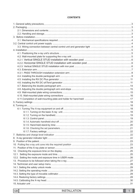
CONTENTS<br />
1. General safety precautions.......................................................................................................................................3<br />
2. Packaging .................................................................................................................................................................3<br />
2.1. Dimensions and contents ................................................................................................................................3<br />
2.2. Handling and storage ......................................................................................................................................3<br />
3. Before installation ....................................................................................................................................................4<br />
3.1. Mechanical specifi cations required .................................................................................................................4<br />
3.2. Central control unit power supply .........................................................................................................................4<br />
3.3. Wiring connection between central control unit and generator light ..............................................................4<br />
4. Installation ................................................................................................................................................................5<br />
4.1. Positioning the x-ray unit’s structure ...............................................................................................................5<br />
4.2. Wall-mounted plate for supporting the x-ray unit ............................................................................................5<br />
4.2.1. Vertical SINGLE STUD installation with wooden post ........................................................................6<br />
4.2.2. Horizontal SINGLE STUD installation with wooden post ....................................................................6<br />
4.2.3. Vertical SINGLE STUD installation with iron post .......................................................................................6<br />
4.3. Extension arm .................................................................................................................................................7<br />
4.3.1. PASS THROUGH installation extension arm ...............................................................................................8<br />
4.4. Installing the double pantograph arm .............................................................................................................9<br />
4.5. Installing the RX <strong>DC</strong> Plus generator ............................................................................................................. 11<br />
4.6. Installing the RX <strong>DC</strong> eXTend generator ........................................................................................................ 11<br />
4.7. Balancing the double pantograph arm ..........................................................................................................14<br />
4.8. Adjusting the double pantograph arm end-stops ..........................................................................................15<br />
4.9. Wall-mounted plate wiring connections .........................................................................................................15<br />
4.10. Wall-mounted plate wiring connections ......................................................................................................16<br />
4.11.Completion of wall-mounting plate and holder for hand-held ......................................................................17<br />
5. Factory settings ......................................................................................................................................................18<br />
6. Turning on...............................................................................................................................................................18<br />
6.1. Turning The X-ray equipment on and off .......................................................................................................18<br />
6.1.1. Turning on the basic X-ray unit ........................................................................................................18<br />
6.1.2. Turning on the handheld ...................................................................................................................19<br />
6.1.3. Control panel ....................................................................................................................................19<br />
6.1.4. Automatic handheld shut off .............................................................................................................20<br />
6.1.5. Hand-held stand-by time ..................................................................................................................20<br />
6.1.6. Checking the set parameters ............................................................................................................21<br />
6.1.7. Factory settings ................................................................................................................................22<br />
7. Batteries and charge level indication ...................................................................................................................22<br />
8. X-ray generator indicator light ...............................................................................................................................22<br />
9. Position of the patient ............................................................................................................................................23<br />
10. Putting the x-ray unit cone into the required position .........................................................................................23<br />
11. Position of the X-ray plate or sensor ....................................................................................................................24<br />
12. Checking the exposure time on the display .........................................................................................................25<br />
12.1. Setting the exposure mode and time ................................................................................................................25<br />
12.2. Setting the mode and exposure time in USER mode .......................................................................................26<br />
13. Procedure to be followed when taking the x-ray..................................................................................................27<br />
14. Technician and user setup menu .........................................................................................................................28<br />
14.1. Setting the safety unlock mode .........................................................................................................................29<br />
14.2. Setting the operating mode ...............................................................................................................................29<br />
14.3. Setting the type of movable collimator...............................................................................................................29<br />
14.4. Restoring factory settings ..................................................................................................................................29<br />
14.5. Calibrating the X-ray head .................................................................................................................................30<br />
15. Actuator unit .........................................................................................................................................................31<br />
GB INSTALLATION<br />
1
16. Control unit card Code 97660515.........................................................................................................................32<br />
17. Basic head control card Code 97660514 .............................................................................................................33<br />
18. Actuator control card Code 97660591 ..................................................................................................................36<br />
19. X-ray head ............................................................................................................................................................37<br />
19.1. Replacing the slip ring assembly .......................................................................................................................39<br />
19.2. Check occupation of radiofrequencies for RX<strong>DC</strong> MyRay PDA..........................................................................41<br />
2 INSTALLATION<br />
GB
1. General safety precautions<br />
Cefl a Sc - Cefl a Dental Group guarantees the safety, reliability and performance of the equipment under the following<br />
conditions:<br />
- Installation and technical service is performed by authorized technicians using Cefl a Sc - Cefl a Dental Group original<br />
spare parts.<br />
- The electrical system in the dental surgery corresponds to standards I.E.C. 60364-7-710;V2 (Standards regarding<br />
electrical systems in a medical environment) or equivalent standards currently in force in the country where the equipment<br />
is installed.<br />
- The place where the x-ray unit is installed must comply with offi cial directives regulating radiation in the country where<br />
the equipment is used.<br />
- The equipment is operated as directed in the instructions manual..<br />
This device complies with part 15 of the FCC Rules. Operation is subject to the following two conditions: (1) This device<br />
may not cause harmful interference, and (2) this device must accept any interference received, including interference<br />
that may cause undesired operation.<br />
This equipment has been tested and found to comply with the limits for a Class B digital device, pursuant to part 15 of<br />
the FCC rules. These limits are designed to provide reasonable protection against harmful interference in a residential<br />
installation. This equipment generates, uses and can radiate radio frequency energy and, if not installed and used in<br />
accordance with the instructions, may cause harmful interference to radio communications<br />
Changes or modifi cations not expressly approved by the party responsible for compliance could void the user’s authority<br />
to operate the equipment.<br />
2. Packaging<br />
2.1. Dimensions and contents<br />
• DIMENSIONS: 103X53X35 CM<br />
• WEIGHT: 35 KG<br />
• CONTENTS:<br />
- Documentation and guarantee<br />
- Disposable jig for installation<br />
- Kit<br />
- Wall back-plate (if requested)<br />
- Wall-mounted plate<br />
- Generator<br />
- Tube<br />
- Extension<br />
- Collimator<br />
- Double pantograph arm<br />
1<br />
2.2. Handling and storage<br />
Indications regarding storage, handling and unpacking are given on the outside of the<br />
cardboard packaging.<br />
These indications must be strictly observed.<br />
1) The package must be kept upright in the direction indicated by the arrows at all times<br />
during handling and storage.<br />
2) Avoid banging the package.<br />
3) Keep the package free from damp.<br />
4) Do not use hooks to handle the package.<br />
5) A nameplate indicates the required ambient conditions for storage.<br />
a) temperature from -15° to 50° C.<br />
b) relative humidity from 10 to 90%<br />
c) atmospheric pressure from 500 to 1060 hPa.<br />
2<br />
3<br />
4<br />
-10 C°<br />
70 C°<br />
RH<br />
10% ÷ 90%<br />
P<br />
500 hPa ÷ 1060 hPa<br />
5<br />
GB INSTALLATION<br />
3
3. Before installation<br />
3.1. Mechanical specifications required<br />
If the wall is thin (hollow bricks or similar), use the backplate (part no. 9660048) to be mounted on the wall or placed on<br />
the side of the wall opposite the wall where the unit is to be installed.<br />
Decide on a suitable system for fi xing the plate according to the characteristics of the wall and its ability to resist a pull<br />
force of 220 Kg applied at each anchorage point.<br />
If the wall is made of cement or solid bricks, use the wall plugs supplied.<br />
Alternatively we recommend using the “FISHER” chemical wall plugs which include:<br />
• Braid type injection insert (item FIP 16X85).<br />
• Threaded bar with bar and washer (item FIP 16M, 8X110).<br />
• Chemical fixer (item FIP C 150).<br />
3.2. Central control unit power supply<br />
The supply line running to the central control unit must be 3x2.5 mm and protected by a bipolar circuit breaker which<br />
conforms to the relevant electrical codes (10 A, 250 V, breaking power at least 6000 A, distance between contacts at<br />
least 3 mm).<br />
The colour of the three conductors (LINE, NEUTRAL and GROUND) must correspond to that established by regulations.<br />
3.3. Wiring connection between central control unit and generator light<br />
This connection enables the generator light (optional) located outside the surgery to be turned on.<br />
To connect the LP generator light to the central control unit, use 2 conductors having a cross-section of 0.5 mm (see<br />
paragraph 4.8.).<br />
LP light supply: 230V - 3x2.5 mm line.<br />
a<br />
f<br />
b<br />
c<br />
e<br />
RX<br />
d<br />
LP<br />
Legenda:<br />
a) SUPPLY LINE<br />
b) CIRCUIT BREAKER 10 A<br />
c) CENTRAL CONTROL UNIT<br />
d) OPTIONAL<br />
e) SUPPLIED<br />
f) NOT SUPPLIED<br />
4<br />
INSTALLATION<br />
GB
4. Installation<br />
The x-ray unit must be installed by a qualifi ed technician in compliance with the installation instructions given below as<br />
regards both the mechanical and electrical parts.<br />
WARNING!<br />
Always check that the voltage indicated on the generator’s nameplate corresponds to that for the electrical<br />
system.<br />
4.1. Positioning the x-ray unit’s structure<br />
Figure POSITIONING<br />
• Block the middle clamp in the opening provided (d) according<br />
to which of the three positions available the structure needs<br />
to be placed in:<br />
A – PRESET CONFIGURATION WITH WALL-MOUNTED<br />
STRUCTURE SET HORIZONTALLY TO THE RIGHT.<br />
B - WALL-MOUNTED STRUCTURE SET VERTICALLY<br />
DOWNWARD.<br />
C - WALL-MOUNTED STRUCTURE SET HORIZONTALLY TO<br />
THE LEFT.<br />
• Secure the pin to the plate using the srews (f) and washers (e)<br />
provided.<br />
d<br />
Figure POSITIONING<br />
A<br />
B<br />
C<br />
4.2. Wall-mounted plate for supporting the x-ray unit<br />
e<br />
f<br />
Figure A<br />
• Determine the position of the x-ray unit by using the INSTALLATION JIG.(code 97042058).<br />
• First check that the plate is at the correct height and perfectly horizontal and then mark out the four points where it is to be<br />
fixed on the wall. Drill the holes and install the most suitable type of fastening system according to the characteristics of the<br />
wall (see paragraph 3.1).<br />
• Pass the supply cable through one of the holes in the wall-mount plate and fix this to the wall by partially tightening the<br />
top and bottom screws.<br />
406.4<br />
Figure A<br />
MAIN<br />
SWITCH<br />
INTERRUTTOR<br />
E<br />
GENERAL<br />
E<br />
14.3<br />
16<br />
POSIZIONE FISSAGGI<br />
A<br />
MURO<br />
SCATOLA ALLACCIAMENTI<br />
A<br />
MURO<br />
71.7<br />
152.5<br />
172<br />
86.5<br />
85.5<br />
11<br />
LOCATION<br />
WALL<br />
FIXING<br />
AXLE ASSE BRACCIO<br />
RADIOGRAFIC<br />
RADIOLOGIC<br />
O<br />
ARM<br />
WALL BOX<br />
CONNECTIONS<br />
14.3<br />
R 10<br />
R 10<br />
60<br />
95<br />
R 10<br />
86<br />
R 10<br />
217.5 217.5<br />
435<br />
GB INSTALLATION<br />
5
4.2.1. Vertical SINGLE STUD installation with wooden post<br />
• Insert the 4 TPSEI M8x35 screws with heads that allow them to be driven with a screw driver provided in the interface plate<br />
• Run the power cord through one of the holes in the interface plate<br />
• Attach the interface plate to the wooden post with no. 3 dia. 3/8'' x L 3'' wood screws (not supplied)<br />
• Attach the x-ray unit’s wall-mounting plate to the interface plate by tightening the washers and nuts provided on the<br />
TPSEI M8x35 screws with heads that allow them to be driven with a screw driver<br />
4.2.2. Horizontal SINGLE STUD installation with wooden post<br />
The interface plate is not needed for 1.5'' wooden posts with 16'' spacing. Simply attach the RX-<strong>DC</strong> plate with no. 4 dia.<br />
3/8'' x L 3'' wood screws (not supplied)<br />
4.2.3. Vertical SINGLE STUD installation with iron post<br />
• Attach the wall-mount counter-plate to the iron posts (not completely seen) with the threaded bars and screws provided<br />
• Attach the interface plate to the counter-plate. Secure the x-ray unit’s wall-mounting plate to the latter<br />
Interface Piastra di<br />
interfaccia plate<br />
RX Piastra<br />
wall-mounting murale RX<br />
plate<br />
Counter-plate<br />
Contropiastr<br />
a<br />
6 INSTALLATION<br />
GB
4.3. Extension arm<br />
WARNING!<br />
Do not lubricate the pin of the extension arm: the wall-mounted plate is provided with self-lubricating bushings.<br />
Figure B<br />
• Insert the pin (b) of the extension arm (c) in the hole provided in the wall-mounted plate.<br />
• Take the clutch (a) from the kit, install it on the plate using the corresponding screws and adjust the arm (c) as required.<br />
Figure B<br />
c<br />
b<br />
a<br />
Figure C<br />
• Use a spirit level to check that the arm (c) is slightly tilted upwards (approx. 1°). If necessary add a shim to the plate<br />
near the bottom wall plugs (d).<br />
• Fully secure the plate.<br />
Figure C<br />
c<br />
d<br />
Figure D<br />
• If the x-ray unit is installed in one of the corners of the dental surgery, make sure the extension arm cannot rotate too<br />
far (90°) by installing the two end-stop pins (included in the kit) on the x-ray unit itself.<br />
• Find the right position for installing the pair of pins (a, b) and insert them in the holes provided using a hammer.<br />
Figure D<br />
b<br />
a<br />
a<br />
b<br />
GB INSTALLATION<br />
7
4.3.1. PASS THROUGH installation extension arm<br />
Install inside cabinet model PXTG92 42.5'' x 49''<br />
Switch at top h=191cm<br />
Check the direction of the pin support: it should be set as shown in fi gure (A) for this type of installation.<br />
Insert the extension arm pin in the hole in the wall-mounting plate from below. Place the washer supplied on top of<br />
the pin and forcefully tighten the ring nut with the pin spanner provided, as shown in the fi gure (B).<br />
Fig. A<br />
Fig. B<br />
Install the clutch (a) as directed in paragraph 4.3 fi gure (B) .<br />
8 INSTALLATION<br />
GB
4.4. Installing the double pantograph arm<br />
WARNING!<br />
The arms are supplied secured together by a belt.<br />
This belt should not be removed until the two free ends of the arms have been connected to their corresponding<br />
attachments: the extension arm (already secured to the wall) and x-ray head.<br />
If the belt is loosened before fixing the arms in place, releasing them abruptly could damage them and the<br />
operator risks being injured.<br />
Figure E<br />
• Take the washer (f) from the kit and position it at point (i) corresponding to the extension arm (c).<br />
• Pass the cable (m) of the pantograph arm (e) through the extension arm (c) so that it comes out of the hole below.<br />
• Install the pantograph arm (e) on the extension arm (c)<br />
NOTE:<br />
The extension arm’s bushing is self-lubricating.<br />
Do not lubricate the pin of the double-pantograph arm.<br />
• Pass the cable (m) through the inside of the extension arm (c) so that it comes out of the wall-mounted plate.<br />
• Install the plugs (g) in the corresponding holes in the extension arm (c).<br />
Figure E<br />
e<br />
f<br />
i<br />
c<br />
g<br />
g<br />
m<br />
GB INSTALLATION<br />
9
Figure F<br />
• Take the grubscrew used to stop rotation (o) from the x-ray unit kit and tighten it at point H (tighten it fully and then<br />
loosen by ½ turn).<br />
NOTE:Turn the pantograph arm to check that the adjustment has been made properly.<br />
• Take the clutch assembly (friction element, screw and 4 curved washers) from the x-ray unit kit and install it at point<br />
L.<br />
NOTE: Insert the curved washers (j) and the friction element (k) as indicated in figure F.<br />
NOTE: The friction element (k) can be placed in the correct position (vertical cut) by inserting a screwdriver<br />
in the hole provided for the screw (n).<br />
Figure F<br />
L<br />
n<br />
j k<br />
o<br />
H<br />
Figure G<br />
• Adjust the clutch which has just been installed.<br />
NOTE:Turn the pantograph arm during the adjustment to check that the clutch is providing the correct<br />
amount of friction.<br />
• Install the plugs (p) on the extension arm (c).<br />
• Attach the adhesive bumper (q) (supplied in the kit) in the centre of the plug at the point indicated in the diagram.<br />
Figure G<br />
q<br />
c<br />
p<br />
Figure H<br />
• There are 2 end-stop screws in the wall-mounted plate to which Loctite has been applied to provide friction. These<br />
have been adjusted according to the length of the extension arm supplied.<br />
NOTE: Work on the screw itself (a) in order to make the extension arm stop before or after.<br />
Figure H<br />
a<br />
10<br />
INSTALLATION<br />
GB
4.5. Installing the RX <strong>DC</strong> Plus generator<br />
Figure I<br />
• Take the generator out of the packaging.<br />
• Insert the pin (a) in the sleeve making sure the respective openings match and secure with the screws (b) provided.<br />
• Insert the power cable in the generator’s pin and run it out of the opening (c) provided.<br />
• Lastly, put on the two side covers montare (d).<br />
Figure I<br />
4.6. Installing the RX <strong>DC</strong> eXTend generator<br />
- Take the generator out of its packaging.<br />
- Lubricate the bush of the pantograph arm and the generator pivot point with grease designed for bearings. (FIAT MR3).<br />
Figure J<br />
GB INSTALLATION<br />
11
- Take the washer (a) from the kit supplied and fi t it in the pin (b) with the protruding tooth (c) pointed towards the righthand<br />
head. (see fi g.K)<br />
Figure K<br />
Position the protruding tooth (c) of the washer (a) in zone 1 of the pin (b). (see fig. L)<br />
WARNING! DO NOT position the protruding tooth (c) of the washer (a) in zone 2 of the pin (b).<br />
Figure L<br />
- Insert the power supply cable of the pantograph arm in the generator pin until it comes out of the hole below (see<br />
point c – fi g. M).<br />
- Raise the cover (a).<br />
- Insert the pin in the sleeve so that it corresponds to the openings provided and then Fit the mounting yoke (d) supplied.<br />
- Lower the cover (a) so that the hole (f) in the cover (a) is aligned with the hole in the internal washer (e).<br />
- Fit the M4x6 self-locking grub screw (g) into the hole (f) and tighten it to 1 mm below the outer surface of the cover<br />
(a).<br />
12 INSTALLATION<br />
GB
Figure M<br />
- Fit the connector of the pantograph arm cable to that of the generator cable.<br />
- Place them inside the hole provided (c).<br />
- Fit the plug (e) supplied into the hole then tighten the screw that is already in place. (see fi g. N)<br />
Figure N<br />
GB INSTALLATION<br />
13
4.7. Installing the collimator<br />
- Take the collimator out of the packaging:<br />
round in case of RX <strong>DC</strong> extend<br />
Figure O<br />
round or rectangular in the case of RX <strong>DC</strong> HyperSphere Plus<br />
Figure P<br />
- Insert it in the generator and block it in place by turning clockwise.<br />
14 INSTALLATION<br />
GB
B<br />
4.8. Balancing the double pantograph arm<br />
Figure Q<br />
If the double pantograph arm does not stay in a stable position, adjust the spring tension by using an 8mm Allen wrench<br />
about 20cm long.<br />
• To adjust the arm (a) connected to the extension: position it as shown in the fi gure and place the wrench at point A.<br />
NOTE:<br />
TIGHTEN (clockwise) if the arm tends to move down.<br />
LOOSEN (anti-clockwise) if the arm tends to move up.<br />
• To adjust the arm (b) connected to the generator: put the 2 covers (c) and (d) on the front pivot point, move the arm<br />
(b) into a horizontal position and insert the key in point B.<br />
NOTE:<br />
TIGHTEN (clockwise) if the arm tends to move down.<br />
LOOSEN (anti-clockwise) if the arm tends to move up.<br />
Figure Q<br />
c<br />
d<br />
B<br />
A<br />
b<br />
a<br />
4.9. Adjusting the double pantograph arm end-stops<br />
Figure R<br />
If the end-stops of the double pantograph arm need to be adjusted, work on the screws (i - l - m - n) shown in the<br />
diagram.<br />
NOTE:<br />
To adjust the screw (n) on the articulated joint of the extension side place the relevant arm (a) in a horizontal position.<br />
Figure R<br />
c<br />
i<br />
b<br />
g<br />
d<br />
e<br />
m<br />
l<br />
h<br />
a<br />
f<br />
n<br />
GB INSTALLATION<br />
15
F2<br />
K1<br />
4.10. Wall-mounted plate wiring connections<br />
Figure S<br />
• Connect the power cable (LINE) to terminal K2, observing the following positions:<br />
L - SUPPLY (BROWN WIRE)<br />
- GROUND (YELLOW/GREEN wire)<br />
N - NEUTRAL (BLUE wire)<br />
• Connect the generator’s power cable to the respective connectors, observing the following positions:<br />
K6 - brown wire and blue wire.<br />
K5 - white wire – black wire – red wire – green wire – purple wire.<br />
Eyelet connectors - Both found near the card (see fi gure).<br />
NOTE: Place the excess cable under the card.<br />
• Connect the 2 control wires (0.5 mm cross-section) for the “generator on” indicator light (LP) to connector K3.<br />
LP<br />
Figure S<br />
230 V<br />
VIOLET<br />
GREY<br />
1<br />
2<br />
N<br />
L<br />
N<br />
L<br />
3<br />
4<br />
K5 K2<br />
VIOLET<br />
GREY<br />
K3<br />
K6<br />
LINE<br />
BROWN<br />
YELLOW/GREEN<br />
BLUE<br />
K2<br />
L<br />
N<br />
K1<br />
1<br />
3<br />
6<br />
2<br />
5<br />
1<br />
4<br />
BROWN<br />
BLUE<br />
2<br />
3<br />
4<br />
16<br />
INSTALLATION<br />
GB
4.11. Completion of wall-mounting plate and holder for hand-held.<br />
Figure T and Figure U<br />
• Pick up the cover (a) and place it over the wall-mounting plate fully tightening the grub screws (b) provided and prescrewed<br />
on the plate.<br />
• Place the cover (c) in the area shown in the fi gure. The door (d) will automatically close when the controller is closed.<br />
• Put the controller label in the required area (e) on the cover directed according to the position in which he wall-mounting<br />
plate is installed.<br />
Figure T<br />
c<br />
a<br />
b<br />
e<br />
d<br />
b<br />
• To install the handheld’s mount (f), refer to the INSTALLATION TEMPLATES.<br />
Figure U<br />
f<br />
GB INSTALLATION<br />
17
5. Factory settings<br />
The x-ray unit is supplied with the following factory settings:<br />
• Anode current: 6/7 mA (NORM mode).<br />
• Sensitivty: level 19.<br />
• Handheld stand by: 5 minutes<br />
• Patient’s built: adult (ADULT symbol selected).<br />
• Collimator presence signaled on the display (collimator symbol off if the rectangular collimator is turned on in the<br />
head).<br />
• Exposure times according to standard R20: 0,010-0,011-0,012-0,014-0,016-0,018-0,020-0,022-0,025-0,028-0,032-<br />
0,036-0,040-0,045-0,050-0,056-0,063-0,071-0,080-0,090-0,100-0,110-0,125-0,140-0,160-0,180-0,200-0,220-0,250-<br />
0,280-0,320-0,360-0,400-0,500-0,560-0,630-0,710-0,800-0,900-1,000.<br />
NOTE:<br />
These times comply with current standards I.E.C. 60601-2-7 (1999) and the ISO 497 series R’20 recommendations<br />
and CANNOT BE MODIFIED.<br />
6. Turning on<br />
6.1. Turning The X-ray equipment on and off<br />
6.1.1. Turning on the basic X-ray unit<br />
The control unit is turned on and off with the main switch (A), as illustrated in the fi gure below. The switch lights up<br />
when the control unit is energized.<br />
NOTE: Whenever turned on, the equipment performs an operational test that takes a few seconds. Once the<br />
test has been completed, a buzzer rings and the indicator light (B) on the X-ray generator lights up at the same time.<br />
NOTE: The exposure time and the parameters displayed when the unit is turned on are the last ones set before<br />
the central control unit was turned off. If the central control unit is left untouched for a few minutes it will go into stand-by<br />
mode. Simply press any key on the control panel to reactivate it.<br />
18 INSTALLATION<br />
GB
6.1.2. Turning on the handheld<br />
The handheld is turned on by pressing any key, except for the one for x-ray emission. A buzzer rings to confi rm the<br />
apparatus has been turned on. The unit will be in the standard confi guration described in detail in paragraph 5 and then<br />
search for the base it works with.<br />
If the base is off, the handheld will not indicate the fi eld nor status “ready”. If the base is latter turned on, the handheld<br />
will detect it within thirty seconds or by pressing any function key on the pushbutton panel.<br />
Handheld identification<br />
number<br />
Pause for<br />
cooling<br />
Possible to save<br />
Field present for<br />
dialoging with “base”<br />
Battery<br />
charge level<br />
Tooth<br />
selection<br />
Body build selection<br />
Exposure time<br />
and dose display<br />
8” round collimator on (12”<br />
rectangular collimator not<br />
attached)<br />
USER mode on<br />
Time/dose unit of<br />
measure<br />
Graduated bar for<br />
thermal load<br />
NOTE: To maximize the scope of the handheld during its use, you should keep it away from walls and metal<br />
tools and above all do not cover the internal aerial at the top of the display in addition also too rapid movement of the<br />
handheld during exposure may reduce the performance. If fl ow could appear on the display error is 31.<br />
6.1.3. Control panel<br />
As illustrated in the fi gure below, the handheld has four function keys and the exposure key.<br />
“Dentition area selection”<br />
key<br />
“Body build selection”<br />
key<br />
X-ray emission light<br />
“Decrease” key<br />
“Increase” key<br />
“X-ray emission” key<br />
GB INSTALLATION<br />
19
The main functions of the keys on the handheld vary according to how they are pressed:<br />
KEY BRIEFLY PRESSED (less than 3 sec.) PRESSED LONGER (more than 3 sec.)<br />
Changes over from ADULT to CHILD Saves, if permitted, the sensitivity of the new tme<br />
and vice versa (takes place when key selected. The memo icon ( ) lights up when the<br />
is released).<br />
data item can be saved.<br />
Changes amongst the various types of<br />
teeth to select the area to be examined.<br />
Increases the exposure times in steps,<br />
according to the set scale.<br />
Increases the exposure times in steps,<br />
according to the set scale.<br />
Displays the exposition time of the tooth in mGy<br />
and, if the key is held down a few more seconds,<br />
in mGy*cm 2 .<br />
Increases the scroll speed of the values in increasing<br />
order.<br />
Increases the scroll speed of the values in decreasing<br />
order.<br />
NO EFFECTS ARE OBTAINED IF THE<br />
KEY IS PRESSED LESS THAN A SE-<br />
COND.<br />
STARTS X-RAY EXPOSURE (the button has to<br />
be held down while the x-rays are being emitted,<br />
“dead man” function).<br />
NOTE: “Dead man” function: the system that starts x-ray exposure with the dedicated key on the wireless<br />
handheld allows x-rays to be emitted only when the user presses and holds down the exposure key. X-ray emission<br />
will stop if the key is released ahead of time.<br />
NOTE: The function related to pressing the key briefl y is performed by pressing the key which will activate the<br />
function assigned to it. On the other hand, to perform the function carried out when the key is held down longer, press<br />
the key until the relative function is started. The buzzer will ring shortly to signal the function has started.<br />
NOTE: Warm-up: When the equipment has not been used for a prolonged period (more than 3 months) or when<br />
turned on for the fi rst time, a number of emissions with short times (0.01-0.02 sec.) are recommended and then<br />
some pictures with 0.1 sec. intervals to better stabilize operation of the x-ray tube before using it.<br />
6.1.4. Automatic handheld shut off<br />
About one minute after the base is turned off the handheld automatically shuts off. Similarly, the handheld will automatically<br />
shut off if it is far away or in any case outside the operating range for interfacing with the base.<br />
6.1.5. Hand-held stand-by time<br />
The entire x-ray unit will switch over to stand-by (even if the base is on) and the handheld will automatically shut off<br />
after approximately fi ve minutes of non-use to save battery power. Press any key, except for the “exposure” key, to turn<br />
the handheld back on showing the last selection made by the user. To change the stand by time, refer to chapter 14<br />
regarding the handheld’s “Technician and user setup menu”.<br />
20 INSTALLATION<br />
GB
6.1.6. Checking the set parameters<br />
WARNING! Before actually taking an exposure, make sure the exposure parameters for the examination<br />
in progress are correctly set.<br />
- Checking the collimator used.<br />
The icon<br />
on the handheld’s screen should be on or off, depending on the operating mode selected:<br />
- Icon ON: indicates that the cylindrical collimator (8") is activated.<br />
- Icon OFF: indicates the rectangular collimator (12") is activated.<br />
NOTE: After turning the collimator on or off, the preset exposure times and icon will automatically be modifi ed<br />
within a few seconds.<br />
- Checking the selected body build.<br />
- “Child” selected: indicates the x-ray unit is set for patients with small builds.<br />
- “Adult” selected: Indicates the x-ray unit is set for patients with average-large builds.<br />
Average/large build<br />
(ADULT) selected<br />
Small build (CHILD)<br />
selected<br />
To change the selection, press the relative button.<br />
NOTE: After the change has been made, the preset exposure times will automatically be modified.<br />
- Checking the set intraoral examination<br />
Upper molars<br />
Lower incisors<br />
Upper canines/bicuspids or rear<br />
”bitewing”<br />
Lower canines/bicuspids<br />
Upper incisors or front ”bitewing”<br />
Lower molars<br />
GB INSTALLATION<br />
21
6.1.7. Factory settings<br />
The MyRay RX <strong>DC</strong> x-ray unit is supplied with the following factory settings:<br />
• Operating mode: AUTO.<br />
• Sensitivty: level 19.<br />
• Handheld stand by: 5 minutes<br />
• Exposure times as per standard R20: 0,010 - 0,011 - 0,012 - 0,014 - 0,016 - 0,018 - 0,020 - 0,022 - 0,025 - 0,028<br />
- 0,032 - 0,036 - 0,040 - 0,045 - 0,050 - 0,056 - 0,063 - 0,071 - 0,080 - 0,090 - 0,100 - 0,110 - 0,125 - 0,140 - 0,160 -<br />
0,180 - 0,200 - 0,220 - 0,250 - 0,280 - 0,320 - 0,360 - 0,400 - 0,500 - 0,560 - 0,630 - 0,710 - 0,800 - 0,900 - 1,000.<br />
NOTE: These times comply with current standards I.E.C. 60601-2-7 (1999) and the ISO 497 series R’20<br />
recommendations and CANNOT BE MODIFIED.<br />
7. Batteries and charge level indication<br />
The handheld runs on two widely available AA alkaline batteries to assure siffi cient stand-alone operation.<br />
The charge level of the batteries is given on the screen as follows:<br />
Battery fully charged (a symbol does not appear in the area that shows the battery charge level).<br />
Battery half-charged.<br />
Battery charge level low or almost dead (causing the handheld to automatically shut off).<br />
NOTE: The batteries should be removed from the handheld if it is not going to be used for an extended<br />
period.<br />
8. X-ray generator indicator light<br />
In RX <strong>DC</strong> Plus versions, the x-ray generator comes with an indicator light (B) that signals apparatus status:<br />
• myray color (purple) > x-ray unit on (regular condition)<br />
• Flashing myray color (purple) > stand-by (low consumption)<br />
• Blue<br />
> x-ray one – head released<br />
• Yellow<br />
> x-rays being emitted<br />
• Red<br />
> fault<br />
In the RX <strong>DC</strong> eXTend version, the indicator light is not available.<br />
22 INSTALLATION<br />
GB
9. Position of the patient<br />
A positioner or alignment device specifi c for the selected image receiver should always be used to assure the x-rays<br />
are correctly aligned regardless of the position the patient’s head is in.<br />
10. Putting the x-ray unit cone into the required position<br />
Position the x-ray head so that the cone is aligned with the image receiver.<br />
RX <strong>DC</strong> Plus versions feature Hypersphere technology that allows the x-ray head to turn endlessly on both the horizontal<br />
and vertical planes.<br />
The x-ray head is initially blocked by an electromechanical brake.<br />
The head can be tilted into the position required to take the x-ray by touching the unlock areas.<br />
To lock it again, release the unlock areas.<br />
Unlock button<br />
Unlock button<br />
NOTE: Firmly hold the head with both hands when putting it in place.<br />
It is possible to set a safety unlocking mode that allows the head to be turned only by pressing both unlock buttons. This<br />
prevents the head from unlocking unexpectedly after one of the two unlock buttons has been accidentally pressed. To<br />
activate this mode, refer to “Advanced options” in chapter 14.1.<br />
GB INSTALLATION<br />
23
11. Position of the X-ray plate or sensor<br />
The parallel technique, where applicable, provides more accurate images in terms of size compared to the bisecting technique.<br />
A rectangular collimator, with 30 cm focus-skin distance, is always preferable to obtain better quality pictures.<br />
To avoid exposing the image receiver only partly (whether it is a sensor or photostimulable phosphorus plate system)<br />
an alignment device that gives rectangular collimators guidelines should be used. These lines are usually given on the<br />
alignment ring.<br />
Parallel technique<br />
INCISORS<br />
CANINES<br />
PREMOLARS<br />
MOLARS<br />
UPPER<br />
LOWER<br />
INCISORS<br />
CANINES<br />
PREMOLARS<br />
MOLARS<br />
• The x ray emission axis is perpendicular to the image receiver (for example a sensor or photostimulated<br />
phosphor plate) which in turn is parallel with the tooth’s long axis.<br />
• As a result, the picture of the tooth will only be deformed by the divergence of the x rays in relation to the<br />
focus spot.<br />
• Radiographic enlargement may reach up to 15%.<br />
• For some “special” pictures, for example occluded ones, it may be necessary to remove the rectangular collimator<br />
and use the round one if a positioner is not present.<br />
24 INSTALLATION<br />
GB
12. Checking the exposure time on the display<br />
Before starting exposure, check the time setting on the handheld’s screen (see the tables with the original exposure<br />
times, paragraph 3.1.4). To change the value, use keys “+” and “-”.<br />
NOTE:<br />
Changing the exposure time is only temporary: if the new time is not stored in the memory it will be lost.<br />
12.1. Setting the exposure mode and time<br />
The exposure parameters are set by following the directions given below:<br />
1) select the tooth to be examined<br />
2) select the patient size<br />
The exposure time is automatically shown on the handheld screen.<br />
NOTE: each tooth and patient size selected is displayed for approximately 1 second according to the<br />
operating mode (En60, En63 or En65) used.<br />
The suggested exposure time can be changed with keys and . Exposure times ranging from 0.01s and<br />
1.00s belonging to the R’20 scale can be set. Random exposure times different from the ones provided in the R’20<br />
scale cannot be set.<br />
When the exposure time displayed differs from the default setting, icon comes on.<br />
To save the new setting, make sure icon is on and then press and hold down key for approximately 2 seconds.<br />
The handheld will beep to confi rm the setting has been saved. At this point, make sure icon is off.<br />
NOTE: if the exposure time is not saved, the change made will be lost after a new entry or as soon as the<br />
handheld changes over to stand-by.<br />
Important: after customized settings have been made, the “Original exposure values charts” are no<br />
longer valid.<br />
If icon is displayed while the exposure time is changed, it means the set time cannot be saved for the selected<br />
tooth-patient size combination. In any case, the x-rays can be taken with the set time.<br />
Important: when the suggested exposure time is changed, the sensitivity factor is also modified (by<br />
default set to F=19). Once this change has been saved, it is applied to all the teeth and both patient<br />
sizes<br />
The exposure time can also be modifi ed by changing the sensitivity factor.<br />
GB INSTALLATION<br />
25
Press keys and at the same time , the actual sensitivity factor will be displayed.<br />
Use keys and to change the value from 3 to 25. If the displayed value differs from the one previously<br />
saved, icon comes on. To quit this mode, press key or . The change made to the sensitivity factor is<br />
applied to all the teeth and both patient sizes.<br />
The selected operating mode is always used for each tooth and patient size combination in modes En60, En63 and<br />
En65.<br />
In AUTO mode, each tooth and patient size combination is associated to the best mode from amongst the ones available.<br />
In this mode it is not possible to assign a mode other than the default one to each combination. To set the mode,<br />
refer to paragraph 12.2 “Setting the mode and exposure time in USER mode”.<br />
To change the mode amongst En60, En63, En65 and AUTO refer to paragraph 14.2 “Setting the operating mode”.<br />
12.2. Setting the mode and exposure time in USER mode<br />
In USER mode, it is possible to assign an exposure time and a mode from amongst En60, En63 and En65 to each<br />
tooth-patient size combination.<br />
The default setting corresponds to the AUTOmode settings with sensitivity factor F=19<br />
To activate USER mode regardless of the mode currently being used, press keys and at the same time.<br />
Icon<br />
will come on to signal USER mode is active.<br />
To deactivate USER mode press keys and again (icon goes off).<br />
The exposure parameters are set as directed below:<br />
1) select the tooth under examination<br />
2) select the patient size.<br />
The exposure time is automatically displayed on the handheld.<br />
NOTE: It is not possible to access the sensitivity factor menu in USER mode. In addition, keys<br />
and<br />
are inoperative in User mode.<br />
The exposure times and mode assigned to the tooth – patient size combinations are custom set by following the directions<br />
given below:<br />
1) press and hold down key about two seconds. Customized settings can be entered and icon comes on.<br />
2) select the desired tooth-patient size combination<br />
3) change the exposure time with keys and .<br />
NOTE: it is possible to set exposure times ranging from 0.01s and 1.00s that are part of the R’20 scale.<br />
4) press keys and simultaneously to open the menu used to select the operating mode<br />
5) select the operating mode with keys and<br />
6) quit the menu and press key to make the entry operative (if key is pressed, the menu will be quit without<br />
changing the previous setting).<br />
7) press and hold down key for approximately two seconds to confi rm the entry and disable customized settings<br />
(icon goes out).<br />
NOTE: it is possible to set the exposure parameters for several combinations. To do this, repeat steps<br />
2 to 6 before going on to step 7.<br />
26 INSTALLATION<br />
GB
13 Procedure to be followed when taking the x-ray<br />
• Pick up the handheld and go a safe distance away (at least 2 meters) maintaining visual contact with the patient and<br />
x-ray unit during the exposure. Make sure “READY” is indicated.<br />
• Tell the patient to stay still.<br />
• Press and hold down the “Exposure” key on the handheld until the audible warning sound (beep) stops and the<br />
yellow light goes out.<br />
“X-ray emission” key<br />
Light on control panel illuminated during x-ray emission<br />
NOTE: If the “EMIT X-RAY” key is released at any time, exposure will be interrupted and error code E01<br />
will appear on the display.<br />
• Once exposure has been completed, it is possible to proceed with the next exposure unless the x-ray unit has<br />
reached the maximum allowable temperature. The percentage the cone exceeds the maximum allowable temperature<br />
is always shown on the screen (see icon below).<br />
• Once the temperature has been reached, wait the pause time for cooling signaled by symbol .<br />
• At this point the exposure function will be disabled until the screen shows “READY” again.<br />
• As soon as “READY” appears on the handheld, another exposure can be taken.<br />
GB INSTALLATION<br />
27
14. Technician and user setup menu<br />
The handheld allows a number of work parameters to be viewed and edited by simply pressing a combination of keys present on the control panel.<br />
Key serves to confirm/save the function, key is used to undo/quit the menu while keys and edit<br />
the values of the selected parameters on all the setup menus.<br />
Proceed as directed below to access the menus:<br />
Combination of keys<br />
+<br />
+<br />
+<br />
+<br />
Description<br />
Sensitivity levels<br />
Press these two keys to adjust the sensitivity levels (determined based on the table given below and type of<br />
sensor/receptor used). Set the current sensitivity level to a value within the allowable range (on a scale from 1<br />
to 25), with keys “+” and “-”; to confi rm the desired level and go back to the main screen press key “adult”.<br />
Setting the rated current (7mA or 3.5mA)<br />
Press these two keys at the same time to set the rated current used to take the x-rays.<br />
Two values can be set: 7mA indicated by “NORM”<br />
and 3.5mA indicated by “SENS”. We highly recommend always using “NORM” unless otherwise indicated by<br />
technical service personnel.<br />
The present configuration of the x-ray unit will be displayed when the hand held is turned on.<br />
Hold down these two keys to go to the set up menu (from P 01 to P 07).<br />
Press key “Build” to make the selection. Once within the individual confi gurations, they can be scrolled with keys<br />
“+” and “-” and selected by pressing key “Build” again. Key "tooth" quits set up without saving the setting.<br />
The confi gurations are given in detail below:<br />
P 01: Sets the stand by time (from a minimum of 5 to a maximum of 30 minutes).<br />
P 02: Assigns an identification tag to the x-ray unit’s base (from 1 to 5 or none).<br />
P 03: Shows the list of software versions-<br />
P 04: Handheld code display<br />
P 05: Activates/deactivates the safety unlock mode (see section 14.1) (only RX <strong>DC</strong> Plus).<br />
P 05: Reserved. (only RX <strong>DC</strong> eXTend)<br />
P 06: Selects the operating mode (En60, En63, En65 and AUTO).<br />
P 07: Sets the type of removable cone used<br />
Technician setup menu<br />
Hold down these two keys when in position P07 on the user menu, to go to the advanced setup menu (from<br />
P 10 to P 18).<br />
As for the previous menu, the selection is made by pressing key “adult”. Once the single confi gurations have<br />
been accessed, scroll them with keys “+” and “-” and make the selection by pressing key “adult” again. The<br />
items that can be set are given below:<br />
P 10: Supply voltage setting<br />
a: A shot can be taken to improve the reading<br />
b: The mains voltage is shown in real time on the screen and refreshed every 5 seconds. If a shot is taken the<br />
reading is refreshed every second during the cool down period.<br />
c: As soon as key + or – is pressed the display is blocked until the change is confi rmed.<br />
P 11: Displays the voltage or charge level of the batteries; the reading may range from 1.5 to 3Vdc.<br />
P 12: StepUp value, this value should be 3.3 + o – 0.2Vdc if a value outside this range is displayed there is a<br />
fault in the handheld card.<br />
P 13: shows the type of batteries used for the handheld:<br />
a: “ALCA” default setting, indicates that disposable alkaline batteries are being used.<br />
b: “NIHM” indicates rechargeable batteries are being used **<br />
P 14: indicates DEMO status of the handheld<br />
a: “PALM” default setting, standard operating mode<br />
b: “DEMO” when the handheld is in this mode it does not communicate with the head but READY is shown on<br />
the display even if the control unit is shut off.<br />
P 15: indicates DEMO status of the entire system<br />
a: “SHOT” default setting, standard operating mode<br />
b: “DEMO” a pad lock shaped icon appears on the display; all the functions are operative as if in standard<br />
mode, the handheld communicates regularly with the head but x rays are not emitted when the shoot button<br />
is pressed.<br />
P 16: STAND BY function of the head is shut off<br />
P 17: When this menu is opened, the handheld starts a special procedure to deactivate the DSP default settings.<br />
A number of shots are required at a set time of 0.01 sec to recalibrate the card. Once the menu has been<br />
opened, 20 will appear on the display. Press key “Patient” again to completely cancel the previous setting.<br />
(See par. 14.5.)<br />
P 18: This menu starts the procedure so that the handheld can work with the head.<br />
28 INSTALLATION<br />
GB
Activating/deactivating the USER mode Icon comes on to signal USER mode is activated.<br />
+<br />
14.1. Setting the safety unlock mode<br />
The MyRay RX <strong>DC</strong> x-ray unit has a safety unlock for the ball joint.<br />
The default setting allows the ball joint to be disengaged by simply touching one of the keys present on the front of the<br />
head. To prevent accidental contact with the keys from unexpectedly disengaging the ball joint (and therefore causing<br />
undesired movement of the head), the safety unlock mode can be activated. In this mode, the ball joint is disengaged<br />
only if both keys are activated at the same time.<br />
To set the safety unlock mode, press keys and to go to the set up menu. Scroll the parameters up to<br />
parameter P05 and press key . Scroll the options to select “ON” and press key . Press key to quit<br />
the set up menu.<br />
14.2. Setting the operating mode<br />
The MyRay RX <strong>DC</strong> x-ray unit features the following operating modes:<br />
• En60: all the x-rays are taken at 60KV and 7mA.<br />
• En63: all the x-rays are taken at 63KV and 6mA.<br />
• En65: all the x-rays are taken at 65KV and 6mA.<br />
• AUTO: the system automatically selects the best setting from amongst En60, En63 and En65 for each tooth-patient<br />
size combination.<br />
NOTE: the current setting is displayed on the handheld for approximately 1 second for each toothpatient<br />
size selected before the relative exposure time is shown.<br />
To set the operating mode, press keys and to go to the set up menu. Scroll the parameters up to parameter<br />
P06 and then press key . Scroll the options to fi nd the desired operating mode and then press key . Press<br />
key to quit the set up menu.<br />
14.3. Setting the type of movable collimator<br />
The MyRay RX <strong>DC</strong> x-ray unit has the following removable cones:<br />
• Rectangular 35x45 mm (only RX <strong>DC</strong> Plus)<br />
• Round Ø55 mm<br />
• Rectangular 31x41 mm (to be attached to the Ø55 mm round cone)<br />
• Rectangular 22x35 mm (to be attached to the Ø55 mm round cone)<br />
•<br />
NOTE: in order to obtain top performance of the x-ray unit, set the cone according to the type used.<br />
To set the type of cone, press keys and to go to the set up menu. Scroll the parameters up to parameter<br />
P07 and then press key . Scroll the options to fi nd the type of cone used and press key . Press key<br />
to quit the set up menu.<br />
14.4. Restoring factory settings<br />
To restore the factory settings (see paragraph 6.1.7.) press keys and to go to the set up menu. Press keys<br />
GB INSTALLATION<br />
29
and<br />
simultaneously. "rESS" will briefl y appear and the handheld will be rebooted.<br />
14.5. Calibrating the X-ray head<br />
This operation requires the execution of 20 shots, at a pre-set time of 0.01 s, during which X-ray<br />
emission occurs. It is therefore necessary to pay close attention.<br />
Turn on your handheld and menu position P17. To access this menu press the keys +, ,scroll the<br />
menu using the button until you see P07, press + to enter the menu technical and<br />
press the key repeatedly until P17, press 2 times the button to enter the menu and confi rm the calibration.<br />
Number 20 appears on the handheld. Make the 20 shots until the counter reaches 0. Wait about<br />
15s and press the button to exit the menu. If the words should appear on the remote E03, wait 10 seconds<br />
and press the button again careful not to advance the issue ever since the firing button, in case<br />
of error, you must repeat the procedure from the beginning.<br />
30 INSTALLATION<br />
GB
16. Control unit card Code 97660515<br />
RT--<br />
AUX<br />
RT+<br />
GND<br />
P1<br />
P2<br />
LAMP<br />
LAMP<br />
1 2 3 4 5 6<br />
K5<br />
1 2 3<br />
K6<br />
1 2<br />
K3<br />
F2<br />
F1<br />
L_2<br />
L_1<br />
N_1<br />
N_2<br />
1<br />
2<br />
3<br />
4<br />
K1<br />
SCHEDA CENTRALINA RX <strong>DC</strong><br />
97660515<br />
DL1=V_LINE<br />
DL2=V_BUS<br />
DL3=BUS OK<br />
DL4=V_DRVR<br />
1<br />
2<br />
J1<br />
DL5=READY<br />
DL6=ENABLE<br />
DL7=V_CTRL<br />
DL8=HV_ON<br />
L<br />
N<br />
1<br />
2<br />
3<br />
K2<br />
Diagnostic Led indicators<br />
LED Color Status<br />
DL1<br />
V_LINE<br />
DL2<br />
V_BUS<br />
DL3<br />
BUS_OK<br />
DL4<br />
V_DRVR<br />
DL5<br />
READY<br />
DL6<br />
ENABLE<br />
DL7<br />
V_CTRL<br />
DL8<br />
HV_ON<br />
Fuses<br />
Red On Indicates 230Volt input voltage if 110Volt the led indicator is illuminated but not as<br />
bright.<br />
Red On Indicates the input voltage to the capacitors.<br />
Green On Indicates the supply voltage is correct<br />
Green On Indicates the power control part fed 12Volt<br />
Yellow On If the head is connected it indicates READY status, relay RL1 is closed, the indicator<br />
light’s signal is activated<br />
Yellow Off It lights up if x-rays are emitted.<br />
Green On Indicates 15Volt output voltage to supply the card inside the head<br />
Not used<br />
F1 6,3A Main fuse if blown all the led indicators are off.<br />
F2 1,6A Fuse for capacitors if blown only DL1 is illuminated all the others are off.<br />
Deep-switch<br />
Con corrente di utilizzo 230Volt Tutti i deep-switch devono essere in posizione OFF, mentre se si utilizza una corrente di<br />
110Volt il deep-switch 1 (se la versione di software della scheda è la 1.2) deve esse posizionato in ON. Se la versione<br />
del software è la 1.1 deve essere posizionato in ON solo il deep-switch 4.<br />
32<br />
INSTALLATION<br />
GB
17. Basic head control card Code 97660514<br />
RT--<br />
AUX<br />
RT+<br />
GND<br />
V+15<br />
EARTH<br />
1 2 3 4 5 6<br />
K2<br />
KF2<br />
KF1<br />
1<br />
2<br />
K1 3<br />
4<br />
FL_OUT<br />
GND_FIL<br />
VFB<br />
FB<br />
SCHEDA TESTATA RX <strong>DC</strong><br />
97660514<br />
1<br />
2<br />
3<br />
K4 4<br />
5<br />
6<br />
7<br />
V+15<br />
GND<br />
CAP_SDA<br />
CAP_CLK<br />
CONE_SW<br />
HAND_SW1<br />
HAND_SW2<br />
DL1=DSP<br />
DL2=VDD<br />
DL3=CPU<br />
DL4=ERR<br />
DL5=NTWK<br />
DL6=CONE<br />
DL7=HNDL<br />
DL8=PWM<br />
DL9=ACT<br />
DL10=FIL<br />
K3<br />
1<br />
2<br />
3<br />
4<br />
5<br />
GND<br />
V+15<br />
EN_ACT<br />
EN_S/U<br />
HV_FB<br />
K5<br />
1 2<br />
Gruppo CPU led LED unit CPU<br />
Faults are signaled by two groups of<br />
leds:<br />
- CPU led unit<br />
- DSP led indicator<br />
DSP Gruppo led LED indicator CPU<br />
DL1=DSP<br />
GB INSTALLATION<br />
33
Diagnostic Led indicators<br />
LED Color Status<br />
DL1<br />
DSP<br />
DSP LED INDICATOR<br />
Yellow Flashing If the diagnostic Led indicator fl ashes:<br />
once a second everything is OK<br />
once every 0.5 a second count the times it fl ashes and check the error in the<br />
error table<br />
very quickly check the error on the handheld<br />
When turned on, the DSP executes internal diagnostics and then displays the<br />
FW version using two fl ashing sequences separated by pauses: the first sequence<br />
indicates version code xx while the second revision code yy. The led<br />
fl ashes regularly immediately after showing the version.<br />
The version was not displayed in FW versions 1.2 or earlier.<br />
CPU LED UNIT<br />
LED Color Status<br />
DL2<br />
VDD<br />
Green On Indicates 3.3Volt input voltage<br />
DL3<br />
CPU<br />
Yellow Flashing If the diagnostic Led indicator fl ashes::<br />
once a second everything is OK<br />
If steady replace the card<br />
DL4<br />
ERR<br />
DL5<br />
NTWK<br />
DL6<br />
CONE<br />
DL7<br />
HNDL<br />
DL8<br />
PWM<br />
DL9<br />
ACT<br />
DL10<br />
FIL<br />
Red Off Lights up to signal an error<br />
Green On Indicates the radio frequency communication network has been created<br />
Not used<br />
Yellow Off Lights up if one of the two keys is pressed<br />
Yellow On Indicates the indicator light is illuminated<br />
It works simultaneously with DL5 for card 97660515<br />
Yellow Off If illuminated it indicates the actuator’s button has been pressed and the output<br />
signal from this card has been generated<br />
Yellow Off If illuminated it indicates voltage at the fi lament, on during preheating<br />
When turned on, the CPU executes internal diagnostics and then displays the FW version using two fl ashing sequences<br />
separated by pauses: the fi rst sequence indicates version code xx while the second revision code yy. The led fl ashes<br />
regularly immediately after showing the version. Red led ERR goes out when the version is about to be displayed.<br />
If the network forming procedure is not successfully completed, led DL5 – NTWK stays off.<br />
In the event of an DSP error led DSP will flash quickly:<br />
• DL1=DSP: Once every 0.5 sec.: count the number of times it flashes between pauses and read the error code<br />
in the error table.<br />
• DL1=DSP: Very fast: check the error code given on the handheld.<br />
If the DSP is faulty, the DSP error subcode can be viewed on the handheld by pressing keys “tooth” and “+” at the<br />
same time, it assumes format xxxx (e.g. 8033).<br />
34 INSTALLATION<br />
GB
The DSP can also signal an alarm condition. This condition is signaled when led DL1=DSP fl ashes faster than usual<br />
separated by pauses. The number of times it fl ashes between pauses indicates the alarm code.<br />
In the event of a CPU fault, the status of the CPU leds is as follows:<br />
• DL3=CPU flashing yellow<br />
• DL4=ERR illuminated red<br />
Both conditions may be present at the same time. This indicates that two errors have been identifi ed (from both the<br />
DSP and CPU) or the DSP caused a fault which, in turn, caused the CPU error. In this case, the error code is shown<br />
on the handheld in format Exx.<br />
Replacing the basic head control card<br />
Pull out the collimator and panel stop ring, take off the screw cover caps and loosen the screws that secure the lower<br />
cover. Detach all the connectors and work on the two support pins to pull out the card. Put the new card back in the<br />
correct position, being careful to run the cables behind the card support pins as shown in the fi gure. Make sure they do<br />
not pass in front of the x-ray collimator.<br />
Before closing the cover, turn on the x-ray unit and make sure the diagnostic led indicator is as shown in the table.<br />
When the head’s basic control card is replaced, the hand held has to be associated to the head by following the instructions<br />
given in the relative paragraph.<br />
IMPORTANT: The head has to be calibrated with function P17 on the technical menu when this card is replaced. .<br />
Throughout this operation, 20 pictures are taken during which x-rays are emitted, therefore be extremely careful.<br />
GB INSTALLATION<br />
35
19. X-ray head<br />
Replacement<br />
Follow the instructions given above to remove the basic head control card Code 97660514. Detach all the cables connected<br />
to the head that may get in the way. Loosen the screw A that secures the head, move it to the rear and lift it as<br />
shown in the fi gure.<br />
IMPORTANT: The head has to be calibrated with function P17 on the technical menu when replaced. .<br />
Throughout this operation, 20 pictures are taken during which x-rays are emitted, therefore be extremely careful. (See<br />
par. 14.5.)<br />
A<br />
To reinstall the head, perform the procedure in reverse order, being careful to lay the cables properly.<br />
GB INSTALLATION<br />
37
Radiogenic palmtop computer-head association<br />
If the control palmtop computer or the head control Code 97660514 needs to be replaced it is only necessary to associate<br />
the palmtop with the head. To do this, you fi rst need to set the head in combination mode (an operation that can<br />
be done in two different ways) then send a recognition signal from the head's remote control.<br />
1) Setting the head in combination mode.<br />
This procedure can only be activated within ten seconds of the radiographic unit being turned on.<br />
a) Remove the collimator from the head, turn on the radiographic unit. You will hear a beep, wait for a few seconds<br />
until the light on the head turns violet, then turn the collimator microswitch on and off at least seven times. The<br />
head will emit a beep that confi rms the head has switched to combination mode and the led on the head will go<br />
red.<br />
b) Remove the collimator from the head, turn on the radiographic unit, you will hear a beep, wait for a few seconds<br />
untill the light on the head goes violet, press and release the right-hand head release button, press and release<br />
the collimator microswitch, press and release the left-hand head release button. You will hear a beep that confi rms<br />
the head has switched to combination mode and the led on the head will go red.<br />
If the procedure is unsuccessful, turn off the head, wait a few seconds and start again.<br />
2) Send the recognition signal from the palmtop computer to the head:<br />
Turn on the handheld and go to menu P18. This menu is accessed by pressing keys + . Scroll<br />
the menu with key until P07 appears. Press + to access the technical menu and<br />
press key several times until P18 is displayed. Press key to open the menu and confi rm association.E14<br />
will appear on the remote control. Press key<br />
to reset: If association has been successfully<br />
completed the radio fi eld icon<br />
not the case, repeat the operation.<br />
should appear on the control hand held with the word READY. If this is<br />
Turn on the hand held and go to menu P18. Press keys + to access this menu. Scroll the<br />
menu with key until P04 appears. Press + to go to the technical menu and press key<br />
several times until P18 is displayed. Press key<br />
to open the menu and confi rm association. If<br />
association has been successfully completed the radio fi eld icon<br />
case, repeat the operation.<br />
with the word READY. If this is not the<br />
IMPORTANT: If the X-ray unit-Handheld are associated using this mode, the x-ray unit has to be calibrated with<br />
function P17 on the technician’s menu.<br />
Exercise extreme caution during this operation as 20 pictures are taken at a preset time of 0.01s, throughout<br />
which x-rays are emitted(see par. 14.5).<br />
38 INSTALLATION<br />
GB
19.2. Check occupation of radiofrequencies for RX<strong>DC</strong> MyRay PDA<br />
The procedure described below enables the user to check the availability of radio frequencies on the channels of communication<br />
used by the RX<strong>DC</strong> MyRay remote control PDA.<br />
Open the battery compartment of the PDA and remove the batteries.<br />
fi g.1<br />
Using a fi ne-tipped screwdriver, move selector 2 of the dip-switch shown in fi gure 2 in the direction indicated by the<br />
arrow.<br />
fi g.2<br />
The PDA enters radiofrequency disturbance detection mode. When switched on, the display shows the channel to be<br />
examined (C11). Pressing “+” and “-” chooses the channel (C11-C26). Pressing the “patient” key displays a percentage<br />
value representing the signal quality on the selected channel. See fi g. 3<br />
GB INSTALLATION<br />
41
fi g.3<br />
If, on most channels, the values are higher than 80%, PDA features are guaranteed. During normal use, the PDA performs<br />
automatic scans of the channels available and uses the frequencies available for communication.<br />
Once the test on the radiofrequencies has been completed, remove the batteries again, moving selector 2 of the dipswitch<br />
shown in fi g. 2 back to the starting position.<br />
42 INSTALLATION<br />
GB
Error codes given on the handheld<br />
When an error appears on the handheld screen it can be reset by pressing keys or to set the x-ray<br />
unit back to READY. If the error is still displayed even after pressing the two keys mentioned above, refer to the error<br />
code and solution given in the table below.<br />
Handheld errors<br />
N° Error code description Solution<br />
E 01 Button released in advance Hold down the button to take the x-ray again until the beep<br />
stops.<br />
E 02 Max. shooting time 7s Take the x-ray again. If the problem persists, go near the<br />
head and try again.<br />
E 03 CPU internal error Take out the batteries to reset the handheld. Wait a few<br />
seconds, put the batteries back in and take the x-ray. If the<br />
problem persists, replace the handheld.<br />
E 04 Software internal error Take out the batteries to reset the handheld. Wait a few<br />
seconds, put the batteries back in and take the x-ray. If the<br />
problem persists, replace the handheld.<br />
E 05 ALU internal error Take out the batteries to reset the handheld. Wait a few<br />
seconds, put the batteries back in and take the x-ray. If the<br />
problem persists, replace the handheld.<br />
E 06 Status switching too long Take the x-ray again. If the problem persists, go near the<br />
head and try again.<br />
E 07 RF fi eld too low ( 16 consecutive messages lost) Take the x-ray again. If the problem persists, go near the<br />
head and try again.<br />
E 08 Incorrect fi rmware version Update the fi rmware for the handheld and head control<br />
card.<br />
E 09 Wrong handheld serial number Enter the correct handheld serial number.<br />
Head control card errors Code 97660514<br />
N° Error code description Solution<br />
E 10 Button released in advance Hold down the button to take the x-ray again until the beep<br />
stops.<br />
E 11 Cone type error Wait approximately 4/5 before taking another x-ray after removing<br />
or putting on the collimator cone.. Hold down the<br />
button to take the x-ray again until the beep stops.<br />
E 12 Hardware internal error Reset the x-ray unit by shutting it off with the main switch.<br />
Wait a few seconds, turn the x-ray unit back on and take the<br />
x-ray again. If the problem persists, replace the basic head<br />
control card Code 97660514<br />
E 13 Emission time greater than 4.9s Reset the x-ray unit by shutting it off with the main switch.<br />
Wait a few seconds, turn the x-ray unit back on and take the<br />
x-ray again. If the problem persists, replace the basic head<br />
control card Cod. 97660514<br />
E 14 Internal cycle error Reset the x-ray unit by shutting it off with the main switch.<br />
Wait a few seconds, turn the x-ray unit back on and take the<br />
x-ray again. If the problem persists, replace the basic head<br />
control card Code 97660514<br />
GB INSTALLATION<br />
43
E 15<br />
E 16<br />
DSP error<br />
DSP error detected. Check the error subcode by press keys<br />
“tooth” and “+” at the same time.<br />
0001 Overvoltage HW.<br />
0002 Overcurrent HW.<br />
0004 Overvoltage SW. It may be caused by incorrect calibration<br />
or after an extended period of inactivity, Perform<br />
the calibration procedure from menu P17.(par.14.5.)<br />
0008 Overcurrent SW. It may be caused by incorrect calibration<br />
or after an extended period of inactivity, Perform<br />
the calibration procedure from menu P17.(par.14.5)<br />
0040 Anode voltage not zero. Replace the basic head control<br />
card code 97660514.<br />
0080 Anode voltage not zero. If the problem persists, replace<br />
the basic head control card code 97660514.<br />
0100 Filament voltage not zero. If the problem persists, replace<br />
the basic head control card code 97660514.<br />
0200 Tube fi lament faulty or cable (code 97520672) between<br />
monoblock card (code 97660511) and head card (code<br />
97660514) not connected or interrupted.<br />
1000 Parameter incorrect. If the problem persists, try resetting<br />
the calibration values from menu P17 and then calibrate<br />
again. (par.14.5.)<br />
E 17 Actuator overload Indicates the actuator that disengages the ball joint has been<br />
used for a prolonged period. Wait for the device to cool down<br />
(about 15 minutes) to reset the system. This error is given only<br />
in version 2.0.<br />
E 18 Mains voltage over maximum limit (more than 15%) Make sure the supply voltage corresponds to the rated one<br />
(menu P10)<br />
E 19 Mains voltage below minimum limit (more than 15%) Make sure the supply voltage corresponds to the rated one<br />
(menu P10)<br />
E99 General error Shut off the x-ray unit with the switch to reset it. Turn the x-ray<br />
unit on after a few seconds and take a picture gain; if the problem<br />
persists, contact technical assistance.<br />
Control unit card errors Code 97660515<br />
E 30 Tracking error Make sure led DL5 on control unit card code 977660515 is yellow<br />
and illuminated. If it is not, replace the card. Check the error<br />
subcode by press keys “tooth” and “+” at the same time.<br />
0010 KV incorrectly set.<br />
0020 mA incorrectly set<br />
0030 KV and mA mA incorrectly set<br />
If the error occurs systematically, calibrate the x-ray unit<br />
with function P17 on the technician’s menu, cancelling the<br />
existing one; if the problem persists contact technical assistance.<br />
(par.14.5.)<br />
E 31 No RF trigger pulse (fi eld ZigBee) 0400 Take the x-ray again. If the problem persists, go near<br />
the head and try again.<br />
E 32 DSP disabled by CPU 2100 Shut off the x-ray unit with the switch to reset it. Turn<br />
the x-ray unit on after a few seconds and take a picture<br />
gain; if the problem persists, contact technical<br />
assistance.<br />
E 33 Head power cable disconnected or pinched 8030 Make sure the power cable for the x-ray unit is connected<br />
to the control unit card code 97660515. Measuring<br />
with tester the resistance between connector<br />
thick cables of power (typically brown and white or<br />
grey and purple). In normal conditions the resistance<br />
should result lesser than 1 ohm, otherwise must be<br />
verifi ed and check continuity of the cables between<br />
the control unit card and x-ray unit. If the problem persists,<br />
replace card code 97660515.<br />
44 INSTALLATION<br />
GB
DISEGNO RISERVATO A NORMA DI LEGGE VIETATA LA RIPRODUZIONE<br />
E LA DIVULGAZIONE