Strato X User Manual - Image Works
Strato X User Manual - Image Works
Strato X User Manual - Image Works

Create successful ePaper yourself
Turn your PDF publications into a flip-book with our unique Google optimized e-Paper software.
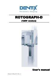
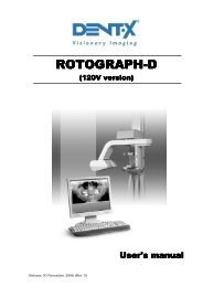
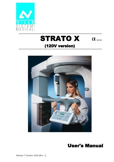
STRATO X 0434<br />
(120V version)<br />
<strong>User</strong>'s <strong>Manual</strong><br />
Release 7 October 2002 (Rev. 1)
USER'S MANUAL<br />
Revision history<br />
Revision history<br />
Rev. Date Page/s Modification description<br />
0 21.02.01 - Document approval.<br />
1 07.10.02 All New intensifying screens.<br />
Integration of Implant description.<br />
Integration of diagnostics for radiological images.<br />
Better description of test.<br />
General improvement of text and pictures.<br />
(Ref. RDM 5419, 5502)<br />
2<br />
3<br />
(Rev. 1)<br />
STRATO X (120V)
USER'S MANUAL<br />
Revision history<br />
THIS PAGE IS INTENTIONALLY LEFT BLANK<br />
STRATO X (120V) (Rev. 1)
USER'S MANUAL<br />
Contents<br />
Contents<br />
1. INTRODUCTION 1<br />
1.1 Icons appearing in the manual................................................................ 1<br />
2. SAFETY INFORMATION 2<br />
2.1 Warnings ................................................................................................ 3<br />
2.2 Environmental risks and displacement ................................................... 5<br />
2.3 Symbols used.......................................................................................... 6<br />
3. CLEANING AND DISINFECTION 7<br />
4. DESCRIPTION 8<br />
4.1 Identification labels and laser labels ....................................................... 8<br />
4.2 Function, Models and Versions ............................................................... 9<br />
4.2.1 Film / Screen combinations...............................................................10<br />
4.2.2 Base version......................................................................................11<br />
4.2.3 Version with cephalometric device......................................................11<br />
4.2.4 Version with Implant examination......................................................12<br />
4.2.5 Version with Implant examination and cephalometric device ..............12<br />
4.3 Parts location........................................................................................ 13<br />
5. TECHNICAL SPECIFICATIONS 15<br />
5.1 Dimensions........................................................................................... 20<br />
5.2 Loading curve of the tube and cooling curve of the anode ..................... 22<br />
5.3 Applied safety relugations ..................................................................... 24<br />
5.4 Note on the “Constant magnification” for Panoramic and TMJ<br />
(close/open mouth) exposures .............................................................. 25<br />
5.5 Measurement method of technical factors (Paragraph for<br />
the authorized personnel) ..................................................................... 26<br />
5.6 Verification method of exposure parameters (Paragraph for<br />
the authorized personnel) ..................................................................... 27<br />
6. GENERAL INSTRUCTIONS FOR USE 31<br />
6.1 Control panel - Descriptions and functions........................................... 31<br />
6.1.1 Key function description ....................................................................34<br />
6.2 “Switching ON” the device ..................................................................... 35<br />
6.3 Positioning of chin support ................................................................... 37<br />
6.4 Panoramic examination ........................................................................ 38<br />
6.4.1 Getting started ..................................................................................38<br />
6.4.2 Anatomic / <strong>Manual</strong> exposure.............................................................40<br />
6.4.2.1 Anatomic exposure ...............................................................41<br />
6.4.2.2 <strong>Manual</strong> exposure..................................................................42<br />
6.4.3 How to prepare the patient.................................................................44<br />
6.4.4 Making an exposure ..........................................................................46<br />
(Rev. 1)<br />
i<br />
STRATO X (120V)
USER'S MANUAL<br />
Contents<br />
6.5 TMJ examination .................................................................................. 51<br />
6.5.1 Getting started .................................................................................. 52<br />
6.5.2 Anatomic / <strong>Manual</strong> exposure............................................................. 53<br />
6.5.2.1 Anatomic exposure............................................................... 54<br />
6.5.2.2 <strong>Manual</strong> exposure.................................................................. 55<br />
6.5.3 TMJ closed mouth............................................................................. 56<br />
6.5.3.1 Preparing the patient............................................................ 56<br />
6.5.3.2 First exposure (Closed mouth) .............................................. 58<br />
6.5.4 TMJ open mouth ............................................................................... 60<br />
6.5.4.1 Preparing the patient............................................................ 60<br />
6.5.4.2 The second exposure (Open mouth) ...................................... 62<br />
6.6 Biaxial temporomandibular joint examination....................................... 65<br />
6.6.1 Getting started .................................................................................. 66<br />
6.6.2 Anatomic / <strong>Manual</strong> exposure............................................................. 67<br />
6.6.2.1 Anatomic exposure............................................................... 68<br />
6.6.2.2 <strong>Manual</strong> exposure.................................................................. 69<br />
6.6.3 How to prepare the patient ................................................................ 70<br />
6.6.4 Making an exposure .......................................................................... 72<br />
6.7 IMPLANT examination........................................................................... 76<br />
6.7.1 Linear tomography programs ............................................................. 78<br />
6.7.1.1 Examination preparation...................................................... 80<br />
6.7.1.2 Anatomical parameters......................................................... 81<br />
6.7.1.3 Tomographic parameters ...................................................... 84<br />
6.7.1.4 Radiographic results ............................................................ 85<br />
6.7.1.5 Right side tomography (quadrants 1 and 4)........................... 86<br />
6.7.1.6 Left side tomography (quadrants 2 and 3) ............................. 87<br />
6.7.2 Positioning of the implant Bite Lock................................................... 88<br />
6.7.2.1 Bite block preparing: Maxilla Implant ................................... 89<br />
6.7.2.2 Bite block preparing: Mandible Implant ................................ 90<br />
6.7.3 Equipment preparation ..................................................................... 91<br />
6.7.4 <strong>Manual</strong> / Anatomic exposure............................................................. 92<br />
6.7.4.1 Anatomic exposure............................................................... 92<br />
6.7.4.2 <strong>Manual</strong> exposure.................................................................. 93<br />
6.7.5 Selection of anatomic and tomographic parameters............................ 94<br />
6.7.6 How to prepare the patient ................................................................ 96<br />
6.7.7 Making an exposure .......................................................................... 99<br />
6.8 Cephalometric examination................................................................. 104<br />
6.8.1 Getting started ................................................................................ 105<br />
6.8.2 Anatomic / <strong>Manual</strong> exposure........................................................... 108<br />
6.8.2.1 Anatomic exposure............................................................. 109<br />
6.8.2.2 <strong>Manual</strong> exposure................................................................ 110<br />
6.8.3 How to prepare the patient .............................................................. 111<br />
6.8.4 Making an exposure ........................................................................ 113<br />
STRATO X (120V) ii<br />
(Rev. 1)
USER'S MANUAL<br />
Contents<br />
6.9 Messages on display ........................................................................... 116<br />
6.10 Research and correction of possible defects in dental radiographies.... 120<br />
6.10.1 Faults due to a wrong positioning of the patient ...............................120<br />
6.10.2 Defects due to wrong data setting and to the dark room ...................121<br />
6.10.3 Defects on film due to the device......................................................121<br />
6.11 Analysis of the problems on the panoramic examinations ................... 122<br />
6.11.1 Proper positioning of the patient ......................................................123<br />
6.11.1.1 Error due to a bad patient's positioning ..............................125<br />
6.11.1.2 <strong>Image</strong>s with artefacts..........................................................132<br />
6.11.1.3 Incorrect film contrast and density .....................................136<br />
6.12 Storing of automatical exposure parameters ....................................... 138<br />
6.12.1 Exposure parameter ........................................................................138<br />
6.12.2 Soft tissue filter ...............................................................................139<br />
6.12.3 Storing parameters ..........................................................................139<br />
6.12.4 Table of pre-set anatomic parameters...............................................140<br />
7. MAINTENANCE 141<br />
This publication can only be reproduced, transmitted, transcribed or translated into<br />
any human or computer language with the written consent of VILLA SISTEMI<br />
MEDICALI S.p.a.<br />
This manual in English is the original version.<br />
(Rev. 1)<br />
iii<br />
STRATO X (120V)
USER'S MANUAL<br />
Contents<br />
THIS PAGE IS INTENTIONALLY LEFT BLANK<br />
STRATO X (120V) iv<br />
(Rev. 1)
USER'S MANUAL<br />
Introduction<br />
1. INTRODUCTION<br />
<br />
NOTE:<br />
The present manual is updated for the product it is sold with in order to<br />
grant an adequate reference to use properly and safely the product.<br />
The manual may not reflect changes to the product not impacting<br />
operating modes or safety.<br />
STRATO X, produced by VILLA SISTEMI MEDICALI Spa, is a X-ray device<br />
for the radiographic analyses of the maxillo-facial complex.<br />
The base version of this device, enables to perform panoramic analyses<br />
and analyses on the temporal-mandibular area, both with open/closed<br />
mouth and with two-axis projection. Fit options are available for<br />
cephalometric and tomographic analyses of the dental arch, particularly<br />
useful in implantation procedures.<br />
The aim of this publication is to instruct the user on the safe and<br />
effective use of the device.<br />
The device must be used complying with the procedures described and<br />
never be used for purposes different from those herewith indicated.<br />
Please read this manual thoroughly before starting using the machine; it<br />
is advisable to keep the manual near the device to refer to it while<br />
operating.<br />
STRATO X is an electro-medical device and it can be used only under the<br />
supervision of a physician or of highly qualified personnel, with the<br />
necessary knowledge on X-ray protection.<br />
The user is liable as concerns legal fulfilment related to the installation<br />
and the operation of the device.<br />
1.1 Icons appearing in the manual<br />
<br />
This icon indicates a NOTE: please read thoroughly the items marked<br />
by this picture.<br />
This icon indicates a WARNING: the items marked by this icon refer to<br />
the safety aspects of the patient and/or of the operator.<br />
(Rev. 1)<br />
1<br />
STRATO X (120V)
USER'S MANUAL<br />
Safety information<br />
2. SAFETY INFORMATION<br />
<br />
WARNING:<br />
Please read this chapter thoroughly.<br />
VILLA SISTEMI MEDICALI designs and builds its devices complying with<br />
the related safety requirements; furthermore it supplies all information<br />
necessary for a correct use and the warnings related to danger associated<br />
with X-rays generating units.<br />
Villa Sistemi Medicali, has not to be held responsible for:<br />
• use of STRATO X different than the intended use,<br />
• damages to the unit, to the operator, to the patient, caused both by<br />
installation and maintenance procedures different than those<br />
described in this manual and in the service manual supplied with the<br />
unit, and by wrong operations,<br />
• mechanical and/or electrical modifications performed during and<br />
after the installation, different than those described in the service<br />
manual.<br />
Installation and any technical intervention must only be performed<br />
by qualified technicians authorised by Villa Sistemi Medicali.<br />
Only the authorised personnel can remove the covers and/or have<br />
access to the components under tension.<br />
STRATO X (120V) 2<br />
(Rev. 1)
USER'S MANUAL<br />
Safety information<br />
2.1 Warnings<br />
This device has not been designed to be used in environments where<br />
vapours, anaestethic mixes flammable with air, or oxygen and nitrous<br />
oxide can be detected.<br />
Avoid pouring water, even accidentally, or other liquids into the device,<br />
as this could cause short-circuits.<br />
Before cleaning the device, please disconnect it from the line voltage.<br />
Wherever necessary, use the fit accessories, such as the leaded aprons,<br />
to protect the patient from radiations.<br />
While performing the radiography, no one, apart from the operator and<br />
the patient, must remain in the room.<br />
STRATO X has been built to support a continuous operation at<br />
intermittent load; therefore please follow the described use cycles to<br />
enable the device cooling down.<br />
Though this unit has been designed with a quite acceptable protection<br />
level from electromagnetic interferences, it is advisable to install it at a<br />
certain distance from electrical energy transformation chambers, from<br />
Uninterruptible Power Supply (UPS) units and from receivingtransmitting<br />
units for amatoeurial use. Cellular telephones are only<br />
admitted at a distance of more than 1,5 mt from any component of the<br />
device.<br />
Other medical instruments and devices that must be used in the same<br />
installation area of the unit must comply the Electromagnetic<br />
Compatibility rules in force. Non-complying instruments, of which the<br />
poor immunity from electromagnetic fields is well known, must be<br />
installed at least 3 mt far from the STRATO X and supplied by a different<br />
electrical line.<br />
STRATO X must be off while using devices such as electrical lancets or<br />
the like.<br />
Please clean and disinfect, when necessary, all parts that can be in<br />
contact with the patient.<br />
Never try to rotate the moving arm manually when the unit is<br />
switched on, to avoid permanent damage to the unit.<br />
After use, please replace the bite and the ear-centring devices.<br />
(Rev. 1)<br />
3<br />
STRATO X (120V)
USER'S MANUAL<br />
Safety information<br />
Though the X-ray quantity supplied by dental X-ray units is quite low<br />
and distributed on a small surface, the operator must adopt the<br />
precautions and/or fit protections for the patient and himself, during the<br />
execution of radiography. It is advisable to control the X-ray emission<br />
from a protected area, by means of a remote control. If it is necessary to<br />
operate near the patient, stay as far as the cable of the remote control<br />
allows it, or at least 1,5 m far both from the X-ray source and from the<br />
patient, as shown in the Figure 1 and Figure 2.<br />
Figure 1 - Panoramic version<br />
Figure 2 - Cephalometric version<br />
STRATO X (120V) 4<br />
(Rev. 1)
USER'S MANUAL<br />
Safety information<br />
<br />
WARNING: PRECAUTIONS WHILE USING LASER CENTRING<br />
DEVICE:<br />
• Keep always an adequate illumination in the room.<br />
• Do not look into the output windows of laser centering units.<br />
• Do not stare at the reflections of laser pointers.<br />
• Instruct the patient to keep his/her eyes closed as long as the laser<br />
pointers are active.<br />
• Before starting an examination, the patient must remove earrings,<br />
glasses, necklaces and whatever else could reflect the laser beam or<br />
be impressed on the radiographic image.<br />
• Do not clean the openings of laser centring devices with tools that<br />
could modify the optics. Necessary cleaning must be performed only<br />
by authorised technicians.<br />
Operations different than those indicated could cause the ejection of<br />
dangerous non-ionising radiations.<br />
<br />
NOTE:<br />
When the unit is on, do not move manually the rotating arm or the<br />
tubehead (part 2a of Figure 4).<br />
2.2 Environmental risks and displacement<br />
The device contains in some of its parts, materials and liquids that at the<br />
end of the units life, must be disposed of at the fit disposal centers.<br />
Particularly the device contains the following materials and/or<br />
components:<br />
• Tubehead: dielectric oil, lead, copper, iron, aluminium, glass,<br />
tungsten, beryllium.<br />
• Control panel and Remote control: iron, copper, aluminium, glassresin,<br />
non-biodegradable plastic material packaging.<br />
• Column, Rotating arm and Extensions: iron, lead, aluminium,<br />
copper, glass-resin, and non-biodegradable plastic material.<br />
<br />
NOTE:<br />
VILLA SISTEMI MEDICALI is not responsible for the disposal of the<br />
device performed by the user and for the related costs.<br />
(Rev. 1)<br />
5<br />
STRATO X (120V)
USER'S MANUAL<br />
Safety information<br />
2.3 Symbols used<br />
In this manual and on the STRATO X itself, apart from the symbols<br />
indicated on the control panel, also the following icons are used:<br />
Symbol<br />
Description<br />
Device with type B applied parts<br />
∼<br />
N<br />
L<br />
A.C.<br />
Connection point to the neutral conductor<br />
Connection point to the line conductor<br />
Protection grounding<br />
Operation grounding<br />
OFF ; device not connected to the mains<br />
ON ; device connected to the mains<br />
Laser<br />
Laser source output<br />
Dangerous voltage<br />
Activation of cephalometry ear-set rods<br />
0434<br />
Conformity to the CE 93/42 Directive<br />
STRATO X (120V) 6<br />
(Rev. 1)
USER'S MANUAL<br />
Safety information<br />
3. CLEANING AND DISINFECTION<br />
In order to get an accurate hygene and cleaning it is necessary to follow<br />
thoroughly all indicated procedures.<br />
<br />
WARNING:<br />
Disconnect the unit from the mains<br />
before performing any cleaning.<br />
Do not let water or liquids enter the unit, these could cause corrosion or<br />
short-circuits.<br />
Use only a wet cloth and a mild<br />
detergent to clean the painted<br />
surfaces, the accessories and the<br />
connection cables, and wipe then<br />
with a dry cloth; do not use<br />
solvents (alcohol, benzine, trichloroethylene)<br />
nor corrosive and abrasive<br />
solutions.<br />
To clean the rare earths scintillating screens in the cassette, please follow<br />
the indication given by its manufacturer, do not use, detergents, solvent<br />
(alcohol, benzine), corrosive or abrasive stuffs.<br />
The bite-holding rod, the centring bite and the ear centring units of<br />
the cephalostatus must be replaced after each examination.<br />
Clean thoroughly the chin rest, the handles, the nose-rest and the<br />
temple-support any time these are used.<br />
It is advisable to disinfect, whenever necessary, the chin-rest, the<br />
handles, the nose-rest and the temple support with a 2% Glutaraldehyde<br />
solution or similar (find out what is available; e.g. Milton).<br />
(Rev. 1)<br />
7<br />
STRATO X (120V)
USER'S MANUAL<br />
Cleaning and disinfection<br />
4. DESCRIPTION<br />
4.1 Identification labels and laser labels<br />
7<br />
4-5<br />
6<br />
3<br />
2<br />
1<br />
1a<br />
STRATO X<br />
Identification label<br />
Figure 3<br />
1b<br />
ETL certification label<br />
2<br />
Tubehead<br />
Identification label<br />
3<br />
Laser<br />
warning<br />
label<br />
4<br />
(N° 2) Laser<br />
symbol label<br />
5<br />
(N° 2) Spot laser<br />
identification<br />
label<br />
6<br />
Cephalometric device<br />
identification label (Optional)<br />
7<br />
Warning label<br />
STRATO X (120V) 8<br />
(Rev. 1)
USER'S MANUAL<br />
Safety information<br />
4.2 Function, Models and Versions<br />
STRATO X, produced by VILLA SISTEMI MEDICALI Spa is a complete<br />
ortopantomographic device, which enables to perform all radiographies<br />
commonly necessary in dental field.<br />
In some versions, certain examination modes are not available but the<br />
device (thanks to its computerised control system) can be expanded and<br />
updated with new releases, directly at the Dentist premises.<br />
The cassettes used for all examinations are flat.<br />
For cephalometry the following cassette sizes are available: 8"x10"<br />
(supplied with the machine as standard accessory) and 10"x12" (to be<br />
requested when ordering the machine).<br />
For all other exams the size is unique and corresponds to 15x30 cm.<br />
The versions available are:<br />
• Standard version (for panoramic examinations and examinations on<br />
the Temporal-Mandibular Joint - TMJ).<br />
• Version with device for Cephalometry.<br />
• Version with Implant examination.<br />
• Version with Implant examination and device for Cephalometry.<br />
(Rev. 1)<br />
9<br />
STRATO X (120V)
USER'S MANUAL<br />
Cleaning and disinfection<br />
4.2.1 Film / Screen combinations<br />
To get a good image quality, it is advisable to match the intensifying<br />
screens and the films, as indicated hereafter:<br />
Supplier Films Sensibility Screen<br />
KONIKA MG Verde KR II<br />
KONIKA MGH Verde KR II<br />
KODAK T-MAT G/RA Verde Lanex Regular<br />
AGFA HTA Verde Medium<br />
FUJI HR-G Verde G8<br />
IMATION XDA Verde T 16<br />
KODAK T-MAT G/RA Verde Lanex Medium<br />
STERLING ULTRAVISION Blu Ultravision Rapid<br />
Table 1<br />
<br />
NOTE:<br />
It is advisable to use always films and screens of the same brand.<br />
Combinations of films and screen of different manufacturer are possible<br />
so long as the same sensitivity is maintained. Never combine films and<br />
screens with different sensibility (green and blue).<br />
The factory set values of the exposure factors listed in paragraph 6.12.4,<br />
as default, are indicative and optimised for the combination film/screen<br />
supplied with the device (film T-MAT G/RA and screens Lanex Regular or<br />
film KONICA MG and KONICA screens). For the other combinations listed<br />
in the table or for further combinations, the exposure factors have to be<br />
modified accordingly by acting as described in paragraph 6.12.<br />
The real adjustment of these values depends on different conditions such<br />
as the preference of the user for much or less exposed images.<br />
The quality of the image, therefore, does not exclusively depend on<br />
STRATO X but it is also extremely important to pay attention to the<br />
processing procedure of the films and the materials related<br />
<br />
NOTE:<br />
Perform the maintenance of the film processor as described in the related<br />
instruction manual.<br />
Regularly check the levels of the used chemical substances; replace them<br />
regularly as indicated by the manufacturer (or according to the number<br />
of processed films).<br />
STRATO X (120V) 10<br />
(Rev. 1)
USER'S MANUAL<br />
Safety information<br />
4.2.2 Base version<br />
The base version (cod. 9309001311) enables to perform the following<br />
examinations:<br />
• Panoramic - Children and Adults - 3 Sizes and 3 arches: for 18<br />
combination in Automatic selection. In manual mode, it is<br />
possible to vary the voltage from 50 kV to 80 kV, in 2kV steps<br />
and the anode current from 4 mA to 10mA in 1mA steps. This<br />
function also allows the examination of half mouth (emipanoramic<br />
right and left). All examination are performed with a<br />
"constant magnification" factor of 1.23.<br />
• Examination of the Temporal-Mandibular joint (TMJ) with<br />
closed and open mouths for Children and Adults in 3 sizes and<br />
3 arcs for a total of 18 combination in automatic selection; in<br />
<strong>Manual</strong> mode it is possible to vary the voltage from 50 kV to 80<br />
kV, in 2kV steps and the anode current from 4 mA to 10mA in<br />
1mA steps.<br />
• Examination of the Temporal-Mandibular joint – biaxial (biaxial<br />
TMJ) for adult and children in 3 sizes: for 6 combination in<br />
automatic mode. In manual mode, it is possible to change the<br />
voltage from 50 kV to 80 kV, in 2kV steps and the anode<br />
current from 4 mA to 10mA in 1mA steps.<br />
The machine is ready to be equipped with the following functions:<br />
• Cephalometric device with related examination mode.<br />
• Implant examination.<br />
4.2.3 Version with cephalometric device<br />
The version with cephalometric device (cod. 9309002311) enables to<br />
perform the following examinations:<br />
• Panoramic, TMJ and TMJ biaxial with the same characteristics<br />
described for the standard version.<br />
• Cephalometry for Adult and Children with 3 Sizes for up to 6<br />
combinations in automatic selection. The manual mode enables to<br />
change the voltage from 60kV to 80kV in 2kV steps, and the anode<br />
current from 4mA to 12mA in 1mA steps. The examinations are<br />
performed on flat cassettes which size is 8"x10" or 10"x12". The<br />
selection of collimators occurs automatically according to the used<br />
cassette and to the chosen projection; the Soft Tissues Filter (STF) is<br />
motorised and can be adjusted to get the best projection of the face<br />
profile.<br />
The machine can be also equipped with the following function:<br />
• Implant examination.<br />
(Rev. 1)<br />
11<br />
STRATO X (120V)
USER'S MANUAL<br />
Cleaning and disinfection<br />
4.2.4 Version with Implant examination<br />
The version with Implant examination (cod. 9309003311) enables to<br />
perform the following examinations:<br />
• Panoramic, TMJ and TMJ biaxial with the same characteristics<br />
described for the standard version.<br />
• Implant for Adult with 3 Sizes in automatic selection. The manual<br />
mode enables to change the voltage from 50kV to 80kV in 2kV steps,<br />
and the anode current from 4mA to 10mA in 1mA steps. The<br />
examinations are performed on flat cassettes which size 15x30 cm.<br />
The selection of the proper collimator is automatic.<br />
The machine is ready to be equipped with the following function:<br />
• Cephalometric device with related examination mode.<br />
4.2.5 Version with Implant examination and cephalometric device<br />
The version with Implant examination and Cephalometric device (cod.<br />
9309004311) enables to perform the following examinations:<br />
• Panoramic, TMJ and TMJ biaxial with the same characteristics<br />
described for the base version.<br />
• Cephalometry as described in paragraph 4.2.3.<br />
• Implant as described in paragraph 4.2.4.<br />
<br />
NOTE:<br />
Implant and/or Cephalometric options can be added to existing units at<br />
any time.<br />
STRATO X (120V) 12<br />
(Rev. 1)
USER'S MANUAL<br />
Safety information<br />
4.3 Parts location<br />
2<br />
5<br />
3<br />
30<br />
2a<br />
4<br />
1<br />
1a<br />
Figure 4<br />
1 - Column with base equipped with electrical power part and cursor<br />
with motorised vertical movement. The column must be fixed at the<br />
wall by 4 dowels, two fixing the upper part and two fixing the lower.<br />
The front part of the column is equipped with an housing closed by<br />
two covers, within which it is possible to set 4 trays (1a) containing<br />
the consumables (bites, rods, etc.) and options (supports, etc.).<br />
2 - X, Y axes movement unit and rotation support, (CPU board) with<br />
rotating arm equipped with: HF tubehead with power supply board<br />
(2a), automatic primary collimator, soft tissues filter (STF) and laser<br />
centering devices.<br />
(Rev. 1)<br />
13<br />
STRATO X (120V)
USER'S MANUAL<br />
Cleaning and disinfection<br />
3 - Cassettes holder for all functions (apart from cephalometry) with flat<br />
standard cassette 15x30 cm.<br />
4 - Chin support arm equipped with: control keyboard, temple support,<br />
chin-rest, centring bite and handles. The control panel is equipped<br />
with a soft-key keyboard, indication LED for the selected functions<br />
and an alphanumeric two-row display for all technical, operative<br />
and warning messages.<br />
5 - Cephalometric arm (optional) including cephalometric device,<br />
cassette support (with laser alignment pointer directly from the<br />
rotating arm) positioned on the left of the column.<br />
30 - X-ray push button equipped with extensible cable, which allows the<br />
user to operate the unit from proper distance as required by the<br />
safety rules.<br />
STRATO X (120V) 14<br />
(Rev. 1)
USER'S MANUAL<br />
Technical specifications<br />
5. TECHNICAL SPECIFICATIONS<br />
General features<br />
Type<br />
Manufacturer<br />
Class<br />
Protection degree<br />
STRATO X<br />
VILLA SISTEMI MEDICALI<br />
Buccinasco (MI) Italia<br />
Class II according to 21CFRsubchapter<br />
J.<br />
Class II B for European Directive<br />
for Medical Devices 93/42.<br />
Class I with type B applied parts<br />
according to IEC 601-1<br />
IP20<br />
Rated line voltage 120V∼ ±10%<br />
Line frequency<br />
60Hz<br />
Maximum line current 15A (at 108V, 80kV, 12mA - see Note 1)<br />
Power consumption<br />
2 kVA<br />
Protection fuse (F2)<br />
15A F<br />
Transformer protection fuse T1 (F1) 0.8A T<br />
Controls supply protection fuse (F5) 0.5A T<br />
Column motor protection fuse (F3, F4) 7A T<br />
Line voltage regulation
USER'S MANUAL<br />
Technical specifications<br />
Exposure time<br />
Panoramic (PAN)<br />
Emi Panoramic<br />
TMJ open/closed mouth<br />
TMJ biaxial<br />
Implant<br />
Cephalometry (Ceph)<br />
15 s PAN Adult / 13.5 s PAN Child<br />
8 s Adult / 8 s Child<br />
5.3 s per image for left and right joint in<br />
open and closed condition (11 s total<br />
time)<br />
10.8 s (total time)<br />
3.4s (minimum) - 11.4 s (maximum) for<br />
4 images<br />
0.2 ÷ 3 s<br />
Exposure time accuracy ± 10 %<br />
Examination programs<br />
Examination selection • Automatic selection for Adult and<br />
Child, 3 sizes, 3 arches (in Panoramic<br />
and TMJ)<br />
• Automatic selection for Adult and<br />
Child, 3 sizes (in biaxial TMJ)<br />
• Automatic selection for Adult, 3 sizes,<br />
3 arches (in Implant)<br />
• <strong>Manual</strong> selection<br />
• Collimator with automatic positioning<br />
Panoramic • Standard Panoramic<br />
• Emi Panoramic<br />
TMJ (Temporal Mandibular Joint) • TMJ open and closed mouth<br />
• TMJ biaxial<br />
Implant • 2 slices (one longitudinal and one<br />
transversal)<br />
• 4 slices (one longitudinal and three<br />
transversal)<br />
Cephalometry • Cassette 8" x 10" for Latero-Lateral<br />
and Antero-Posterior or Posterior-<br />
Antero.<br />
• Cassette 12" x 10" for Latero-Lateral.<br />
• Soft Tissues filter adjustable by<br />
motorized movement.<br />
STRATO X (120V) 16<br />
(Rev. 1)
USER'S MANUAL<br />
Technical specifications<br />
<strong>Image</strong> magnification<br />
PAN and TMJ open/closed mouth<br />
Implant<br />
CEPH<br />
No. of images in TMJ (open/closed<br />
mouth and biaxial)<br />
Tubehead characteristics<br />
Model MS 05<br />
Manufacturer<br />
Maximum tube voltage<br />
1 : 1.23 (constant)<br />
1 : 1.37 (constant)<br />
1 : 1.1 (average)<br />
4<br />
Villa Sistemi Medicali S.p.A.<br />
20090 Buccinasco (MI) Italia<br />
80 kVp<br />
kVp accuracy ± 8 %<br />
Max. anodic current<br />
12 mA<br />
Anodic current accuracy ± 10 %<br />
Duty cycle 1 : 16<br />
Nominal power<br />
Total filtration<br />
HVL (Half value layer)<br />
Transformer insulation<br />
Cooling<br />
Leakage radiation at 1 m<br />
Reference time current product<br />
X-ray tube characteristics<br />
Manufacturer<br />
0.96 kW (80 kVp - 12 mA)<br />
2.5 mm Al eq. @ 70 kVp<br />
>2.5mm Al eq. @ 80kVp<br />
Oil bath<br />
By convection<br />
Type OPX 105<br />
< 0.5 mGy/h @ 80 kVp - 12 mA - 3 s duty<br />
cycle 1/16<br />
1.2 mAs (6mA for 200msec)<br />
CEI Bologna (Italia)<br />
Nominal focal spot 0.5 IEC 336<br />
Inherent filtration<br />
Anode tilt 5°<br />
Anode material<br />
Nominal maximum voltage<br />
Filament max current<br />
Filament max voltage<br />
Anode thermal capacity<br />
0.5 mm Al eq.<br />
Tungsten<br />
105 kVp<br />
4 A<br />
8 V<br />
30 kJ<br />
(Rev. 1)<br />
17<br />
STRATO X (120V)
USER'S MANUAL<br />
Technical specifications<br />
Laser centering devices<br />
3 laser beams are used for the patient positioning; beams align mid Sagittal,<br />
Frankfurt and Canine Planes (please refer to relevant paragraphs for detailed<br />
explanation).<br />
Wave length<br />
Optical power of laser diode<br />
Optical power of the collimed beam<br />
Divergence<br />
Optical power on the working surface<br />
Laser class<br />
DNRO in 30 s application period<br />
Mechanical characteristics<br />
Focus-film distance (PAN, TMJ and<br />
Implant)<br />
Film size (PAN, TMJ and Implant)<br />
Focus film distance (CEPH)<br />
Film size (CEPH)<br />
Telescopic motorized column run<br />
Total height max.<br />
635 nm<br />
5 mW<br />
4.5 nW<br />
6.67 mRad<br />
< 3 mW<br />
3 A<br />
0.05 m<br />
20" (51 cm)<br />
15x30 cm flat cassette<br />
65" (165 cm)<br />
8"x10" (18x24 cm) and<br />
10"x12" (24x30 cm)<br />
26.4" (67 cm)<br />
91.3" (232 cm)<br />
Width x Length • 39.4" x 49.2" (100 x 125 cm) base<br />
machine<br />
• 69.7" x 49.2" (177 x 125 cm) with<br />
Ceph<br />
Weight • 135 kg base machine<br />
• 150 kg with Ceph<br />
Column weight<br />
Weight of arm support, rotating arm and<br />
tubehead<br />
Cassette holder weight<br />
Weight of the chin rest arm<br />
72 kg<br />
48 kg<br />
7 kg<br />
8 kg<br />
STRATO X (120V) 18<br />
(Rev. 1)
USER'S MANUAL<br />
Technical specifications<br />
Environmental features<br />
Working area (please refer to paragraph<br />
5.3 of the Service <strong>Manual</strong>)<br />
Minimum height ceiling (please refer to<br />
paragraph 5.3 of the Service <strong>Manual</strong>)<br />
• 51.2"x51.2" (130x130 cm) base<br />
machine<br />
• 74.8"x51.2" (190x130 cm) with Ceph<br />
98.5" (250 cm)<br />
Temperature in working condition + 10° ÷ + 40°<br />
RH (related humidity) in working<br />
condition<br />
30% ÷ 75%<br />
Temperature for transport and storing - 20° ÷ + 70°<br />
Humidity for transport and storing<br />
Min. atmospheric pressure for transport<br />
and storing<br />
< 95% without condense<br />
630 hPa<br />
(Rev. 1)<br />
19<br />
STRATO X (120V)
USER'S MANUAL<br />
Technical specifications<br />
5.1 Dimensions<br />
Figure 5 - Base version<br />
STRATO X (120V) 20<br />
(Rev. 1)
USER'S MANUAL<br />
Technical specifications<br />
Figure 6 - Version equipped with cephalometric unit<br />
(Rev. 1)<br />
21<br />
STRATO X (120V)
USER'S MANUAL<br />
Technical specifications<br />
5.2 Loading curve of the tube and cooling curve of the<br />
anode<br />
Tube "CEI - OPX/105" (0.5 IEC 336)<br />
Load<br />
Anode cooling curve<br />
STRATO X (120V) 22<br />
(Rev. 1)
USER'S MANUAL<br />
Technical specifications<br />
Cooling curve of Tubehead<br />
E(KJ)<br />
350<br />
300<br />
250<br />
200<br />
150<br />
100<br />
50<br />
0<br />
0 100 200 300 400 500<br />
min<br />
(Rev. 1)<br />
23<br />
STRATO X (120V)
USER'S MANUAL<br />
Technical specifications<br />
5.3 Applied safety relugations<br />
STRATO X complies with the following standard:<br />
FDA 21 CFR chapter J<br />
CE 93/42<br />
• General safety:<br />
IEC 601-1 and UL 2601-1<br />
IEC 601-1-1<br />
IEC 601-2-7<br />
IEC 601-2-28<br />
• Electromagnetic compliance:<br />
IEC 601-1-2<br />
• Protection against radiations:<br />
IEC 601-1-3<br />
IEC 825-1<br />
0434 The symbol CE grants that STRATO X complies with<br />
directives 93/42 for medical devices issued by the European<br />
Community.<br />
Classifications<br />
STRATO X is an electro-medical X-ray device belonging to Class I type B<br />
as per classifications IEC 601-1, foreseen for a continuous working at<br />
intermittent load.<br />
According to CE 93/42 Directives for medical devices, the equipment<br />
belongs to class II B.<br />
According to FDA 21 CFR, the equipment belongs to class II.<br />
STRATO X (120V) 24<br />
(Rev. 1)
USER'S MANUAL<br />
Technical specifications<br />
5.4 Note on the “Constant magnification” for<br />
Panoramic and TMJ (close/open mouth) exposures<br />
<br />
NOTE:<br />
STRATO X is based on a dentition and ascending rami shape as defined<br />
by U. Welander et al., Dentomaxillofacial Radiology, 1989, Vol. 18, May.<br />
This paper, based on statistic study, enstabilishes a form for the<br />
dentomaxillofacial complex that it is assumed as "standard". A projection<br />
geometry that maintains a constant magnification of 1.23 throughout the<br />
exposure of this shape has been applied to the STRATO X. Patient’s<br />
anatomy can differ in a significant way from the statistical model, so the<br />
magnification factor is not maintained and can be different from that<br />
value. Based on his experience and competence, the user has to judge<br />
this variation.<br />
IN ANY CASE, THE PANORAMIC RADIOGRAPHY CANNOT BE USED<br />
TO PERFORM CALCULATIONS OF DISTANCES, ANGLES ETC. ON<br />
THE FILM.<br />
(Rev. 1)<br />
25<br />
STRATO X (120V)
USER'S MANUAL<br />
Technical specifications<br />
5.5 Measurement method of technical factors<br />
(Paragraph for the authorized personnel)<br />
<br />
WARNING:<br />
These measurements require the removal of the HF group covers; this<br />
means to gain access to internal parts where high voltage are normally<br />
present.<br />
For the measurement of the exposure parameters with the invasive<br />
method, please follow the procedure described in paragraphs 7.2 and 7.3<br />
of the Service manual.<br />
<br />
WARNING:<br />
During the panoramic examination, the set value of kV and tube current<br />
varies according to a pre-determined curve in order to compensate the<br />
different absorption of X-ray beam due to different anatomical structures.<br />
In this way, it is possible to obtain a good uniformity of the image’s<br />
contrast. Particularly, the chosen value is lowered on the initial phase of<br />
the panoramic and increased on the scissors/canine zone, in order to<br />
compensate the effect of the cervical spine.<br />
The value displayed during the panoramic examination corresponds to<br />
the to chosen one, while the instantaneous value can be different; these<br />
effects must be considered in case of measure of the exposure factors<br />
using standard diagnostic mode (please refer to the note at page 51).<br />
Accuracy declared on the section "Technical data" is referred to the<br />
actual value of kV and/or mA. In any case, manufacturer guarantees<br />
that the accuracy of loading factors is always compliance with the<br />
international standard for safety of medical devices IEC 601-1.<br />
Particularly, in accordance with IEC 601-2-7, the maximum deviation<br />
(including the correction and instrument’s accuracy) is less than or equal<br />
to ±10 for kV, while for tube current is less than or equal to ±15%.<br />
STRATO X (120V) 26<br />
(Rev. 1)
USER'S MANUAL<br />
Technical specifications<br />
5.6 Verification method of exposure parameters<br />
(Paragraph for the authorized personnel)<br />
The exposure parameters can also be checked using the so called "noninvasive<br />
method". This method requires the use of a specific instrument,<br />
identified as a "probe" in Figure 7.<br />
<br />
NOTE:<br />
The instruments normally used for the measurement of the exposure<br />
parameters (kVp) with the non-invasive method, have an intrinsic<br />
measurement non-linearity when used to measure low dose radiations.<br />
This non-linearity can lead to measuring errors clearly not due to the<br />
STRATO X.<br />
As example, please see the next diagram where the sensitivity curve of a<br />
normal measuring instrument is shown. Working outside the dark area,<br />
the instrument is not linear.<br />
The exposure parameters can be checked with a non-invasive instrument<br />
by performing the following procedure:<br />
1. With the unit on, select the Panoramic examination mode by pressing<br />
key "17" .<br />
(Rev. 1)<br />
27<br />
STRATO X (120V)
USER'S MANUAL<br />
Technical specifications<br />
2. Press keys "10" , "28" and "24" at the same<br />
time. LED’s of "patient type", "patient size" and "Arch" switch<br />
off and the display shows the following two messages alternatively:<br />
and<br />
R E M O V E<br />
C H I N R E S T<br />
C L O S E<br />
T E M P L E S U P P O R T<br />
<br />
NOTE:<br />
The following operations is a confirmation that the above points have<br />
been performed.<br />
3. Carry out the actions mentioned above; press key "23" ;<br />
the unit will carry out a movement to reach the "zero" position.<br />
During this phase, the display shows:<br />
P L E A S E W A I T . . .<br />
Once the "zero" position is reached, the display will show the<br />
following message:<br />
O P E N<br />
C A S S E T T E U N I T<br />
4. After opening the cassette holder to Ceph position (this action is<br />
sensed by the unit which monitors the status of microswitches S25),<br />
the display shows:<br />
P L E A S E W A I T . . .<br />
In the mean time, the unit sets the primary collimator to position<br />
8"x10" symmetric (Slot #5) and the soft tissue filter in position "not in<br />
field"; at the end of the positioning phase, the display shows:<br />
R X P A R A M E T E R S<br />
7 0 k V 0 8 m A 1 . 0 0 S<br />
STRATO X (120V) 28<br />
(Rev. 1)
USER'S MANUAL<br />
Technical specifications<br />
5. Place the measuring instrument over the chin support as shown in<br />
Figure 7.<br />
6. Acting on key "4" and "7" and on keys "3" or<br />
"6" set the exposure parameters to carry out the desidered<br />
checks.<br />
The variation range of the parameters is shown in the following table<br />
(see also NOTE at page 27):<br />
Parameter Minimum value Maximum value<br />
kV 50 80<br />
s 0,2 15<br />
Table 2<br />
<br />
NOTE:<br />
Acting on key "5" and then on keys "3" or "6" the<br />
mA value can be changed.<br />
The mA value ranges from 4 to 12 (1 mA step).<br />
PROBE<br />
Figure 7<br />
(Rev. 1)<br />
29<br />
STRATO X (120V)
USER'S MANUAL<br />
Technical specifications<br />
<br />
WARNING:<br />
X-ray will be emitted during the execution of the following operations.<br />
Authorised technicians are therefore recommended to use the greatest<br />
caution and to comply with the safety regulations and laws of the of their<br />
country.<br />
7. Perform an exposure; the emitted parameters (kV and Time) can be<br />
read on the measuring instrument.<br />
<br />
NOTE:<br />
The performances are guaranteed if the measurement of kV and it is<br />
done with the invasive method.<br />
To quit this routine, press key "9"<br />
; the display will show:<br />
C L O S E C A S S E T T E<br />
T O P A N O R A M I C<br />
After closing the cassette holder to Panoramic position (the position is<br />
sensed by the unit through microswitch S24), the display will show the<br />
following message:<br />
P R E S S E N T E R<br />
Press key "23"<br />
; the unit will carry out the zeroing and will set<br />
itself in the patient entry position; the display will first show:<br />
P L E A S E W A I T . . .<br />
then<br />
x x k V x x m A 1 5 . 0 s<br />
and the unit returned at a standard mode.<br />
STRATO X (120V) 30<br />
(Rev. 1)
USER'S MANUAL<br />
General instructions for use<br />
6. GENERAL INSTRUCTIONS FOR USE<br />
6.1 Control panel - Descriptions and functions<br />
STRATO X keyboard is divided into 8 functional areas, and a display to<br />
view the messages and the error codes.<br />
Next figure shows a general view of the keyboard, while details an each<br />
functional area are provided in the following pages.<br />
Signal LEDs<br />
Anatomical selection<br />
Luminous<br />
centering<br />
devices<br />
Command<br />
confirm.<br />
LED<br />
Carriage<br />
movement<br />
(canine<br />
plane)<br />
Exam.<br />
setting<br />
key<br />
Control keys<br />
Examination mode selection<br />
Column movement<br />
Exposure parameters<br />
manual selection<br />
Figure 9<br />
(Rev. 1)<br />
31<br />
STRATO X (120V)
USER'S MANUAL<br />
General instructions for use<br />
Reserved for future<br />
Implant<br />
settings<br />
Cephalometric<br />
Each key enables the selection of a<br />
specific examination. The pre-set<br />
examinations are:<br />
Panoramic – TMJ open/closed mouth,<br />
TMJ biaxial, Implant, Cephalometry.<br />
TMJ open/closed<br />
mouth<br />
Biaxial TMJ Panoramic<br />
It is possible to select the examinations<br />
automatically (anatomic selection)<br />
using pre-fixed exposure values. This<br />
kind of selection enables to choose<br />
between Adult/Child, each with three<br />
different sizes (small, medium, large);<br />
for Panoramic, TMJ open/closed<br />
mouth, and Implant there is the<br />
possibility to chose among three<br />
different dental arches.<br />
Large<br />
Medium<br />
Narrow<br />
In panoramic and TMJ examination<br />
mode, the system allows the selection of<br />
the type of the dental arch.<br />
The arch key allows the selection<br />
among 3 different mouth<br />
conformations: narrow - medium -<br />
large.<br />
The selection made is confirmed by the<br />
activation of the corresponding LED.<br />
The arch selection does not influence<br />
the values of kV and mA but acts on<br />
the position of the focus layer.<br />
Furthermore there is the possibility to<br />
select manually the exposure<br />
parameters; in this case select at first<br />
the parameter to be changed and<br />
secondly, using the increasing and<br />
reducing keys, set the required value.<br />
The parameters available are: kV, mA<br />
and time. The latter just for<br />
cephalometry.<br />
STRATO X (120V) 32<br />
(Rev. 1)
USER'S MANUAL<br />
General instructions for use<br />
This area contains the keys which control<br />
the tubehead arm movements (canin<br />
plane) during the patient positioning, and<br />
the relevant confermation key. When the<br />
"Command confirmation LED" is lit, it<br />
means that<br />
the key<br />
, must be pressed to<br />
Command<br />
confirm.<br />
LED<br />
Setting<br />
key<br />
confirm the selected command.<br />
There are two light indicators; the first<br />
one on the left indicates the condition<br />
"Machine Ready", indicating the user that<br />
by pressing the X-ray button key once<br />
more, X-rays emission will start; the<br />
second led indicates the emission of<br />
X-rays.<br />
The movement of the column is<br />
controlled by the related keys; for<br />
safety’s sake, this control is performed<br />
pressing two keys at the same time,<br />
the central one and one of the two<br />
lateral.<br />
The left button is dedicated to the center<br />
of sagittal, canine and Frankfurt planes,<br />
thus adapting the STRATO X to the<br />
patient anatomy.<br />
The right button is reserved for future<br />
use.<br />
Apart from the keys dedicated to the<br />
selection of the examination functions,<br />
part of the STRATO X keyboard is<br />
dedicated to the services. From left to<br />
right, we have: the "Test" key (which<br />
disables the X-ray emission during<br />
arm rotation), the "Reset" key (to be<br />
pressed after the unwanted release of<br />
the X-ray push button "30" during<br />
exposure) and the "Arm return" (to<br />
prepare the system for the next<br />
examination).<br />
(Rev. 1)<br />
33<br />
STRATO X (120V)
USER'S MANUAL<br />
General instructions for use<br />
6.1.1 Key function description<br />
Figure 10 - Control panel<br />
LEGEND:<br />
Messages<br />
Display: indicates operative messages, warnings and<br />
exposure parameters.<br />
Signal lights<br />
1 - Led indicating the machine is ready for X-ray<br />
emission (green LED)<br />
2 - Yellow LED indicating X-rays emission<br />
<strong>Manual</strong> setting of exposure parameters<br />
3 - kV, s or mA increasing<br />
4 - Seconds<br />
5 - milliAmpere<br />
6 - Reduction of kV, s or mA<br />
7 - KVolt<br />
Preparation functions<br />
8 - Key to set Test function<br />
9 - Reset, axes alignment and enabling to modify<br />
exam modes<br />
10 - Positioning of the rotation unit to start the<br />
selected examination or return of the unit for a<br />
new setting<br />
Anatomic selection<br />
11 - Adult or Child (green LED)<br />
12 - Small, medium or large size (green LED)<br />
13 - Wide, normal or narrow arch (for Panoramic,<br />
TMJ and Implant exposure) (green LED)<br />
Examination mode<br />
14 - Implant (Optional)<br />
15 - Cephalometry (Optional)<br />
16 - Reserved for future settings<br />
17 - Panoramic<br />
18 - TMJ closed mouth – open mouth<br />
19 - TMJ biaxial<br />
Centring devices<br />
20 - Saggital, Frankfurt and Canine Plane centring unit<br />
21 - Button not active<br />
Patient centring<br />
23 - Enter key<br />
22, 24, 25 and 26 - These buttons have different actions<br />
depending on the examination<br />
selected; refer to relevant<br />
paragraphs<br />
Height adjustment<br />
27 + 28 - Column up<br />
29 + 28 - Column down<br />
STRATO X (120V) 34<br />
(Rev. 1)
USER'S MANUAL<br />
General instructions for use<br />
6.2 “Switching ON” the device<br />
Press the green button on the base of the column to switch the system<br />
on. The LED on the control panel and the following display message,<br />
indicate an auto-diagnosis is on the run:<br />
S T R A T O X<br />
R E L E A S E * . * *<br />
After 3 seconds, the display shows the following message:<br />
> T E S T <<br />
<br />
NOTE:<br />
During this phase, STRATO X does not perform any movement, it just<br />
performs a series of checks which, in case of negative result, could<br />
require the intervention of the technician.<br />
The only problem that can be solved by the user is related to the position<br />
of the cassette holder PAN; in this case, the following message will be<br />
displayed:<br />
C L O S E C A S S E T T E<br />
T O P A N O R A M I C<br />
Once the auto-diagnosis is complete, the LED of the confirmation request<br />
button will light; press "23"<br />
key to start the alignment phase of<br />
motors; while waiting the display will show the following message:<br />
M A C H I N E S E T T I N G<br />
Once ENTER has been pressed, the related LED goes OFF and the<br />
display shows the following message during the alignment of axes:<br />
W A I T F O R<br />
M A C H I N E S E T T I N G<br />
<br />
WARNING:<br />
During this phase, the machine checks for possible obstacles that may<br />
create collisions simulating the movements performed during the<br />
examination.<br />
During this phase the machine also carries out the following actions:<br />
• counts the motor steps of the cassette path and then position the<br />
cassette in such a way to be accessible to the operator<br />
• moves the carriage in the proper position for the centering of the<br />
canine laser on standard plane<br />
(Rev. 1)<br />
35<br />
STRATO X (120V)
USER'S MANUAL<br />
General instructions for use<br />
Once the alignment is done, the software indicates the position of the<br />
cassette holder and the presence of the cassette into its holder.<br />
If a cassette is found in place, the following message is displayed:<br />
R E P L A C E<br />
C A S S E T T E<br />
<br />
NOTE:<br />
No operations are available if cassette is not removed.<br />
<br />
WARNING:<br />
The position of the identification characters "R" (right side) and "L" (left<br />
side) are correct if the cassette is fit into the unit with the hinges<br />
positioned upward.<br />
After 3 seconds, the following configuration will be automatically set by<br />
the system:<br />
• ADULT : the upper led of key "11" switches ON<br />
• MEDIUM SIZE: the central led of key "12" switches ON<br />
• MEDIUM ARCH: the central led of key "13" switches ON<br />
• PAN the central led of key "17" switches ON<br />
LED "23" remains ON and the display shows, for example:<br />
S T D . P A N O R A M I C<br />
7 4 k V 1 0 m A 1 5 . 0 s<br />
MACHINE IS READY<br />
<br />
NOTE:<br />
The above mentioned condition is chosen also in case for any reason the<br />
device repeats the initialisation phase.<br />
STRATO X (120V) 36<br />
(Rev. 1)
USER'S MANUAL<br />
General instructions for use<br />
6.3 Positioning of chin support<br />
STRATO X is equipped with two different chin supports: a standard one<br />
and one dedicated to edentulous patients.<br />
The standard chin support must be used, in panoramic and biaxial TMJ<br />
mode, with all the people who can assure a tight bite on the centering<br />
bite.<br />
The edentulous chin support instead must be used in two different<br />
conditions:<br />
• In panoramic and biaxial TMJ examination it must be used with<br />
edentulous patients only.<br />
• In TMJ (open and closed mouth) and Biaxial TMJ it must be used<br />
with all patients.<br />
Two parts compose the chin support: the base and the real chin support.<br />
The base part can be installed on the arm in two different positions:<br />
• Standard position (see Figure 11 part. 1 and 3): the side of the base<br />
marked with "L" towards the front part of the chin support.<br />
• Raised position (see Figure 11 part. 2 and 4): the side of the base<br />
marked with "H" towards the front part of the chin support. This<br />
positioning can be chosen when the vertex of the chin has to be more<br />
visible on the film.<br />
<br />
NOTE:<br />
When the chin support is in raised position, perform a TEST examination<br />
to make sure that , during arm rotation, there is no collision between the<br />
tubehead and the shoulder of the patient.<br />
1: Chin support in low<br />
position<br />
2: Chin support in up<br />
position<br />
3: Edentulous chin support in<br />
low position<br />
4: Edentulous chin support in up<br />
position<br />
Figure 11<br />
<br />
NOTE:<br />
Always remove the chin support when performing Ceph examinations.<br />
(Rev. 1)<br />
37<br />
STRATO X (120V)
USER'S MANUAL<br />
General instructions for use<br />
6.4 Panoramic examination<br />
When making a panoramic examination, the tubehead support arm<br />
(X-rays generator) and the film cassette holder make a continuously<br />
rotating movement.<br />
After an initial acceleration, rotation is made at a constant speed. The<br />
movement of the film cassette holder is not made at constant speed since<br />
the relative movement of the cassette with respect to the rotation speed<br />
determines the position and thickness of the focused layer. The X-rays<br />
are emitted only when the rotating arm is at constant rotation speed.<br />
6.4.1 Getting started<br />
When the unit is switched on, the Panoramic Examination is selected as<br />
default. If the operator has previously made another kind of examination<br />
and wishes to make a Panoramic Examination, this is selected using key<br />
"17" .<br />
The system sets to the following configuration:<br />
• ADULT - the upper LED of button "11" lights up<br />
• MEDIUM SIZE - the central LED of button "12" lights up<br />
• MEDIUM ARCH - the central LED of button "13" lights up<br />
• PANORAMIC - the LED of button "17" lights up<br />
LED "23" is lit and the default parameters (if this is the first exposure) or<br />
the radiological parameters (kV and mA) used in the last examination are<br />
displayed. For example:<br />
S T D . P A N O R A M I C<br />
7 4 k V 1 0 m A 1 5 . 0 s<br />
This indication means that the standard panoramic, that is the complete<br />
mouth’s examination, is performed.<br />
Once the settings have been completed, the chin support must be placed<br />
in position (see the operative notes in paragraph 6.3).<br />
Pressing once again the button "17"<br />
will change the selected<br />
modality of the panoramic examination from standard to "EMI<br />
PANORAMIC RIGHT" to "EMI PANORAMIC LEFT". This selection is a<br />
toggle one, so pressing the button repeatedly will change the selected<br />
modality. The "EMI PANORAMIC" mode, right or left, means that only the<br />
corresponding half mouth is irradiated; the emission will take place only<br />
from the beginning to slight more the mid sagittal plane for right emi<br />
panoramic. For left emi panoramic modality, the emission will start slight<br />
before the mid sagittal and last until the end of rotation.<br />
STRATO X (120V) 38<br />
(Rev. 1)
USER'S MANUAL<br />
General instructions for use<br />
These two kinds of examinations are useful when it is already known<br />
that the patient has a problem on only one half of the mouth, so it is<br />
possible to reduce the irradiation of the patient.<br />
<br />
NOTE:<br />
STRATO X is based on a dention and ascending rami shape as defined by<br />
U. Welander et al., Dentomaxillofacial Radiology, 1989, Vol. 18, May.<br />
This paper, based on statistic study, enstabilishes a form for the the<br />
dentomaxillofacial complex that it is assumed as "standard". A projection<br />
geometry that maintains a constant magnification of 1.23 throughout the<br />
exposure of this shape has been applied to the STRATO X. Patient’s<br />
anatomy can differ in a significant way from the statistical model, so the<br />
magnification factor is not maintained and can be different from that<br />
value. Based on his experience and competence, the user has to judge<br />
this variation.<br />
IN ANY CASE, THE PANORAMIC RADIOGRAPHY CANNOT BE USED<br />
TO PERFORM CALCULATIONS OF DISTANCES, ANGLES ETC. ON<br />
THE FILM.<br />
(Rev. 1)<br />
39<br />
STRATO X (120V)
USER'S MANUAL<br />
General instructions for use<br />
6.4.2 Anatomic / <strong>Manual</strong> exposure<br />
<br />
NOTE:<br />
If the previous examination had been made manually, press key<br />
"17" to switch back to anatomic exposure.<br />
Once the unit has been correctly set, the following two operating modes<br />
may be selected:<br />
• ANATOMIC: with the kV and mA values programmed according to<br />
the type of patient and size.<br />
• MANUAL: with the possibility of varying the default kV and mA<br />
values.<br />
<br />
NOTE:<br />
In manual condition, the LED on the PANORAMIC function key<br />
"17" , and the Adult / Child led "11" flash so that it is possible to<br />
change the selection; press key "11"<br />
to change from Adult to<br />
Child.<br />
STRATO X (120V) 40<br />
(Rev. 1)
USER'S MANUAL<br />
General instructions for use<br />
6.4.2.1 Anatomic exposure<br />
Select the type of patient using the Adult / Child key.<br />
Select the patient size using the Size small - medium - large key.<br />
The kV and mA settings selected are displayed as per Table 3.<br />
Exposure values in PAN mode<br />
Adult<br />
(15 sec.)<br />
Child<br />
(13,5 sec.)<br />
kV mA kV mA<br />
Small 70 10 66 8<br />
Medium 74 10 68 8<br />
Large 76 10 70 9<br />
Table 3<br />
These values are set according to the recommended film-screen<br />
combination.<br />
Select the mouth structure using the Arch wide - medium - narrow<br />
key .<br />
<br />
NOTE:<br />
The type of Arch does not influence the kV and mA values but does<br />
influence the position of the focused layer.<br />
(Rev. 1)<br />
41<br />
STRATO X (120V)
USER'S MANUAL<br />
General instructions for use<br />
6.4.2.2 <strong>Manual</strong> exposure<br />
If the kV and mA combinations of the above table are not considered<br />
suitable for a specific examination, it will be possible to set new<br />
parameters using the manual mode.<br />
To change the kV or mA values, press key "7" , or key "5" .<br />
The LED on the Patient Size key switches off and the Adult / Child and<br />
Panoramic keys will flash. One of the two following messages will be<br />
displayed:<br />
or<br />
> 7 4 k V 1 0 m A 1 5 . 0 s<br />
7 4 k V > 1 0 m A 1 5 . 0 s<br />
The symbol ">" indicates which parameter is being changed.<br />
The selected parameter can be changed using the increase key "3"<br />
and decrease key "6" .<br />
The kV value can vary between 50 and 80 kV, with 2 kV steps.<br />
The mA value can vary between 4 and 10 mA, with 1 mA steps.<br />
<br />
NOTE:<br />
To change the values rapidly, keep the increase key "3"<br />
decrease key "6"<br />
pressed.<br />
or<br />
Select the mouth structure using the Arch wide - medium - narrow<br />
key .<br />
STRATO X (120V) 42<br />
(Rev. 1)
USER'S MANUAL<br />
General instructions for use<br />
Panoramic positioning<br />
Legend - Patient Positioning and<br />
Centering Devices<br />
1 Panoramic chin rest<br />
2 Bite rod<br />
3 Centering bite<br />
4 Temple support rod<br />
5 Adjustment knob for Frankfurt<br />
plane laser<br />
6 Adjustment knobs for temple<br />
support<br />
Figure 12<br />
Legend - Reference Lines<br />
45 46<br />
45 Mid-sagittal line<br />
46 Frankfurt plane line<br />
47 Canine centering line<br />
47<br />
Figure 13<br />
(Rev. 1)<br />
43<br />
STRATO X (120V)
USER'S MANUAL<br />
General instructions for use<br />
6.4.3 How to prepare the patient<br />
1. Ask the patient to remove all metallic objects located in the area to be<br />
X-rayed (necklaces, earrings, glasses, hairpins, movable dental<br />
prosthesis, etc.). Ensure that there no thick garments in the area to<br />
be X-rayed such as coats, jackets, ties, etc.<br />
2. Provide the patient with a protective apron or similar protection.<br />
Ensure that the protection device does not interfere with the path of<br />
the X-rays beam.<br />
3. Place the patient in a standing position at the chin support. Using<br />
"27+28" keys (up) or "29+28" (down)<br />
raise/lower the column until the chin support rest is aligned with the<br />
patient's chin.<br />
4. Position the patient at temple support "4" (Figure 12), resting the<br />
chin on the support base "1". The hands should rest on the front<br />
handles. Ask the patient to bite the reference notch of bite "3" on rod<br />
"2" (Figure 12) with his incisors. In case of edentulous patients,<br />
he/her must rest the chin against the reference shoulder of the<br />
edentulous chin support.<br />
5. Instruct the patient to close the eyes.<br />
6. Press button "20" to switch ON the laser centering device.<br />
Three laser beams will light up the mid-sagittal plane line "45", the<br />
horizontal line for the Frankfurt plane reference "46" (the plane that<br />
identifies a line that ideally links the ear hole - the auditory meatus -<br />
with the lower part of the orbital fossa in Figure 13) and the canine<br />
plane line "47" (Figure 13). Position the patient's head in such a way<br />
as to ensure that the luminous beams fall in correspondence of the<br />
respective anatomical references; if it is necessary to adjust the<br />
position of the canine laser beam, the rotating arm can be positioned<br />
using the key "22" or key "25" , until a perfect<br />
alignment of the canine centering device "47" (Figure 13) with the<br />
canine tooth is obtained. If the keys are kept pressed the speed of the<br />
canine laser beam movement is increased.<br />
The luminous beam of the Frankfurt plane can be adjusted according<br />
to the height of the patient. This adjustment is made using knob<br />
"5" (Figure 12) located on the side of the tubehead.<br />
STRATO X (120V) 44<br />
(Rev. 1)
USER'S MANUAL<br />
General instructions for use<br />
7. At this point, the patient must move his feet towards the keyboard<br />
making sure to maintain the head within the above mentioned<br />
pre-aligned anatomical references. In this way, a greater<br />
straightening of the spine in the cervical area is obtained and<br />
collision between the cassette holder and the patient's shoulder is<br />
prevented. Check that the Frankfurt plane is still horizontal.<br />
8. Also, close the temple support acting on the two knobs "6" (Figure<br />
12). The temple support will help the patient to stay in a correct<br />
position. Check that, during this phase, patient has not changed the<br />
position.<br />
9. Press key "23" to confirm. The confirmation request LED<br />
switches off. The luminous centering devices switch off and the<br />
rotating arm goes to its examination start position. Once alignment<br />
has been completed, the following message will be displayed:<br />
S T A R T E X A M<br />
x x k V x x m A 1 5 . 0 s<br />
x = value defined by the settings<br />
<br />
NOTE:<br />
The laser centering device remains lit until the button "20"<br />
pressed again or, upon completion of the alignment procedure, key<br />
is<br />
"23" is pressed to start the exam procedure.<br />
10. Make the following recommendations to the patient: the lips<br />
must remain closed, the tongue must be placed towards the<br />
palate, he/she must remain perfectly still and do not look at the<br />
rotating arm during the movements.<br />
(Rev. 1)<br />
45<br />
STRATO X (120V)
USER'S MANUAL<br />
General instructions for use<br />
6.4.4 Making an exposure<br />
<br />
NOTE:<br />
When key "8"<br />
is pressed, the Test function will be activated. In<br />
this condition, it will be possible to make the unit perform all the<br />
movements made during the examination without emitting X-rays.<br />
Once the cycle has been completed, deactivate the "Test" by pressing key<br />
"8" again<br />
<br />
WARNING:<br />
During the emission of X-rays, the protection procedures for the operator<br />
and personnel in the area must be in compliance with the local<br />
regulations.<br />
In all cases, it is recommended that during the emission of X-rays, only<br />
the patient and operator be present in the room. If the operator is not<br />
protected by suitable screens, he must stand at least 1.5 meters away<br />
from the emission of the X-rays (see Figure 1 and Figure 2).<br />
1. Verify once again that the exposure data are correct, if not, correct<br />
them as described in paragraph 6.4.2.2. Check that light unit ready<br />
for X-ray "1" is ON, then press X-ray button "30" for the entire<br />
duration of the exposure, ensuring that the X-ray light "2" is also lit<br />
(if the unit is in view) and that the X-ray acoustic signal sounds. The<br />
following message will be displayed first:<br />
E X A M<br />
P R E - H E A T I N G<br />
and then (after 2 seconds), the following message will be displayed:<br />
> X - R A Y <<br />
x x k V x x m A 1 5 . 0 s<br />
x = the value defined by the settings<br />
<br />
NOTE:<br />
If there is no cassette, the following message will be displayed:<br />
> S T A R T E X A M <<br />
I N S E R T C A S S E T T E<br />
The examination will not be continued until the cassette has been<br />
inserted.<br />
STRATO X (120V) 46<br />
(Rev. 1)
USER'S MANUAL<br />
General instructions for use<br />
<br />
WARNING:<br />
The position of the identification characters "R" (right side) and "L" (left<br />
side) are correct if the cassette is fit into the unit with the hinges<br />
positioned upward.<br />
<br />
NOTE:<br />
The rotation of the arm and the emission of the X-rays will start with a<br />
delay of 2 seconds from pressing the X-ray button "30". Since the X-ray<br />
button is a "dead man" control, it must be kept pressed until the end<br />
of the exposure.<br />
2. Once the exposure is completed, the system will rotate back to a<br />
position where it is possible to make the patient to exit. At the end of<br />
this movement, the following message will be displayed:<br />
P A T I E N T E X I T<br />
P R E S S → 0 ←<br />
At this point, the patient can be freed from the positioning device.<br />
<br />
NOTE:<br />
If the examination is made in "Test" mode with the patient already in<br />
position, he must not be removed from the temple support group to avoid<br />
having to reposition him.<br />
Press button "10"<br />
to return the unit to its initial position. This<br />
movement can be stopped by pressing button "9" .<br />
Now the system is ready to perform a new exam.<br />
3. Press button "10" . The unit will return to its initial position<br />
and the following message will be displayed:<br />
P L E A S E W A I T . . .<br />
<br />
WARNING:<br />
During this phase the system stores into the internal memory some data.<br />
Switching off the unit during this phase can lead to the loss of some<br />
set-up data normally stored in the memory, which in turn may cause<br />
irreversible damages to the system itself.<br />
Do not switch off the unit in this phase.<br />
If required, switch off the unit only when the green LED "23"<br />
is lit.<br />
(Rev. 1)<br />
47<br />
STRATO X (120V)
USER'S MANUAL<br />
General instructions for use<br />
Then, the following message will be displayed:<br />
R E P L A C E<br />
C A S S E T T E<br />
Once the cassette has been removed, LED "23"<br />
and the following message will be displayed:<br />
will light up<br />
x x k V x x m A 1 5 . 0 s<br />
x = the value defined by the settings<br />
that shows the values set for that last exposure. A new exposure can<br />
now be made.<br />
<br />
NOTE:<br />
If you try to perform a new exam before the cooling period has elapse (4<br />
minutes) the following message will be displayed indicating the time to<br />
wait before performing a new examination:<br />
T U B E C O O L I N G<br />
P L E A S E W A I T x x x s<br />
This time enables the X-ray tube's anode to cool down.<br />
4. Once the cassette has been removed, it can be opened in a dark room<br />
and the film developed.<br />
<br />
WARNING:<br />
After every examination, clean the chin support, the handles and<br />
the temple support thoroughly and replace the rod and disposable<br />
bite.<br />
STRATO X (120V) 48<br />
(Rev. 1)
USER'S MANUAL<br />
General instructions for use<br />
<br />
NOTE:<br />
If, during the exposure the patient moves or the unit collides with the<br />
patient or with another structure, or the operator realizes that the<br />
parameters set are incorrect, the X-ray button "30" must be released<br />
immediately, thus suspending emission of the X-rays and the movement<br />
of the arm.<br />
If this occurs, the following message will be displayed:<br />
E 5 6 1<br />
P R E S S R E S E T<br />
All the motors will be switched off and it will be possible, if necessary, to<br />
manually rotate the arm allowing the patient to move away from the unit.<br />
It is recommended that this movement be made with great care in<br />
order to prevent damage to the machine.<br />
Press button "9"<br />
. The following message will be displayed:<br />
M A C H I N E S E T T I N G<br />
Press key "23"<br />
. The following message will be displayed:<br />
W A I T F O R<br />
M A C H I N E S E T T I N G<br />
and then:<br />
R E P L A C E<br />
C A S S E T T E<br />
The system now returns to its initial position and the unit must be reset<br />
(cassette and parameters) and the patient repositioned.<br />
<br />
NOTE:<br />
Remove the cassette and change the film to prevent a double exposure of<br />
the film that would then provide non-diagnostic results.<br />
(Rev. 1)<br />
49<br />
STRATO X (120V)
USER'S MANUAL<br />
General instructions for use<br />
<br />
NOTE:<br />
During the panoramic examination, the set values of kV and tube current<br />
vary according to a pre-determined curve in order to compensate the<br />
different absorption of X-ray beam due to different anatomical structures.<br />
In this way, it is possible to obtain a good uniformity of the image’s<br />
contrast. Particularly, the chosen value is lowered in the initial and end<br />
sections of the panoramic and increased on the scissors/canine zone.<br />
Tube current vary according to the kV, also if the set value is slightly<br />
increased on the initial/end sections. These variations have the effect to<br />
compensate the higher absorption of X-ray on the zone of the spinal<br />
column. As an example, the variation follows the curve hereafter:<br />
Set value<br />
Actual value mA<br />
Actual value kV<br />
The value displayed during the panoramic examination corresponds to<br />
the chosen one, while the real value can be different; in any case, the<br />
system guarantees that accuracy of exposure factors is always according<br />
to the international standard for safety of medical devices; IEC 601-1.<br />
Particularly, in accordance with IEC 601-2-7, the maximum deviation<br />
(including the correction according to the above curve and instrument’s<br />
accuracy) is within ±10% for kV, while for tube current is within ± 15%.<br />
STRATO X (120V) 50<br />
(Rev. 1)
USER'S MANUAL<br />
General instructions for use<br />
6.5 TMJ examination<br />
The TMJ examination with open or closed mouth is similar to panoramic,<br />
the only difference is that the exposure is performed only on the involved<br />
area (Temporal mandibular Joint). then it stops and starts on the second<br />
articulation. The operation sequence of the examination is therefore<br />
similar to the one described for the panoramic.<br />
This TMJ function enables to obtain 4 different images on the same film,<br />
by performing two rotational movements. The 4 images represent the<br />
right and left condyle of the temporal-mandibular arch (TMJ) with closed<br />
mouth and open mouth.<br />
Selecting closed mouth exam only the external sectors of the film are<br />
exposed, while selecting open mouth exam, the exposure occurs on the<br />
inner sectors.<br />
The position of the images couples the images corresponding to the same<br />
condyle to help a diagnosis. The Figure 14 shows the information related<br />
to the single sectors.<br />
RIGHT condyle<br />
with closed mouth<br />
RIGHT condyle<br />
with open mouth<br />
LEFT condyle<br />
with open mouth<br />
LEFT condyle<br />
with closed mouth<br />
1 st exposure<br />
3 rd exposure<br />
4 th exposure<br />
2 nd exposure<br />
R<br />
L<br />
Figure 14<br />
<br />
NOTE:<br />
During TMJ the X-rays emission is not continuous since it is interrupted<br />
during the transition phases between the different exposures, but is<br />
necessary to keep pressed the X-ray button "30" for the whole rotation<br />
time.<br />
Do not release the X-ray button during the emission interruption if not<br />
necessary.<br />
The cooling phase of the tubehead occurs at the end of all 4 exposures.<br />
In the CHILD position, exposure start is delayed by a few degrees with<br />
respect to the ADULT position.<br />
(Rev. 1)<br />
51<br />
STRATO X (120V)
USER'S MANUAL<br />
General instructions for use<br />
6.5.1 Getting started<br />
Press key "18"<br />
to select TMJ.<br />
The system will set to the following configuration:<br />
• ADULT : the upper led of key "11" switches ON<br />
• MEDIUM: the central led of key "12" switches ON<br />
• MEDIUM ARCH: the central led of key "13" switches ON<br />
• TMJ mouth open/closed: the LED of key "18" switches ON<br />
LED "23" lights up and the display shows the default exposure<br />
parameters, if this is the first TMJ exposure, or the exposure parameters<br />
(kV and mA) of the last exposure performed. For example:<br />
7 4 k V 1 0 m A 1 0 . 5 s<br />
Once the machine is set, position the chin-support if it had previously<br />
been removed (see notes in paragraph 6.3).<br />
<br />
NOTE:<br />
STRATO X is based on a dentition and ascending rami shape as defined<br />
by U. Welander et al., Dentomaxillofacial Radiology, 1989, Vol. 18, May.<br />
This paper, based on statistic study, enstabilishes a form for the the<br />
dentomaxillofacial complex that it is assumed as "standard". A projection<br />
geometry that maintains a constant magnification of 1.23 throughout the<br />
exposure of this shape has been applied to the STRATO X. Patient’s<br />
anatomy can differ in a significant way from the statistical model, so the<br />
magnification factor is not maintained and can be different from that<br />
value. Based on his experience and competence, the user has to judge<br />
this variation.<br />
IN ANY CASE, THE TMJ RADIOGRAPHY CANNOT BE USED TO<br />
PERFORM CALCULATIONS OF DISTANCES, ANGLES ETC. ON THE<br />
FILM.<br />
STRATO X (120V) 52<br />
(Rev. 1)
USER'S MANUAL<br />
General instructions for use<br />
6.5.2 Anatomic / <strong>Manual</strong> exposure<br />
<br />
NOTE:<br />
If the previous examination had been performed in manual mode, press<br />
key "18"<br />
to restore the anatomic exposure mode.<br />
After the machine has been set, one of the following modes can be<br />
selected:<br />
• ANATOMIC: with the kV and mA values programmed according to<br />
the type and size of patient.<br />
• MANUAL: With the possibility of changing the set kV and mA values.<br />
<br />
NOTE:<br />
The manual condition is indicated by the flashing TMJ function led<br />
"18" , and by the flashing Adult/Child led "11" that enables the<br />
operator to select the type of patient.<br />
The selection is changed by pressing key "11" .<br />
(Rev. 1)<br />
53<br />
STRATO X (120V)
USER'S MANUAL<br />
General instructions for use<br />
6.5.2.1 Anatomic exposure<br />
Select the type of patient pressing the key Adult/Child.<br />
Select the size of patient pressing the Size key small-medium-large.<br />
The display will then show the kV and mA settings according to the<br />
selections as per Table 4.<br />
Exposure values in TMJ examination (10.5 sec)<br />
Examination Adult Child<br />
TMJ closed mouth<br />
& TMJ open mouth<br />
Table 4<br />
kV mA kV mA<br />
Small 70 10 60 10<br />
Medium 74 10 66 10<br />
Large 78 10 70 10<br />
These values have been pre-set on the basis of the recommended filmscreen<br />
combination.<br />
The time (10.5 sec.) refers to the sum of the four exposures (2 closed<br />
mouth exposures and 2 open mouth exposures).<br />
Select the mouth structure with the Arch key wide – medium -<br />
narrow.<br />
<br />
NOTE:<br />
The type of Arch does not affect the kV and mA values but does affect the<br />
position of the focal layer.<br />
STRATO X (120V) 54<br />
(Rev. 1)
USER'S MANUAL<br />
General instructions for use<br />
6.5.2.2 <strong>Manual</strong> exposure<br />
If the kV and mA combinations in the above table are considered<br />
unsuitable for a particular examination, new parameters can be set in<br />
manual mode.<br />
To change the kV or mA values press key "7" , or key "5" .<br />
The Patient Size LED will switch off, the Adult/Child and TMJ keys will<br />
flash. One of the following two messages will be displayed:<br />
or<br />
> 7 4 k V 1 0 m A 1 0 . 5 s<br />
7 4 k V > 1 0 m A 1 0 . 5 s<br />
The symbol ">" indicates which parameter is being changed.<br />
Using keys "3" and "6" it is possible to increase or reduce<br />
the value of the selected parameter.<br />
The kV value ranges from 50 to 80 kV in 2 kV steps.<br />
The mA value ranges from 4 to 10 mA, in 1mA steps.<br />
<br />
NOTE:<br />
Keep key "3" or "6" pressed to change the values rapidly as<br />
required.<br />
Select the mouth structure with the Arch key narrow-medium-large .<br />
(Rev. 1)<br />
55<br />
STRATO X (120V)
USER'S MANUAL<br />
General instructions for use<br />
6.5.3 TMJ closed mouth<br />
6.5.3.1 Preparing the patient<br />
1. Ask the patient to remove all metallic objects located in the area to be<br />
X-rayed (necklaces, earrings, glasses, hair-pins, movable dental<br />
prosthesis, etc.). Ensure that there no thick garments in the area to<br />
be X-rayed such as coats, jackets, ties, etc.<br />
2. Provide the patient with a protective apron or similar. Ensure that<br />
the protection device does not interfere with the path of the X-rays<br />
beam.<br />
3. Place the patient in a standing position at the edentulous chin<br />
support. Using the "27+28" keys (up)<br />
or "29+28" keys<br />
(down)<br />
raise/lower the column until the chin support<br />
rest is aligned with the patient's chin.<br />
4. If there are no functional problems in the joint, it is recommended to<br />
use the panoramic byte to help the patient in holding a correct<br />
positioning.<br />
Reference lines<br />
45 Sagittal median line<br />
46 Frankfurt plane line<br />
45<br />
46<br />
6<br />
1<br />
4<br />
5<br />
Patient positioning and<br />
centering devices<br />
1 Edentulous support<br />
4 Temple support rod<br />
5 Frankfurt plane laser<br />
adjustment knob<br />
6 Adjustment knobs for temple<br />
support<br />
Figure 15 – TMJ closed mouth positioning<br />
STRATO X (120V) 56<br />
(Rev. 1)
USER'S MANUAL<br />
General instructions for use<br />
5. Position the patient at temple support "4" (Figure 15). Rest the hands<br />
on the front handles.<br />
6. Instruct the patient to close the eyes.<br />
7. Press the laser centering device ON key "20" . Three laser<br />
beams will light the sagittal median plane "45", the horizontal line for<br />
the Frankfurt plane reference "46" (the plane that identifies a line<br />
that ideally links the ear hole - the auditory meatus - with the lower<br />
part of the orbital fossa in Figure 15) and the canine plane line.<br />
Position the patient's head in such a way that the first two light<br />
beams correspond with the relative anatomical parts.<br />
The luminous beam of the Frankfurt plane can be adjusted according<br />
to the height of the patient. This adjustment is made using knob "5"<br />
(Figure 15) located on the side of the tubehead.<br />
8. Also, close the temple support acting on the two knobs "6" (Figure<br />
15). The temple support will help the patient to stay in a correct<br />
position. Check that, during this phase, patient has not changed the<br />
position.<br />
9. Press key "23" to confirm. The confirmation request LED<br />
switches off. The luminous centering devices switch off and the<br />
rotating arm goes to its examination start position. Once alignment<br />
has been completed, the following message will be displayed:<br />
S T A R T E X A M<br />
x x k V x x m A 1 5 . 0 s<br />
x = value defined by the settings<br />
<br />
NOTE:<br />
The laser centering device remains lit until the laser centering device ON<br />
button "20"<br />
is pressed or, upon completion of the alignment<br />
procedure, key "23"<br />
. is pressed to start the exam procedure.<br />
10. Make the following recommendations to the patient: the lips<br />
must remain closed, he/she must remain perfectly still and do<br />
not look at the rotating arm during the movements.<br />
(Rev. 1)<br />
57<br />
STRATO X (120V)
USER'S MANUAL<br />
General instructions for use<br />
6.5.3.2 First exposure (Closed mouth)<br />
<br />
WARNING:<br />
During the emission of X-rays, the protection procedures for the operator<br />
and personnel in the area must be in compliance with the local<br />
regulations.<br />
In all cases, it is recommended that during the emission of X-rays, only<br />
the patient and operator be present in the room. If the operator is not<br />
protected by suitable screens, he must stand at least 1.5 meters away<br />
from the emission of the X-rays (see the Figure 1 and Figure 2).<br />
<br />
NOTE:<br />
If deemed necessary it is possible to check the interference of the rotation<br />
movement with the shoulder of the patient by activating the Test<br />
function, pressing key "8" .<br />
In this condition, it will be possible to make the unit perform all the<br />
movements made during the examination without emitting X-rays. The<br />
test function of the TMJ open/closed mouth is the same as for panoramic<br />
mode and so there will not be a second rotation corresponding to the<br />
open mouth exam.<br />
Once the cycle has been completed, deactivate the "Test" function and<br />
press key "8" again.<br />
1. Check once again that the exposure data are correct, if not, correct<br />
them as described in paragraph 6.5.2.2. Check that the unit ready<br />
for X-ray light "1" is on, then press X-ray button "30" for the entire<br />
duration of the exposure, ensuring that the X-ray light "2" is also lit<br />
(if the unit is in view) and that the X-ray signal sounds. The following<br />
message will be displayed first:<br />
E X A M<br />
P R E - H E A T I N G<br />
and then (after 2 seconds), the following message will be displayed:<br />
> X - R A Y <<br />
x x k V x x m A x . x x s<br />
x = the value defined by the settings<br />
<br />
NOTE:<br />
If there is no cassette, the following message will be displayed:<br />
> S T A R T E X A M <<br />
I N S E R T C A S S E T T E<br />
The examination will not be continued until the cassette has been<br />
inserted.<br />
STRATO X (120V) 58<br />
(Rev. 1)
USER'S MANUAL<br />
General instructions for use<br />
<br />
WARNING:<br />
The position of the identification characters "R" (right side) and "L" (left<br />
side) are correct if the cassette is fit into the unit with the hinges<br />
positioned upward.<br />
<br />
NOTE:<br />
The rotation of the arm and the emission of the X-rays will start with a<br />
delay of 2 seconds from pressing the X-ray button "30". Since the X-ray<br />
button is a "dead man" control, it must be kept pressed until the end<br />
of the exposure.<br />
The X-rays emission to the central part of the dental arch is suspended<br />
during the examination phase, the relative signals (sound and visual) are<br />
therefore also suspended.<br />
2. Once the exposure is completed, the system will carry out a short<br />
return rotation and the following message is displayed:<br />
P A T I E N T E X I T<br />
P R E S S → 0 ←<br />
It will then be possible to setup the system for the open mouth<br />
examination, keeping the patient in position or letting him free.<br />
3. Press button "10" . The machine will return to its initial<br />
position and the following message will be displayed<br />
P L E A S E W A I T . . .<br />
When the machine stops, the key "23" LED will light up and the<br />
following message will be displayed:<br />
I N S T R U C T P A T I E N T<br />
T O O P E N M O U T H !<br />
(Rev. 1)<br />
59<br />
STRATO X (120V)
USER'S MANUAL<br />
General instructions for use<br />
6.5.4 TMJ open mouth<br />
<br />
NOTE:<br />
It is possible to carry out this examination with a new exposure on the<br />
same film used for closed mouth TMJ.<br />
6.5.4.1 Preparing the patient<br />
1. The patient must be prepared following the operations described in<br />
paragraph 6.5.3.1.<br />
The following message will be displayed:<br />
I N S T R U C T P A T I E N T<br />
T O O P E N M O U T H !<br />
2. Press key "23" to confirm. The following message will be<br />
displayed:<br />
x x k V x x m A 1 0 . 5 s<br />
x = value defined by the settings<br />
3. Position the patient if he had been removed from the centering<br />
device. Tell him to open his mouth (helping him to keep in position<br />
using appropriate mechanical devices if necessary) and keep his chin<br />
touching the edentulous chin support rest.<br />
4. Put in a new panoramic byte: instruct the patient to place the inferior<br />
scissors teeth against the lower part of the bite; this procedure will<br />
help the patient to stay in a correct position during the exposure.<br />
STRATO X (120V) 60<br />
(Rev. 1)
USER'S MANUAL<br />
General instructions for use<br />
Reference lines<br />
45 Sagittal median line<br />
46 Frankfurt plane line<br />
Patient positioning and<br />
centering device<br />
1 Edentulous support<br />
4 Temple support rod<br />
5 Frankfurt plane laser<br />
adjustment knob<br />
6 Adjustment knobs for temple<br />
support<br />
Figure 16 – Open mouth exam positioning<br />
5. Instruct the patient to close the eyes.<br />
6. Press the laser centering device on key "20" . Three laser<br />
beams will light the sagittal median plane "45", the horizontal line for<br />
the Frankfurt plane reference "46" (Figure 16) and the canine plane<br />
line. Position the patient's head in such a way that the sagittal<br />
median plane is lit by the corresponding laser beam as per Figure 16.<br />
7. After having positioned the head, close the temple support acting on<br />
the two knobs "6" (Figure 16). The temple support will help the<br />
patient to stay in a correct position. Check that, during this phase,<br />
patient has not changed the position.<br />
<br />
NOTE:<br />
The laser centering device remains lit until the laser centering device ON<br />
button "20"<br />
is pressed or, upon completion of the alignment<br />
procedure, key "23"<br />
. is pressed to start the exam procedure.<br />
8. Advise the patient to remain perfectly still and do not look at<br />
the rotating arm during the movements.<br />
(Rev. 1)<br />
61<br />
STRATO X (120V)
USER'S MANUAL<br />
General instructions for use<br />
6.5.4.2 The second exposure (Open mouth)<br />
<br />
CAUTION:<br />
During the emission of X-rays, the protection procedures for the operator<br />
and personnel in the area must be in compliance with the local<br />
regulations.<br />
In all cases, it is recommended that during the emission of X-rays, only<br />
the patient and operator be present in the room. If the operator is not<br />
protected by suitable screens, he must stand at least 1.5 meters away<br />
from the emission of the X-rays (see the Figure 1 and Figure 2).<br />
<br />
WARNING:<br />
Using the laser centering devices check that the system is still aligned<br />
with the patient's sagittal median plane.<br />
1. Press key "23" .The following message will be displayed:<br />
S T A R T E X A M<br />
x x k V x x m A 1 0 . 5 s<br />
Check again that the exposure data are correct (see paragraph 6.5.2).<br />
<br />
NOTE:<br />
The Adult/Child and Size small - medium - large selection keys are<br />
deactivated. The exposure parameters can be changed as described in<br />
paragraph 6.5.2.<br />
Press the X-ray key "30" for the entire time of exposure, at the same<br />
time checking that the X-ray light "2" is lit (if the unit is in view) and<br />
that the X-ray signal sounds. The following message will be displayed<br />
first:<br />
E X A M<br />
P R E - H E A T I N G<br />
and then (after 2 seconds), the following message will be<br />
displayed:<br />
> X - R A Y <<br />
x x k V x x m A x x . x s<br />
x = the value defined by the settings<br />
STRATO X (120V) 62<br />
(Rev. 1)
USER'S MANUAL<br />
General instructions for use<br />
<br />
NOTE:<br />
The rotation of the arm and the emission of the X-rays will start with a<br />
delay of 2 seconds from pressing the X-ray button "30". Since the X-ray<br />
button is a "dead man" control, it must be kept pressed until the end<br />
of the exposure.<br />
The X-rays emission to the central part of the dental arch is suspended<br />
during the examination phase, the relative signals (sound and visual) are<br />
therefore also suspended.<br />
2. Once the exposure is completed the system will rotate back. When it<br />
stops, the following message will be displayed:<br />
P A T I E N T E X I T<br />
P R E S S → 0 ←<br />
Now remove the patient from the positioning device.<br />
3. Press button "10" . The machine will return to the patient<br />
entry position and the following message will be displayed<br />
P L E A S E W A I T . . .<br />
<br />
WARNING:<br />
During this phase the system stores into the internal memory some data.<br />
Switching off the unit during this phase can lead to the loss of some<br />
set-up data normally stored in the memory, which in turn may cause<br />
irreversible damages to the system itself.<br />
Do not switch off the unit in this phase.<br />
If required, switch off the unit only when the green LED "23"<br />
is lit.<br />
Then the following message will be displayed:<br />
R E P L A C E<br />
C A S S E T T E<br />
When the cassette has been removed, LED "23"<br />
and the following message will be displayed:<br />
will light up<br />
x x k V x x m A 1 0 . 5 s<br />
x = value defined by the settings<br />
That shows the values set for the exposure just made. A new<br />
exposure can now be made.<br />
(Rev. 1)<br />
63<br />
STRATO X (120V)
USER'S MANUAL<br />
General instructions for use<br />
<br />
WARNING:<br />
Clean the edentulous chin support, the handles and the temple support<br />
thoroughly after each examination.<br />
<br />
NOTE:<br />
If, during the exposure the patient moves or the unit collides with the<br />
patient or with another structure, or the operator realises that the<br />
parameters set are incorrect, the X-ray button "30" must be released<br />
immediately, thus suspending emission of the X-rays and the movement<br />
of the arm.<br />
If this occurs, the following message will be displayed:<br />
E 5 6 1<br />
P R E S S R E S E T<br />
All the motors will be switched off and it will be possible, if necessary, to<br />
manually rotate the arm and allow the patient to move away from the<br />
unit. It is recommended that this movement be made with great care<br />
in order to prevent damage to the machine.<br />
Press button "9"<br />
. The following message will be displayed:<br />
M A C H I N E S E T T I N G<br />
Press key "23"<br />
. The following message will be displayed:<br />
W A I T F O R<br />
M A C H I N E S E T T I N G<br />
and then:<br />
R E P L A C E<br />
C A S S E T T E<br />
The system now returns to its initial position and the unit must be reset<br />
(cassette and parameters) and the patient can be repositioned.<br />
<br />
NOTE:<br />
If the open mouth exposure is not completed, the closed mouth exposure<br />
must be repeated or the four complete pictures will not appear on the<br />
same plate.<br />
No warning message will be given if the cassette is removed but the film<br />
is not replaced, and another exposure is made. However, the film would<br />
provide non-diagnostic results due to the double exposure.<br />
STRATO X (120V) 64<br />
(Rev. 1)
USER'S MANUAL<br />
General instructions for use<br />
6.6 Biaxial temporomandibular joint examination<br />
The TMJ examination in biaxial mode will give an X-ray similar to the one<br />
obtained with the TMJ open/closed mouth, i.e. four radiographed images<br />
placed side by side, although the type of projection is essentially<br />
different.<br />
The scope of this examination is to determine whether the condyle is<br />
correctly positioned in the mandibular fossa of the temporal bone. Each<br />
joint is X-rayed twice at angles that show the condyle projected along its<br />
longitudinal axis (frontal plane) and along a transversal axis inclined at<br />
40° with respect to the longitudinal plane. The two images are placed side<br />
by side to optimize diagnosis.<br />
TMJ<br />
Biaxial<br />
TMJ<br />
Biaxial<br />
TMJ<br />
Biaxial<br />
TMJ<br />
Biaxial<br />
RIGHT<br />
condyle<br />
Longitudinal<br />
axis of RIGHT<br />
condyle<br />
Longitudinal<br />
axis of LEFT<br />
condyle<br />
LEFT<br />
condyle<br />
1 st<br />
exposure<br />
2 nd<br />
exposure<br />
3 rd<br />
exposure<br />
4 th<br />
exposure<br />
R<br />
L<br />
Figure 17<br />
<br />
NOTE:<br />
During the biaxial TMJ examination, the X-rays emission is not<br />
continuous since it is interrupted during the transition from one<br />
exposure to another. Furthermore, the arm both rotates and translates<br />
between the various exposures. Consequently the relative signals<br />
(acoustic and visual) are also interrupted.<br />
<br />
NOTE:<br />
The arch selection is not available for this examination.<br />
(Rev. 1)<br />
65<br />
STRATO X (120V)
USER'S MANUAL<br />
General instructions for use<br />
6.6.1 Getting started<br />
Press key "19<br />
to select the Biaxial TMJ examination.<br />
The following configuration is automatically set:<br />
• ADULT : the upper led of key "11" lights up<br />
• MEDIUM SIZE: the central led of key "12" lights up<br />
• MEDIUM ARCH: the central led of key "13" lights up<br />
• Biaxial TMJ: the LED of key "19" lights up<br />
LED "23" lights up and the display shows the default exposure<br />
parameters if this is the first Biaxial TMJ exposure made, or the exposure<br />
parameters (kV and mA) used in the last exposure. For example:<br />
7 4 k V 1 0 m A 1 0 . 5 s<br />
Once the machine has been set, place the standard chin support in<br />
position if it had been previously removed (see notes in paragraph 6.3).<br />
<br />
NOTE:<br />
STRATO X is based on a dentition and ascending rami shape as defined<br />
by U. Welander et al., Dentomaxillofacial Radiology, 1989, Vol. 18, May.<br />
This paper, based on statistic study, enstabilishes a form for the the<br />
dentomaxillofacial complex that it is assumed as "standard". A projection<br />
geometry that maintains a constant magnification of 1.23 throughout the<br />
exposure of this shape has been applied to the STRATO X. Patient’s<br />
anatomy can differ in a significant way from the statistical model, so the<br />
magnification factor is not maintained and can be different from that<br />
value. Based on his experience and competence, the user has to judge<br />
this variation.<br />
IN ANY CASE, THE TMJ RADIOGRAPHY CANNOT BE USED TO<br />
PERFORM CALCULATIONS OF DISTANCES, ANGLES ETC. ON THE<br />
FILM.<br />
STRATO X (120V) 66<br />
(Rev. 1)
USER'S MANUAL<br />
General instructions for use<br />
6.6.2 Anatomic / <strong>Manual</strong> exposure<br />
<br />
NOTE:<br />
If the previous examination had been made in manual mode, press key<br />
"19" to reset anatomic exposure.<br />
Once the machine has been set, the following two modes may be selected:<br />
• ANATOMIC: The kV and mA values have been programmed<br />
according to the type of patient and size.<br />
• MANUAL: With the possibility of changing the default kV and mA<br />
values.<br />
<br />
NOTE:<br />
In manual condition, the LED on the Biaxial TMJ function key<br />
"19" , and the Adult / Child led "11" flash so that the type of<br />
patient may be selected. Press key "11"<br />
to change the selection.<br />
(Rev. 1)<br />
67<br />
STRATO X (120V)
USER'S MANUAL<br />
General instructions for use<br />
6.6.2.1 Anatomic exposure<br />
Select the type of patient using the Adult / Child key.<br />
Select the type of build using the Size small - medium - large key.<br />
The kV and mA settings selected are displayed as per Table 5.<br />
Exposure values in BIAXIAL TMJ examination (10.7 sec)<br />
Examination Adult Child<br />
TMJ Biaxial kV mA kV mA<br />
Small 70 10 60 10<br />
Medium 74 10 66 10<br />
Large 78 10 72 10<br />
Table 5<br />
These values are set according to the recommended film-screen<br />
combination.<br />
The time (10.7 seconds) refers to the total 4 exposures.<br />
STRATO X (120V) 68<br />
(Rev. 1)
USER'S MANUAL<br />
General instructions for use<br />
6.6.2.2 <strong>Manual</strong> exposure<br />
If the kV and mA combinations of the above table are not considered<br />
suitable for a specific examination, it will be possible to set new<br />
parameters using the manual mode.<br />
To change the kV or mA values, press key "7" , or key<br />
"5" . The LED on the Patient Size key switches off and the<br />
Adult / Child and Biaxial TMJ keys will flash. One of the two following<br />
messages will be displayed:<br />
or<br />
> 7 4 k V 1 0 m A 1 0 . 5 s<br />
7 4 k V > 1 0 m A 1 0 . 5 s<br />
The symbol ">" indicates which parameter is being changed.<br />
The selected parameter can be changed using the increase key "3"<br />
and decrease key "6" .<br />
The kV value can vary between 50 and 80 kV, with 2 kV steps.<br />
The mA value can vary between 4 and 10 mA, with 1 mA steps.<br />
<br />
NOTE:<br />
To change the values rapidly, keep the increase key "3"<br />
decrease key "6"<br />
pressed.<br />
or<br />
(Rev. 1)<br />
69<br />
STRATO X (120V)
USER'S MANUAL<br />
General instructions for use<br />
6.6.3 How to prepare the patient<br />
1. Ask the patient to remove all metallic objects located in the area to be<br />
X-rayed (necklaces, earrings, glasses, hairpins, movable dental<br />
prosthesis, etc.). Ensure that there no thick garments in the area to<br />
be X-rayed such as coats, jackets, ties, etc.<br />
2. Provide the patient with a protective apron or similar. Ensure that<br />
the protection device does not interfere with the path of the X-rays<br />
beam.<br />
3. Place the patient in a standing position at the edentulous chin<br />
support. Using "27+28" keys (up) or "29+28"<br />
(down)<br />
the column until the chin support rest is<br />
aligned with the patient's chin.<br />
Legend - Reference lines<br />
45 Mid-sagittal line<br />
46 Frankfurt plane line<br />
47 Canine centering line<br />
Legend - Patient positioning and<br />
centering devices<br />
1 Panoramic support<br />
2 Bite rod<br />
3 Centering bite<br />
4 Temple support rod<br />
5 Adjustment knob for<br />
Frankfurt plane laser<br />
6 Adjustment knobs for temple<br />
support<br />
Figure 18 - Biaxial TMJ panoramic positioning<br />
STRATO X (120V) 70<br />
(Rev. 1)
USER'S MANUAL<br />
General instructions for use<br />
4. Position the patient at temple support "4" (Figure 18), resting the<br />
chin on the support base 1. The hands should rest on the front<br />
handles. Ask the patient to bite the reference notch of bite "3" on rod<br />
"2" (Figure 18) with his incisors. In case of edentulous patients,<br />
he/her must rest the chin against the reference shoulder of the<br />
edentulous chin support.<br />
5. Instruct the patient to close the eyes.<br />
6. Press the ON button "20" of the laser centering device. Three<br />
laser beams will light up the mid-sagittal plane line "45", the<br />
horizontal line for the Frankfurt plane reference "46" (the plane that<br />
identifies a line that ideally links the ear hole - the auditory meatus -<br />
with the lower part of the orbital fossa Figure 18) and the canine<br />
plane line "47" (Figure 18). Position the patient's head in such a way<br />
as to ensure that the first two luminous beams fall in correspondence<br />
of the respective anatomical references.<br />
The luminous beam of the Frankfurt plane can be adjusted according<br />
to the height of the patient. This adjustment is made using knob "5"<br />
(Figure 18) located on the side of the tubehead.<br />
7. Also, close the temple support acting on the two knobs "6" (Figure<br />
18). The temple support will help the patient to stay in a correct<br />
position. Check that, during this phase, patient has not changed the<br />
position.<br />
8. Press key "23" to confirm. The confirmation request LED<br />
switches off. The luminous centering devices switch off and the<br />
rotating arm goes to its examination start position. Once alignment<br />
has been completed, the following message will be displayed:<br />
S T A R T E X A M<br />
x x k V x x m A 1 0 . 5 s<br />
x = value defined by the settings<br />
<br />
NOTE:<br />
The laser centering device remains lit until the laser centering device ON<br />
button "20"<br />
is pressed or, upon completion of the alignment<br />
procedure, key "23"<br />
. is pressed to start the exam procedure.<br />
9. Make the following recommendations to the patient: the mouth<br />
must remain closed, the tongue must be placed towards the<br />
palate, he/she must remain perfectly still and do not look at the<br />
rotating arm during the movements.<br />
(Rev. 1)<br />
71<br />
STRATO X (120V)
USER'S MANUAL<br />
General instructions for use<br />
6.6.4 Making an exposure<br />
<br />
WARNING:<br />
During the emission of X-rays, the protection procedures for the operator<br />
and personnel in the area must be in compliance with the local<br />
regulations.<br />
In all cases, it is recommended that during the emission of X-rays, only<br />
the patient and operator be present in the room. If the operator is not<br />
protected by suitable screens, he must stand at least 1.5 meters away<br />
from the emission of the X-rays (see the Figure 1 and Figure 2).<br />
<br />
NOTE:<br />
If deemed necessary it is possible to check the interference of the rotation<br />
movement with the shoulder of the patient by activating the Test<br />
function, pressing key "8" .<br />
In this condition, it will be possible to make the unit perform all the<br />
movements made during the examination without emitting X-rays. The<br />
test function of the Biaxial TMJ is the same as for panoramic mode.<br />
Once the cycle has been completed, deactivate the "Test" function and<br />
press key "8" again.<br />
1. Verify once again that the exposure data are correct, if not, correct<br />
them as described in paragraph 6.4.2.2. Check that the unit ready<br />
for X-ray light "1" is on, then press X-ray button "30" for the entire<br />
duration of the exposure, ensuring that the X-ray light "2" is also lit<br />
(if the unit is in view) and that the X-ray signal sounds. The following<br />
message will be displayed first:<br />
E X A M<br />
P R E - H E A T I N G<br />
and then (after 2 seconds), the following message will be displayed:<br />
> X - R A Y <<br />
x x k V x x m A x . x x s<br />
x = the value defined by the settings<br />
<br />
NOTE:<br />
If there is no cassette, the following message will be displayed:<br />
> S T A R T E X A M <<br />
I N S E R T C A S S E T T E<br />
The examination will not be continued until the cassette has been<br />
inserted.<br />
STRATO X (120V) 72<br />
(Rev. 1)
USER'S MANUAL<br />
General instructions for use<br />
<br />
WARNING:<br />
The position of the identification characters "R" (right side) and "L" (left<br />
side) are correct if the cassette is fit into the unit with the hinges<br />
positioned upward.<br />
<br />
NOTE:<br />
The rotation of the arm and the emission of the X-rays will start with a<br />
delay of 2 seconds from pressing the X-ray button "30". Since the X-ray<br />
button is a "dead man" control, it must be kept pressed until the end<br />
of the exposure.<br />
The X-rays emission to the central part of the dental arch is suspended<br />
during the examination phase, the relative signals (sound and visual) are<br />
therefore also suspended.<br />
2. Once the exposure is completed, the system will rotate back to a<br />
position where it is possible to make the patient to exit. Once the<br />
movement is completed, the following message will be displayed:<br />
P A T I E N T E X I T<br />
P R E S S → 0 ←<br />
At this point, the patient can be freed from the positioning device.<br />
3. Press button "10" . The unit will return to its initial position<br />
and the following message will be displayed:<br />
P L E A S E W A I T . . .<br />
<br />
WARNING:<br />
During this phase the system stores into the internal memory some data.<br />
Switching off the unit during this phase can lead to the loss of some<br />
set-up data normally stored in the memory, which in turn may cause<br />
irreversible damages to the system itself.<br />
Do not switch off the unit in this phase.<br />
If required, switch off the unit only when the green LED "23"<br />
is lit.<br />
Then, the following message will be displayed:<br />
R E P L A C E<br />
C A S S E T T E<br />
(Rev. 1)<br />
73<br />
STRATO X (120V)
USER'S MANUAL<br />
General instructions for use<br />
Once the cassette has been removed, LED "23"<br />
and the following message will be displayed:<br />
will light up<br />
x x k V x x m A x x . x s<br />
x = the value defined by the settings<br />
that shows the values set for that last exposure. A new exposure can<br />
now be made.<br />
<br />
NOTE:<br />
If you try to perform a new exam before the cooling period has elapsed (4<br />
minutes), the following message will be displayed indicating the time to<br />
wait before performing a new examination:<br />
T U B E C O O L I N G<br />
P L E A S E W A I T x x x s<br />
This time enables the X-ray tube's anode to cool down.<br />
4. Once the cassette has been removed, it can be opened in a dark room<br />
and the film developed.<br />
<br />
WARNING:<br />
After every examination, clean the chin support, the handles and<br />
the temple support thoroughly and replace the rod and disposable<br />
bite.<br />
STRATO X (120V) 74<br />
(Rev. 1)
USER'S MANUAL<br />
General instructions for use<br />
<br />
NOTE:<br />
If, during the exposure the patient moves or the unit collides with the<br />
patient or with another structure, or the operator realises that the<br />
parameters set are incorrect, the X-ray button "30" must be released<br />
immediately, thus suspending emission of the X-rays and the movement<br />
of the arm.<br />
If this occurs, the following message will be displayed:<br />
E 5 6 1<br />
P R E S S R E S E T<br />
All the motors will be switched off and it will be possible, if necessary, to<br />
manually rotate the arm and allow the patient to move away from the<br />
unit. It is recommended that this movement be made with great care<br />
in order to prevent damage to the machine.<br />
Press button "9"<br />
. The following message will be displayed:<br />
M A C H I N E S E T T I N G<br />
Press key "23"<br />
. The following message will be displayed:<br />
W A I T F O R<br />
M A C H I N E S E T T I N G<br />
And then:<br />
R E P L A C E<br />
C A S S E T T E<br />
The system now returns to its initial position and the unit must be reset<br />
(cassette and parameters) and the patient can be repositioned.<br />
<br />
NOTE:<br />
Remove the cassette and change the film to prevent a double exposure of<br />
the film that would then provide non-diagnostic results.<br />
<br />
NOTE:<br />
As opposed to Panoramic exposure, the Biaxial TMJ examination is a<br />
non-continuous exposure. There is a pause between each exposure<br />
during which the machine positions itself for the next X-ray.<br />
(Rev. 1)<br />
75<br />
STRATO X (120V)
USER'S MANUAL<br />
General instructions for use<br />
6.7 IMPLANT examination<br />
The linear tomography examination (Implant) has been implemented to<br />
fulfil the emerging need of implant examination; in this way we make<br />
easiest the pre surgical planning mode and also to follow up the post<br />
surgical phase.<br />
Essential requirements for a tomographic examination in the surgical<br />
planning phase are to correctly determine the available space for implant;<br />
these requirements comprise the lingual and vestibular contour, bone<br />
thickness on the point of interest, position of the floor of the maxillary<br />
sinus or the distance between the alveolar crest and the upper board of<br />
the mandibular canal. All these structure are not adequately visualised<br />
using a standard panoramic or periapicals radiographs.<br />
Linear tomography technique make possible to answer to the above<br />
requirements with a constant magnification factor (+37%) both in vertical<br />
and horizontal direction, so making possible to perform measurements<br />
directly on the film. Additional advantage of linear tomography comes out<br />
from the dose reduction compared to the standard TC examination.<br />
<br />
NOTE:<br />
The presence of radio-opaque material close to the area under<br />
examination may generate artifacts which make difficult a good<br />
diagnosis.<br />
Implant examinations can be conducted with two different modalities,<br />
called reduced and complete implant respectively. First mode allows to<br />
obtain two images of the point of interest, while the second mode obtains<br />
four images; in both cases, examination is conducted in the same way.<br />
The images, having a dimensions of 5x7cm, are placed side by side on<br />
the same film. First image, the longitudinal allow a complete vision of the<br />
interested zone while the other are transversal images (1 or 3) of the<br />
selected point and allows to evaluate all the relevant dimensions (height<br />
and bone thickness).<br />
STRATO X (120V) 76<br />
(Rev. 1)
USER'S MANUAL<br />
General instructions for use<br />
1 st <strong>Image</strong>: Longitudinal 2 nd 3 rd 4 th <strong>Image</strong>s: transversal<br />
Figure 19<br />
On these images, as already explained, considering the constant<br />
magnification factor (+37%), it is possible to obtain the real values of<br />
anatomical parts dividing the measure performed on the film by the<br />
factor of 0.73.<br />
For instance, if on the one radiography was measured a dimension of<br />
3.57cm, thus real measure is equal to 3.57x0.73=2.6cm.<br />
(Rev. 1)<br />
77<br />
STRATO X (120V)
USER'S MANUAL<br />
General instructions for use<br />
6.7.1 Linear tomography programs<br />
STRATO X allows performing the linear tomography in two ways that are<br />
very similar on the conduction of the examination but gives a different<br />
result on film. The first mode, called “complete examination”, results on<br />
a 4 radiographs: one longitudinal image and three cross ones; of these<br />
last, the second one is centred on the point of interest. Referring to<br />
Figure 20, the numbered slices are:<br />
1: longitudinal image, centered on point of interest<br />
3: transversal image, centered on point of interest<br />
2 - 4: other transversal images<br />
1<br />
4<br />
3<br />
2<br />
Figure 20<br />
The second modality, called “reduced implant” gives two images, one<br />
longitudinal and one cross, both centred on the point of interest.<br />
Referring to Figure 21, numbered slices are, respectively:<br />
1: longitudinal image, centered on point of interest<br />
2: transversal image, centered on point of interest.<br />
STRATO X (120V) 78<br />
(Rev. 1)
USER'S MANUAL<br />
General instructions for use<br />
1<br />
2<br />
Figure 21<br />
Please refer to paragraph 6.7.3 for detailed mode of selecting between two<br />
modalities and also to paragraph 6.7.1.4 to have suggestions on how to<br />
view images and their correct interpretation (please refer to Figure 27 and<br />
following).<br />
Advantage of the reduced mode can be summarised on the additional<br />
dose reduction, so that mode can be used when a non perfect centring of<br />
the point of interest is not important for the diagnosis; for instance in the<br />
post surgical phase to judge the status of the implant’s bony integration.<br />
(Rev. 1)<br />
79<br />
STRATO X (120V)
USER'S MANUAL<br />
General instructions for use<br />
6.7.1.1 Examination preparation<br />
For the correct execution of examination, which is detailed description is<br />
given on paragraph 6.7.3, it is required to insert some anatomical<br />
parameters, as well as some tomographic ones. Procedures on how to<br />
position the patient and centering devices are clearly defined starting<br />
from paragraph 6.7.2.<br />
STRATO X (120V) 80<br />
(Rev. 1)
USER'S MANUAL<br />
General instructions for use<br />
6.7.1.2 Anatomical parameters<br />
The point of interest, i.e. the point where to perform the tomography, is<br />
based on the statistical model of the dental arch. It is selected using the<br />
standard European mode to number teeth, using two digits. The first<br />
digit defines the quadrant (from 1 to 4) while the second digit identifies<br />
the tooth itself, from 1 to 8. It means that selection of the point of<br />
interest must be done by entering into the unit a two-digit number as<br />
above described.<br />
In case of use of the American standard, which is based on a different<br />
method, see next Figure 21 where both European and American standard<br />
numberings are provided, to find out the number (based on European<br />
standard) to input into the unit.<br />
American<br />
Standard<br />
European<br />
Standard (*)<br />
1 2 3 4 5 6 7 8 9 10 11 12 13 14 15 16<br />
18 17 16 15 14 13 12 11 21 22 23 24 25 26 27 28<br />
Patient Right side<br />
Patient Left side<br />
European<br />
Standard (*)<br />
American<br />
Standard<br />
48 47 46 45 44 43 42 41 31 32 33 34 35 36 37 38<br />
32 31 30 29 28 27 26 25 24 23 22 21 20 19 18 17<br />
(*) number to input into the unit<br />
Figure 21<br />
The linear tomography implemented on STRATO X is based on a<br />
statistical model of dental arch, as defined in international literature.<br />
However, it must be considered that the natural deviation from the model<br />
due to the individual variability can lead to the possibility that the point<br />
of interest may be not perfectly centred on the middle of the tomographic<br />
images.<br />
To overpass that, STRATO X uses the possibility to introduce correcting<br />
factors that allows a better centring of the patient; these factors are<br />
called longitudinal offset and transversal offset.<br />
(Rev. 1)<br />
81<br />
STRATO X (120V)
USER'S MANUAL<br />
General instructions for use<br />
These offset values, that can be input on the system when it ask for<br />
them, are measured with the following steps using longitudinal and<br />
transversal images of the point of interest.<br />
1. Place the radiograph on the lighted viewing plane, taking into<br />
account that the longitudinal image is on the left whichever is the<br />
interested teeth.<br />
2. Place the special ruler (refer to Figure 24) on the film; care has to be<br />
done on such a way to have the four lines (two upper and two on<br />
lower) defining the limit of the image exactly on the borders of the<br />
image (please refer to Figure 22). In this way, the central line of the<br />
ruler, that now is exactly placed in the middle of the image, defines<br />
the point of interest defined by STRATO X. Now measurements of the<br />
offset can be made, having this line as a reference; the ruler has also<br />
the positive and negative indication of the measures.<br />
Second<br />
transversal<br />
image (point of<br />
interest)<br />
Third<br />
transversal<br />
image<br />
Figure 22<br />
3. Measure first, using the ruler, the distance from the real point of<br />
interest to the reference line, considering also the sign: + if the<br />
point of interest is on the right side of the reference line, - if it is on<br />
the left one. This value is the longitudinal displacement; it has to be<br />
input (if needed) on STRATO X when display showa the following<br />
message:<br />
LONGIT OFFS:>+00<br />
On the same way, it is possible to measure the transversal<br />
displacement (offset).<br />
STRATO X (120V) 82<br />
(Rev. 1)
USER'S MANUAL<br />
General instructions for use<br />
4. Place now the special ruler (refer to Figure 23) on the film; care has<br />
to be done on such a way to have the four lines (two upper and two<br />
on lower) defining the limit of the image exactly on the borders of the<br />
transversal (or cross) image of the point of interest. That image is the<br />
third from the left (second transversal) in case of a complete exam or<br />
the latest image in case of reduced exam. In this way, the central line<br />
of the ruler, that now is exactly placed in the middle of the image,<br />
defines the point of interest defined by STRATO X. Now<br />
measurements of the offset can be made, having this line as a<br />
reference; the ruler has also the positive and negative indication of<br />
the measures.<br />
Second<br />
transversal<br />
image (point of<br />
interest)<br />
Longitudinal<br />
image<br />
Figure 23<br />
5. Measure, using the ruler, the distance from the real point of interest<br />
to the reference line, considering also the sign: + if the point of<br />
interest is on the right side of the reference line, - if it is on the left<br />
one. This value is the langitudinal displacement (or longitudinal); it<br />
has to be input (if needed) on STRATO X when display shows the<br />
following message:<br />
TRANSV OFFS:>+00<br />
Reference line for Point of<br />
interest<br />
Reference lines for <strong>Image</strong><br />
borders<br />
Figure 24<br />
(Rev. 1)<br />
83<br />
STRATO X (120V)
USER'S MANUAL<br />
General instructions for use<br />
6.7.1.3 Tomographic parameters<br />
Resulting images are tomographic ones, so it is necessary to instruct the<br />
system about the thickness and spacing transversal slices. On the<br />
following Figure 25 all these parameters are defined.<br />
Thickness (→←) of<br />
longitudinal slice: 4, 6 or 8 mm<br />
Thickness (→←) of<br />
tranversal slice: 2, 3 or 4 mm<br />
Spacing between transversal<br />
slices: 2, 3 or 4 mm<br />
Point of interest<br />
Figure 25<br />
The parameters defining the point of interest are called by in the<br />
following sequence:<br />
• Teeth selection<br />
• Longitudinal slice thickness (→←)<br />
• Transversal slice thickness (→←)<br />
• Offsets<br />
• Spacing between cross slices (only for complete mode).<br />
STRATO X (120V) 84<br />
(Rev. 1)
USER'S MANUAL<br />
General instructions for use<br />
6.7.1.4 Radiographic results<br />
For a correct viewing of the images, we suggest to look at the images in<br />
such a way to have the longitudinal view on the left side. The image<br />
result is shown on Figure 27 for a complete examination; for a reduced<br />
one, please refer to Figure 27, where the transversal image immediately<br />
follows the longitudinal one.<br />
Longitudinal<br />
image<br />
First transversal<br />
image<br />
Second<br />
transversal image<br />
(point of interest)<br />
Third transversal<br />
image<br />
Figure 27<br />
Longitudinal<br />
image<br />
Transversal<br />
image<br />
(point of interest)<br />
Figure 27<br />
With the film placed as above indicated, anatomical point are as per the<br />
following paragraphs.<br />
(Rev. 1)<br />
85<br />
STRATO X (120V)
USER'S MANUAL<br />
General instructions for use<br />
6.7.1.5 Right side tomography (quadrants 1 and 4)<br />
In case of complete examination, longitudinal image placed in the left<br />
position has the distal part of the mouth on the external side of the film<br />
(left side of film), and the mesial part of the mouth on the inner part (at<br />
right).<br />
Exam starts from the distal to mesial, with cross images having<br />
vestibular part on the left side and the lingual or palatal on the right side<br />
(refer to Figure 28).<br />
Distal<br />
Mesial<br />
Vestibolar<br />
Palatal /<br />
Lingual<br />
Vestibolar<br />
Palatal /<br />
Lingual<br />
Vestibolar<br />
Palatal /<br />
Lingual<br />
Longitudinal<br />
image<br />
First transversal<br />
image<br />
Distal<br />
Second<br />
transversal image<br />
Point of<br />
interest<br />
Third tranversal<br />
image<br />
Mesial<br />
Figure 28<br />
Same reference for reduced examination is referred to on the following<br />
Figure 29.<br />
Distal<br />
Mesial<br />
Vestibolar<br />
Palatal /<br />
Lingual<br />
Longitudinal<br />
image<br />
Coronal image<br />
Point of<br />
interest<br />
Figure 29<br />
STRATO X (120V) 86<br />
(Rev. 1)
USER'S MANUAL<br />
General instructions for use<br />
6.7.1.6 Left side tomography (quadrants 2 and 3)<br />
In case of complete examination, longitudinal image is placed in right<br />
position has the mesial part of the mouth on the external side of the film<br />
while the distal one of the mouth is on the inner part.<br />
Exam starts from mesial to distal, with cross images having vestibular<br />
part on the left side and the lingual or palatal on the right side (refer to<br />
Figure 30).<br />
Mesial<br />
Distal<br />
Palatal /<br />
Lingual<br />
Vestibolar<br />
Palatal /<br />
Lingual<br />
Vestibolar<br />
Palatal /<br />
Lingual<br />
Vestibolar<br />
Longitudinal<br />
image<br />
First transversal<br />
image<br />
Mesial<br />
Second<br />
transversal image<br />
Point of<br />
interest<br />
Third tranversal<br />
image<br />
Distal<br />
Figure 30<br />
For a reduced examination, references are contained on the Figure 31.<br />
Mesial<br />
Distal<br />
Palatal /<br />
Lingual<br />
Vestibolar<br />
Longitudinal<br />
image<br />
Transversal<br />
image<br />
Point of<br />
interest<br />
Figure 31<br />
WARNING:<br />
All images obtained with the Implant program have a magnification<br />
<br />
factor of 1.37.<br />
(Rev. 1)<br />
87<br />
STRATO X (120V)
USER'S MANUAL<br />
General instructions for use<br />
6.7.2 Positioning of the implant Bite Lock<br />
To conduct the implant mode, STRATO X is delivered with two special<br />
“Implant bite block”, used to hold the patient on the point of interest: the<br />
first bite block is used for the maxilla while the second one is used for<br />
mandible (for simplicity, they will be referred to as: maxilla implant bite<br />
block and mandible implant bite block).<br />
Two parts make up both devices: a base support and a bite. Particularly,<br />
the mandible implant bite block has been studied to hold the mandibular<br />
border horizontal during the exam. To do this, the bite can be inclined<br />
having two different angles.<br />
STRATO X (120V) 88<br />
(Rev. 1)
USER'S MANUAL<br />
General instructions for use<br />
6.7.2.1 Bite block preparing: Maxilla Implant<br />
1. Remove the standards bite block and insert the special implant bite<br />
block for maxilla (main characteristics: cannot be inclined).<br />
2. Insert the plastic bite, after its cold disinfecting, in the bite block<br />
base (please refer to item 3 in Figure 32.<br />
3. Take care that the plastic bite is on the lower position, in order to<br />
assure that the area of interest will be irradiated (please refer to<br />
Figure 32) To do this, unscrew the stopping mechanism using the<br />
knob 1, place the bite 2 in the lowest position and fix the position<br />
using the knob 1, in order to hold the bite in the correct position<br />
during the examination.<br />
Legend:<br />
1 - Knob<br />
2 - Bite<br />
3 - Base<br />
Figure 32<br />
(Rev. 1)<br />
89<br />
STRATO X (120V)
USER'S MANUAL<br />
General instructions for use<br />
6.7.2.2 Bite block preparing: Mandible Implant<br />
As already stated, this kind of examination has to be performed having<br />
the patient’s head inclined in order to maintain the mandible border in<br />
the point of interest most horizontal as possible; in this way radiographs<br />
will be of better quality and with all clinical interesting points.<br />
1. Remove the standards bite block and insert the special implant bite<br />
block for mandible (main characteristics: can be inclined).<br />
2. Insert the plastic bite, after its cold disaffection, in the bite block<br />
base (please refer to item 5 in Figure 33).<br />
3. Select the correct angle; according to the patient’s morphology: it<br />
must be evaluated case by case. As suggestion, for all teeth it advised<br />
to use the lower angle (refer to Figure 33A). It is possible, however for<br />
some patient, depending on his morphology that the higher angle has<br />
to be used. (please refer to Figure 33C) for posterior teeth. To do this,<br />
referring to Figure 33B:<br />
• unscrew the stopping mechanism using the knob 3<br />
• place the bite block support 4 on the chosen angle<br />
• hold the bite support on the position using the knob 3, in order<br />
to hold the correct position during the examination.<br />
<br />
NOTE:<br />
We suggest to use, as a reference to check the horizontality of the<br />
mandibular border, the laser beam normally used for the Frankfurt<br />
plane. Then choose the correct angle.<br />
4. Take care that the plastic bite is on the higher position, in order to<br />
assure that the area of interest will be irradiated (please refer to the<br />
Figure 33A). To do this, unscrew the stopping mechanism using the<br />
knob 1, place the bite 2 in the highest position and fix the position<br />
using the knob 1, in order to hold the bite in the correct position<br />
during the examination.<br />
Legend:<br />
1 - Knob used to<br />
fix the bite<br />
2 - Bite<br />
3 - Knob to fix the<br />
angulation<br />
4 - Bite block<br />
5 - Base<br />
Figure 33<br />
STRATO X (120V) 90<br />
(Rev. 1)
USER'S MANUAL<br />
General instructions for use<br />
6.7.3 Equipment preparation<br />
To select the IMPLANT mode, press button "14" .<br />
The equipment will configure itself on the following configuration:<br />
• ADULT, with the LED of the upper part of button "11" lighted on<br />
• MEDIUM SIZE, with the LED of the upper part of button "12" lighted<br />
on<br />
• MEDIUM ARCH with the LED of the upper part of button "13" lighted<br />
on<br />
• IMPLANT with the LED of the upper part of button "14" lighted on<br />
and with the LED "23" lighted on and the following message on the<br />
display. For reduced examination:<br />
T O O T H : 1 4<br />
■ ■ ( 2 )<br />
Another pressure of button "14"<br />
will select "Complete mode".<br />
T O O T H : 1 4<br />
■ ■ ■ ■ ( 4 )<br />
After this selection, the procedure has to be completed with the<br />
positioning of the implant bite block, in case of its removal from the<br />
support; the implant bite block has to be chosen according to the maxilla<br />
or mandible examination.<br />
<br />
NOTE:<br />
Before use, it is mandatory to perform a cold disinfecting of the plastic<br />
bite using a, for instance, a 2% water solution of Glutaraldehydes<br />
according to the instruction for use specified by its manufacturer.<br />
<br />
NOTE:<br />
CHILD selection cannot be performed.<br />
(Rev. 1)<br />
91<br />
STRATO X (120V)
USER'S MANUAL<br />
General instructions for use<br />
6.7.4 <strong>Manual</strong> / Anatomic exposure<br />
<br />
NOTE:<br />
If previous exam was conducted on manual mode, to select the<br />
"Anatomic" mode press button "14"<br />
during the visualisation’s<br />
phase of exposure parameters (point 2 of paragraph 6.7.5).<br />
During the implant selection, it is possible to chose to operate on one of<br />
the two modes:<br />
• ANATOMIC: with kV and mA pre-programmed on the system, based<br />
on patient’s size and the choose tooth<br />
• MANUAL: with the possibility to set kV and mA.<br />
<br />
NOTE:<br />
<strong>Manual</strong> mode is easily recognised by the blinking of the LEDS IMPLANT<br />
"14" and Adult/CHILD "11" .<br />
6.7.4.1 Anatomic exposure<br />
Select the patient size, small, standard or large.<br />
Based on the selected size, display will show the pre-set values for kV<br />
and mA.<br />
The pre-set value has been chosen based on the suggested combination<br />
of film/screen.<br />
Select the ARCH size, large, standard or narrow, using button .<br />
STRATO X (120V) 92<br />
(Rev. 1)
USER'S MANUAL<br />
General instructions for use<br />
6.7.4.2 <strong>Manual</strong> exposure<br />
In case the pre-set values are judged not sufficient for exam/patient, it is<br />
always possible to set values using the manual exposure mode.<br />
<br />
NOTE:<br />
In manual mode, take care that exposure parameters has to be set<br />
considering the type of images they are referring to; in fact, for<br />
longitudinal (or lateral) images kV value is increased passing from<br />
posterior to anterior teeth, and must be higher for scissors/canine to<br />
compensate the high X-ray absorption due to spine column. Vice versa,<br />
for cross images the value has to be lower for scissors/canine and higher<br />
for molar teeth.<br />
To modify kV or mA, the button "7" , or button "5" has to<br />
be pressed, respectively; in this way, the LED of button Patient size will<br />
be switched off, while LEDs of buttons Adult/Child and Implant will<br />
blink; display will show, per example, one of the following messages:<br />
or<br />
→ ← L O N G I T : 6 m m<br />
> 5 8 k V 0 7 m A 0 3 . 5 s<br />
→ ← T R A N S V : 4 m m<br />
5 8 k V > 0 7 m A 0 3 . 5 s<br />
while the symbol ">" will signal which parameter is to be modified.<br />
Using buttons Increase "3" and Decrease "6" , it will be<br />
possible to change the value of the selected parameter.<br />
kV value can be changed in the range 50÷80 kV, step 2 kV.<br />
mA value can be changed in the range 4÷10 mA, step 1 mA.<br />
<br />
NOTE:<br />
For a quick change, it is possible to speed up the process holding down<br />
the Increase button "3" or Decrease "6" .<br />
Select the Dental arch using the button Arch select large – medium (or<br />
standard) – narrow .<br />
(Rev. 1)<br />
93<br />
STRATO X (120V)
USER'S MANUAL<br />
General instructions for use<br />
6.7.5 Selection of anatomic and tomographic parameters<br />
1. Select the teeth using button "26" or "24" ; in this way<br />
it is possible to select teeth changing the second digit between 1<br />
(scissors) and 8 (third molar). Acting on buttons "22"<br />
or<br />
"25" , it is possible to change the first digit ranging from 1<br />
(right maxilla) to 4 (left mandible). Please note that in anatomic mode<br />
kV and mA changes accordingly to the selected teeth.<br />
The setting is confirmed by pressing button "23" .<br />
2. Display will visualise:<br />
→ ← L O N G I T : 6 m m<br />
5 8 k V 0 7 m A 0 3 . 5 s<br />
Set the longitudinal slice thickness in the range of values of 4, 6 or<br />
8 mm using buttons "26" or "24" .<br />
<br />
NOTE:<br />
In case that values of kV or mA are considered not adequate, both for<br />
longitudinal and/or cross image, it is possible to select a new exposure<br />
parameter’ value using the method of manual exposure as described on<br />
paragraph 6.7.4.<br />
The selection has to be confirmed using button "23" .<br />
3. Display will visualise the message:<br />
→ ← T R A N S V : 4 m m<br />
5 8 k V 0 7 m A 0 3 . 5 s<br />
Set the longitudinal slice thickness between values of 2, 3 or 4mm<br />
using buttons "26" or "24" .<br />
<br />
NOTE:<br />
In case that values of kV or mA are considered not adequate, both for<br />
longitudinal and/or cross image, it is possible to select a new exposure<br />
parameter’ value using the method of manual exposure as described on<br />
paragraph 6.7.4.<br />
Set the chosen value using button "23" .<br />
STRATO X (120V) 94<br />
(Rev. 1)
USER'S MANUAL<br />
General instructions for use<br />
4. Display will show:<br />
L O N G I T O F F S : > + 0 0<br />
T R A N S V O F F S : > + 0 0<br />
Input data of the offset for longitudinal and cross slices using<br />
buttons "26" or "24" ; in this way it is possible to set<br />
the correct value with its sign; using buttons "22" or "25"<br />
it will be possible to change the offset in the range ±10units of the<br />
ruler. Set values must be confirmed using button "23" .<br />
If reduced implant has been chosen, jump to point 6.<br />
5. If complete examination has been selected, display will show:<br />
D I S T A N C E : 2 m m<br />
5 8 k V 0 7 m A 0 3 . 5 s<br />
Where the displayed values are those of the cross slices.<br />
Select the spacing between cross slices in one of the values 2, 3 or<br />
4 mm using buttons "26" or "24" .Confirm the set value<br />
using button "23" .<br />
6. Display will visualise:<br />
P A T I E N T E N T R Y<br />
5 8 k V 0 7 m A 0 3 . 5 s<br />
Where the displayed values are those of the cross slices.<br />
<br />
NOTE:<br />
Indicated exposure time is strictly dependent on the selection of<br />
tomographic images parameters.<br />
(Rev. 1)<br />
95<br />
STRATO X (120V)
USER'S MANUAL<br />
General instructions for use<br />
6.7.6 How to prepare the patient<br />
Patient’s preparation is the key factor in order to have diagnostic images,<br />
because of the geometrical relations between STRATO X and the natural<br />
individual variability of patients. Following suggestions must be adapted<br />
with the experience and the user radiological skill.<br />
1. Ask the patient to remove all metallic objects located in the area to be<br />
X-rayed (necklaces, earrings, glasses, hairpins, movable dental<br />
prosthesis, etc.). Ensure that there no thick garments in the area to<br />
be X-rayed such as coats, jackets, ties, etc.<br />
2. Provide the patient with a protective apron or similar protection.<br />
Ensure that the protection device does not interfere with the path of<br />
the X-ray beam.<br />
3. Place the patient in a stranding position at the implant support.<br />
Using the "27+28" keys (up)<br />
or "29+28" (down)<br />
raise/lower the column until the implant support bite at a convenient<br />
height.<br />
4. Position the patient in the temple support 4 (Figure 34); ask the<br />
patient to bite with his incisors against the reference notch of plastic<br />
implant’s bite block, already prepared following the instructions of<br />
paragraphs 6.7.2.1 and 6.7.2.2. The hands should rest on the front<br />
handles.<br />
5. Instruct the patient to close the eyes.<br />
6. Press button "20" to switch ON the laser centring device. Two<br />
laser beams will light up the mid-longitudinal plane line 45, the<br />
horizontal line for the Frankfurt plane reference 46 (the plane that<br />
identifies a line that ideally links the ear hole - the auditory meatus -<br />
with the lower part of the orbital fossa in Figure 34 and Figure 35).<br />
The laser beam of the Frankfurt plane must be adjusted, according to<br />
the selected arch using knob 5 (Figure 34 and Figure 35) located on<br />
the side of the tubehead and according to maxilla or mandible<br />
examinations as follows:<br />
• Maxilla: position the patient's head in such a way as to<br />
ensure that the luminous beams fall in<br />
correspondence of the respective anatomical<br />
references (refer to Figure 34).<br />
• Mandible: position the head of the patient in such a way as to<br />
ensure that luminous longitudinal beam fall in<br />
correspondence of the anatomical reference. Check,<br />
using the Frankfurt laser beam, that mandibular<br />
border at the point of interest is more horizontal than<br />
possible (look at Figure 35).<br />
STRATO X (120V) 96<br />
(Rev. 1)
USER'S MANUAL<br />
General instructions for use<br />
Legend for reference planes:<br />
45 Mid longitudinal plane<br />
46 Frankfurth plane<br />
45 46<br />
1<br />
5<br />
4<br />
6<br />
Legend of patient’s centring<br />
devices:<br />
1 Maxilla implant bite block<br />
2 Bite<br />
4 Temple fixing device<br />
5 Knob for Frankfurth laser beam<br />
6 Adjustment knobs for temple<br />
support<br />
Figure 34: Maxilla position<br />
Legend for reference planes:<br />
45 Mid longitudinal plane<br />
45<br />
1<br />
5<br />
4<br />
6<br />
Legend of patient’s centring devices:<br />
1 Mandible implant bite block<br />
2 Bite<br />
4 Temple fixing device<br />
5 Knob for Frankfurt laser beam<br />
6 Adjustment knobs for temple<br />
support<br />
Figure 35: Mandible position<br />
Note:<br />
For mandible examination, the<br />
Frankfurt plane is not used; the<br />
corresponding laser beam is used as a<br />
reference to have the mandibular<br />
border horizontal.<br />
(Rev. 1)<br />
97<br />
STRATO X (120V)
USER'S MANUAL<br />
General instructions for use<br />
7. At this point, the patient must move his feet towards the keyboard. In<br />
this way, a better straightening of the spine in the cervical area is<br />
obtained thus improving the darkening of the radiography.<br />
8. Also, close the temple support acting on the two knobs "6" (Figure 34<br />
and Figure 35). The temple support will help the patient to stay in a<br />
correct position. Check that, during this phase, patient has not<br />
changed the position.<br />
<br />
NOTE:<br />
The laser centring device remains lit until the button "20"<br />
is<br />
pressed again or, upon completion of the alignment procedure, button<br />
"23" is pressed to start exposure.<br />
9. Once alignment has been completed, the following message will be<br />
displayed:<br />
S T A R T E X A M<br />
x x k V x x m A 1 5 . 0 s<br />
x = value defined by the settings<br />
10. Make the following recommendations to the patient: the mouth<br />
must remain closed, he/she must remain perfectly still and do<br />
not look at the rotating arm during movements.<br />
STRATO X (120V) 98<br />
(Rev. 1)
USER'S MANUAL<br />
General instructions for use<br />
6.7.7 Making an exposure<br />
<br />
NOTE:<br />
When key "8"<br />
is pressed, the Test function will be activated. In<br />
this condition, it will be possible to make the unit perform all the<br />
movements made during the examination without emitting X-rays.<br />
Once the cycle has been completed, deactivate the "Test" by pressing key<br />
"8" again.<br />
<br />
WARNING:<br />
During the emission of X-rays, the protection procedures for the operator<br />
and personnel in the area must be in compliance with the regulations in<br />
force in the country where the machine is used.<br />
In all cases, it is recommended that during the emission of X-rays, only<br />
the patient and operator be present in the room. If the operator is not<br />
protected by suitable screens, he must stand at least 1.5 meters away<br />
from the focal spot of the tubehead.<br />
1. Press button "23" ; display will show:<br />
S T A R T E X A M<br />
x x k V x x m A 1 5 . 0 s<br />
Verify once again that the exposure data are correct, if not, correct<br />
them as described in paragraph 6.7.4. Check that light unit ready for<br />
X-ray is ON, then press X-ray button "30" for the entire duration of<br />
the exposure, ensuring that the X-ray light 2 is also lit (if the unit is<br />
in view) and that the X-ray acoustic signal sounds. The following<br />
message will be displayed first:<br />
> S T A R T E X A M<br />
P R E - H E A T I N G<br />
and then (after 2 seconds), the following message will be displayed:<br />
> X - R A Y <<br />
x x k V x x m A Y . Y Y s<br />
x = the value defined by the settings<br />
during emission, while during intermediate movements the message<br />
will be displayed.<br />
> X - R A Y <<br />
x x k V x x m A Y . Y Y s<br />
x = the value defined by the settings<br />
(Rev. 1)<br />
99<br />
STRATO X (120V)
USER'S MANUAL<br />
General instructions for use<br />
<br />
NOTE:<br />
Exposure values displayed are changing according to the selected mode<br />
(longitudinal or cross).<br />
<br />
NOTE:<br />
If there is no cassette, the following message will be displayed:<br />
> S T A R T E X A M <<br />
I N S E R T C A S S E T T E<br />
The examination will not be continued until the cassette has been<br />
inserted.<br />
<br />
NOTE:<br />
The rotation of the arm and the emission of the rays will start with a<br />
delay of 2 seconds from pressing the X-ray button "30". Since the X-ray<br />
button is a "dead man control, it must be kept pressed until the end<br />
of the exposure.<br />
2. Once the exposure is completed, the system will rotate to its initial<br />
position. At the end of this movement, the following message will be<br />
displayed:<br />
P A T I E N T E X I T<br />
P R E S S → 0 ←<br />
At this point, the patient can be freed from the positioning device.<br />
<br />
NOTE:<br />
If the examination is made in "Test" mode with the patient already in<br />
position, he must not be removed from the temple support group to avoid<br />
having to reposition him.<br />
Press button "10"<br />
to return the unit to its initial position. This<br />
movement can be stopped by pressing button "9" .<br />
STRATO X (120V) 100<br />
(Rev. 1)
USER'S MANUAL<br />
General instructions for use<br />
3. Press button "10" . The unit will return to its initial position<br />
and the following message will be displayed:<br />
P L E A S E W A I T . . .<br />
<br />
WARNING:<br />
During this phase the system stores into the internal memory some data.<br />
Switching off the unit during this phase can lead to the loss of some<br />
set-up data normally stored in the memory, which in turn may cause<br />
irreversible damages to the system itself.<br />
Do not switch off the unit in this phase.<br />
If required, switch off the unit only when the green LED "23"<br />
is lit.<br />
Then, the following message will be displayed:<br />
R E P L A C E<br />
C A S S E T T E<br />
Once the cassette has been removed, LED "23"<br />
will light up<br />
and the following message will be displayed:<br />
or<br />
T O O T H : 1 4<br />
■ ■ ( 2 )<br />
T O O T H : 1 4<br />
■ ■ ■ ■ ( 4 )<br />
According to the chosen mode. A new exposure can now be made.<br />
<br />
NOTE:<br />
If, once a cassette has been inserted or exposure values for another<br />
patient have been set and a new exposure needs to be made, and less<br />
than 4 minutes has expired from the end of the previous exposure, the<br />
following message will be displayed indicating the time to wait before<br />
performing a new examination:<br />
T U B E C O O L I N G<br />
P L E A S E W A I T x x x s<br />
This time enables the tube's anode to cool down.<br />
(Rev. 1)<br />
101<br />
STRATO X (120V)
USER'S MANUAL<br />
General instructions for use<br />
4. Once the cassette has been removed, it can be opened in a dark room<br />
and the film developed.<br />
<br />
WARNING:<br />
After every examination, clean the chin support, the handles and<br />
the temple support thoroughly and change the rod and the bite.<br />
<br />
WARNING:<br />
After each use, the bite MUST be removed from the unit and disinfected<br />
using commonly utilized solution like as Glutaraldehydes.<br />
To perform this operation, the bite has to be removed from its base<br />
loosening the knob “1” (Figure 32 and Figure 33). It is not necessary to<br />
remove the knob completely, but loosing it as to allow the bite to freely<br />
rotate; at this point the bite can be taken off sliding it up to the<br />
maximum and eventually rotating it.<br />
<br />
NOTE:<br />
If, during the exposure the patient moves or the unit collides with the<br />
patient or with another structure, or the operator realises that the<br />
parameters set are incorrect, the X-ray button "30" must be released<br />
immediately, thus suspending emission of the X-rays and the movement<br />
of the arm.<br />
If this occurs, the following message will be displayed:<br />
E 5 6 1<br />
P R E S S R E S E T<br />
All the motors will be switched off and it will be possible, if necessary, to<br />
manually rotate the arm allowing the patient to move away from the unit.<br />
It is recommended that this movement be made with great care in<br />
order to prevent damage to the machine.<br />
Press button "9"<br />
. The following message will be displayed:<br />
M A C H I N E S E T T I N G<br />
Press key "23"<br />
. The following message will be displayed:<br />
W A I T F O R<br />
M A C H I N E S E T T I N G<br />
STRATO X (120V) 102<br />
(Rev. 1)
USER'S MANUAL<br />
General instructions for use<br />
and then<br />
R E P L A C E<br />
C A S S E T T E<br />
The system now returns to its initial position and the unit must be reset<br />
(cassette and parameters) and the patient repositioned.<br />
<br />
NOTE:<br />
Remove the cassette and change the film to prevent a double exposure of<br />
the film that would then provide non-diagnostic results.<br />
(Rev. 1)<br />
103<br />
STRATO X (120V)
USER'S MANUAL<br />
General instructions for use<br />
6.8 Cephalometric examination<br />
There is no rotation of the tubehead (X-ray generator) support arm and<br />
cassette holder for the cephalometric examination.<br />
Various projections are possible for the cephalometric examination. The<br />
diaphragm positions automatically according the cassette format and the<br />
projection selected.<br />
The cephalometric examination uses an adjustable filter called soft tissue<br />
filter (STF). This filter reduces the dose in areas with low bone content<br />
and highlights the patient's profile which, under normal conditions,<br />
would be over-exposed and so not visible.<br />
The STRATO X makes different kinds of exposures, according to the type<br />
of cassette used:<br />
8"x10"<br />
Asymmetrical<br />
for Latero-Lateral<br />
8"x 10"<br />
Symmetrical for<br />
Antero-Posterior<br />
and Postero-<br />
Anterior<br />
10"x 8"<br />
Asymmetrical<br />
for Latero-Lateral<br />
12"x 10"<br />
Symmetrical<br />
for Latero-Lateral<br />
<br />
NOTE:<br />
The size of the cassette is not automatically recognized by the unit but<br />
must be selected by the operator.<br />
<br />
NOTE:<br />
The cephalometric examination may<br />
also be used for radiographies made to<br />
determine the current state of bone<br />
calcification. For example, the<br />
hand/wrist group can be X-rayed as<br />
shown in Figure 36. To perform this<br />
kind of exposure, the ear rods and<br />
nose rest must be positioned as for the<br />
postero-anterior cephalometric<br />
examination.<br />
To perform this kind of examination,<br />
the exposure parameters allowed by<br />
current regulations can give an<br />
overexposure film. It is recommended<br />
to use a cassette having a medium<br />
type intensifying screen or a cassette<br />
with only one screen.<br />
An alternative can be to set technique<br />
factors at 60kV, 8mA, 0.5sec.<br />
Figure 36<br />
STRATO X (120V) 104<br />
(Rev. 1)
USER'S MANUAL<br />
General instructions for use<br />
6.8.1 Getting started<br />
<br />
WARNING:<br />
In order to make a radiographic examination that can be diagnosed, it is<br />
important to position the cephalostat group for cephalometric<br />
examination all the way down using knob "6" located on the ceph arm<br />
close to the cassette holder (Figure 37). Otherwise, the ear rods will not<br />
be aligned.<br />
The cephalostat group can be positioned in a different position for<br />
making examinations that require a larger view of the cervical vertebrae<br />
areas.<br />
Press key "15"<br />
to select the cephalometric examination.<br />
The following two messages will be displayed alternatively:<br />
and<br />
C E P H - R E M O V E<br />
C H I N R E S T<br />
C E P H - C L O S E<br />
T E M P L E S U P P O R T<br />
<br />
WARNING:<br />
Neither of the two messages are controlled by the system and therefore<br />
they can appear even if the unit has been set correctly.<br />
These messages can be reset even if the unit has not been set<br />
accordingly.<br />
<br />
WARNING:<br />
There is no need to position any type of chin support for the<br />
cephalometric examination. The chin support used for panoramic<br />
examinations must be removed as indicated on the display. If the chin<br />
support is not removed, it will collide with the cassette holder during<br />
alignment and can obscure some anatomical parts of the patient during<br />
the examination.<br />
At the same time, the temple support must be closed in order to avoid<br />
collision with the rotating arm.<br />
(Rev. 1)<br />
105<br />
STRATO X (120V)
USER'S MANUAL<br />
General instructions for use<br />
1. Having completed the above, press key "23" . The two previous<br />
messages will disappear and the machine will align automatically<br />
with respect to the cassette and the following message will be<br />
displayed:<br />
C E P H<br />
P L E A S E W A I T . . .<br />
Once alignment is completed, the following message will be<br />
displayed:<br />
C E P H - O P E N<br />
C A S S E T T E U N I T<br />
requesting the operator to open the cassette holder for panoramic<br />
examination.<br />
<br />
NOTE:<br />
The position of the cassette holder for panoramic examination is<br />
controlled by two microswitches, it must therefore be completely opened.<br />
The following message will be displayed:<br />
8 x 1 0 A S T F = 0 8 . 3<br />
7 0 k V 1 0 m A 0 . 8 0 s<br />
<br />
NOTE:<br />
The system sets to the following configuration:<br />
• ADULT - the upper LED of button "11" lights up<br />
• MEDIUM BUILD - the central LED of button "12" lights up<br />
• CEPHALOMETRY - the LED of button "15" lights up<br />
LED "23" lights up.<br />
None of the leds of button "13"<br />
, Arch wide - medium - narrow<br />
lights up during the cephalometric examination.<br />
2. Insert the cassette ensuring that it is correctly aligned with the<br />
reference marks on the support and lock it in with the round block.<br />
<br />
NOTE:<br />
The size and the orientation of the cassette is not automatically<br />
recognized by the unit but must be selected by the operator.<br />
STRATO X (120V) 106<br />
(Rev. 1)
USER'S MANUAL<br />
General instructions for use<br />
3. With key "22" or key "25" it is possible to select the<br />
size of the cassette and the type of projection (see the Table 6 at the<br />
beginning of the chapter).<br />
<br />
NOTE:<br />
Exposure cannot be made if a cassette has not been inserted.<br />
<br />
NOTE:<br />
If the presence of a cassette is detected the system will ask for its<br />
replacement before the exposure.<br />
It is possible to erase this request, if the cassette had been replaced<br />
earlier, by pressing key "9" .<br />
<br />
NOTE:<br />
The system does not detect if the film has already been exposed; if the<br />
cassette has been removed, but the film has not been replaced the<br />
exposure will be allowed, but the result will not be significant from the<br />
diagnostic point of view.<br />
(Rev. 1)<br />
107<br />
STRATO X (120V)
USER'S MANUAL<br />
General instructions for use<br />
6.8.2 Anatomic / <strong>Manual</strong> exposure<br />
<br />
NOTE:<br />
If the previous examination had been made manually, press key<br />
"15" to change to anatomic exposure.<br />
After having set the machine accordingly, the following two operating<br />
modes may be selected:<br />
• ANATOMIC: with the kV, mA and s values programmed according to<br />
the type of patient and size<br />
• MANUAL: with the possibility of changing the kV, mA and s values<br />
set.<br />
<br />
NOTE:<br />
In manual condition, the LED on the CEPHALOMETRY function<br />
key "15"<br />
, and the Adult / Child led "11" flash so that the type of<br />
patient may be selected. Press key "11"<br />
to change the selection.<br />
STRATO X (120V) 108<br />
(Rev. 1)
USER'S MANUAL<br />
General instructions for use<br />
6.8.2.1 Anatomic exposure<br />
Select the type of patient with the Adult/Child key.<br />
Select the type of build using the Size small - medium - large key.<br />
The kV, mA and s values will be displayed according to the selections<br />
made as per the following table:<br />
Adult<br />
Child<br />
kV mA s kV mA s<br />
Small 74 12 0,8 72 11 0,9<br />
Medium 76 12 0,8 74 11 0,9<br />
Large 78 12 0,8 76 12 0,7<br />
Table 6<br />
These values have been set for latero-lateral projection, according to the<br />
recommended film-screen combination. Different selections are used for<br />
antero-posterior.<br />
<br />
NOTE:<br />
The Arch selection key is not activated.<br />
(Rev. 1)<br />
109<br />
STRATO X (120V)
USER'S MANUAL<br />
General instructions for use<br />
6.8.2.2 <strong>Manual</strong> exposure<br />
If the kV, mA and s combinations of the above table are not considered<br />
suitable for a specific examination, it will be possible to set new<br />
parameters using the manual mode.<br />
To change the kV or mA values, press key "7" , or key "5" .<br />
The LED on the Patient Size key switches off and the Adult / Child and<br />
Cephalometry keys will flash. One of the following messages will be<br />
displayed:<br />
8 x 1 0 A S T F = 0 8 . 3<br />
> 7 0 k V 1 0 m A 0 . 8 0 s<br />
8 x 1 0 A S T F = 0 8 . 3<br />
7 0 k V > 1 0 m A 0 . 8 0 s<br />
8 x 1 0 A S T F = 0 8 . 3<br />
7 0 k V 1 0 m A > 0 . 8 0 s<br />
The symbol ">" indicates which parameter is being changed.<br />
The selected parameter can be changed using the increase key "3"<br />
and decrease key "6" .<br />
The "kV" value can vary between 60 and 80 kV, with 2 kV steps.<br />
The "mA" value can vary between 4 and 12 mA, with 1 mA steps.<br />
The "s" value can vary between 0.20 s and 3.00 s as per the following<br />
table:<br />
Exposure times selectable in manual mode<br />
0,20 - 0,23 - 0,26 - 0,30 - 0,33 - 0,36 - 0,40 - 0,45 - 0,50 - 0,60<br />
- 0,70 - 0,80- 0,90- 1,00 - 1,30- 1,60 - 2,00 - 3,00<br />
Table 7<br />
<br />
NOTE:<br />
To change the values rapidly, keep the increase key "3"<br />
decrease key "6"<br />
pressed.<br />
or<br />
STRATO X (120V) 110<br />
(Rev. 1)
USER'S MANUAL<br />
General instructions for use<br />
6.8.3 How to prepare the patient<br />
1. Ask the patient to remove all metallic objects located in the area to be<br />
X-rayed (necklaces, earrings, glasses, hair-pins, movable dental<br />
prosthesis, etc.). Ensure that there no thick garments in the area to<br />
be X-rayed such as coats, jackets, ties, etc.<br />
2. Provide the patient with a protective apron or similar. Ensure that<br />
the protection device does not interfere with the path of the X-rays<br />
beam.<br />
3. Open the ear centering device "4" (Figure 37) as wide as possible by<br />
pressing open the upper part of the rods of the device. Push the nose<br />
rest "2" (Figure 37) outwards as far as it will go. <strong>Manual</strong>ly rotate the<br />
cephalostat group according the cephalometric projection to be made,<br />
moving the upper part of the ear centering device "4" (Figure 37).<br />
4. Place the patient in a standing position at the ear centering device.<br />
Using the "27+28" keys (up)<br />
or "29+28" keys<br />
(down) move the column until the centering pins "5"<br />
(Figure 37) are close to the ear hole and then with the upper part of<br />
the rods fix the head of the patient so that the pins enter the ear hole<br />
(Figure 37).<br />
5. Instruct the patient to close the eyes.<br />
6. Press the ON button "20" of the laser centering device. A laser<br />
beam will light up the FRANKFURT "1" plane reference (Figure 37).<br />
The luminous beam of the Frankfurt plane (the plane that identifies a<br />
line that ideally links the ear hole - the auditory meatus - with the<br />
lower part of the orbital fossa) must be adjusted according to the<br />
height of the patient. This adjustment is made using knob "5" (Figure<br />
13) located on the side of the tubehead.<br />
Once centering has been completed, press key "20"<br />
off the laser centering device.<br />
to switch<br />
<br />
NOTE:<br />
The laser centering device remains lit until the button "20"<br />
pressed again or, upon completion of the alignment procedure, key<br />
is<br />
"23" is pressed to start the exam procedure.<br />
(Rev. 1)<br />
111<br />
STRATO X (120V)
USER'S MANUAL<br />
General instructions for use<br />
7. If an "asymmetric" projection as been selected, the Soft Tissue Filter<br />
(STF) will be automatically inserted; by pressing key "26"<br />
or<br />
key "24"<br />
, the STF position can be changed to match the value<br />
read on the graded scale "3", so to fit the patient’s profile.<br />
<br />
NOTE:<br />
The value relative to the soft tissues filter (STF) corresponds to the value<br />
given on the graded scale located on the patient centering device in<br />
cephalometry (see paragraph 6.8.3).<br />
<br />
NOTE:<br />
The graded scale of the nose rest serves only for making a latero-lateral<br />
projection. For postero-anterior or antero-posterior projections, its use is<br />
not necessary and so it must be placed in a parked position by rotating it<br />
until it lies horizontal. Furthermore, for latter projections, the software<br />
automatically moves the Soft Tissue Filter out-of-field to enable<br />
exposures to be correctly made.<br />
Legend<br />
1 Frankfurt plane line<br />
2 Nose rest<br />
3 Graded scale for soft tissues<br />
filter<br />
4 Ear centering device<br />
5 Pins for ear centering device<br />
6 Height adjustment knob for<br />
cephalostat group (in low<br />
position for L.L.<br />
examinations)<br />
Figure 37<br />
STRATO X (120V) 112<br />
(Rev. 1)
USER'S MANUAL<br />
General instructions for use<br />
6.8.4 Making an exposure<br />
<br />
WARNING:<br />
During the emission of X-rays, the protection procedures for the operator<br />
and personnel in the area must be in compliance with the regulations in<br />
force in the country where the machine is used.<br />
In all cases, it is recommended that during the emission of X-rays, only<br />
the patient and operator be present in the room. If the operator is not<br />
protected by suitable screens, he must stand at least 1.5 meters away<br />
from the emission of the X-rays (see Figure 1 and Figure 2).<br />
1. Verify once again that the exposure data are correct (see paragraph<br />
6.8.2). Advise the patient to remain still and to keep his mouth closed<br />
with the teeth touching throughout the duration of the exposure.<br />
Press key "23" .<br />
The collimator corresponding to the selected cassette will be placed in<br />
position. Furthermore, if the type of exposure requires it, the soft<br />
tissues filter will be positioned according to the value set by the<br />
operator.<br />
Check that the light unit ready for X-ray is ON.<br />
<br />
NOTE:<br />
To return to the previous step, press button "10" .<br />
2. Press the X-ray button "30" for the entire duration of the exposure,<br />
ensuring that the X-ray light 2 is also lit (if the unit is in view) and<br />
that the X-ray signal acoustic sounds. The following message will be<br />
displayed first:<br />
S T A R T E X A M<br />
P R E - H E A T I N G<br />
and then (after 2 seconds), the following message will be displayed:<br />
> X - R A Y <<br />
x x k V x x m A x . x x s<br />
x = the value defined by the settings<br />
(Rev. 1)<br />
113<br />
STRATO X (120V)
USER'S MANUAL<br />
General instructions for use<br />
<br />
NOTE:<br />
If there is no cassette, the following message will be displayed:<br />
C E P H<br />
I N S E R T F I L M .<br />
<br />
NOTE:<br />
If, during the preparation of the first cephalometric examination the<br />
system detects a cassette which has not been replaced, the following<br />
message will be displayed:<br />
C E P H<br />
R E M O V E F I L M<br />
The examination will not be continued until a new cassette has been<br />
inserted.<br />
<br />
NOTE:<br />
X-rays are emitted with a delay of two seconds from pressing the X-ray<br />
button to allow the heating of the filament and the control of all set<br />
parameters. Since the X-ray button is a "dead man" control, it must<br />
be kept pressed until the end of the exposure.<br />
3. Once the exposure is completed, the following message will be<br />
displayed:<br />
C E P H<br />
R E M O V E F I L M<br />
4. Remove the cassette. LED "23" lights up and the set cassette,<br />
STF, kV, mA and seconds values relative to the exposure made will<br />
be displayed.<br />
<br />
NOTE:<br />
If you try to perform a new exam before the cooling period has elapse (4<br />
minutes), the following message will be displayed indicating the time to<br />
wait before performing a new examination:<br />
T U B E C O O L I N G<br />
P L E A S E W A I T x x x s<br />
This time enables the X-ray tube's anode to cool down.<br />
STRATO X (120V) 114<br />
(Rev. 1)
USER'S MANUAL<br />
General instructions for use<br />
5. The cassette can now be opened in a dark room and the film<br />
developed.<br />
<br />
NOTE:<br />
After every examination, clean the ear centering device and temple<br />
support thoroughly.<br />
<br />
NOTE:<br />
If, during the exposure the patient moves or the operator realizes that the<br />
parameters set are incorrect, the X-ray button "30" must be released<br />
immediately, thus suspending emission of the X-rays.<br />
The following message will be displayed:<br />
E 5 6 1<br />
P R E S S R E S E T<br />
Press button "9"<br />
. The following message will be displayed:<br />
C E P H<br />
R E M O V E F I L M<br />
The system now returns to the position for Ceph exam and the unit<br />
starts the procedure for the new examination.<br />
<br />
NOTE:<br />
We recommend verifying that the system is still aligned correctly with the<br />
patient (Frankfurt plane) via the laser centering devices.<br />
<br />
NOTE:<br />
No warning message will be given if the cassette is removed but the film<br />
is not replaced, and another exposure is made. However, the film would<br />
provide non-diagnostic results due to the double exposure.<br />
(Rev. 1)<br />
115<br />
STRATO X (120V)
USER'S MANUAL<br />
General instructions for use<br />
6.9 Messages on display<br />
STRATO X is fully controlled by a microprocessor which controls the<br />
programming of the emission parameters and signals the various<br />
conditions of the machine, the possible abnormalities and errors via<br />
displayed messages.<br />
The messages can be divided into two groups:<br />
• operation messages: these messages tell the operator how to set up<br />
the unit for the examination<br />
• error messages: these messages are displayed when an error occurs.<br />
There are three kinds of error messages as follows:<br />
1 - Messages prompted when the X-ray emission button is released by<br />
the operator or by pressing key "9"<br />
. The message displayed<br />
will be as follows<br />
E x x x<br />
P R E S S R E S E T<br />
xxx = error message code number<br />
Operations are reset by pressing key "9" .<br />
2 - Messages generated by a system error. In this case, the Technical<br />
Service must be called.<br />
Messages that require the intervention of the Technical Service are<br />
displayed as follows:<br />
E x x x<br />
C A L L T E C H A S S .<br />
xxx = error message code number<br />
3 - Messages related to H.F. board problems. If this occurs, switch off<br />
the unit. Wait a few minutes for the capacitors of the relative circuit<br />
to discharge and then switch the machine on again. If the problem<br />
persists, call the Technical Service.<br />
E x x x<br />
S W I T C H P O W E R O F F<br />
xxx = error message code number<br />
Those messages requiring the intervention of the Technical Service<br />
together with the relative verifications and actions are listed here<br />
below.<br />
STRATO X (120V) 116<br />
(Rev. 1)
USER'S MANUAL<br />
General instructions for use<br />
Motors movement<br />
Code<br />
Error description<br />
500 Unexpected limit switch activation, X-axis<br />
501 Unexpected limit switch activation, Y-axis<br />
502 Unexpected limit switch activation, rotation axis<br />
503 Unexpected limit switch activation, cassette axis<br />
504 Time-out motor zeroing<br />
Collimator 1<br />
Code<br />
Error description<br />
510 Primary collimator position 0 not found<br />
511<br />
512<br />
513<br />
Decoding error of primary collimator position (opticalswitches)<br />
Maximum number of "seek retries" on primary<br />
collimator exceeded<br />
Motor in "time-out" during movement of primary<br />
collimator<br />
514<br />
Limit switch not found during reset of primary<br />
collimator<br />
515 The "0" microswitch is always closed<br />
Soft Tissues Filter<br />
Code<br />
Error description<br />
520 Soft Tissues Filter time-out<br />
521<br />
522<br />
Collimator 2<br />
Code<br />
The movement of the Soft Tissues Filter stops at the<br />
limit switch<br />
Limit switch not found during reset of Soft Tissues<br />
Filter<br />
Error description<br />
530 Secondary collimator time-out<br />
Cassette Holder<br />
Code<br />
Error description<br />
540 Cassette holder limit switch time-out not found<br />
541<br />
Cassette holder not in "PAN" position (cassette holder<br />
open) or collision alarm (i.e. chin rest collision)<br />
542 Collision of rotation arm with patient<br />
(Rev. 1)<br />
117<br />
STRATO X (120V)
USER'S MANUAL<br />
General instructions for use<br />
HF Board and Tubehead<br />
Code<br />
Error description<br />
550 "No power supply" alarm H.F. generator board<br />
551 H.F. generator board "Overvoltage" alarm<br />
552 H.F. generator board "Overload" alarm<br />
553 H.F. generator board "Broken filament" alarm<br />
554 H.F. generator board "No X-ray issue" alarm<br />
555 "X-ray emission too long" alarm<br />
Buttons<br />
Code<br />
560<br />
561<br />
Error description<br />
One or more keys are reported as pressed during the<br />
switching on phase (see following table)<br />
X-ray key released during X-rays examination in<br />
Password mode<br />
562<br />
X-ray Key short-circuited during start-up and/or<br />
during examination programming<br />
563 Remote X-ray button pressed during start-up<br />
Memory Checksum<br />
Code<br />
Error description<br />
570 Checksum error on Flash EPROM<br />
571 Writing error on Flash EPROM<br />
572 Error during erase of Flash EPROM<br />
573 Error during the verification phase of Flash EPROM<br />
574 Unspecified error on Flash EPROM<br />
575 Configuration data corrupted on Flash EPROM<br />
Code<br />
Error description<br />
600 Reset key pressed during movement<br />
STRATO X (120V) 118<br />
(Rev. 1)
USER'S MANUAL<br />
General instructions for use<br />
If error E560 is detected, the display will show which key has been<br />
pressed in start-up phase, and the following message is shown:<br />
E 5 6 0 ( x x x x x x x x )<br />
C A L L T E C H A S S .<br />
xxxxxxxx code number for error message 560<br />
Code<br />
Description<br />
Key no.<br />
(Figure 10)<br />
00000001 Not used 21<br />
00000002 PANORAMIC centering device switch 20<br />
00000004 Arrow up 22<br />
00000008 Arrow right 24<br />
00000010 ENTER 23<br />
00000020 Arrow left 26<br />
00000040 Arrow down 25<br />
00000100 Selection of Arch type (large,<br />
normal, narrow)<br />
00000200 Column key 28<br />
00000800 Translateral TMJ selection 16<br />
00001000 Size selection (small, medium, large) 12<br />
00002000 Adult/Child selection 11<br />
00004000 Selection CEPHALOMETRY 15<br />
00008000 Selection IMPLANT 14<br />
00010000 Column down 29<br />
00080000 Selection PANORAMIC 17<br />
00100000 Selection TMJ open/closed mouth 18<br />
00200000 Selection TMJ BIAXIAL 19<br />
00400000 Patient input 10<br />
00800000 Reset 9<br />
01000000 Spare -<br />
02000000 Increase by steps 3<br />
04000000 Column up 27<br />
08000000 kV selection 7<br />
10000000 Exposure time selection 4<br />
20000000 mA selection 5<br />
40000000 Reduction by steps 6<br />
80000000 Test 8<br />
13<br />
(Rev. 1)<br />
119<br />
STRATO X (120V)
USER'S MANUAL<br />
General instructions for use<br />
6.10 Research and correction of possible defects in<br />
dental radiographies<br />
6.10.1 Faults due to a wrong positioning of the patient<br />
Problem Description Solution<br />
Too large and blurred<br />
incisors.<br />
Too small and blurred<br />
incisors.<br />
Radiography with<br />
blank central area.<br />
Asymmetric dental<br />
arch.<br />
Upper apical area too<br />
dark.<br />
Upper central apical<br />
area out of focus.<br />
The image is slanted in<br />
comparison with the<br />
longitudinal axis of the<br />
film and some<br />
anatomical structures<br />
are not symmetric.<br />
The teeth on one side<br />
are bigger than those<br />
on the other side.<br />
CEPH exam: white<br />
area in the lower part<br />
of the film.<br />
The patient is not positioned<br />
correctly, too far from the<br />
optimal focal plane.<br />
The patient is not positioned<br />
correctly, he is too much<br />
beyond the optimal focal<br />
plane.<br />
The spine of the patient<br />
inhibits the passage of the<br />
X-ray since it’s too<br />
compressed.<br />
The mid-sagittal line does<br />
not correspond to the laser<br />
centring beam.<br />
The patient does not keep<br />
his lips shut and the tongue<br />
is not against the palate.<br />
The patient keeps his head<br />
rotated backwards<br />
(Frankfurt plane not<br />
aligned).<br />
The patient head is slanted<br />
(not vertical).<br />
The head of the patient is<br />
rotated with respect to the<br />
axis of the bite.<br />
Panoramic chin-rest still<br />
mounted.<br />
Position the patient correctly, check<br />
that he holds the bite with the<br />
incisors on the fit notch and that the<br />
bite holder rod is vertical.<br />
Position the patient correctly, check<br />
that he holds the bite with the<br />
incisors on the fit notch and that the<br />
bite holder rod is vertical.<br />
Check the alignment of the<br />
Frankfurt plane, try to stretch the<br />
cervical part of the spine moving the<br />
feet of the patient forward (see 6.4.3<br />
points 3/4/6/7) and eventually<br />
correct the height of the chin<br />
support.<br />
Re-align the patient (see 6.4.3<br />
point 6).<br />
See paragraph 6.4.3 point 8.<br />
Position the patient again and realign<br />
the Frankfurt plane.<br />
Position the patient again, correcting<br />
the position of the sagittal plane.<br />
Position the patient again correcting<br />
the position of the sagittal plane and<br />
controlling that the head does not<br />
rotate.<br />
Perform the exam again removing<br />
the PAN chin-rest.<br />
STRATO X (120V) 120<br />
(Rev. 1)
USER'S MANUAL<br />
General instructions for use<br />
6.10.2 Defects due to wrong data setting and to the dark room<br />
Problem Description Solution<br />
Under or overexposed<br />
film.<br />
Completely black film.<br />
Veiled film.<br />
Film with stripes.<br />
Film with blurred<br />
details but with good<br />
contrast.<br />
Film completely white.<br />
Soft Tissues not or<br />
poorly visible in L-L<br />
projection.<br />
The set kV value is not fit for<br />
the size of the patient.<br />
Possible error during<br />
development.<br />
The film caught too much<br />
light or underwent an<br />
involuntary radiation.<br />
This defect is checked<br />
looking at the film edges not<br />
impressed by the radiation:<br />
if they are not perfectly<br />
transparent, thus causing a<br />
poor definition on all film.<br />
Being rapidly scratched<br />
against its box the film<br />
accumulated electrostatic<br />
charges or the scintillating<br />
screens have not been<br />
treated with antistatic<br />
liquid.<br />
The film is not correctly<br />
pressed between the<br />
screens.<br />
Missing X-ray emission or<br />
wrong development.<br />
The STF value is not correct.<br />
A symmetric cassette size<br />
was selected.<br />
Check the development system, or<br />
repeat the exam varying the kV<br />
value: see paragraph 6.4.4.<br />
Should this solution fail, call the<br />
Technical Service.<br />
Verify the locking of the dark room<br />
and do not keep new films near<br />
radiogene sources or light sources.<br />
Verify that the film is not expired<br />
and that the storing indications<br />
given by the manufacturer have<br />
been followed.<br />
Verify the working of the non-actinic<br />
lamp in dark room.<br />
Clean the screens with the antistatic<br />
liquid.<br />
Replace the cassette.<br />
Verify the emission of the X-rays by<br />
acoustical and luminous signal<br />
(led 2), if the error persists, check<br />
the development procedure. If no<br />
solution can be found, call the<br />
Technical Service.<br />
Refer to paragraph 6.8.3 to adjust<br />
the position of the "STF".<br />
Select an asymmetrical cassette size<br />
(which will enable the STF filter).<br />
6.10.3 Defects on film due to the device<br />
1. Should the film show non irradiated areas or be completely white,<br />
this can mean that there is a defect in the alignment between X-ray<br />
beams and film or a partial or total missing of irradiation; in any<br />
case, call the Technical Service.<br />
2. In case the soft tissue of the patient are not highlighted while<br />
performing a cephalometry, in a latero-lateral, let the technician<br />
verify the adjustment of the soft tissue filter.<br />
(Rev. 1)<br />
121<br />
STRATO X (120V)
USER'S MANUAL<br />
General instructions for use<br />
6.11 Analysis of the problems on the panoramic<br />
examinations<br />
The panoramic radiography is the examination of the maxillo-facial<br />
region normally used to view the dental region inside the complete head<br />
and sinuses-orbital complex. A good panoramic examination allows<br />
distinguishing the main anatomical structures that are shown in the next<br />
drawing:<br />
Ref. Anatomic structure<br />
1 Hard palat plane<br />
2 Maxillary sinus<br />
3 Mandible<br />
4 Temporo mandibular condyle<br />
5 Ascending ramus of the TMJ<br />
6 Coronoid process<br />
7 Mandibular canal<br />
8 Foramen<br />
9 Nasal anterior spine<br />
10 Nose<br />
11 Ioid bone (normally duplicated)<br />
Figure 38<br />
STRATO X (120V) 122<br />
(Rev. 1)
USER'S MANUAL<br />
General instructions for use<br />
6.11.1 Proper positioning of the patient<br />
The proper positioning of the patient during the panoramic examination<br />
is very important in order to get good quality radiography. This is due to<br />
the fact that the shape of the focussed area, e.g. of the layer clearly<br />
shown on the film, tends to follow the dental arch and has a nonconstant<br />
deepness.<br />
The objects outside this focussed area will therefore appear blurred on<br />
the resulting radiography.<br />
1. The patient should not dress clothes that may interfere with the<br />
X-ray beam, also to leave more space between the patient’s shoulders<br />
and the rotating arm of the machine. Care must be taken in order to<br />
avoid interference between the X-ray beam and the protective apron<br />
worn by the patient.<br />
2. Metal objects (neck chain, ear-ring) must be avoided; this objects not<br />
only create radio-opaque images in their own position but also false<br />
images projected in other parts of the radiography, so disturbing the<br />
correct view of the anatomy.<br />
3. The patient’s head must be lightly tilted downward in order to have<br />
the Frankfurt plane horizontal. In this way, the hard palatal ceiling<br />
will be projected slightly over the superior apex of anterior teeth. If<br />
the patient has a low palatal ceiling, slightly increase the tilting<br />
downward.<br />
4. Align the middle sagittal plane with centre of the chin support,<br />
normally indicated by the relevant light beam.<br />
5. Check that the vertical light beam falls on the canine and lays<br />
between the third and fourth teeth. This will insure that the apex of<br />
the anterior teeth are positioned within the focussed area and<br />
therefore will be properly reproduced on the radiography. Normally,<br />
the panoramic equipment has a narrower focussed layer in the front<br />
area, and therefore a proper positioning of the anterior teeth is of the<br />
utmost importance.<br />
Figure 39<br />
(Rev. 1)<br />
123<br />
STRATO X (120V)
USER'S MANUAL<br />
General instructions for use<br />
6. The patient must extend the spine; this is normally obtained by<br />
asking the patient to step forward, making sure that all other<br />
conditions are unchanged. If not properly extended, the spine will<br />
cause the appearing of a lower exposed area (clearer) in the front part<br />
of the film.<br />
7. The patient’s tongue must be positioned against the palate, otherwise<br />
the air between the tongue and the palate will create a lower<br />
absorbance area which will result on the film as a darker area which<br />
in turn will hide the apex of the superior incisor teeth.<br />
The result of all the above listed actions will be radiography where all the<br />
parts are properly exposed are well identifiable as in the schema of<br />
Figure 40.<br />
Figure 40<br />
It must be noted that radiography is quite symmetrical, with the<br />
ascending rami of temporo mandibular joints almost parallel. The<br />
occlusal plane is shown slightly tilted upward, the palatal plane does not<br />
overlap the apex of the upper arch and therefore allows a good sight of<br />
the same.<br />
STRATO X (120V) 124<br />
(Rev. 1)
USER'S MANUAL<br />
General instructions for use<br />
6.11.1.1 Error due to a bad patient's positioning<br />
• The film shows the anterior teeth with reduced magnification<br />
and not well defined. The cervical spine is shown an evident<br />
white shadow.<br />
In addition, on the molar zone there are too much shadows,<br />
disturbing the view.<br />
The resulting film is similar to the schema shown on Figure 41.<br />
Figure 41<br />
Possible cause:<br />
The patient is positioned too forward, e.g. the centring light beam<br />
falls at the back as shown in the drawing, the anterior teeth will<br />
result unfocussed and reduced.<br />
Remedy:<br />
Check the patient positioning by using the light beams and the<br />
adjustment knob of the canine light beam.<br />
If, after the correct patient’s positioning, the problem still remain,<br />
check the alignment of the centering laser lights, simply lighting on<br />
the beams and verifying its positioning. The mid sagittal line must lay<br />
on the center of chin rest while the canine one has to lay on the<br />
terminal part of the bite block.<br />
(Rev. 1)<br />
125<br />
STRATO X (120V)
USER'S MANUAL<br />
General instructions for use<br />
• Anterior teeth are enlarged and blurred<br />
The Figure 42 depicts the resulting film.<br />
Figure 42<br />
Possible cause:<br />
In the case the patient is positioned too backward, e.g. the centring<br />
light beam falls at the beginning of the anterior teeth, as shown in<br />
the drawing.<br />
Remedy:<br />
Check the patient positioning by using the light beams and the<br />
adjustment knob of the canine light beam as above described.<br />
STRATO X (120V) 126<br />
(Rev. 1)
USER'S MANUAL<br />
General instructions for use<br />
• Part of the image is enlarged while the other one is reduced<br />
The schema described on Figure 43 the film obtained; it is possible to<br />
observe that one part of the radiography is blurred and enlarged,<br />
while the other one is reduced and seems to be on focus; the two<br />
condiles are at the same height on the film.<br />
Figure 43<br />
Possible cause:<br />
This effect can be due to two different causes.<br />
In the first one, the median-sagittal plane is not<br />
aligned with the relevant centring light beam, which<br />
falls at the centre of the chin support.<br />
In the second case instead, the centre of the mediansagittal<br />
plane matched the centre of the chin support,<br />
but the patient’s head is rotated.<br />
In both cases, one side is closer to the film plane than the other, thus<br />
resulting in a different magnification of the two sides; the part more<br />
distant from the film will be more magnified while the part closer to<br />
the film plane will result smaller. This error in positioning the patient<br />
will result in a radiography as shown in the next drawing: the rightmost<br />
area of the image shows a bigger magnification that can be<br />
noticed either on the teeth and on the ascending rami of the TMJ.<br />
Remedy:<br />
Check the positioning of the median-sagittal plane by using the<br />
relevant centring light beam.<br />
Check also the position of the middle sagittal beam; lighted, it must<br />
fall down on the center of the chin rest and also on the center of the<br />
byte.<br />
(Rev. 1)<br />
127<br />
STRATO X (120V)
USER'S MANUAL<br />
General instructions for use<br />
• The image shows TMJ at different height<br />
This fact is described in Figure 44.<br />
Figure 44<br />
Possible cause:<br />
The mid sagittal plane is not vertical. This can be a patient’s<br />
problem, but if the defect is always present, check the laser beam.<br />
Remedy:<br />
Verify that the laser beam is vertical; this check can be performed<br />
very quicly using the laser beam and verifying that falls on the center<br />
of the chin support; remove the chin support itself and check that<br />
the beam falls on the center of the holes used to fix the chin itself.<br />
If not, a possible cause can be due to a non perfect horizontally of the<br />
chin arm.<br />
STRATO X (120V) 128<br />
(Rev. 1)
USER'S MANUAL<br />
General instructions for use<br />
• The image shows undulated teeth rows<br />
As can be seen on Figure 45, the upper teeth are magnified and<br />
unfocussed, with the shadow of the hard palate positioned over the<br />
superior apex. The temporo-mandibular joints are exposed outward,<br />
with lines divergent upward. In some cases, the condile vertex might<br />
not appear on the image.<br />
Figure 45<br />
Possible cause:<br />
Patient’s head tilted upward.<br />
A Frankfurt plane too tilted upward produces different anomalies<br />
that may also appear contemporaneously. A chin support plane too<br />
high during the patient positioning or when extending the spine may<br />
generate this mistake. In this condition, the rear side of the patient’s<br />
head may also interfere with rotating arm of the panoramic<br />
equipment.<br />
(Rev. 1)<br />
129<br />
STRATO X (120V)
USER'S MANUAL<br />
General instructions for use<br />
• The radiographic image shows the teeth row too curved<br />
upward with the lower incisor non-focussed<br />
Additional defects shown on Figure 46, the temporo-mandibular<br />
joints will be positioned too high with lines converging upward. In<br />
some cases the upper condile might not be visible in the image.<br />
Figure 46<br />
Possible cause:<br />
Patient’s head tilted downward, as on the aside schema.<br />
Remedy:<br />
Check the positioning of the patient by aligning it with the help of the<br />
corresponding light beam.<br />
STRATO X (120V) 130<br />
(Rev. 1)
USER'S MANUAL<br />
General instructions for use<br />
<br />
NOTE:<br />
In some cases the positioning of the Frankfurt plane too tilted downward<br />
produces a correct image of the lower incisors, but the projection of the<br />
palate falls on the lower teeth apex, as shown on Figure 47.<br />
Figure 47<br />
In this case, a light tilting downward of the Frankfurt plane causes the<br />
palate to be projected over and too far from the root of the teeth of the<br />
maxilla arch, without distortion of the incisor teeth, as on Figure 48.<br />
Figure 48<br />
(Rev. 1)<br />
131<br />
STRATO X (120V)
USER'S MANUAL<br />
General instructions for use<br />
6.11.1.2 <strong>Image</strong>s with artefacts<br />
• Radiographs that show images with soft tissues or artefacts<br />
The radiographs may show anatomical parts of the soft tissues or<br />
show radiographic artefacts.<br />
Normally the soft tissues might be more or less present depending on<br />
the patient positioning, while the presence of artefacts is strictly<br />
dependent on the presence of foreign objects on the trajectory of the<br />
X-ray beam.<br />
Next figure shows these cases; please consider that all structures<br />
have a bilateral duplicate.<br />
Figure 49<br />
Where different references are described among with the<br />
cause/remedy, if any.<br />
Soft tissue Description Artifacts Description<br />
2 Hear soft tissue 1 Dark shadows due to<br />
the air gap between<br />
tongue and palat<br />
3 Nose soft tissue 4 Spine column<br />
7 Epiglottis 5 Leaded apron too high<br />
The part identified with "6" in Figure 49 represents the image of the<br />
controlateral mandible (the other side of the mandible). That<br />
therefore results as a clearer area overlapped to the real image. Very<br />
often the resulting darker area in the bottom corner is noticed and is<br />
considered as an artefact of the radiological image.<br />
STRATO X (120V) 132<br />
(Rev. 1)
USER'S MANUAL<br />
General instructions for use<br />
This is not true, because it is derived from the projection<br />
geometry used to obtain the panoramic image. The effect can be<br />
more evident if the film in underexposed due to wrong<br />
radiological parameters.<br />
With reference to the previous Figure 49, let’s analyse the cause and<br />
remedy.<br />
• Wrong positioning of the spine<br />
In the case the image shows a too clear and unfocussed area in the<br />
central portion (see point "4" - Figure 49), this is probably caused by<br />
the wrong position of the spine that has not been properly extended<br />
by the patient. In this case, the spine absorbs a too big quantity of<br />
radiation that therefore causes the image to be too clear. This<br />
lightness can be noticed especially in the lower part of the film, while<br />
it’s normally less visible on the upper part of the film.<br />
Remedy:<br />
Ask the patient to step forward thus extending the spine, in order to<br />
reduce X-ray absorption.<br />
• Shadows or bright artefacts<br />
The most common cause for the presence of these artefacts is the<br />
presence of metal objects worn by the patient (ear-rings, necklace).<br />
The necklace worn on the neck of the patient can normally result in a<br />
radio-opaque arch positioned in the chin area. This arch normally<br />
overlaps the chin itself and the shadow of the spine, disturbing the<br />
diagnosis of possible problems in the chin area and in the area of the<br />
superior apex.<br />
The ear-rings instead creates real images in the proper position and<br />
shadow images projected in the contro-lateral area, thus hiding<br />
possible problems or generating bright areas within the paranasal<br />
sinuses.<br />
In some cases, that may depend either on the trajectory of the<br />
panoramic machine or on the position of the metal objects, they can<br />
generate up to three images (one real ad two shadows), thus further<br />
disturbing the correct diagnosis.<br />
This situation may occur especially if the patient has large prothesis<br />
or metal cures and if it is associated to a positioning error, that<br />
projects the shadow of the metal part on wide area of the image.<br />
(Rev. 1)<br />
133<br />
STRATO X (120V)
USER'S MANUAL<br />
General instructions for use<br />
• Non-exposed area in the lower-central part of the image<br />
If the problem appears as shown in point "5" of the previous Figure<br />
49, it indicates that there has been interference between the leaded<br />
apron worn by the patient and the X-ray beam.<br />
Remedy:<br />
Properly position the leaded apron (it must be worn well tight to the<br />
shoulder and neck of the patient) then carry out a new examination.<br />
• The teeth rows are overexposed<br />
As already described, if the tongue is not positioned against the<br />
palate during the exposure, it will create an air chamber between the<br />
tongue and the palate; this air gap creates a less absorbing area that<br />
overlaps the teeth, often in the apex area. This area is identified with<br />
reference "1" in Figure 49.<br />
Remedy:<br />
Ask the patient to position the tongue against the palate during the<br />
exposure.<br />
• Presence of bright spots or rows<br />
If these artefacts are always in the same position on the film, they are<br />
probably generated by dirty or damaged intensifying screen.<br />
Remedy:<br />
Check and clean/replace the screen.<br />
• Film with images of the cassette locking device<br />
The cassette has been fit into the machine on the wrong side. As<br />
general rule, the film is underexposed due to the presence of the<br />
secondary lead shielding.<br />
Remedy:<br />
Repeat the examination by properly fitting the cassette into the<br />
machine.<br />
STRATO X (120V) 134<br />
(Rev. 1)
USER'S MANUAL<br />
General instructions for use<br />
• Damaged films<br />
– Presence of scratches or residuals.<br />
Possible cause:<br />
The problems are probably due to the developer (ruler worn out<br />
or dirty).<br />
Remedy:<br />
Check the developing machine, looking to scratches on ruler;<br />
replace the developing liquids.<br />
– The film shows an unexposed area 10x50mm wide.<br />
Possible cause:<br />
In this case a cassette with patient identification window has<br />
been used.<br />
Remedy:<br />
Use a cassette without the identification label.<br />
• The film shows spots similar to lightning<br />
Possible cause:<br />
They might be caused by electrostatic charges produced by the<br />
intensifying screens or the scratching of the intensifying screens<br />
against the film.<br />
Remedy:<br />
Check the humidity of the dark room and place the film into the<br />
cassette without scratching it against the intensifying screen.<br />
(Rev. 1)<br />
135<br />
STRATO X (120V)
USER'S MANUAL<br />
General instructions for use<br />
6.11.1.3 Incorrect film contrast and density<br />
• <strong>Image</strong>s too clear<br />
Normally this indicates that the exposure parameters are too low<br />
with respect to the patient size. Another possible cause is a wrong<br />
film development process, especially if a manual developer is used.<br />
Another possibility is the misalignment of the X-ray beam with<br />
respect to the alignment of the two collimators.<br />
Remedy:<br />
– Increase the exposure parameters<br />
– Check the development process (liquids, temperatures, duration,<br />
etc.)<br />
– Check that the panoramic cassette holder is fully closed in<br />
panoramic position (check that it is really fully pushed against<br />
the mechanical stop)<br />
• <strong>Image</strong>s too dark<br />
Possible cause:<br />
Exposure parameters too high with respect to the patient size.<br />
Remedy:<br />
– Decrease the exposure parameters<br />
– Check that the development process (liquids, temperatures,<br />
duration, etc.).<br />
• <strong>Image</strong> without contrast (flat image)<br />
In the case the film has a poor contrast (flat image), there can be<br />
different causes.<br />
Possible cause<br />
kV value too high<br />
Improper film-screen combination<br />
Edge of the film (non-exposed area)<br />
blurred<br />
Remedy<br />
Decrease the kV value<br />
Check film-screen compatibility<br />
Check the film (expiration date,<br />
storage)<br />
STRATO X (120V) 136<br />
(Rev. 1)
USER'S MANUAL<br />
General instructions for use<br />
• Blurred film<br />
Possible cause:<br />
This problem is normally coupled to the presence of poor brightness<br />
in the areas with metal parts.<br />
This may indicate a problem of the dark room (the film has been<br />
exposed to the light during the handling), or to the wrong storage of<br />
the film package or, the films themselves are expired.<br />
Also the film package has been unintentionally exposed to X-ray.<br />
Remedy:<br />
Avoid the above conditions.<br />
• One side of the film is overexposed<br />
Possible cause<br />
The film was already exposed<br />
Light filters through the dark room<br />
or in the cassette<br />
The cassette has not been properly<br />
closed<br />
Remedy<br />
Check the film package, if exposed<br />
by mistake or casually, replace it<br />
with a new one; take care of not<br />
expose it to X-ray or light<br />
Check for the presence of light in the<br />
dark room and eliminate it. Use<br />
special lamps in the dark room<br />
Close correctly the cassette before<br />
exiting from the dark room with a<br />
new film<br />
(Rev. 1)<br />
137<br />
STRATO X (120V)
USER'S MANUAL<br />
General instructions for use<br />
6.12 Storing of automatical exposure parameters<br />
At the end of mechanical installation and functional check the stored<br />
exposure parameters can be modified depending on the operator needs<br />
such as the combinations between screens and films or the need to get<br />
less or more contrasted (exposed) images.<br />
6.12.1 Exposure parameter<br />
To modify the automatic exposure parameters, please follow the indicated<br />
procedure:<br />
1. Select the exam, the type of patient and the size to be modified.<br />
2. According to the parameter to be modified press "7" and/or<br />
"5" and/or "6" (the latter only for Cephalometric<br />
function). On the display, on the left of the selected parameter value,<br />
a reference character ">" will be displayed.<br />
<br />
NOTE:<br />
The pressure of one of the three parameters setting keys will cause the<br />
de-activation of the patient size LED and the blinking of the patient type<br />
and function/examination LED's. This LED's will be reactivated only<br />
when storing parameters (paragraph 6.12.3).<br />
3. Press "3" or "6" to set the value to store.<br />
STRATO X (120V) 138<br />
(Rev. 1)
USER'S MANUAL<br />
General instructions for use<br />
6.12.2 Soft tissue filter<br />
It is possible to set the default value of the Soft Tissue Filter in function<br />
of patient type (Adult/child) and the patient size (small, medium, large).<br />
<br />
NOTE:<br />
The value of Soft Tissue Filter is stored for all Asymmetric projections.<br />
For the symmetrical projections instead, the default position of the STF is<br />
out (the display shows OUT).<br />
6.12.3 Storing parameters<br />
To store the set value, press the key "28" e "23" , at the<br />
same time, the display will show the following message:<br />
U P D A T E C H A N G E S ?<br />
E N T E R = Y R E S E T = N<br />
press key "23"<br />
to confirm, the LED's will lit again, or the key<br />
"9" to cancel the setting; in this case the LED's blink and the<br />
display still shows the same value.<br />
(Rev. 1)<br />
139<br />
STRATO X (120V)
USER'S MANUAL<br />
General instructions for use<br />
6.12.4 Table of pre-set anatomic parameters<br />
PANORAMIC<br />
TMJ open/close mouth<br />
Adult Child Adult Child<br />
Thin<br />
70<br />
10<br />
kV<br />
mA<br />
66<br />
8<br />
kV<br />
mA<br />
Thin<br />
70<br />
10<br />
kV<br />
mA<br />
60<br />
10<br />
kV<br />
mA<br />
Normal<br />
74<br />
10<br />
kV<br />
mA<br />
68<br />
8<br />
kV<br />
mA<br />
Normal<br />
74<br />
10<br />
kV<br />
mA<br />
66<br />
10<br />
kV<br />
mA<br />
Robust<br />
76<br />
10<br />
kV<br />
mA<br />
70<br />
9<br />
kV<br />
mA<br />
Robust<br />
78<br />
10<br />
kV<br />
mA<br />
70<br />
10<br />
kV<br />
mA<br />
TMJ BIAXIAL<br />
CEPHALOMETRY (L.L)<br />
Adult Child Adult Child<br />
Thin<br />
70<br />
10<br />
kV<br />
mA<br />
60<br />
10<br />
kV<br />
mA<br />
Thin<br />
74<br />
12<br />
0.8<br />
83<br />
kV<br />
mA<br />
s<br />
STF<br />
72<br />
11<br />
0.9<br />
83<br />
kV<br />
mA<br />
s<br />
STF<br />
Normal<br />
74<br />
10<br />
kV<br />
mA<br />
66<br />
10<br />
kV<br />
mA<br />
Normal<br />
76<br />
12<br />
0.8<br />
83<br />
KV<br />
mA<br />
s<br />
STF<br />
74<br />
11<br />
0.9<br />
83<br />
kV<br />
mA<br />
s<br />
STF<br />
Robust<br />
78<br />
10<br />
kV<br />
mA<br />
72<br />
10<br />
kV<br />
mA<br />
Robust<br />
78<br />
12<br />
0.8<br />
83<br />
KV<br />
mA<br />
s<br />
STF<br />
76<br />
12<br />
0.7<br />
83<br />
kV<br />
mA<br />
s<br />
STF<br />
STRATO X (120V) 140<br />
(Rev. 1)
USER'S MANUAL<br />
Maintenance<br />
7. MAINTENANCE<br />
This unit, exactly as all other electrical appliances, requires to be<br />
correctly employed and also serviced and controlled at regular intervals.<br />
This precaution ensures a safe and efficient performance.<br />
The periodical maintenance consists in periodical checks performed<br />
either by the operator himself and/or by a qualified technician.<br />
The operator can control the following items:<br />
• check that the plates are in order and well fixed<br />
• check possible oil leaks from the tubehead<br />
• check that the button cable does not show breaking or wearing signs<br />
• check that the unit is not damaged externally as to compromise the<br />
safety of protection from radiations.<br />
<br />
WARNING:<br />
It is advisable to perform the above mentioned check before each<br />
operating period.<br />
In case the operator would detect faults or abnormalities, he must<br />
immediately call the Technical Service.<br />
(Rev. 1)<br />
141<br />
STRATO X (120V)
USER'S MANUAL<br />
Maintenance<br />
MAINTENANCE LOG-BOOK<br />
Installation: Date ........... Technician ....................<br />
Maintenance: Date ............. Technician ....................<br />
Cause .............................................<br />
Maintenance: Date ............. Technician ....................<br />
Cause .............................................<br />
Maintenance: Date ............. Technician ....................<br />
Cause .............................................<br />
Maintenance: Date ............. Technician ....................<br />
Cause .............................................<br />
Maintenance: Date ............. Technician ....................<br />
Cause .............................................<br />
Maintenance: Date ............. Technician ....................<br />
Cause .............................................<br />
Maintenance: Date ............. Technician ....................<br />
Cause .............................................<br />
STRATO X (120V) 142<br />
(Rev. 1)
Cod. 6909902003_Rev.1 0434<br />
VILLA SISTEMI MEDICALI S.p.a.<br />
Via Delle Azalee, 3<br />
20090 Buccinasco (MI) - ITALY<br />
Tel. (+39) 02 48859.1<br />
Fax (+39) 02 4881844<br />
A DEL Global Technologies Company