GEORGE CONSTANTINESCU' TORQUE CONVERTER ANALYSIS ...
GEORGE CONSTANTINESCU' TORQUE CONVERTER ANALYSIS ...
GEORGE CONSTANTINESCU' TORQUE CONVERTER ANALYSIS ...

You also want an ePaper? Increase the reach of your titles
YUMPU automatically turns print PDFs into web optimized ePapers that Google loves.
SISOM 2007 and Homagial Session of the Commission of Acoustics, Bucharest 29-31 May<br />
<strong>GEORGE</strong> CONSTANTINESCU’ <strong>TORQUE</strong> <strong>CONVERTER</strong><br />
<strong>ANALYSIS</strong> BY SIMULINK<br />
Ion ION<br />
University of Pitesti, email: iondeion@hotmail.com<br />
The Constantinescu Torque Converter aroused intense interest in the popular and technical press in<br />
many parts of the world. His Torque Converter was a mechanical application of his theory on the<br />
transmission of power by vibrations. Power is transmitted from the engine to the output shaft through<br />
a system of oscillating levers and inertias. In this paper, the Constantinescu Torque Converter is<br />
analyzed by Simulink. Modeling of the dynamics for an automotive application will demonstrate its<br />
high performance characteristics. In the modeling of this power transmission system, the stiffness of<br />
the shaft and various control logics are included. Using the developed simulation method, the effects<br />
of the design variables and the control conditions are evaluated.<br />
Keywords: torque converter mechanism; Simulink; block diagram modeling environment.<br />
1. INTRODUCTION<br />
Simulink is a software package for modeling, simulating, and analyzing dynamic systems. It supports<br />
linear and nonlinear systems, modeled in continuous time, sampled time, or a hybrid of the two.<br />
y<br />
ω 1<br />
D 5<br />
φ 1<br />
A<br />
O<br />
4<br />
ω 2<br />
x<br />
J<br />
J 2<br />
1<br />
F<br />
6<br />
B<br />
2<br />
1<br />
3<br />
E<br />
7<br />
C<br />
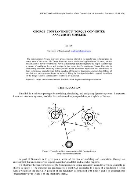
Figure 1. Typical graphical representation of G. Constantinescu<br />
torque converter mechanism<br />
A goal of Simulink is to give you a sense of the fun of modeling and simulation, through an<br />
environment that encourages you to pose a question, model it, and see what happens.<br />
To illustrate the basic principle of the Constantinescu torque converter, consider a typical example as<br />
shown in figure 1. The impulses are produced by a crank OA connected to a apex of a pendulum 3 (lever<br />
with a weight on the end C). A point B of the pendulum is connected with links 4 and 6 to unidirectional<br />
''mechanical valves" 5 and 7 on the secondary shaft 2.
83<br />
George Constantinescu’ Torque Converter analysis by Simulink<br />
Figure 2. The Simulink model of torque converter mechanism<br />
Figure 3. The Simulink model of unidirectional mechanism
Ion ION 84<br />
2. PHYSICAL MODEL BUILDING<br />
For torque converter analysis, in this paper are utilizing two kinds of block diagram modeling<br />
environment: SimMechanics for six bar mechanism OABDEF and SimDriveline for unidirectional<br />
mechanism and secondary shaft (see figures 2 and 3).<br />
SimMechanics and SimDriveline are parts of Simulink Physical Modeling, encompassing the<br />
modeling and design of systems according to basic physical principles. Physical Modeling runs within the<br />
Simulink environment and interfaces seamlessly with the rest of Simulink and with MATLAB. Unlike other<br />
Simulink blocks, which represent mathematical operations or operate on signals, Physical Modeling blocks<br />
represent physical components or relationships directly.<br />
SimMechanics is a block diagram modeling environment for the engineering design and simulation of<br />
rigid body machines and their motions, using the standard Newtonian dynamics of forces and torques.<br />
SimDriveline is a block diagram modeling environment for the engineering design and simulation of<br />
drivelines, or idealized powertrain systems. The function of a driveline is to propel a vehicle or craft by<br />
transferring its engine torque and power into vehicle momentum and kinetic energy. Drivelines consist of<br />
bodies spinning around fixed axes and subject to Newton's laws of motion.<br />
With SimMechanics, a researcher can model and simulate mechanical systems with a suite of tools to<br />
specify bodies and their mass properties, their possible motions, kinematic constraints, and coordinate<br />
systems, and to initiate and measure body motions.<br />
With SimDriveline, can be represent a driveline machine. He can initiate and maintain rotational<br />
motion in a driveline with actuators while measuring, via sensors, the motions of driveline elements and the<br />
torques acting on them.<br />
I represent a mechanical system by a connected block diagram, like other Simulink models, and I can<br />
incorporate hierarchical subsystems.<br />
SimMechanics analysis mode for studying this machine motion is forward (direct) dynamics. This<br />
mode computes the position and velocities of a system’s bodies at each time step, given the initial positions<br />
and velocities of its bodies and any forces applied to the system. SimMechanics integrates the accelerations<br />
twice to yield the velocities and positions as functions of time.<br />
ω<br />
ω<br />
ω<br />
2<br />
5<br />
7<br />
[ rev / min]<br />
time [] s<br />
Figure 4. Angular velocity diagrams: 1− ω5<br />
; 2 −ω7;<br />
3 − ω2<br />
.<br />
The dynamic model takes the form of a system of differential equation in time, with coefficients which<br />
are configuration dependent<br />
( )<br />
(1)<br />
2<br />
Mq+ Aq + Gq=<br />
r t<br />
where<br />
- M is the inertia matrix of the system,<br />
2<br />
- Aq<br />
represents centrifugal and Coriolis terms,<br />
- q generalized coordinates vector of the whole mechanism,
85<br />
George Constantinescu’ Torque Converter analysis by Simulink<br />
- G represents the action of gravity on the system,<br />
- r t represents the external torques (generalized forces) applied on the system.<br />
()<br />
2<br />
Following, the physical model shown in figure 2 is analyzed for initial dates: J = 0.<br />
kg ⋅ m ;<br />
1<br />
5<br />
2<br />
J<br />
2<br />
= 10kg<br />
⋅ m ; m3 = 5kg<br />
; OA = 10mm<br />
; AB = 100mm<br />
; AC = 500mm<br />
in two working condition<br />
actuation: 1 – prime mover with constant speed; 2 –prime mover with constant torque.<br />
[ Nm]<br />
M 2<br />
Figure 5. Output torque diagram ( )<br />
M 2 ω 2<br />
ω 2 [ rev / min]<br />
3. PRIME MOVER WITH CONSTANT SPEED ACTUATION MECHANISM<br />
For prime mover with constant angular velocity n<br />
1<br />
= 3000rev<br />
/ min (par example electromotor) and<br />
load torque M = 2<br />
0... 7000Nm , linear varying with respect to time ( t ) , the angular velocity diagrams for<br />
levers 5, 7 and unidirectional mechanism 2 are depicted in figure 4.<br />
The output torque diagram with respect to output angular speed ω is depicted in figure 5. The<br />
M 2<br />
2<br />
input torque diagram M1<br />
with respect with to output angular speed ω 2 is depicted in figure 6.<br />
[ Nm]<br />
M 1<br />
Figure 6. Input torque diagram ( )<br />
M 1 ω 2<br />
ω 2 [ rev / min]
Ion ION 86<br />
[ Nm]<br />
M 2<br />
[ ]<br />
Figure 7. Output torque diagram M 2 ( ω 2 )<br />
ω 2 rev / min<br />
ω 1<br />
[ rev / min]<br />
Figure 8. Intput angular velocity diagram ω 1( ω 2 )<br />
ω 2 [ rev / min]<br />
4. PRIME MOVER WITH CONSTANT <strong>TORQUE</strong> ACTUATION MECHANISM<br />
For prime mover with constant torque M<br />
1<br />
= 4000Nm<br />
actuation (par example internal-combustion<br />
engine), the output torque diagram and input angular velocity ω (with respect to output angular<br />
velocity ω 2 ) are drown in figures 7 and 8.<br />
M 2<br />
1<br />
5. CONCLUSIONS<br />
The inertia reaction loads applied from the pendulum 3 to the drive rods 4 and 5 as shown in figure 1,<br />
provides the variable transmission of power in the Constantinescu torque converter. The Constantinescu<br />
converter apply a ratcheting or one-way clutching device to convert an oscillating torque into a unidirectional<br />
torque. It utilize an inertial reaction force to achieve variable control. The output torque M 2 is the product of<br />
the input torque M 1 and the speed ratio. For the both case (prime mover with constant speed actuation<br />
constant or prime mover with constant torque actuation constant), it controls the magnitude of the output<br />
torque via the speed ratio.
87<br />
George Constantinescu’ Torque Converter analysis by Simulink<br />
This modeling of the dynamics for an automotive application is demonstrate its high performance<br />
characteristics. Analysis indicates that the upper design load limit is nearly unlimited (see figures 5 and 7) in<br />
high mechanical efficiency for most operational conditions, due to pure dynamic coupling and the small<br />
number of energy-dissipating components.<br />
REFERENCES<br />
1. BELL, E. T., An Irish Tragedy: Hamilton (1805-1865), Men of Mathematics, New York, Simon & Schuster, 1937.<br />
2. GOLDSTEIN, H., Classical Mechanics, Second Edition, Reading, Massachusetts, Addison-Wesley, 1980.<br />
3. MURRAY, R. M., Z. LI, and S. S. SASTRY, A Mathematical Introduction to Robotic Manipulation, Boca Raton, Florida, CRC<br />
Press, 1994.<br />
4. HARTENBERG, R. S., DENAVIT, J., Kinematic Synthesis of Linkages, Mc Graw Hill, 1964.<br />
5. *** Handbook of Industrial Robotics, edited by S. Y. Nof, John Wiley and Sons, 1985.<br />
6. HAUG, E., Computer Aided Kinematics and Dynamics of Mechanical Systems, volume I, basic methods, Allyn and Bacon,<br />
Boston, 1989.<br />
7. *** George CONSTANTINESCO Inertial Transmission, http://www.rexresearch.com/constran/1constran.html<br />
8. *** SimMechanics User’s Guide, http://www.mathworks.com<br />
9. *** SimDriveline User’s Guide, http://www.mathworks.com