KATSUHISA FURUTA, YAODONG PAN, YUKIHITO SUZUKU, Skil ...
KATSUHISA FURUTA, YAODONG PAN, YUKIHITO SUZUKU, Skil ...
KATSUHISA FURUTA, YAODONG PAN, YUKIHITO SUZUKU, Skil ...

Create successful ePaper yourself
Turn your PDF publications into a flip-book with our unique Google optimized e-Paper software.
<strong>Skil</strong>l Evaluation in Human Adaptive Mechatronics<br />
-- Bimanual Operation with XY-Stages--<br />
Katsuhisa Furuta * , Yaodong Pan † , Yukihito Suzuki ‡<br />
Abstract: In this paper, our HAM (Human Adaptive Mechatronics) research results on<br />
operator skill evaluation, operation assistance, identification of operator's dynamics,<br />
skill acquisition, and coupling phenomenon in bimanual operation are presented at<br />
first. Then the bimanual operation is discussed in detail. The phenomenon of spatial<br />
coupling between two different tasks performed by two hands respectively (bimanual<br />
operation) and the effect of frequency ratio and phase-lag between two circle tracking<br />
tasks on the bimanual operation are investigated in this paper. Two XY-stages<br />
developed in Tokyo Denki University are used as human-machine interfaces, with<br />
which various experiments on human bimanual cooperative operations have been<br />
conducted to investigate the human operation characteristics for the development of<br />
human adaptive mechatronic systems. In this paper, three bimanual operation<br />
experiments are presented, with which the phenomenon of spatial coupling was<br />
clearly observed. It was also found in experiments that a human operator can develop<br />
his/her skill of bimanual operation much easier with some frequency ratio and some<br />
phase-lag.<br />
Keywords: Spatial Coupling, <strong>Skil</strong>l Acquisition, Bimanual Operation, XY-stage,<br />
Haptic System, Operation Assisting, Human Adaptive Mechatronics.<br />
1. INTRODUCTION<br />
As a synergistic integration of electronics, mechanics, system sciences,<br />
control engineering, information technologies and other key technologies, the<br />
mechatronics has been improving the quality of human life. To use a mechatronic<br />
system effectively when a human operator is involved in the system, the operator<br />
should be skilled. Otherwise the mechatronic system should be able to assist the<br />
operator properly according to his skill level by providing necessary information,<br />
rules, and knowledge. In this way, an operator can learn and improve his/her skill<br />
and knowledge, and then can manipulate the system without any mis-operation<br />
even in complex and/or abnormal situations.<br />
Such mechatronic system which adapts to operator skill and assists to<br />
enhance it, is defined as Human Adaptive Mechatronics (HAM) [36][25][49]. It<br />
* President, Tokyo Denki University, 2-2 Kanda-Nishiki-cho, Chiyoda-ku Tokyo 101-8457 Japan<br />
† Control Systems Engineering, Honeywell, 3333 Unity Drive, Mississauga, ON L5L3S6, Canada<br />
‡ Department of Robotics and Mechatronics, Tokyo Denki University, 2-2 Kanda-Nishiki-cho,<br />
Chiyoda-ku Tokyo 101-8457 Japan<br />
Rev. Roum. Sci. Tech. − Méc. Appl., Tome 55, Nº _, P. , Bucarest, 2010
Katsuhisa Furuta, Yaodong Pan, and Yukihito Suzuki 2<br />
consists of Mechanism, Electronics, Computers, Systems and Control, and Human<br />
Sciences as depicted in Fig. 1.<br />
Human<br />
Control<br />
&<br />
Information<br />
Mechatronics<br />
Intelligent<br />
Mechanics<br />
&<br />
Electronics<br />
AI<br />
Cognitive<br />
&<br />
MedicalEng.<br />
Man-Machine<br />
Fig. 1 Diagram of Human Adaptive Mechatronics<br />
A HAM system should know the operator’s skill level so that proper<br />
assistances can be provided to the operator and then the operator can enhance his<br />
skill with the assistances. In Tokyo Denki University (TDU), we have designed<br />
HAM systems to identify the operator’s dynamical model [46][51], evaluate the<br />
operator’s skill level[42][50][47][45], provide assistances based on the operator’s<br />
skill level[42], and assist to enhance the operator’s skill[43]. In bimanual<br />
operations, the skill level can be evaluated by the coupling or decoupling<br />
information between two hands [50][47][45].<br />
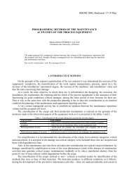
Fig. 2 Single XY-Stages<br />
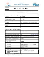
Fig. 3 Double XY-Stages
3<br />
<strong>Skil</strong>l Evaluation in Human Adaptive Mechatronics<br />
The phenomenon of coupling between tasks performed by two hands has<br />
been observed and studied since 1980s [14][12][15][4][33]. It has been found that<br />
there is a strong tendency for the movement of one hand to become more similar to<br />
the movement of another hand in any bimanual tasks, including different tasks for<br />
two hands and same tasks with different phase (Anti-phase or with phase-lag) for<br />
two hands [50][14]. The coupling affects the human operators’ operation skill<br />
and/or makes it difficult for the operator to improve his/her skill in bimanual<br />
operations. An XY-stage shown in Fig. 2 has been used in TDU for the research on<br />
HAM, with which we have developed HAM systems for assisting control,<br />
operation skill acquisition, and identification of operators’ dynamics.<br />
For the research on the bimanual operation, two XY-stages shown in Fig. 3<br />
have been designed in TDU [39], where each XY-stage is equipped with two DC<br />
motors, a six-dimension force sensor, and two encoders. A human operator can<br />
move the XY-stage through a grip equipped the force sensor. A PID controller is<br />
designed such that the XY-stages can follow the trajectory given by the human<br />
operator’s operation, including the position and force commands. The parameters<br />
of the PID controller were adjusted by measuring the response of the controlled<br />
XY-stage dynamics. As a human-machine interface, or an input device of a haptic<br />
system, the XY-stage provides an interface for the human operator such that the<br />
operator’s operation commands, including force, position, and velocity commands<br />
can be acquired and then be used as input signals to control a mechatronic system.<br />
In [28], a haptic control system that executes estimating of the human’s skill<br />
and assisting him was shown based on the concept of HAM. The estimation of the<br />
human’s operational characteristics is performed by identifying human’s dynamics<br />
with simple transfer function in real time. The assisting control is achieved by<br />
changing the ratio of an ideal machine operation and human’s operation. The<br />
strategy proposed in [35] consists of an identification of an operator’s control<br />
characteristics and an automatic tuning of dynamic property of the machine. The<br />
tuning is realized by changing impedance parameters of a virtual internal model<br />
(VIM) for the machine. An update law of the tuning is designed with a Lyapunov<br />
function. It was shown in [19] that in the control system design of the teleoperation<br />
based on VIM, slave systems with different dynamics can be controlled by the<br />
master-device with same dynamics.<br />
In this paper, some HAM research results in TDU about operator skill<br />
evaluation, operation assistance, identification of operator’s dynamics, skill<br />
acquisition, and coupling phenomenon in bimanual operation will be presented at<br />
first. Then the design procedure of XY-stages will be given. Three experiments of<br />
bimanual operation conducted with the XY-stages will be described. Three righthand<br />
health male students participating in this research were asked to operate two<br />
XY-stages to track reference trajectories on a line and a circle respectively in the<br />
first experiment, to track reference trajectories on two circles with two XY-stages<br />
respectively with different frequency ratio in the second experiment and with
Katsuhisa Furuta, Yaodong Pan, and Yukihito Suzuki 4<br />
different phase-lag in the third experiment. Based on the experimental results,<br />
some observation will be provided.<br />
The arrangement of the paper is as follows: Section 2 presents some HAM<br />
research results in TDU; Section 3 designs XY-stages; Section 4 describes the<br />
experiments conducted with XY-stages; Section 5 shows experimental results and<br />
gives observations; and Section 6 concludes the paper.<br />
2. RESEARCH RESULTS ON SKILL EVALUATION AND ASSISTING<br />
CONTROL<br />
1. Identification of Dynamic Characteristics in Human Operation [46]<br />
The mathematical model of the human operation [2] studied since long time<br />
ago includes various psycho-physical limitations inherent in the human operator.<br />
Kleinman and others [3] studied the dynamic characteristics of pilots as the control<br />
function point of view. McRuer [5] identified the operator dynamics as a linear<br />
combination of proportional and derivative with time delay. Miall et.al. considered<br />
that the human operator works as a Smith Predictor to compensate the time delay<br />
of the controlled object [13]. Furuta et. al. proposed that the skilled operator is<br />
constructing the reference model in a certain interval and his/her skill can<br />
compensate lacked information [32].<br />
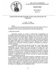
Fig.4 View Screen (Circular Motion)<br />
Fig.5 View Screen (Linear Motion)<br />
In this research, the operator dynamic characteristics are identified for<br />
developing an assisting control system with considering various conditions<br />
including time delay and partially signal missing. The XY-stage in Fig.2 is used as<br />
a man-machine interface in the data acquisition for the identification of human<br />
dynamics. An operator watches the display showing positions of the reference and<br />
the operator disks. The operator disk on the screen moves according to the XYstage<br />
position. When the reference disk moves circularly or horizontally as shown
5<br />
<strong>Skil</strong>l Evaluation in Human Adaptive Mechatronics<br />
in Fig.4 and Fig. 5, the operator manipulates the XY-stage to let the operator disk<br />
follow the reference disk.<br />
The XY-stage shown in Fig.2 is used for the human-machine interface,<br />
which is controlled to behave like a mass-damper dynamics with given parameters.<br />
The operator holds the grip and manipulates it during the experiment. The force<br />
applied to the grip is measured by the force sensor and the operator manipulates the<br />
XY-stage with the second order mass-damper dynamics. By choosing mass-damper<br />
parameters, the reaction feeling during the operation can be adjusted.<br />
The operator, the display and the XY-stage are shown in Fig. 6 and 7. The<br />
XY-stage is placed at three different positions; in front, 10cm right and 20cm right<br />
positions. The dynamic difference due to the relative position between the operator<br />
and the XY-stage is studied by indentifying the frequency response. The XY-stage<br />
is controlled by the internal model represented by three different mass-dumperspring<br />
parameters so that the effect to the different dynamics can be studied. Three<br />
different systems are used for the virtual internal model (VIM).<br />
Fig.6 Environment (Side View)<br />
Fig.7 Environment (Top View)<br />
Denote the gain by K and the transfer function of the human-machine<br />
interface by M ( jω ) , which is controlled to match to the mass-spring-damper<br />
model according to the VIM control method [11]. The operator is supposed to have<br />
a control structure similar to Kawato-Suzuki-Ito model shown in Fig. 8 with a<br />
feedforward transfer function H () s 1<br />
and a feedback one H () s 2<br />
.<br />
Fig.8 Block Diagram of Kawato Suzuki Model
Katsuhisa Furuta, Yaodong Pan, and Yukihito Suzuki 6<br />
The frequency characteristics of the total operator and machine combined<br />
system G(<br />
j ω ) is determined by<br />
( H1( jω) + H2( jω)) M( jω)<br />
K<br />
G( jω)<br />
= .<br />
1 + H ( jω) M( jω)<br />
K<br />
2<br />
It is assumed that the operator dynamics H ( jω ) including the feedback is<br />
represented as<br />
The total transfer function G(<br />
j )<br />
H ( jω) + H ( jω)<br />
Hc<br />
( jω)<br />
1 + H2( jω) M( jω)<br />
K<br />
ω can be re-written as<br />
G( jω) = H ( jω) M( jω)<br />
K.<br />
1 2<br />
= .<br />
The frequency characteristics Hc(<br />
j ω ) is considered as the operator<br />
frequency characteristics. The identification of the operator frequency<br />
characteristics gives G(<br />
j ω ), from which Hc<br />
( j ω ) can be determined since the<br />
dynamics of human-machine interface is known. It is shown by identification<br />
results that G( jω ) is equal to 1 over a certain frequency band. Thus Hc<br />
( ω ) gives<br />
the inverse characteristics of the machine, which is said usually the human<br />
dynamic characteristics. It is also found from identified results that a human<br />
operator adapts to the variation of the human-machine dynamics so that the<br />
dynamics of the total system does not change as far as the operator can afford to<br />
adapt to the change of the controlled system dynamics.<br />
The identified transfer functions H 1<br />
( j ω ) and H ( j ) 2<br />
ω of the human<br />
operator are shown in Figs. 9 and 10 for unskilled and skilled operators,<br />
respectively.<br />
c<br />
c
7<br />
<strong>Skil</strong>l Evaluation in Human Adaptive Mechatronics<br />
Fig.9 Bode Plot of unskilled operator<br />
Fig.10 Bode Plot of skilled operator<br />
2. Assisting Control in Human Adaptive Mechatronics – Single Ball Juggling – [42]<br />
In [3], it is considered that the reference for the operation is given. During<br />
the operation, however, the operator should generate the desired trajectory from the<br />
available information. The human operation is successful if the proper reference is<br />
generated and is tracked by the controlled variable. To enhance the operation skill,<br />
a human operator learns through the practice assisted by a teacher who corrects the
Katsuhisa Furuta, Yaodong Pan, and Yukihito Suzuki 8<br />
operation by the additional force if the operator’s manipulation is not appropriate.<br />
Such assistance in the learning stage is found in many places such as driving<br />
vehicles and others.<br />
An example of operations requiring the skill may be the juggling of the<br />
multiple objects, where the operator watches movements of objects and<br />
synchronizes the manipulation by hands. In [42], a single ball juggling system has<br />
been developed, which swings up repeatedly a golf ball. The ball connected by a<br />
string to a fixed place is hit by a slider at the bottom of swing as shown in Fig. 11.<br />
The string connected to the ball can be considered as a pendulum [25]. Fig. 13<br />
shows the structure of the developed assisting system for the operator.<br />
Fig.11 Model of Juggling System<br />
Fig.12 Screen Image for Juggling<br />
.<br />
Fig.13 Juggling Assisting Control system<br />
The position of the slider is controlled by the X-Y stage (shown in Fig.2)<br />
manipulated by an operator. The operator looks at a screen where the position of
9<br />
<strong>Skil</strong>l Evaluation in Human Adaptive Mechatronics<br />
the ball, the reference position of the slider and the actual position of the slider are<br />
displayed as shown in Fig.12.<br />
The block diagram of the control system is schematically shown in Fig. 14,<br />
where the sampler switch in the closed state denotes the impact of the slider against<br />
the ball.<br />
Fig.14 Block Diagram of Control<br />
The assisting control system is designed so that the system works smoothly<br />
in the presence of the false operation which may be considered as the disturbance<br />
to the control system. To design the assisting control system, the reference motion<br />
of the slider should be determined [26][27]. The slider moves according to the<br />
command of the X-Y stage manipulated by the operator. The assisting control<br />
system includes Kawato-Suzuki Type model for the voluntary motion of muscle<br />
[8][9] as shown in Fig. 14, where the off-set to the compensator may indicate the<br />
skill level and by measuring this error the operator skill level may be evaluated.<br />
The X-Y stage used as a human-machine interface is controlled to have the<br />
mass-damper dynamics with given parameters. The operator holds the grip and<br />
manipulates it in the experiment. The force applied to the grip is measured by the<br />
force sensor. The operator manipulates the XY stage, whose dynamic relation<br />
between the position and the applied force is controlled to satisfy the second order<br />
mass-damper system VIM. By choosing the parameters of mass-damper, the<br />
feeling in the operation can be adjusted. Then the controller for the corrective force<br />
of the teacher’s role is designed so that the virtual position in VIM tracks the given<br />
reference of the slider. The slider is controlled to follow the position of X-Y stage.
Katsuhisa Furuta, Yaodong Pan, and Yukihito Suzuki 10<br />
Fig.15 Ball’s Position and Reference Height<br />
In the designed assisting control system for this juggling operation, the<br />
operator and the assisting forces are additionally applied to the grip of the X-Y<br />
stage. Either the assisting control system or an operator can alone juggle the ball.<br />
The total assisting system consists of two parts; one is the reference generation<br />
from the ball motion and another is to control the X-Y stage to assist the operator.<br />
Letting the transfer function of the human-machine interface be controlled to<br />
match the VIM, the transfer function of the teaching part can be designed properly<br />
for VIM. By the proper choice of the limiters for the applied forces by the assisting<br />
system and the operator, the operator can be properly assisted.<br />
With the designed system, the juggling operation is tried by changing the<br />
reference ball height. One of experimental results is shown in Fig. 15.<br />
3. Control System for <strong>Skil</strong>l Acquisition – Balancing Pendulum based on Human<br />
Adaptive Mechatronics- –[43]<br />
An assistance system with force feedback for skill acquisition has been<br />
developed in TDU [43]. In this system, the operation task is to balance an inverted<br />
pendulum on a cart. For this purpose, a virtual pendulum that is calculated realtime<br />
with computer graphics is developed. A human operator manipulates an XYstage<br />
as the human-machine interface with haptic function to balance the<br />
pendulum. An assistant controller is designed based on the Kawato-Suzuki model<br />
shown in Fig.16 [8][9]. In this model, it is proposed that the progress of the skill<br />
may bring the increase of feedforward and reduction of feedback actions.
11<br />
<strong>Skil</strong>l Evaluation in Human Adaptive Mechatronics<br />
Fig.16 Architecture of teaching based on Kawato-Suzuki model<br />
Fig.17 Model of the Inverted Pendulum on the Cart<br />
A “student operator” directly operates the plant in the feedforward way and<br />
the teacher corrects the operation by the correcting force based on the error<br />
between the reference and the output. When the error vanishes, the student can<br />
operate desirably, which means that he/she can develop the inverse model of the<br />
plant by himself/herself. Thus the student can learn how to use appropriate force<br />
for the operation by the teacher’s assistance. When the inverse model is completely<br />
developed, it is no need to implement the teacher’s force.<br />
The pendulum and the cart are schematically shown in Fig.17. The position<br />
of the cart is controlled by the command from the man-machine interface<br />
manipulated by the operator, where the XY-stage shown in Fig.2 is used as the<br />
human-machine interface.<br />
The operator gets the information of the angle of the pendulum and the<br />
position of the cart through the screen as shown in Fig.18. The scene of the<br />
experiment system is shown in Fig.19. The block diagram of the control system is<br />
schematically shown in Fig.20, which is based on VIM to make the bilateral<br />
control system [11].
Katsuhisa Furuta, Yaodong Pan, and Yukihito Suzuki 12<br />
Fig.18 Information on the Screen<br />
Fig.19 Scene of Environment<br />
Fig.20 Block Diagram of Control<br />
The forces from the operator and the controller are additionally applied to<br />
the grip of the XY-stage. By the help of assistance control system the operator can<br />
balance the pendulum even when he/she has not the skill. By the proper choice of<br />
the upper and lower bounds of the applied force for the assisting system and the<br />
operator, the operator can be properly assisted. To design the assisting control<br />
system, a reference is determined at first. In the system, there are three controllers,<br />
i.e., the assistance controller, the VIM following controller for the XY-stage and<br />
the VIM following controller for the cart. Experiments with and without assisting<br />
force were performed. The results show that the virtual inverted pendulum can be<br />
well-stabilized by a human operation and the assist control when the operator was<br />
trained through the testing with the assisting force. It was confirmed in the<br />
experiments that the human operator had acquired the skill after training with the<br />
proposed assist method.<br />
4. Capsubot [44]<br />
As one of HAM research results in TDU, a capsule type robot named<br />
capsubot, shown in Fig.21 has been developed. The robot has no moving part<br />
outside its body, no legs, and no wheel. Its motion is purely based on its internal<br />
force and friction with the environments.
13<br />
<strong>Skil</strong>l Evaluation in Human Adaptive Mechatronics<br />
Fig.21 Capusbot developed in TDU<br />
The capsubot is a two mass system. It consists of a capsule shell<br />
cylinder mass<br />
m 2<br />
and a<br />
. The internal force between the shell and the cylinder is<br />
generated using permanent magnet and coil pair, which makes the cylinder mass<br />
move forward and backward inside the capsule shell.<br />
To move the capsubot forward, a four step motion pattern [44] has been<br />
proposed as follows:<br />
I. Large backward accelerated motion of m<br />
2<br />
, forward accelerated motion of m<br />
1<br />
.<br />
II. Small backward decelerated motion of m<br />
2<br />
, forward decelerated motion of m<br />
1<br />
.<br />
III. Small backward decelerated motion of m<br />
2<br />
, m<br />
1<br />
remains stationary.<br />
IV. Forward slow motion of m<br />
2<br />
, m<br />
1<br />
remains stationary.<br />
Since the capsule robot has no external moving parts and can be made small<br />
in size, it has a large applicability in medical field, for example, as a self-propelled<br />
endoscope.<br />
5. Coupling Phenomenon Observed with NIRS in Bimanual Operation [50]<br />
The phenomenon of coupling between tasks performed by two hands<br />
respectively has been observed and studied since 1980s [14][12][15][4]<br />
[24][30][21]. It has been found that there is a strong tendency for the movement of<br />
one hand to become more similar to the movement of another hand in bimanual<br />
tasks, including different tasks for two hands and same tasks with different phase<br />
(Anti-phase or with phase delay) for two hands [14]. In this research, a NIRS,<br />
EGT-4000 Optical Topography System made by Hitachi Medical Corporation,<br />
Japan is used to measure the activation of the motor cortex in healthy subjects<br />
during bimanual and unimanual finger-tapping tasks.<br />
It is said that only left or right side of the motor cortex area is active when a<br />
subject’s contralateral hand (or fingers of the contralateral hand or the contralateral<br />
arm) is moving in a slow or normal speed. Thus in those tests with unimanual<br />
tasks, in general, only one side of the motor cortex area was paid attention [22]. In<br />
this research, both sides of the motor cortex area will be observed in unimanual<br />
operation to find the reason of the coupling between the left and right of the motor<br />
cortex areas for the bimanual operation especially when the subjects were asked to<br />
perform the bimanual and unimanual finger-tapping tasks as quick as possible. The<br />
relation between the coupling and the subjects’ skill is also investigated.<br />
m 1
Katsuhisa Furuta, Yaodong Pan, and Yukihito Suzuki 14<br />
In the experiments, subjects were asked to perform finger-tapping tasks in<br />
different patterns with two or all fingers of his left or right or both hands with<br />
visual instructions or with oral instructions.<br />
As a typical result, Fig.22 shows the concentration change of [HHb] while a<br />
subject was performing finger-tapping tasks with his left hand, right hand, and both<br />
hands, respectively. In the figure, the red area indicates the high concentration in<br />
this area.<br />
Figure 22 Change of [HHb] during Two-Fingers Tapping with Visual Instruction<br />
It is clear from Fig.22 that only right motor cortex is active for the left<br />
finger-tapping and only left motor cortex is active for the right finger-tapping in the<br />
low speed operation with the tapping period less than 0.4 second (Left Hand<br />
Operation) or 0.7 second (Right Hand Operation), and both sides of the motor<br />
cortex area become more active for quicker operation speed with the tapping<br />
frequency larger than 0.5 second (Left Hand Operation) or 0.6 second (Right Hand<br />
Operation). For a right-handed subject, much more activation in both sides of the<br />
motor cortex area can be observed in the finger tapping of left hand, and the<br />
operation speed for both sides of the motor cortex area to become active is slower<br />
in the finger-tapping of left hand than the finger-tapping of right hand.<br />
Fig.23 shows the concentration change of [HHb] when another subject was<br />
alternatively pushing two switches down with his index and middle fingers of both<br />
hands in anti-phase.
15<br />
<strong>Skil</strong>l Evaluation in Human Adaptive Mechatronics<br />
Fig.23 Relation between <strong>Skil</strong>l and Change of [HHb] in Bimanual Operation<br />
In the first and second trials, the strong activation in this subject’s motor<br />
cortex area can be observed even with low operation speed. In the third and forth<br />
trials, the activation became weaker and weaker while the skill of the subject was<br />
enhanced more and more. The threshold speed with which the motor cortex area in<br />
bimanual operation becomes much more active increases with the development of<br />
the operation skill.<br />
It is found in this research that not only contralateral side of the motor cortex<br />
area is active when a subject’s right/left hand (or fingers of right/left hand or<br />
right/left arm) is moving in a high speed, but also the ipsilateral side of the motor<br />
cortex area. This reveals that the coupling between left and right motor cortex areas<br />
is the reason why the bimanual operation effects with each other. A higher move<br />
speed in bimanual operation results in more active in both side of the motor cortex<br />
area. And the threshold speed with which the motor cortex area in bimanual<br />
operation becomes much more active depends on the operation skill of the subject.<br />
Less coupling phenomenon in the right-handed subjects’ right hand operation than<br />
the left hand operation is observed, which also explains the relation between the<br />
coupling and the operation skill because for right-handed subjects, they can control<br />
their right hands much better than their left hands. The coupling phenomenon<br />
found in this research should be taken into consideration in the design of bimanual<br />
operation mechatronic system.
Katsuhisa Furuta, Yaodong Pan, and Yukihito Suzuki 16<br />
6. Decoupling and <strong>Skil</strong>l Development in Bimanual Operations [47]<br />
It has been observed in our bimanual experiments with two XY-stages that<br />
one hand motion affects another hand motion in bimanual tasks with high<br />
frequency, and the effect becomes weaker in lower frequency and for skilled<br />
operators [39]. Researches to analyze human bimanual motion have been done in<br />
the field of ergonomics [16]. Some researchers have analyzed human dynamics<br />
from the control engineering point of view [28][19].<br />
In complex systems with several controlled variables, like robot manipulator<br />
or aircraft control, inputs are strongly coupled with outputs of the system. A<br />
decoupled control algorithm is often used so that each output or each degree of<br />
freedom of the complex system can be controlled separately [34]. In this research,<br />
this phenomenon is analyzed from the viewpoint of decoupling control.<br />
In this research, two XY-stages shown in Fig.3 are used to construct a<br />
bimanual operation system. An operator manipulates two XY-stages<br />
simultaneously by using both hands, to trace two periodic reference trajectories.<br />
The reference trajectories are displayed on the screen as inputs to human operator.<br />
The operator’s hand positions are considered as outputs, and the transfer function<br />
of the human operator is identified from experimental data. The displayed<br />
reference signals on the plane are considered as the complex variables. This makes<br />
the identification require less computation. The experimental set-up for the<br />
bimanual operation is shown in Fig. 24.<br />
Fig.24 System Configuration<br />
The reference and actual positions of XY-stages are given to the operator as<br />
visual information on the projected display. The operator simultaneously<br />
manipulates two XY-stages to follow reference points moving in different<br />
directions. The positions of XY-stages are shown by “× " on the screen. A human<br />
frequency response is identified from the reference and the XY-stage trajectories.<br />
For the bimanual operation analysis, we consider both inputs ( , u ) and<br />
outputs (<br />
y<br />
1<br />
, y<br />
2<br />
) ( ui<br />
,<br />
y<br />
i<br />
u1<br />
2<br />
2<br />
∈ R , i = 12) , as the complex variables in C . The x -
17<br />
<strong>Skil</strong>l Evaluation in Human Adaptive Mechatronics<br />
axis components correspond to its real part and y -axis components correspond to<br />
its imaginary part. The reference inputs are<br />
⎡u1()(4) t ⎤ ⎡ jr sin ωt(6)<br />
⎤<br />
ut () = ⎢<br />
u2()(5) t<br />
⎥ = ⎢<br />
rcos ωt(7)<br />
⎥<br />
⎣ ⎦ ⎣ ⎦<br />
where u () t is the reference position of right hand, u () t<br />
1 2<br />
is the reference position<br />
of left hand. Let the right hand position be<br />
y , and<br />
y<br />
1<br />
and left hand position be 2<br />
they are the complex variables similar to the inputs. Thus, the actual positions of<br />
each operator’s hands can be expressed as<br />
⎡ y ()(9 t ) ⎤<br />
1<br />
= ⎢<br />
y2(<br />
t)(10)<br />
⎥<br />
yt ()<br />
⎣ ⎦ .<br />
The relation between the input and the output vectors is<br />
Y( jω) = H( jω)U( jω)<br />
⎡H11( jω) H ( jω)(13)<br />
H( jω)<br />
12 ⎤<br />
= ⎢<br />
H21( jω) H22( jω)<br />
⎥<br />
⎣<br />
⎦<br />
where U ( jω) and Y ( j ω)<br />
are the Fourier Transforms of the input u and output<br />
y , respectively. H( jω ) is the frequency transfer function between both inputs<br />
and two hand outputs.<br />
From experimental data, the transfer functions are identified as shown in<br />
Fig.25.<br />
(a) Left-hand reference to left-hand response H ( jω ) 11<br />
(b) Right-hand reference to right-hand response H ( jω ) 22
Katsuhisa Furuta, Yaodong Pan, and Yukihito Suzuki 18<br />
(c) Left-hand reference to right-hand response H ( jω ) 21<br />
(d) Right-hand reference to left-hand response H ( jω ) 12<br />
Fig.25 Frequency Characteristics of Bimanual Operation<br />
It is clear from Fig. 25(a) and (b) that the phase lags become smaller in the<br />
fourth trial compared with the first trial. This means that the operator’s skill in this<br />
tracking task is improved by training. The transfer function gains | H ( jω)<br />
| and<br />
11<br />
| H ( jω)<br />
22<br />
| are almost zero [dB] and unchanged through the training. One possible<br />
reason is that the human operator can predict the required distance of the arm<br />
movement. As for the coupling motion, the phase curves of H 12<br />
( jω ) and<br />
H ( ) 21<br />
jω imply the existence of time delay. Thus we know that the hand coupling<br />
motion has a characteristic of time delay.<br />
To evaluate the skill based on the frequency response identification results, a<br />
criterion function is defined to quantify the operator’s skill. For an expert operator,<br />
the criterion function is zero. Table 1 shows the criterion function values in the first<br />
and the forth trials. Thus using the criterion function, we can measure the level of<br />
operator’s skill.<br />
Table 1 Evaluated Criterion Function Values<br />
Subject A Subject B Subject C Subject D<br />
1st Trial 0.0059 1.0788 0.0200 0.0117<br />
4th Trial 0.0026 0.4444 0.0044 0.0070
19<br />
<strong>Skil</strong>l Evaluation in Human Adaptive Mechatronics<br />
3. XY-Stages<br />
Based on the operation conditions, such as the moving range, speed, and<br />
frequency for a normal operator, two XY-stages were designed with the size being<br />
60 cm in both X and Y axes and with two DC motors, which can drive the stages<br />
with necessary torque and necessary speed [39].<br />
1. Motors and Encoders<br />
As the arm moving along Y axis is mounted on the arm moving along X<br />
axis, the motor to drive the XY-stage along X axis is more powerful than the one<br />
used in Y axis. The DC motors used in X and Y axes are SGDS-08A01A and<br />
SGDS-04A01A of Yaskawa Electric Cooperation products, respectively. They can<br />
provide up to 19 . 3 N-m and 10. 3 N-m output torque for X and Y axes, respective<br />
with 750 W and 400 W. Both encoders for X and Y axes are with 2048 P/Rev<br />
resolution.<br />
(a) X Axis (b) Y Axis (c) Force Sensor with Grip<br />
Fig.26 Motors, Encoders and Force Sensor used in XY-Stages<br />
2. Force Sensor<br />
A grip is mounted on a 6-dimension force sensor (Nitta, IFS-70M35A25-M50B). The<br />
nominal force ranges are 100 N along X and Y directions and 200 N along Z direction.<br />
The nominal moment ranges are 10 Nm about all three axes. The resolutions are 0.<br />
01N<br />
in X and Y and 00 . 2 N in Z while they are 1 Nmm in all three moments.<br />
3. XY‐Stage Control System<br />
The XY-stages are controlled by a PID compensator based on the Virtual<br />
Internal Model control method [11]. The control block diagram is shown in Fig. 27.<br />
And the parameters of XY-stage are shown in Table 2.
Katsuhisa Furuta, Yaodong Pan, and Yukihito Suzuki 20<br />
Fig.27 Controller of XY-Stage<br />
Table 2 Parameters of XY-stage<br />
F [ ] h<br />
N<br />
Force by operator<br />
F [ ] c<br />
N<br />
Control input<br />
M [ ] md<br />
kg Mass of VIM<br />
D [ ]<br />
md<br />
Ns/ m<br />
Viscosity of VIM<br />
X [ ] md<br />
m Position of VIM<br />
X<br />
Position of XY-stage<br />
p<br />
M [ ] p<br />
kg Mass of XY-stage<br />
D [ ]<br />
p<br />
Ns/ m Viscosity of XY-stage<br />
e<br />
m<br />
Error<br />
md p<br />
The model of the XY-stage can be written as<br />
M X + D X = F + F .<br />
X<br />
p p p p h c<br />
− X<br />
Therefore the virtual internal mode of the XY-stage used in the controller is<br />
determined by<br />
M<br />
mXm + DmXm = Fh<br />
with parameters being<br />
M<br />
p<br />
= 26[kg], D<br />
p<br />
= 22[Ns/m], M<br />
m<br />
= 7[kg], D<br />
m<br />
= 10[Ns/m].<br />
The PID compensator is in the form of<br />
F<br />
c<br />
= M − 1 m<br />
( M p(<br />
− D X F )<br />
m m<br />
+<br />
h<br />
+ DX<br />
p p<br />
−Fh − FEM<br />
p<br />
⎡<br />
⎤<br />
where F = ⎢KI KP KD<br />
⎥,<br />
⎣<br />
⎦<br />
∫<br />
⎡ ⎤<br />
⎢<br />
emxdt<br />
⎥<br />
K<br />
E = ⎢ e ⎥<br />
mx<br />
., and K<br />
⎢ ⎥<br />
⎢ e<br />
mx ⎥ K<br />
⎣ ⎦<br />
P<br />
I<br />
D<br />
= 0.<br />
000006<br />
= 21232.<br />
0 .<br />
= 65. 135.
21<br />
<strong>Skil</strong>l Evaluation in Human Adaptive Mechatronics<br />
4. Experiment Setups<br />
Three right-handed healthy male students as the subject with their age<br />
ranging from 21 to 27 participated in this research. None of them has special life<br />
background which may result in a high motor skill such as player of piano or violin<br />
or sportsman. They were asked to stand in the front of XY-stages in their most<br />
comfortable posture, look at the screen of a project connected to the PC which<br />
gives the reference trajectories for left and right hands and shows the real trajectory<br />
of the XY-stages, move two XY-stages with his left and right hands respectively as<br />
shown in Figs.28 and 39 to track two reference trajectories given in the screen.<br />
Fig.28 Experimental Scene 1 Fig.29 Experimental Scene 2<br />
The trajectories to be tracked are rhythmic signals either alone a straight line<br />
or alone a circle. The frequency and the phase of each reference trajectory may be<br />
adjusted according to the experimental requirements.<br />
1. Experiment 1<br />
In this experiment, the spatial coupling is investigated when the subjects are<br />
asked to move the XY-stages to track two trajectories running on a straight line and<br />
a circle, respectively. The experimental environment is shown in Fig.30.<br />
On the right side of the screen used to give the target commands to the<br />
human operator, there are a circle, a point on the circle, and a symbol “x”. The<br />
point moves on the circle with a fixed radius in a certain speed. The symbol “x”<br />
shows the current position of the left XY-stage. On the left side of the screen, there<br />
are a straight line, a point on the line, and a symbol “x”. The point moves on the<br />
line with a certain speed. The symbol “x” shows the current position of the right<br />
XY-stage. The operators are asked to hand the grips mounted on the force sensors<br />
and to move the XY-stages through the grips so that the positions of the XY-stages<br />
track the points running on the line and the circle, respectively. The forces from the<br />
operators’ hands and the positions of the XY-stages are recorded for the analysis of<br />
the experimental results. The moving speeds of the point on the line and the circle<br />
are changed with the frequency being ω = 03 . , 04 . , 05 . , 07 . , 10 . Hz. The
2<br />
0<br />
[<br />
m<br />
]<br />
Katsuhisa Furuta, Yaodong Pan, and Yukihito Suzuki 22<br />
trajectories of reference points denoted as ( xleft<br />
() t , yleft<br />
() t ) and ( xright<br />
() t ,<br />
yright<br />
() t ) are determined by<br />
xleft<br />
() t = 0<br />
rπ<br />
t<br />
yleft<br />
() t = s ( ( ))<br />
2ω<br />
∫ ign cos ωt dt<br />
o<br />
xright<br />
() t = rcos( ωt)<br />
yright<br />
() t = rsin( ωt)<br />
where<br />
r = 005 . m<br />
ω changes with<br />
ω = 030405 ., ., ., 0710Hz .,.<br />
and the frequency ratio f takes values among<br />
f = 1/ 1, 2/ 1, 4/ 3,5/ 3, 6/ 5.<br />
2. Experiment 2<br />
In this experiment, the effect of the frequency ratio on the operators’<br />
operation skill is investigated when the subjects are asked to move the XY-stages<br />
to track two trajectories moving on circles, respectively. The experimental<br />
environment is shown in Fig. 31.<br />
c<br />
Fig.30 Environment of Experiment 1 Fig.31 Environment of Experiments 2&3<br />
On the screen, there are two circles, a point on each circle, and two symbol<br />
“x”’s. The points move on the circles with a fixed radius in a certain speed. The<br />
symbol “x”’s shows the current positions of the left and right XY-stages. The<br />
moving speed of the point on the left circle are changed with the frequency being<br />
ω = 03 . , 04 . , 05 . , 07 . , 1.<br />
0 Hz and the frequency ratio between two trajectories
23<br />
<strong>Skil</strong>l Evaluation in Human Adaptive Mechatronics<br />
are set to be 1 :1, 1 : 2, 3 : 4, 3: 5, and 5 : 6. The trajectories of reference points<br />
denoted as ( xleft<br />
( t ), yleft<br />
() t ) and ( xright<br />
() t , yright<br />
() t ) are determined by<br />
xleft<br />
() t = rcos( ωt)<br />
yleft<br />
() t = rsin(<br />
ωt)<br />
xright<br />
() t = rcos( fωt)<br />
yright<br />
() t = rsin(<br />
f ωt)<br />
where<br />
r = 005 . m<br />
ω changes with<br />
ω = 0304050710Hz<br />
., ., ., .,.<br />
and the frequency ratio f takes values among<br />
f = 1/<br />
1, 2/<br />
1, 3/ 4, 3/ 5,<br />
5/ 6.<br />
3. Experiment 3<br />
In this experiment, the experimental setup is similar to the one in Experiment<br />
2 except that the frequency ratio is fixed to be 1 :1 but the phase-lag between two<br />
trajectories for the left and the right hands are considered to be 0 Degree, 45<br />
Degree, 75 Degree, 90 Degree, 125 Degree, and 180 Degree. The trajectories of<br />
reference points denoted as ( xleft<br />
() t , yleft<br />
() t ) and ( xright<br />
() t , yright<br />
() t ) are<br />
determined by<br />
xleft<br />
() t = rcos( ωt)<br />
yleft<br />
() t = rsin( ωt)<br />
xright<br />
() t = rcos( ωt+<br />
θ )<br />
yright<br />
() t = rsin( ωt<br />
+ θ )<br />
where<br />
r = 005 . m<br />
ω changes with<br />
ω = 0304 ., ., 050710Hz ., .,. ,<br />
and the phase-lag θ takes values among<br />
θ = 0, 45, 75, 90, 125, 180Deg..
Katsuhisa Furuta, Yaodong Pan, and Yukihito Suzuki 24<br />
5. Experimental Results and Discusses<br />
1. Spatial Coupling<br />
As the results of Experiment 1, Fig.32 shows the spatial coupling existing in<br />
bimanual operation when two trajectories on a straight line and on a circle are<br />
tracked by two XY-stages, respectively. And the coupling becomes stronger for a<br />
higher moving speed of XY-stages.<br />
Fig.32 Line and Circle Tracking Result (Red Line: Reference Trajectory, Black: 0.2<br />
Hz, Yellow: 0.3Hz, Blue: 0.7Hz)<br />
2. Effect of Frequency Ratio<br />
Figure 33 shows the tracking error for each frequency ratio in Experiment 2.<br />
It is clear that the trajectories on circles are much more difficult to track and thus<br />
are with much larger tracking error when the number in nominator and/or<br />
denominator is larger.<br />
Figure 33 Circle Tracking Error with Different Frequency Ratio (Black: 1:1, Yellow:<br />
1:2, Green: 3:4, Brown: 3:5, Blue: 5:6)
25<br />
<strong>Skil</strong>l Evaluation in Human Adaptive Mechatronics<br />
Figs. 34 and 35 show the development of the human operator’s operation skill where the<br />
tracking performance is improved after the operator repeated his operation several times. It<br />
is found that the skill is quit improved for low speed operation and is not improved for<br />
higher speed operation when the frequency ratio is with larger numbers in its nominator<br />
and/or denominator. When the XY-stages are operated in the same frequency and the same<br />
phase, the operation skill is improved in both low and high speed operation.<br />
(1st Try)<br />
(2nt Try)<br />
(3rd Try)<br />
(4th Try)<br />
Fig.34 <strong>Skil</strong>l Development in Circle Tracking (Frequency Ratio: 1:1)<br />
(1st Try)<br />
(2nt Try)<br />
(3rd Try)<br />
(4th Try)
Katsuhisa Furuta, Yaodong Pan, and Yukihito Suzuki 26<br />
Fig.35 <strong>Skil</strong>l Development in Circle Tracking (3:4)<br />
3. Effect of Phase-lag<br />
The effect of the phase-lag was observed in Experiment 3 as shown in<br />
Fig.36. It is found in the experiment that the skill is difficult to be improved when<br />
there exists phase-lag between two XY-stages’ operations.<br />
(0 Deg.) (45 Deg.)<br />
(75 Deg.) (90 Deg.)<br />
(125 Deg.) (180 Deg.)
27<br />
<strong>Skil</strong>l Evaluation in Human Adaptive Mechatronics<br />
Figure 36 Circle Tracking Error with Phase-lag<br />
6. CONCLUSION<br />
In this paper, some HAM research results in TDU about operator skill evaluation, operation<br />
assistance, identification of operator’s dynamics, skill acquisition, and coupling<br />
phenomenon in bimanual operation were presented. Then two XY-stages were designed.<br />
The experimental results to investigate the phenomenon of spatial coupling, the effect of<br />
frequency ratio and phase-lag with the XY-stages were given. It was found that the<br />
bimanual operation is much more difficult and the procedure to improve the operation skill<br />
is slower when the frequency ratio is with larger numbers in its nominator and/or<br />
denominator and/or there exists phase-lag except of anti-phase.<br />
7. ACKNOWLEDGMENTS<br />
This research is supported by the Grant-in-Aid for 21st Century COE (Center of<br />
Excellence) Program in Ministry of Education, Culture, Sports, Science and Technology,<br />
Japan. The authors are grateful to the Ministry for supporting this work and would like to<br />
thank all members of the HAM research group in Tokyo Denki University for the<br />
collaborative research.<br />
References<br />
[1] R. W. Wilde, J. H. Westcott, “ The characteristics of the human operator engaged in a<br />
trackin task", Automatica, Vol. 1, 5-19, 1962.<br />
[2] Brian Gaines, “Linear and Nonlinear Models of teh Human Controller”, Int. J. of Man-<br />
Machine Studies,pp.353-560,1969<br />
[3] D.L. Kleinman, S. Baron and W.H. Levinson, “An Optimal Control Model of Human<br />
Response—Part I: Theory and Validation”, Automatica, Vol. 6, pp. 357–369, 1970.<br />
[4] Yamanishi, J., Kawato, M., Suzuki, R., 1980. Two coupled oscillators as a model for<br />
the coordinated finger tapping by both hands. Biol. Cybern. 37, 219–225.<br />
[5] D.McRuer,"Human Dynamics in Man-Machine Systems",Automatica, Vol. 16, pp. 237-<br />
253, 1980<br />
[6] D. Mcruer, “ Human dynamics in man-machine systems", Automatica, Vol. 16, 237-<br />
253, 1980.<br />
[7] Larry Hirschhorn, Beyond Mechanization, Cambridge, MA: MIT Press, 1984
Katsuhisa Furuta, Yaodong Pan, and Yukihito Suzuki 28<br />
[8] M. Kawato, “Adaptation and learning in control of voluntary movement”, J. Robot Soc.<br />
Jpn., Vol. 4, No. 2, pp. 110-119, 1986.<br />
[9] Y. Uno, M. Kawato, and R. Suzuki, “Formation and control of optimal trajectory in<br />
human multijoint arm movement”, Biol. Cybern., Vol. 61, pp. 89-101, 1986.<br />
[10] D.T. Delpy, M. Cope, P. van der Zee, S. Arridge, S. Wray and J. Wyatt, “Estimation of<br />
Optical Pathlength through Tissue from Direct Time of Flight Measurement”, Physics in<br />
Medicine and Biology, vol.33, No.12, pp.1433–1442, 1988<br />
[11] K. Kosuge, K. Furuta, Y. Shiote, H. Hatano. ”Control of Master-Slave Manipulator<br />
Based on Virtual Internal Model", Journal of Robotics and Mechatronics, Vol.2, No.5,<br />
pages.358-363, 1989.<br />
[12] Franz, E.A., Zelaznik, H.N., McCabe, G., 1991. Spatial topological constraints in a<br />
bimanual task. Acta Psychol. 77, 137–151.<br />
[13] R.C. Miall, D.J. Weir, D.M. Wolpert, J.F.Stein,“Is the Cerebellum a Smith Predictor?",<br />
Journal of Motor Behavior, Vol. 25, No.3,pp.203-216, 1993<br />
[14] Chan, T., Chan, K., 1995. “Effect of frequency ratio and environmental information on<br />
spatial coupling: a study of attention,” Ecol. Psychol. 7 (2), pp.125–144.<br />
[15] Jirsa, V.K., Fuchs, A., Kelso, J.A.S., 1998. Connecting cortical and behavioral<br />
dynamics: bimanual coordination. Neural Comput. 10, 2019–2045.<br />
[16] M. Yoneda, F. Arai, T. Fukuda, K. Miyata, and T. Naito, ”Operational Assistance for<br />
Straight-line Operation of Rough Terrain Crane," Proceedings of IEEE International<br />
Conference on Systems, Man, and Cybernetics, Vol. IV pp.IV27-IV32, 1999.<br />
[17] H. Koizumi, Y. Yamashita, A. Maki, T. Yamamoto, Y. Ito, H. Itagaki, and R. Kennan,<br />
“Higher-Order Brain Function Analysis by Trans-Cranial Dynamic Near-Infrared<br />
Spectroscopy Imaging”, Journal of Biomedical Optics, vol.4, No.4, pp.403-413, 1999<br />
[18] J.Noyes and M.Bransby (ed.), People in Control Human factors in control room<br />
design, IEE Control Engineering Series 60, 2001<br />
[19] Itsuki ARAI,Yasunobu KUROTA,Satoshi SUZUKI,Katsuhisa <strong>FURUTA</strong> "Application<br />
of Virtual Internal Model to Remote Manipulation" SICE 2002. Proceedings of the 41st<br />
SICE Annual Conference, Volume 1, pp.223 - 227, 5-7 Aug., 2002<br />
[20] J.L.Cabrera and J.G.Milton, “On-off intermittency in a human balancing task”,<br />
Physical Review Letters,, vol. 89, pp.158702-1-4, 2002.<br />
[21] R. Balakrishnan and K. Hinckley, “Symmetric Bimanual Interaction”, ACM CHI2002<br />
Conference, CHI Letters, New York, vol.2, No.1, pp.33–40., 2002<br />
[22] G. Strangman, J.P. Culver, J.H. Thompson, and D.A. Boas, “A Quantitative<br />
Comparison of Simultaneous BOLD fMRI and NIRS Recordings during Functional Brain<br />
Activation”, NeuroImage, vol.17, No.2, pp.719–731, 2002<br />
[23] D.J. Mehagnoul-Schipper, B.F.W. van der Kallen, W.N.J.M. Colier, M.C. van der<br />
Sluijs, L.J.Th.O. van Erning, H.O.M. Thijssen, B. Oeseburg, W.H.L. Hoefnagels, and<br />
R.W.M.M. Jansen, “Simultaneous Measurements of Cerebral Oxygenation Changes During<br />
Brain Activation by Near-Infrared Spectroscopy and Functional Magnetic Resonance<br />
Imaging in Healthy Young and Elderly Subjects”, Human Brain Mapping, vol.16, No.1,<br />
pp.14–23, 2002<br />
[24] S. Li, M.L. Latash, V.M. Zatsiorsky, “Finger Interaction during Multi-finger Tasks<br />
Involving Finger Addition and Removal”, Experimental Brain Research, vol.150, No.2,<br />
pp.230–236, 2003
29<br />
<strong>Skil</strong>l Evaluation in Human Adaptive Mechatronics<br />
[25] Katsuhisa Furuta , “Control of Pendulum: From Super Mechano-System to Human<br />
Adaptive Mechatronics”, Proceedings of the 42nd IEEE Conference on Decision and<br />
Control, pp.1498-1507, Maui, Hawaii USA, December 2003.<br />
[26] Shinya Shiratori, Satoshi Suzuki, Katsuhisa Furuta, “Impact Control considering<br />
Estimation of Coefficient of Reflection”, SICE Annual Conference 2003, pages 1858-1861,<br />
2003.<br />
[27] Satoshi Suzuki, Katsuhisa Furuta, Shinya Shiratori, “Adaptive Impact Shot Control by<br />
Pendulum-like Juggling System”, JSME International Journal (Series C), Vol. 46, No. 3,<br />
pp. 973-981, 2003.<br />
[28] K. Kurihara, S. Suzuki, F. Harashima and K. Furuta, ”Human Adaptive<br />
Mechatronics(HAM) for Haptic System," in proc. of the 30th Annual Conference of the<br />
IEEE Industrial Electronics Society(IECON’04), Busan, Korea, in CD-ROM, 2004.<br />
[29] Keiichi Kurihara, Satoshi Suzuki, Fumio Harashima, Katsuhisa Furuta : “Human<br />
Adaptive Mechatronics for Haptic System”, The 30th Annual Conference of the IEEE<br />
Industrial Electronics Society, November 2-6, 2004, Busan, Korea.<br />
[30] N. Kang, M. Shinohara, V.M. Zatsiorsky, M.L. Latash, “Learning Multi-finger<br />
Synergies: An Uncontrolled Manifold Analysis”, Experimental Brain Research, vol.157,<br />
No.3, pp.336–350, 2004<br />
[31] M. Shinohara, J.P. Scholz, V.M. Zatsiorsky and M.L. Latash, “Finger Interaction<br />
during Accurate Multi-finger Force Production Tasks in Young and Elderly Persons”,<br />
Experimental Brain Research, vol.156, No.3, pp.282–292, 2004<br />
[32] K. Furuta, M. Iwase, S. Hatakeyama, "Internal model and saturating actuation in<br />
human operation from view of human-adaptive mechatronics", IEEE Transactions on IE,<br />
vol. 52, No.5, pp.1236-1245, 2005<br />
[33] Jiancheng Zhuang, Stephen LaConte, Scott Peltier, Kan Zhang, and Xiaoping Hu,<br />
“Connectivity exploration with structural equation modeling: an fMRI study of bimanual<br />
motor coordination,” NeuroImage, Vol.25, pp.462–470, 2005<br />
[34] Yuya Kado, Yaodong Pan, Katsuhisa Furuta, “Assistance system for skill<br />
acquisition”, International Conference on Instrumentation, Control and Information<br />
Technology, August 8-10, 2005, Okayama University, Okayama, JA<strong>PAN</strong><br />
[35] S. Suzuki, K. Kurihara, K. Furuta, F. Harashima, Y. Pan, “Variable Dynamic Assist<br />
Control on Haptic System for Human Adaptive Mechatronics”, in Proc. of 2005 European<br />
Control Conference and 44th IEEE Conference on Decision and Control, 2005, (CDC-ECC<br />
’05), pp.4596 - 4601, Spain, Dec.12-15, 2005<br />
[36] K. Furuta, M. Iwase, S. Hatakeyama“Internal Model and Saturating Actuation in<br />
Human Operation From View of Human-Adaptive Mechatronics”, IEEE Transaction of<br />
Industrial Electronics, Vol. 52, No. 5, pp. 1236-1245, 2005.<br />
[37] S.Suzuki and F.Harashima, “Human adaptive mechatronics”, Proceedings. 2005 IEEE<br />
International Conference on Intelligent Engineering Systems., pp.11-16, 2005.<br />
[38] S.Suzuki, Y.Suzuki, Y.Baba and K.Furuta, “Human skill and brain activity in machine<br />
operation”, nd Annual Conference of IEEE Industrial Electronics Society., pp.1967-1972,<br />
2005.<br />
[39] Yukihito Suzuki, Yaodong Pan, Satoshi Suzuki, Keiichi Kurihara and Katsuhisa<br />
Furuta, “Human Operation with XY-Stages -Human Adaptive Mechatronics-,” 2006 IEEE<br />
International Conference on Systems, Man, and Cybernetics, pp.4034 - 4039, Taiwan, 2006
Katsuhisa Furuta, Yaodong Pan, and Yukihito Suzuki 30<br />
[40] M. Tanaka, Y. Pan and K. Furuta, “Adaptive sliding mode control of belt driven<br />
prismatic manipulator", International Workshop on Variable Structure Systems (VSS’06),<br />
379-384, 2006<br />
[41] D. Nozaki, I. Kurtzer and S. H. Scott, “Limited transfer of learning between<br />
unimanual and bimanual skills within the same limb", Nature Neuroscience, Vol. 9, No. 11,<br />
2006<br />
[42] Katsuhisa Furuta, Yuya Kado and Shinya Shiratori: “Assisting Control in Human<br />
Adaptive Mechatronics – Single Ball Juggling – ”, 2006 IEEE International Conference on<br />
Control Applications, pp.545 - 550, 2006<br />
[43] Yuya Kado, Yaodong Pan and Katsuhisa Furuta: “Control System for <strong>Skil</strong>l<br />
Acquisition – Balancing Pendulum based on Human Adaptive Mechatronics –”, IEEE<br />
International Conference on Systems, Man and Cybernetics, pp.4040 - 4045, 2006<br />
[44] Hongyi Li, Katsuhisa Furuta and Felix L. Chernousko: “Motion Generation of the<br />
Capsubot Using Internal Force and Static”, 45th IEEE Conference on Decision and Control,<br />
pp.6575 - 6580, 2006<br />
[45] Yukihito Suzuki, Yaodong Pan, and Katsuhisa Furuta, "Bimanual Operation with XY-<br />
Stages", 7th International Workshop on Human-friendly Welfare Robotic Systems, pp.5-11,<br />
KAIST, Daejeon, Korea, October 22-24, 2006<br />
[46] Katsuhisa Furuta, Yuya Kado, and Shinya Shiratori: “Identification of Dynamic<br />
Characteristics in Human Operation”, 2007 IEEE International Conference on Systems,<br />
Man and Cybernetics, pp.2977 - 2982, October 7-10, 2007, Montreal<br />
[47] Yukihito Suzuki, Yaodong Pan, Akihiko Sugiki and Katsuhisa Furuta: “Decoupling<br />
and <strong>Skil</strong>l Development in Bimanual Operations”, 2007 IEEE International Conference on<br />
Systems, Man, and Cybernetics, Smart Cooperative Systems and Cybernetics, pp.2971-<br />
2976, October 7-10, 2007, Montreal<br />
[48] Katsuhisa Furuta, Yuya Kado and Yaodong Pan, “Assistive Control System for <strong>Skil</strong>l<br />
Acquisition - Balancing Pendulum-”, International Journal of Assistive Robotics and<br />
Mechatronics (ARM), Vol. 8, NO. 4, PP.47-55, December 2007<br />
[49] Katsuhisa Furuta and Yaodong Pan, “Human Adaptive Mechatronics -Summary of<br />
Activities and Assistive Control-”, the 11th International Conference on Mechatronics<br />
Technology, Nov. 5-9, 2007, Ulsan, Korea<br />
[50] Yaodong Pan, Dewen Hu, Katsuhisa Furuta, Takayoshi Komine, “Coupling<br />
Phenomenon Observed with NIRS in Bimanual Operation,” International Journal of<br />
Assistive Robotics and Mechatronics, Vol.8, No.1, pp.28-37, March, 2007<br />
[51] Yukihito Suzuki, Yaodong Pan, Hiroki Takase, and Katsuhisa Furuta: “Idenftification<br />
of Human Bimanual Operation Using XY-stages”,Journal of Robotics and Mechatronics,<br />
Vol.20, No.4, pp.585-594, 2008<br />
[52] Yukihito Suzuki, Hiroki Takase, Yaodong Pan, Jun Ishikawa and Katsuhisa Furuta,<br />
“Learning Process of Bimanual Coordination”, International Conference on Control,<br />
Automation and Systems, pp.2830-2835, Oct. 14-17, 2008, COEX, Seoul, Korea<br />
[53] Katsuhisa Furuta, Yuya Kado, Shinya Shiratori, and Satoshi Suzuki: “Assisting control<br />
for pendulum-like juggling in human adaptive mechatronics”, Proceedings of the Institution<br />
of Mechanical Engineers, Part I: Journal of Systems and Control Engineering, vol. 225, no.<br />
6, pp.709-720, September 2011<br />
[54] Katsuhisa Furuta, Yuya Kado and Shinya Shiratori : “Assisting Control for Juggling in<br />
Human Adaptive Mechatronics”, to appear as a chapter in a book.