

Application Note CoolMOS™ CP - Infineon
Application Note CoolMOS™ CP - Infineon
Application Note CoolMOS™ CP - Infineon

Create successful ePaper yourself
Turn your PDF publications into a flip-book with our unique Google optimized e-Paper software.
CoolMOS TM <strong>CP</strong><br />
- How to make most beneficial use of the latest<br />
generation of super junction technology devices<br />
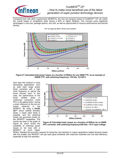
Compared even with other superjunction MOSFETs, the very low dynamic losses of CoolMOS <strong>CP</strong> can match<br />
the overall losses of competitors while having a 60% or higher RDS[on]. This conveys some significant<br />
advantages in chip size, package options, and cost, as well as opportunities to improve performance and thermal<br />
density.<br />
ITTF: one stage with 500 W, 130 kHz, hard sw @ 200 V<br />
4<br />
3<br />
conduction losses<br />
CoolMOS <strong>CP</strong> series<br />
Competitor A, conv MOS<br />
Competitor C<br />
capacitive losses <strong>CP</strong> series<br />
Competitor A, SJ<br />
Competitor B<br />
Competitor D<br />
Power losses [W]<br />
2<br />
1<br />
0<br />
0 50 100 150 200 250 300<br />
RDSon [mOhm]<br />
Figure 21 Calculated total power losses as a function of RDSon for one 500W TTF, as an example of<br />
1000W ITTF, with switching frequency= 130 kHz, Tj=105°C.<br />
How does this workout in more<br />
demanding applications, such<br />
as wide input range power<br />
factor correction with a high<br />
clock frequency to reduce the<br />
boost inductor size? In this<br />
case, the performance of the<br />
boost rectifier diode in<br />
continuous conduction mode<br />
PFC is the gating factor- having<br />
a direct influence on the turn-on<br />
losses observed in the<br />
MOSFET. By using a thinQ!<br />
2G silicon carbide Schottky<br />
diode, a nearly ideal diode is<br />
possible, and the switching<br />
losses are governed mostly by<br />
the MOSFET capabilities. The<br />
results are seen in the graph of<br />
Figure 22, which shows the<br />
possibility of matching power<br />
losses at full load with a<br />
MOSFET of much higher<br />
Power losses [W]<br />
20<br />
15<br />
10<br />
5<br />
0<br />
conduction losses<br />
capacitive losses<br />
CoolMOS <strong>CP</strong> 600 V series<br />
CoolMOS C3 600 V series<br />
Comp A, SJ, 500 V<br />
Comp B, conv MOSFET, 500 V<br />
0 50 100 150 200 250 300<br />
RDSon [mOhm]<br />
Figure 22 Calculated total Losses as a function of RDSon for an 800W<br />
PFC converter, with switching frequency=250 kHz, 110 V input voltage.<br />
RDSon. Besides the economic reasons for doing this, the reduction in output capacitance related dynamic losses<br />
with the smaller chip MOSFET will pay back good dividends with improved moderate and low load efficiency,<br />
especially at high line operation.<br />
18 of 32


