TCM1 V4.1.qxp - Philippi
TCM1 V4.1.qxp - Philippi
TCM1 V4.1.qxp - Philippi

You also want an ePaper? Increase the reach of your titles
YUMPU automatically turns print PDFs into web optimized ePapers that Google loves.
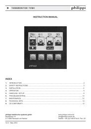
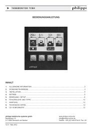
k TANKMONITOR TCM 1 & 2<br />
INSTRUCTION MANUAL<br />
INDEX<br />
1. INTRODUCTION.....................................................................................................................................2<br />
2. SAFETY INSTRUCTIONS ......................................................................................................................4<br />
3. INSTALLATION.......................................................................................................................................4<br />
4. OPERATION........................................................................................................................................... 6<br />
5. HANDLING..............................................................................................................................................7<br />
6. SETUP.................................................................................................................................................... 8<br />
7. TROUBLESHOOTING..........................................................................................................................10<br />
8. MAINTENANCE....................................................................................................................................11<br />
9. TECHNICAL DATA................................................................................................................................11<br />
10. CE-CONFORMITY.................................................................................................................................11<br />
philippi elektrische systeme gmbh<br />
www. philippi-online.de<br />
Neckaraue 19<br />
info@philippi-online.de<br />
D-71686 Remseck am Neckar Telefon: +49 (0)7146/8744-0, Fax -22<br />
V4.2 - May 2012
k TANKMONITOR TCM 1 & 2<br />
1. INTRODUCTION<br />
Dear customer,<br />
thank you for buying the tankmonitor TCM 1 / TCM 2. This digital unit is state of the art in<br />
tank monitoring.<br />
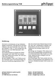
On the large, illuminated display you can read:<br />
x the actual filling level of up to three tanks<br />
x the voltage of up to two battery banks<br />
The tank levels are shown as a bar and in % or litres.<br />
The TCM is easy to operate and well readable. You have a quick overview of up to three<br />
tank levels and two battery voltages.<br />
For level-sensoring we recommend the sensors of our TGT / TGW - series, the ultrasonic<br />
sensors UTV and the fresh water flow sensor DFS (TCM 2). These sensors are not part of<br />
the purchased parts package.<br />
Sensors of other manufacturers can be connected as well; depending on the type you may<br />
need a hardware adaption at our company.<br />
In the SETUP- menu the display will be configurated to the connected sensors. Also you have<br />
the possibility to adjust the tankmonitor to your given tank - geometry to show the real tank<br />
filling level correctly.<br />
The acquiring data is made in intervals of time targeting the optimum rate information/energy<br />
consumption.<br />
When the battery voltage decreases below 12V, the acquiring rate is reduced in order to save<br />
energy.<br />
Please note: only when using the flow sensors DFS the shown display of litres is correct,<br />
because it measures the flowed litres. If you`re using other sensors, the TCM<br />
calculates the remaining tank capacity by the tank volume and the actual level.<br />
Depending on the accuracy of the sensors it cannot be litre-correct.<br />
Please, read the Instruction Manual carefully and follow all instructions before putting<br />
the equipment in operation.<br />
1.1. PURPOSE<br />
The tankmonitors of the TCM-series can only be used with suitable tank sensors for low voltage<br />
purposes DC 10-30V. They were designed for the use on yachts or camper vans and<br />
must be used in an enclosed environment which is protected against rain, moisture, dust and<br />
condensation. Don`t use the TCM tankmonitors in places where there could be danger of<br />
explosion by gas or dust.<br />
Page 2 V4.2 - May 2012
k TANKMONITOR TCM 1 & 2<br />
1.2.CONTENT<br />
x Tankmonitor TCM 1 or TCM 2<br />
x Plug-in clamp<br />
x This Instruction Manual<br />
1.3. ACCESSORIES (TO BE ORDERED SEPARATELY)<br />
x Flow sensor for fresh water DFS Ord.-Nr.: 7 0003 0304<br />
x Tank sensor TGT / TGW 200-800 Ord.-Nr.: 6 6011 7xxx<br />
x Ultrasonic tank sensor UTV 20-80 Ord.-Nr.: 7 0219 35xx<br />
1.4. WARRANTY<br />
philippi elektrische systeme gmbh grants a two year limited and not transferable warranty for<br />
the first buyer of this equipment, commencing on the date of purchase and covers defects in<br />
manufacturing, parts and materials.<br />
Production or material defects will be corrected without costs if:<br />
x the equipment will be send to us at the expense of the sender<br />
x enclose the receipt (copy) of purchase<br />
x the equipment was treated in the intended use<br />
x no strange spare parts were built in or external effects happened<br />
Not included in the warranty are damages from:<br />
x overvoltage in the inputs or reverse polarity<br />
x entered liquids in the device or oxydation through condensation<br />
x lightning<br />
Not under warranty are follow-up costs and normal wear and tear.<br />
In case of warranty there must be a specification of the defect. A detailed description<br />
of the defect will ease and speed up the repair.<br />
Please note that we cannot accept carriage forward deliveries.<br />
1.5. EXCLUSION OF LIABILITY<br />
Both the adherence to the operating instruction, and the conditions and methods during<br />
installation, using and maintenance of the TCM cannot be supervised by philippi electrical<br />
systems. Therefore we do not take any responsibility for loss, damage or costs, which develop<br />
due to incorrect installation and/or inappropriate enterprise.<br />
1.6. QUALITY MANAGEMENT<br />
During the process of manufacturing all devices pass several checks, controls and tests.<br />
Production, controls and tests are due to given protocols.<br />
The assembly and testing of all TCM devices is carried out completely in our company at<br />
Remseck am Neckar.<br />
V4.2 - May 2012 Page 3
k TANKMONITOR TCM 1 & 2<br />
2. SAFETY REFERENCES<br />
x unautorised change to the equipment will invalidate the CE sign<br />
x the installation of the TCM may be made only by electrical specialists.<br />
x Important! Pay attention to the correct polarity of the batteries!<br />
The assembly and operating instruction is a component of the TCM package.<br />
It must be kept (for reference). Importantly: - for later maintenance work - and for<br />
the use of subsequent owners of the equipment.<br />
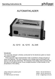
3. INSTALLATION<br />
Please install the TCM in a visible place, so that it can be read off at any time.<br />
The necessary installation cutout is 88 x 88mm, the necessary minimum depth is 40mm.<br />
The TCM supervises up to three tanks at the same time. If you have less sensors, start<br />
connecting the first sensor at terminal TG 1 ( if you`re using two, connect them to TG 1 and<br />
TG 2 and so on)<br />
You can use both passive (resistance) and active (ultrasonic) sensors at the same<br />
time. For the connection have a look at the connection diagramms.<br />
The flow sensor DFS has to be connected to terminal TG1 (only TCM 2)!<br />
If you want to use tank sensors with an output of 4-20mA or 0-10V you need a<br />
hardware-adaption at our company. Please ask.<br />
The power supply of the TCM is either directly from the battery or over a power distribution<br />
panel. Use a cable 1,5mm² cross section which has to be fused (1A).<br />
The display is lit when you press a button or you can connect the terminal “Light” to a switch<br />
and switch it on/off manually.<br />
The sense lines for the voltage measurement (Serv-B+ / Start-B+) has to be connected to<br />
the plus-poles of the relating batteries via fuses located near to the batteries.<br />
ServB+<br />
StartB+<br />
frei(nc)<br />
TG 3<br />
TG 2<br />
TG 1<br />
GND -<br />
DFS +<br />
UTV +<br />
12/24V<br />
GND -<br />
Light<br />
Page 4 V4.2 - May 2012
k TANKMONITOR TCM 1 & 2<br />
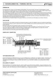
Connection of ultrasonic sensor UTV or over active sensors:<br />
ATTENTION:<br />
If the power supply of an ultrasonic<br />
sensor is connected directly to the on<br />
board DC system, not through the tankmonitor,<br />
this connection wire has to be<br />
fused by an 1A fuse!<br />
ServB+<br />
StartB+<br />
frei(nc)<br />
TG 3<br />
TG 2<br />
TG 1<br />
GND -<br />
DFS +<br />
UTV +<br />
12/24V<br />
GND -<br />
Light<br />
Connection of passive (resistance) sensors like TGT / TGW and other:<br />
ServB+<br />
StartB+<br />
frei(nc)<br />
TG 3<br />
TG 2<br />
TG 1<br />
GND -<br />
DFS +<br />
UTV +<br />
12/24V<br />
GND -<br />
Light<br />
Connection of flow sensors DFS (only TCM 2):<br />
ServB+<br />
StartB+<br />
frei(nc)<br />
TG 3<br />
TG 2<br />
TG 1<br />
GND -<br />
DFS +<br />
UTV +<br />
12/24V<br />
GND -<br />
Light<br />
V4.2 - May 2012 Page 5
k TANKMONITOR TCM 1 & 2<br />
4. OPERATION<br />
The display shows the tank levels automatically after switching on.<br />
In the SETUP-menu you can adjust each tank-display individually to the medium<br />
(fuel, water...), to the type of sensor used and to the compensation value for the tankgeometry.<br />
In case of a power supply breakdown all of these adjustments are saved and immediately<br />
available after switching on.<br />
While switching on the actual software-revision is shown in the tanks (starting from software<br />
rev.F April 2011).<br />
The measured levels are shown in a bar diagram and additonally either in litres or in percent.<br />
LOW- & HIGH- BATTERY VOLTAGE ALARM<br />
A warning symbol is displayed when the displayed voltage of the service or<br />
the start battery decreases below 11,5V / 23V ( 12V/24V ). or increases<br />
over 15V / 30V (12V/24V).<br />
(Alarmthreshold before software F: 10,8V / 21,6V)<br />
Page 6 V4.2 - May 2012
k TANKMONITOR TCM 1 & 2<br />
5. HANDLING<br />
When pressing the push buttons the display light is lit during 30 s. If you connect the<br />
terminal “Light” to the power supply via the power distribution panel the light can be<br />
activated manually.<br />
The alarm can be acknowledged by pressing a button.<br />
Following actions are activated by pressing:<br />
Starting from software Rev.F (April 2011):<br />
Button 1 Button 2 Button 3 Button 4<br />
Button 1 Long pressing (10s) Setup for tank 1<br />
Short pressing (1s)<br />
Tank is being filled up in 10% steps until the<br />
maximum value (only TCM2 - flow sensor)<br />
Button 2 Long pressing (10s) Setup for tank 2 (only if amount of tanks > 1)<br />
Button 3 Long pressing (10s) Setup for tank 3 (only if amount of tanks > 2)<br />
Button 4 Short pressing (1s) Change of the displayed battery voltage.<br />
(Service or start)<br />
Long pressing (10 s)<br />
Basic SETUP of tank type, -capacity, contrast,<br />
language and display<br />
V4.2 - May 2012 Page 7
k TANKMONITOR TCM 1 & 2<br />
6. SETUP<br />
In the SETUP-menu all adjustments can be changed:<br />
Following is the key function:<br />
Arrow:<br />
Plus:<br />
Minus:<br />
Return:<br />
selection of the line to be<br />
modified<br />
increase the value<br />
decrease the value<br />
save the values and return to<br />
the tank display<br />
BASIC SETTINGS<br />
Number of tanks 3 (reducing to the display of only 2 tanks is possible -<br />
see page 9)<br />
Display<br />
0 = display of the remaining tank capacity in litres (l)<br />
1 = display of the remaining tank capacity in percentage (%)<br />
Language<br />
Language for the SETUP-menu. Available are following<br />
languages: German / English / French<br />
Contrast<br />
Display contrast attitude + = dimmer, - = brighter<br />
In the tank menu you can adjust the tank type<br />
(e.g. water, fuel, waste and the type of the sensor),<br />
the capacity and the compensation-value<br />
(adjustment of the tank-geometry).<br />
The inverted line can be changed.<br />
Page 8 V4.2 - May 2012
k TANKMONITOR TCM 1 & 2<br />
ADJUSTMENTS OF THE TANK DISPLAY:<br />
Capacity of the tank<br />
By pressing the +/- - button you can adjust the capacity of<br />
the tank. The capacity is displayed in litres.<br />
Tanktype (Tank 1- 3) 5 differents tank symbols are available for each tank:<br />
Fresh Water Fuel Waste Water Grey-water Gas<br />
Tanktype Sensor Measurement range Attention<br />
00 01 02 03 04 philippi TRG 6 levels (6..190 Ohm)<br />
05 06 07 08 09 philippi TGT / TGW 5..180 Ohm<br />
10 11 12 13 14 philippi UTV 0,5..2,5V<br />
10 11 12 13 14 philippi UTA 4..20mA Hardware adjustment!<br />
15 16 17 18 19 0..10 V Hardware adjustment!<br />
20 21 22 23 24 240..33 Ohm UTR not possible!<br />
25 26 27 28 29 300..10 Ohm<br />
30 31 32 33 34 90..0 Ohm<br />
35 36 37 38 39 0..90 Ohm<br />
40 41 42 43 44 5 Stab Büschelgeber 4 levels Auxiliary hardware PB43!<br />
Incorrect display information can occur due to not compatible parts. Please ensure that the<br />
tank type matches the sensor.<br />
Starting from software Rev.F (April 2011):<br />
Tanktype 50 - DFS (only TCM 2) for tank 1:<br />
after filling up of the tank the shown content is being filled up in 10% steps until the<br />
maximum value by pressing of the button 1.<br />
Tanktype 45 (only TCM 1)- displayed tank can be erased :<br />
in case you want to display only the content of two tanks, you can erase the content and<br />
symbol of tank 3 by choosing the tanktype 45 in the setup of tank 3. Then only an empty<br />
tank is shown.<br />
V4.2 - May 2012 Page 9
k TANKMONITOR TCM 1 & 2<br />
7. TROUBLESHOOTING<br />
Compensation (Tank 1-3)<br />
Tank1...3 : Adjustment of tank geometry<br />
With non rectangular tanks the level height is not proportional to<br />
the content of liquid in the tank. By means of the compensation<br />
value this can be considered in the display. The compensation<br />
value changes the tank characteristic in such a way that the<br />
indicated level is approximated to geometry of the tank.<br />
The value to be entered is value the tank display should indicate<br />
with the half level height of the tank is. The following examples<br />
shows which values the compensation value with different geometry<br />
will be:<br />
If tank geometry is strongly deviating from the examples, then<br />
the correction value can be determined.<br />
The correction value is computes by capacity of level iof half<br />
height divided by the capacity of entire level in the tank multiplyied<br />
by 100.<br />
Capacity of half level height<br />
Correction value K = ------------------------------------ x 100<br />
Level of fuel in the tank entirely<br />
Example: The tank has a total volume of 150 l with a maximum<br />
filling height (tank height) of 50 cm.<br />
In order to determine the correction value, the tank is filled up<br />
only up to the half filling height (= 25 cm). Computationally or by<br />
filling up a value of 65 l results.<br />
Inserted into the formula results for the correction value a value<br />
of:<br />
K = 65 l/150 l x 100 = 43<br />
This is deposited accordingly now in the Setup.<br />
If the tankmonitor shows wrong values, please check first the sensor and the correct connection<br />
of the sensor. Check also the wiring between the sensor and the tankmonitor. This is the<br />
main source of defect. If the shown values are totally implausible, check the supply voltage<br />
of the sensors. The supply voltage has to be min. 10V (see the data sheet of the sensor).<br />
Page 10 V4.2 - May 2012
k TANKMONITOR TCM 1 & 2<br />
8. MAINTENANCE<br />
The tank monitor does not request special maintenance. The frontpanel can be cleaned with<br />
a damp cloth without using agressive detergents.<br />
9. TECHNICAL DATA<br />
Power supply<br />
Power consumption<br />
Dimensions:<br />
Installation cutout:<br />
DC 10-30 Volt<br />
ca. 8mA when using resistance sensors,<br />
60mA if the display is lit (12V)<br />
12mA when using a flow sensor DFS<br />
when using ultrasonic sensors UTV:<br />
50 mA per sensor<br />
105 x 105 x 40 mm<br />
88 x 88 mm<br />
10. CE-CONFORMITY<br />
philippi elektrische systeme gmbh<br />
Neckaraue 19<br />
71686 Remseck am Neckar<br />
Germany<br />
certifies herewith, that the products: Tankmonitor TCM 1 / TCM 2<br />
fulfill the requirements of the European Regulation 2004/108/EG<br />
Following harmonised standards were implemented:<br />
Immunity: EN 61000-6-1:2007<br />
Emission: EN 61000-6-3:2007<br />
Remseck, January 2008<br />
Dipl.-Ing. Michael Kögel<br />
general manager philippi<br />
V4.2 - May 2012 Page 11
k TANKMONITOR TCM 1 & 2<br />
Own adjustments:<br />
Tank Type Capacity(l) Type of sensor<br />
Fresh water<br />
1 Fuel<br />
Grey water<br />
Waste water<br />
Gas<br />
Fresh water<br />
1 Fuel<br />
Grey water<br />
Waste water<br />
Gas<br />
Fresh water<br />
1 Fuel<br />
Grey water<br />
Waste water<br />
Gas<br />
Tank Type Capacity(l) Type of sensor<br />
Fresh water<br />
1 Fuel<br />
Grey water<br />
Waste water<br />
Gas<br />
Fresh water<br />
1 Fuel<br />
Grey water<br />
Waste water<br />
Gas<br />
Fresh water<br />
1 Fuel<br />
Grey water<br />
Waste water<br />
Gas