CAEN V767 128 Channel Gen. Purpose MH TDC - Physics
CAEN V767 128 Channel Gen. Purpose MH TDC - Physics
CAEN V767 128 Channel Gen. Purpose MH TDC - Physics

You also want an ePaper? Increase the reach of your titles
YUMPU automatically turns print PDFs into web optimized ePapers that Google loves.
02/07/2003 <strong>V767</strong> User's Manual – Rev.4<br />
1. DESCRIPTION<br />
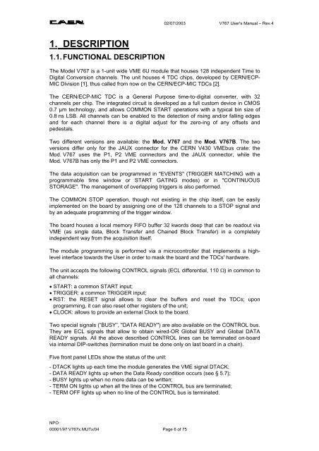
1.1. FUNCTIONAL DESCRIPTION<br />
The Model <strong>V767</strong> is a 1-unit wide VME 6U module that houses <strong>128</strong> independent Time to<br />
Digital Conversion channels. The unit houses 4 <strong>TDC</strong> chips, developed by CERN/ECP-<br />
MIC Division [1], thus called from now on the CERN/ECP-MIC <strong>TDC</strong>s [2].<br />
The CERN/ECP-MIC <strong>TDC</strong> is a <strong>Gen</strong>eral <strong>Purpose</strong> time-to-digital converter, with 32<br />
channels per chip. The integrated circuit is developed as a full custom device in CMOS<br />
0.7 µm technology, and allows COMMON START operations with a typical bin size of<br />
0.8 ns LSB. All channels can be enabled to the detection of rising and/or falling edges<br />
and for each channel there is a digital adjust for the zero-ing of any offsets and<br />
pedestals.<br />
Two different versions are available: the Mod. <strong>V767</strong> and the Mod. <strong>V767</strong>B. The two<br />
versions differ only for the JAUX connector for the CERN V430 VMEbus crate: the<br />
Mod. <strong>V767</strong> uses the P1, P2 VME connectors and the JAUX connector, while the<br />
Mod. <strong>V767</strong>B has only the P1 and P2 VME connectors.<br />
The data acquisition can be programmed in "EVENTS" (TRIGGER MATCHING with a<br />
programmable time window or START GATING modes) or in "CONTINUOUS<br />
STORAGE". The management of overlapping triggers is also performed.<br />
The COMMON STOP operation, though not existing in the chip itself, can be easily<br />
implemented on the board by assigning one of the <strong>128</strong> channels to a STOP signal and<br />
by an adequate programming of the trigger window.<br />
The board houses a local memory FIFO buffer 32 kwords deep that can be readout via<br />
VME (as single data, Block Transfer and Chained Block Transfer) in a completely<br />
independent way from the acquisition itself.<br />
The module programming is performed via a microcontroller that implements a highlevel<br />
interface towards the User in order to mask the board and the <strong>TDC</strong>s' hardware.<br />
The unit accepts the following CONTROL signals (ECL differential, 110 Ω) in common to<br />
all channels:<br />
• START: a common START input;<br />
• TRIGGER: a common TRIGGER input;<br />
• RST: the RESET signal allows to clear the buffers and reset the <strong>TDC</strong>s; upon<br />
programming, it can also reset other registers of the unit;<br />
• CLOCK: allows to provide an external Clock to the board.<br />
Two special signals (“BUSY”, "DATA READY") are also available on the CONTROL bus.<br />
They are ECL signals that allow to obtain wired-OR Global BUSY and Global DATA<br />
READY signals. All the above described CONTROL lines can be terminated on-board<br />
via internal DIP-switches (termination must be done only on last board in a chain).<br />
Five front panel LEDs show the status of the unit:<br />
- DTACK lights up each time the module generates the VME signal DTACK;<br />
- DATA READY lights up when the Data Ready condition occurs (see § 5.7);<br />
- BUSY lights up when no more data can be written;<br />
- TERM ON lights up when all the lines of the CONTROL bus are terminated;<br />
- TERM OFF lights up when no line of the CONTROL bus is terminated.<br />
NPO:<br />
00001/97:<strong>V767</strong>x.MUTx/04 Page 6 of 75