CAEN V767 128 Channel Gen. Purpose MH TDC - Physics
CAEN V767 128 Channel Gen. Purpose MH TDC - Physics
CAEN V767 128 Channel Gen. Purpose MH TDC - Physics

Create successful ePaper yourself
Turn your PDF publications into a flip-book with our unique Google optimized e-Paper software.
Technical<br />
Information<br />
Manual<br />
Revision n. 4<br />
2 July 2003<br />
NPO:<br />
0000197:<strong>V767</strong>x.MUTx/04<br />
MOD. <strong>V767</strong><br />
<strong>128</strong> CH.<br />
GENERAL PURPOSE<br />
MULTIHIT <strong>TDC</strong>
02/07/2003 <strong>V767</strong> User's Manual – Rev.4<br />
TABLE OF CONTENTS<br />
TABLE OF CONTENTS.......................................................................................................................................... 2<br />
LIST OF FIGURES ................................................................................................................................................. 5<br />
LIST OF TABLES ................................................................................................................................................... 5<br />
1. DESCRIPTION ......................................................................................................................................... 6<br />
1.1. FUNCTIONAL DESCRIPTION................................................................................................... 6<br />
1.2. PRINCIPLES OF OPERATION.................................................................................................. 8<br />
1.2.1. STOP TRIGGER MATCHING.................................................................................... 8<br />
1.2.2. START TRIGGER MATCHING.................................................................................. 9<br />
1.2.3. START GATING ........................................................................................................ 10<br />
1.2.4. CONTINUOUS STORAGE ........................................................................................ 11<br />
1.2.5. COMMON STOP EMULATION ................................................................................. 12<br />
2. SPECIFICATIONS.................................................................................................................................... 13<br />
2.1. PACKAGING.............................................................................................................................. 13<br />
2.2. EXTERNAL COMPONENTS...................................................................................................... 13<br />
2.3. INTERNAL COMPONENTS....................................................................................................... 13<br />
2.4. CHARACTERISTICS OF THE SIGNALS................................................................................... 14<br />
2.5. GENERAL .................................................................................................................................. 14<br />
2.6. POWER REQUIREMENTS........................................................................................................ 14<br />
3. VME INTERFACE .................................................................................................................................... 19<br />
3.1. ADDRESSING CAPABILITY...................................................................................................... 19<br />
3.1.1. ADDRESSING VIA BASE ADDRESS........................................................................ 19<br />
3.1.2. ADDRESSING VIA GEOGRAPHICAL ADDRESS..................................................... 20<br />
3.1.3. BASE/GEO ADDRESSING EXAMPLE...................................................................... 20<br />
3.1.4. MCST/CBLT ADDRESSING...................................................................................... 21<br />
3.1.5. MCST/CBLT ADDRESSING EXAMPLE .................................................................... 21<br />
3.2. INTERRUPTER CAPABILITY .................................................................................................... 24<br />
3.2.1. INTERRUPT STATUS/ID........................................................................................... 24<br />
3.2.2. INTERRUPT LEVEL .................................................................................................. 24<br />
3.2.3. INTERRUPT GENERATION...................................................................................... 24<br />
3.2.4. INTERRUPT REQUEST RELEASE........................................................................... 24<br />
3.3. DATA TRANSFER CAPABILITY................................................................................................ 25<br />
3.4. OUTPUT BUFFER ..................................................................................................................... 28<br />
3.5. GEOGRAPHICAL REGISTER ................................................................................................... 29<br />
3.6. BIT SET REGISTER .................................................................................................................. 29<br />
3.7. BIT CLEAR REGISTER ............................................................................................................. 30<br />
3.8. INTERRUPT LEVEL REGISTER ............................................................................................... 30<br />
3.9. INTERRUPT VECTOR REGISTER............................................................................................ 30<br />
3.10. STATUS REGISTER 1............................................................................................................... 31<br />
3.11. CONTROL REGISTER 1 ........................................................................................................... 32<br />
3.12. ADDRESS DECODER REGISTER 32....................................................................................... 32<br />
3.13. ADDRESS DECODER REGISTER 24....................................................................................... 33<br />
3.14. MCST ADDRESS REGISTER.................................................................................................... 33<br />
3.15. SINGLE SHOT RESET REGISTER........................................................................................... 33<br />
3.16. MCST CONTROL REGISTER ................................................................................................... 33<br />
3.17. STATUS REGISTER 2............................................................................................................... 34<br />
3.18. CONTROL REGISTER 2 ........................................................................................................... 35<br />
3.19. EVENT COUNTER REGISTER ................................................................................................. 35<br />
3.20. CLEAR EVENT COUNTER REGISTER .................................................................................... 36<br />
3.21. OPCODE HANDSHAKE REGISTER ......................................................................................... 36<br />
3.22. OPCODE REGISTER ................................................................................................................ 36<br />
3.23. CLEAR REGISTER .................................................................................................................... 36<br />
3.24. TESTWORD_HIGH REGISTER ................................................................................................ 37<br />
3.25. TESTWORD_LOW REGISTER ................................................................................................. 37<br />
3.26. SOFTWARE TRIGGER REGISTER .......................................................................................... 37<br />
4. OPERATING CODES............................................................................................................................... 38<br />
4.1. PROGRAMMING CAPABILITY.................................................................................................. 38<br />
4.2. TEST OPCODES ....................................................................................................................... 44<br />
4.2.1. ENABLE MEMORY TEST MODE (CODE 01xx)........................................................ 44<br />
4.2.2. DISABLE MEMORY TEST MODE (CODE 02xx)....................................................... 44<br />
4.2.3. READ MEMORY TEST ON/OFF (CODE 03xx)......................................................... 44<br />
4.3. ACQUISITION MODE OPCODES ............................................................................................. 44<br />
4.3.1. SET STOP TRIGGER MATCHING (CODE 10xx) ..................................................... 44<br />
4.3.2. SET START TRIGGER MATCHING (CODE 11xx) ................................................... 44<br />
NPO:<br />
00001/97:<strong>V767</strong>x.MUTx/04 Page 2 of 75
02/07/2003 <strong>V767</strong> User's Manual – Rev.4<br />
4.3.3. SET START GATING (CODE 12xx) .......................................................................... 44<br />
4.3.4. SET CONTINUOUS STORAGE (CODE 13xx) .......................................................... 44<br />
4.3.5. READ ACQUISITION MODE (CODE 14xx)............................................................... 45<br />
4.3.6. LOAD DEFAULT CONFIGURATION (CODE 15xx)................................................... 45<br />
4.3.7. SAVE USER CONFIGURATION (CODE 16xx) ......................................................... 45<br />
4.3.8. LOAD USER CONFIGURATION (CODE 17xx)......................................................... 45<br />
4.3.9. ENABLE AUTO LOAD (CODE 18xx)......................................................................... 45<br />
4.3.10. DISABLE AUTO LOAD (CODE 19xx)........................................................................ 45<br />
4.3.11. READ AUTO LOAD (CODE 1Axx)............................................................................. 45<br />
4.4. CHANNEL ENABLE OPCODES ................................................................................................ 46<br />
4.4.1. ENABLE CHANNEL nn (CODE 20nn) ....................................................................... 46<br />
4.4.2. DISABLE CHANNEL nn (CODE 21nn) ...................................................................... 46<br />
4.4.3. READ STATUS CHANNEL nn (CODE 22nn) ............................................................ 46<br />
4.4.4. ENABLE ALL CHANNELS (CODE 23xx)................................................................... 46<br />
4.4.5. DISABLE ALL CHANNELS (CODE 24xx).................................................................. 46<br />
4.4.6. WRITE ENABLE PATTERN (CODE 25xx) ................................................................ 47<br />
4.4.7. READ ENABLE/DISABLE WORDS (CODE 26xx)..................................................... 47<br />
4.5. TRIGGER OPCODES ................................................................................................................ 48<br />
4.5.1. SET WINDOW WIDTH (CODE 30xx) ........................................................................ 48<br />
4.5.2. READ WINDOW WIDTH (CODE 31xx) ..................................................................... 48<br />
4.5.3. SET WINDOW OFFSET (CODE 32xx)...................................................................... 48<br />
4.5.4. READ WINDOW OFFSET (CODE 33xx)................................................................... 49<br />
4.5.5. SET TRIGGER LATENCY (CODE 34xx)................................................................... 49<br />
4.5.6. READ TRIGGER LATENCY (CODE 35xx)................................................................ 49<br />
4.5.7. ENABLE SUBTRACTION OF TRIGGER TIME (CODE 36xx) ................................... 49<br />
4.5.8. DISABLE SUBTRACTION OF TRIGGER TIME (CODE 37xx) .................................. 49<br />
4.5.9. ENABLE OVERLAPPING TRIGGERS (CODE 38xx) ................................................ 49<br />
4.5.10. DISABLE OVERLAPPING TRIGGERS (CODE 39xx) ............................................... 49<br />
4.5.11. READ TRIGGER CONFIGURATION (CODE 3Axx) .................................................. 49<br />
4.6. START OPCODES..................................................................................................................... 50<br />
4.6.1. ENABLE READOUT OF START TIME (CODE 40xx)................................................ 50<br />
4.6.2. ENABLE READOUT OF 4 START TIMES (CODE 41xx) .......................................... 50<br />
4.6.3. DISABLE READOUT OF START TIME (CODE 42xx)............................................... 50<br />
4.6.4. ENABLE SUBTRACTION OF START TIME (CODE 43xx)........................................ 50<br />
4.6.5. DISABLE SUBTRACTION OF START TIME (CODE 44xx)....................................... 50<br />
4.6.6. ENABLE EMPTY START (CODE 45xx) .................................................................... 50<br />
4.6.7. DISABLE EMPTY START (CODE 46xx) ................................................................... 50<br />
4.6.8. READ START CONFIGURATION (CODE 47xx)....................................................... 50<br />
4.7. ADJUST OPCODES .................................................................................................................. 51<br />
4.7.1. SET CHANNEL NN ADJUST (CODE 50nn) .............................................................. 51<br />
4.7.2. READ CHANNEL NN ADJUST (CODE 51nn) ........................................................... 51<br />
4.7.3. SET GLOBAL OFFSET (CODE 52xx) ....................................................................... 51<br />
4.7.4. READ GLOBAL OFFSET (CODE 53xx) .................................................................... 52<br />
4.7.5. ENABLE CHANNEL ADJUST (CODE 54xx).............................................................. 52<br />
4.7.6. DISABLE CHANNEL ADJUST (CODE 55xx)............................................................. 52<br />
4.7.7. RESET ALL ADJUSTS (CODE 56xx) ........................................................................ 52<br />
4.7.8. READ ENABLE ADJUSTS (CODE 57xx) ................................................................. 52<br />
4.8. EDGE DETECTION OPCODES................................................................................................. 52<br />
4.8.1. RISING EDGE ONLY ON ALL CHANNELS (CODE 60xx) ........................................ 52<br />
4.8.2. FALLING EDGE ONLY ON ALL CHANNELS (CODE 61xx)...................................... 52<br />
4.8.3. RISING EDGE ON ODD CH., FALLING EDGE ON EVEN (CODE 62xx).................. 52<br />
4.8.4. FALLING EDGE ON ODD CH., RISING EDGE ON EVEN (CODE 63xx).................. 52<br />
4.8.5. RISING EDGE ONLY START (CODE 64xx).............................................................. 53<br />
4.8.6. FALLING EDGE ONLY START (CODE 65xx) ........................................................... 53<br />
4.8.7. BOTH EDGES ON ALL CHANNELS (CODE 66xx) ................................................... 53<br />
4.8.8. READ EDGE DETECTION CONFIGURATION (CODE 67xx)................................... 53<br />
4.9. DATA READY OPCODES ......................................................................................................... 53<br />
4.9.1. SET D.R. = EVENT READY (CODE 70xx) ................................................................ 53<br />
4.9.2. SET D.R. = BUFFER ALMOST FULL (CODE 71xx).................................................. 53<br />
4.9.3. SET D.R. = BUFFER NOT EMPTY (CODE 72xx) ..................................................... 54<br />
4.9.4. READ DATA READY MODE (CODE 73xx) ............................................................... 55<br />
4.9.5. SET ALMOST FULL LEVEL (CODE 74xx) ................................................................ 55<br />
4.9.6. READ ALMOST FULL LEVEL (CODE 75xx) ............................................................. 55<br />
4.10. JTAG OPCODES ....................................................................................................................... 55<br />
4.10.1. READ ERROR CODE OF <strong>TDC</strong> C (CODE 80xc)....................................................... 55<br />
4.10.2. READ ID CODE OF <strong>TDC</strong> C (CODE 81xc)................................................................ 56<br />
4.10.3. WRITE JTAG SETUP REGISTER OF <strong>TDC</strong> C (INT. USE) (CODE 82xc) ................. 56<br />
NPO:<br />
00001/97:<strong>V767</strong>x.MUTx/04 Page 3 of 75
02/07/2003 <strong>V767</strong> User's Manual – Rev.4<br />
4.11. REJECT OLD DATA OPCODES................................................................................................ 56<br />
4.11.1. SET REJECT OFFSET (CODE 90xx)........................................................................ 56<br />
4.11.2. READ REJECT OFFSET (CODE 91xx)..................................................................... 56<br />
4.11.3. ENABLE AUTOMATIC REJECT (CODE 92xx).......................................................... 56<br />
4.11.4. DISABLE AUTOMATIC REJECT (CODE 93xx)......................................................... 56<br />
4.11.5. READ ENABLE REJECT (CODE 94xx)..................................................................... 56<br />
4.12. TRIGGER SEARCH WINDOW OPCODES ............................................................................... 57<br />
4.12.1. SET LOOK AHEAD WINDOW (CODE A0xx) ............................................................ 57<br />
4.12.2. READ LOOK AHEAD WINDOW (CODE A1xx) ......................................................... 57<br />
4.12.3. SET LOOK BACK WINDOW (CODE A2xx)............................................................... 57<br />
4.12.4. READ LOOK BACK WINDOW (CODE A3xx)............................................................ 57<br />
4.13. ADVANCED OPCODES............................................................................................................. 57<br />
4.13.1. SET DLL CURRENT (CODE B0xx) ........................................................................... 57<br />
4.13.2. READ DLL CURRENT (CODE B1xx) ........................................................................ 57<br />
4.13.3. RESET DLL (CODE B2xx)......................................................................................... 58<br />
4.13.4. ENABLE DOUBLE SYNCHRONIZER (CODE B3xx)................................................. 58<br />
4.13.5. DISABLE DOUBLE SYNCHRONIZER (CODE B4xx)................................................ 58<br />
4.13.6. ENABLE DOUBLE HIT PRIORITY (CODE B5xx)...................................................... 58<br />
4.13.7. DISABLE DOUBLE HIT PRIORITY (CODE B6xx)..................................................... 58<br />
4.13.8. READ ADVANCED CONFIGURATION (CODE B7xx) .............................................. 58<br />
4.13.9. SET ERROR MASK (CODE B8xx) ............................................................................ 58<br />
4.13.10. READ ERROR MASK (CODE B9xx) ......................................................................... 58<br />
5. OPERATING MODES .............................................................................................................................. 59<br />
5.1. INTRODUCTION........................................................................................................................ 59<br />
5.2. POWER-ON/RESET STATUS ................................................................................................... 59<br />
5.3. START AND TRIGGER INPUTS ............................................................................................... 59<br />
5.4. RESET INPUT............................................................................................................................ 60<br />
5.5. CLOCK INPUT ........................................................................................................................... 60<br />
5.6. BUSY OUTPUT.......................................................................................................................... 60<br />
5.7. DATA READY OUTPUT............................................................................................................. 60<br />
5.8. TRIGGER WINDOW DEFINITION............................................................................................. 61<br />
5.9. STOP TRIGGER MATCHING OPERATION.............................................................................. 61<br />
5.10. START TRIGGER MATCHING OPERATION............................................................................ 64<br />
5.11. START GATING OPERATION................................................................................................... 67<br />
5.12. CONTINUOUS STORAGE OPERATION................................................................................... 69<br />
5.13. COMMON STOP EMULATION OPERATION............................................................................ 71<br />
5.14. DATA BUFFER STRUCTURE ................................................................................................... 72<br />
5.15. BLOCK TRANSFER MODE ....................................................................................................... 72<br />
5.16. ADVANCED SETTING AND READOUT MODES...................................................................... 73<br />
5.16.1. CHAINED BLOCK TRANSFER MODE ......................................................................... 73<br />
5.16.2. MULTICAST COMMANDS............................................................................................ 74<br />
6. REFERENCES ......................................................................................................................................... 75<br />
NPO:<br />
00001/97:<strong>V767</strong>x.MUTx/04 Page 4 of 75
02/07/2003 <strong>V767</strong> User's Manual – Rev.4<br />
LIST OF FIGURES<br />
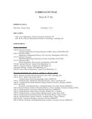
Fig. 1.1: Mod. <strong>V767</strong> Block Diagram ......................................................................................................................... 7<br />
Fig. 1.2: Stop Trigger Matching Sequence............................................................................................................... 8<br />
Fig. 1.3: Start Trigger Matching Sequence............................................................................................................... 9<br />
Fig. 1.4: Start Gating Sequence............................................................................................................................. 10<br />
Fig. 1.5: Continuous Storage Sequence ................................................................................................................ 11<br />
Fig. 1.6: Common Stop Emulation ......................................................................................................................... 12<br />
Fig. 1.7: Common Stop Sequence ......................................................................................................................... 12<br />
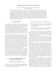
Fig. 2.1: Mod. <strong>V767</strong> Front Panel ............................................................................................................................ 15<br />
Fig. 2.2: INPUT connector pin assignment............................................................................................................. 16<br />
Fig. 2.3: INPUT connector cabling ......................................................................................................................... 17<br />
Fig. 2.4: Mod. <strong>V767</strong> Components Locations .......................................................................................................... 18<br />
Fig. 3.1: Base/GEO Addressing Example 1 ........................................................................................................... 20<br />
Fig. 3.2: MCST/CBLT Addressing Example........................................................................................................... 22<br />
Fig. 3.3: Mod. <strong>V767</strong> Base Address Setting ............................................................................................................ 25<br />
Fig. 3.4: Mod. <strong>V767</strong> Output Buffer Data Structure ................................................................................................. 28<br />
Fig. 3.5: GEO Address Register............................................................................................................................. 29<br />
Fig. 3.6: Bit Set Register ........................................................................................................................................ 29<br />
Fig. 3.7: Interrupt Level Register............................................................................................................................ 30<br />
Fig. 3.8: Interrupt Vector Register .......................................................................................................................... 30<br />
Fig. 3.9: Status Register 1 ..................................................................................................................................... 31<br />
Fig. 3.10: Control Register 1 .................................................................................................................................. 32<br />
Fig. 3.11: ADER 32 Register.................................................................................................................................. 32<br />
Fig. 3.12: ADER 24 Register.................................................................................................................................. 33<br />
Fig. 3.13: MCST Address Register ........................................................................................................................ 33<br />
Fig. 3.14: Control Register 1 .................................................................................................................................. 33<br />
Fig. 3.15: Status Register 2.................................................................................................................................... 34<br />
Fig. 3.16: Control Register 2 .................................................................................................................................. 35<br />
Fig. 3.17: Event Counter ........................................................................................................................................ 35<br />
Fig. 3.18: Opcode Handshake Register ................................................................................................................. 36<br />
Fig. 3.19: Opcode Register .................................................................................................................................... 36<br />
Fig. 3.20: TESTWORD_HIGH Register ................................................................................................................. 37<br />
Fig. 3.21: TESTWORD_LOW Register .................................................................................................................. 37<br />
Fig. 4.1: R/W operations: software logic blocks ..................................................................................................... 39<br />
Fig. 4.2: Mod. <strong>V767</strong> OPCODE Word...................................................................................................................... 41<br />
Fig. 4.3: Trigger Window: width and offset ............................................................................................................. 48<br />
Fig. 5.1: Trigger Window........................................................................................................................................ 61<br />
Fig. 5.2: Trigger Window to test Stop Trigger Matching operation mode ............................................................... 63<br />
Fig. 5.3: TRIGGER and HIT 0 signals to test Stop Trigger Matching operation mode ........................................... 64<br />
Fig. 5.4: TRIGGER, START and HIT 0 signals to test Start Trigger Matching mode ............................................. 66<br />
Fig. 5.5: START and HIT 0 signals to test Start Gating operation mode................................................................ 68<br />
Fig. 5.6: START, HIT 0 and HIT 1 signals to test Continuous Storage operation mode......................................... 70<br />
LIST OF TABLES<br />
Table 3.1: Address Map for the Mod. <strong>V767</strong>............................................................................................................ 26<br />
Table 3.2: Address Map for the Mod. <strong>V767</strong> in MCST operations ........................................................................... 27<br />
Table 3.3: Address Map for the Mod. <strong>V767</strong> in CBLT operations ............................................................................ 27<br />
Table 3.4: Address Map for the Mod. <strong>V767</strong> CR space (most relevant registers) ................................................... 27<br />
Table 4.1: OPCODE Words for the Mod. <strong>V767</strong>...................................................................................................... 42<br />
NPO:<br />
00001/97:<strong>V767</strong>x.MUTx/04 Page 5 of 75
02/07/2003 <strong>V767</strong> User's Manual – Rev.4<br />
1. DESCRIPTION<br />
1.1. FUNCTIONAL DESCRIPTION<br />
The Model <strong>V767</strong> is a 1-unit wide VME 6U module that houses <strong>128</strong> independent Time to<br />
Digital Conversion channels. The unit houses 4 <strong>TDC</strong> chips, developed by CERN/ECP-<br />
MIC Division [1], thus called from now on the CERN/ECP-MIC <strong>TDC</strong>s [2].<br />
The CERN/ECP-MIC <strong>TDC</strong> is a <strong>Gen</strong>eral <strong>Purpose</strong> time-to-digital converter, with 32<br />
channels per chip. The integrated circuit is developed as a full custom device in CMOS<br />
0.7 µm technology, and allows COMMON START operations with a typical bin size of<br />
0.8 ns LSB. All channels can be enabled to the detection of rising and/or falling edges<br />
and for each channel there is a digital adjust for the zero-ing of any offsets and<br />
pedestals.<br />
Two different versions are available: the Mod. <strong>V767</strong> and the Mod. <strong>V767</strong>B. The two<br />
versions differ only for the JAUX connector for the CERN V430 VMEbus crate: the<br />
Mod. <strong>V767</strong> uses the P1, P2 VME connectors and the JAUX connector, while the<br />
Mod. <strong>V767</strong>B has only the P1 and P2 VME connectors.<br />
The data acquisition can be programmed in "EVENTS" (TRIGGER MATCHING with a<br />
programmable time window or START GATING modes) or in "CONTINUOUS<br />
STORAGE". The management of overlapping triggers is also performed.<br />
The COMMON STOP operation, though not existing in the chip itself, can be easily<br />
implemented on the board by assigning one of the <strong>128</strong> channels to a STOP signal and<br />
by an adequate programming of the trigger window.<br />
The board houses a local memory FIFO buffer 32 kwords deep that can be readout via<br />
VME (as single data, Block Transfer and Chained Block Transfer) in a completely<br />
independent way from the acquisition itself.<br />
The module programming is performed via a microcontroller that implements a highlevel<br />
interface towards the User in order to mask the board and the <strong>TDC</strong>s' hardware.<br />
The unit accepts the following CONTROL signals (ECL differential, 110 Ω) in common to<br />
all channels:<br />
• START: a common START input;<br />
• TRIGGER: a common TRIGGER input;<br />
• RST: the RESET signal allows to clear the buffers and reset the <strong>TDC</strong>s; upon<br />
programming, it can also reset other registers of the unit;<br />
• CLOCK: allows to provide an external Clock to the board.<br />
Two special signals (“BUSY”, "DATA READY") are also available on the CONTROL bus.<br />
They are ECL signals that allow to obtain wired-OR Global BUSY and Global DATA<br />
READY signals. All the above described CONTROL lines can be terminated on-board<br />
via internal DIP-switches (termination must be done only on last board in a chain).<br />
Five front panel LEDs show the status of the unit:<br />
- DTACK lights up each time the module generates the VME signal DTACK;<br />
- DATA READY lights up when the Data Ready condition occurs (see § 5.7);<br />
- BUSY lights up when no more data can be written;<br />
- TERM ON lights up when all the lines of the CONTROL bus are terminated;<br />
- TERM OFF lights up when no line of the CONTROL bus is terminated.<br />
NPO:<br />
00001/97:<strong>V767</strong>x.MUTx/04 Page 6 of 75
02/07/2003 <strong>V767</strong> User's Manual – Rev.4<br />
The module houses a VME RORA INTERRUPTER[4]: the interrupt is generated on the<br />
occurrence (User programmable) of one of the following conditions:<br />
• at least one complete event is present in the buffer;<br />
• the buffer is not empty (at least one word is present in the buffer);<br />
• the buffer is almost full (programmable).<br />
The <strong>V767</strong> Model uses the P1 and P2 connectors of VME and the auxiliary connector for<br />
the CERN V430 VMEbus crate (Jaux Dataway) [5].<br />
The <strong>V767</strong>B Model uses the P1 and P2 connectors of VME only (i.e. it does not have the<br />
auxiliary connector for the CERN V430 VMEbus crate) and consequently hosts a DC-DC<br />
converter for the -5V power supply.<br />
The module works in A24/A32 mode; the recognized Address Modifier codes are:<br />
AM=%2F: A24 GEO access<br />
AM=%3F: A24 supervisory block transfer (BLT)<br />
AM=%3D: A24 supervisory data access<br />
AM=%3C: A24 supervisory 64-bit block transfer (MBLT)<br />
AM=%3B: A24 user block transfer (BLT)<br />
AM=%39: A24 user data access<br />
AM=%38: A24 user 64-bit block transfer (MBLT)<br />
AM=%0F: A32 supervisory block transfer (BLT)<br />
AM=%0D: A32 supervisory data access<br />
AM=%0C: A32 supervisory 64-bit block transfer (MBLT)<br />
AM=%0B: A32 user block transfer (BLT)<br />
AM=%09: A32 user data access<br />
AM=%08: A32 user 64-bit block transfer (MBLT)<br />
The module's Base Address is fixed by 4 internal rotary switches housed on two piggyback<br />
boards plugged into the main printed circuit board. The Base Address can be<br />
selected in the range:<br />
%00 0000 %FF 0000 A24 mode;<br />
%0000 0000 %FFFF 0000 A32 mode.<br />
The internal registers are available in D16 mode only, while the data buffer is available<br />
in D32, BLT32 or MBLT64. The module supports also the Chained Block Transfer<br />
mechanism (CBLT) and the Multicast commands (MCST). Geographical address is also<br />
available.<br />
CH[0:31]<br />
<strong>TDC</strong>0<br />
<strong>TDC</strong>_DATA_BUS[0:31]<br />
LOCAL BUFFER<br />
32K x 32bit<br />
LOCAL<br />
DATA_BUS[0:31]<br />
TRANS<br />
VME_DATA[0:31]<br />
CH[32:63]<br />
CH[0:127]<br />
START<br />
EXT I/O<br />
ECL/TTL<br />
CH[64:95]<br />
<strong>TDC</strong>1<br />
<strong>TDC</strong>2<br />
<strong>TDC</strong>_CTRL<br />
EXT I/O<br />
FRONT END<br />
CONTROLLER<br />
HANDSHAKE<br />
VME<br />
INTERFACE<br />
SEL<br />
VME<br />
CH[96:127]<br />
<strong>TDC</strong>3<br />
<strong>TDC</strong>_PROG<br />
μC<br />
LATCH<br />
VME_ADDR[0:31]<br />
Fig. 1.1: Mod. <strong>V767</strong> Block Diagram<br />
NPO:<br />
00001/97:<strong>V767</strong>x.MUTx/04 Page 7 of 75
02/07/2003 <strong>V767</strong> User's Manual – Rev.4<br />
1.2. PRINCIPLES OF OPERATION<br />
The <strong>V767</strong> operating principles are based on the functionality of the CERN/ECP-MIC<br />
<strong>TDC</strong> chip [2]. Five different module setups are selectable via software for different<br />
acquisition scenarios, namely:<br />
• Stop Trigger Matching;<br />
• Start Trigger Matching;<br />
• Start Gating;<br />
• Continuous Storage;<br />
• Common Stop Emulation.<br />
It is possible to switch from one operation setup to the other by simply resetting and<br />
reprogramming the module (with this operation the data in memory will be lost).<br />
1.2.1. STOP TRIGGER MATCHING<br />
An Event consists of the group of HIT signals that reach the enabled channels within a<br />
time window of programmable width and relative position with respect to the common<br />
TRIGGER signal. This operating setup does not foresee the use of the common START<br />
signal.<br />
0<br />
EVENT<br />
1 2 3 4 5 6 7 8 9<br />
HIT ch[0..127]<br />
0<br />
1<br />
window<br />
TRIGGER<br />
T_r<br />
Fig. 1.2: Stop Trigger Matching Sequence<br />
The stored data can be either an absolute time measurement (the zero time reference is<br />
represented by the RESET) or a relative time measurement referred to the beginning of<br />
the TRIGGER window (T_hit - T_r). The event is stored in the local buffer of the board<br />
with the following structure:<br />
HEADER event n. 0<br />
DATUM n.1 HIT time(4)<br />
DATUM n.2 HIT time(5)<br />
DATUM n.3 HIT time(6)<br />
DATUM n.4 HIT time(7)<br />
DATUM n.5 HIT time(8)<br />
EOB num. of data read = 5<br />
There is no limit to the number of words in an event. If the total rate of HIT signals is<br />
higher than the transfer rate of the data from the <strong>TDC</strong>s to the local buffer (or from the<br />
local buffer to the VME) an overflow condition will be flagged by the relevant bit in the<br />
Status Register (also by a front panel signal and LED). In this case there will be a data<br />
loss.<br />
Please refer to § 5.9 to see a simple C-like language example to operate in Stop Trigger<br />
Matching mode.<br />
NPO:<br />
00001/97:<strong>V767</strong>x.MUTx/04 Page 8 of 75
02/07/2003 <strong>V767</strong> User's Manual – Rev.4<br />
1.2.2. START TRIGGER MATCHING<br />
An Event consists of the group of START signals that arrive within a time window (of<br />
programmable width and relative position with respect to the common TRIGGER signal)<br />
and of the group of all HIT signals that reach the enabled channels, relevant to the<br />
START signals within the same time window.<br />
EVENT<br />
0<br />
1 2 3 4 5 6 7 8 9<br />
HIT ch[0..127]<br />
0<br />
1 2 3 4<br />
START<br />
0<br />
1<br />
window<br />
TRIGGER<br />
T_r<br />
Fig. 1.3: Start Trigger Matching Sequence<br />
The stored data can be either an absolute time measurement (the zero time reference is<br />
represented by the RESET) or a relative time measurement referred to the beginning of<br />
the TRIGGER Window for what concerns the START signals (T_start - T_r) and referred<br />
to the preceding START for what concerns the STOP signals (T_hit - T_start).<br />
The TRIGGER signal is accepted at low resolution (bin size = Tclock) while the START<br />
and HIT signals are accepted at high resolution (bin size = Tclock/32). The event is<br />
stored in the local buffer of the board with the following structure:<br />
HEADER event n. 0<br />
DATUM n.1 START time(2)<br />
DATUM n.2 HIT time(3)<br />
DATUM n.3 HIT time(4)<br />
DATUM n.4 HIT time(5)<br />
DATUM n.5 START time(3)<br />
DATUM n.6 HIT time(6)<br />
DATUM n.7 HIT time(7)<br />
EOB num. of data read = 7<br />
It is also possible to disable the writing of the START times.<br />
There is no limit to the number of words in an event. If the total rate of START and of<br />
HIT signals is higher than the transfer rate of the data from the <strong>TDC</strong>s to the local buffer<br />
(or from the local buffer to the VME) an overflow condition will be flagged by the relevant<br />
bit in the Status Register. In this case there will be a data loss.<br />
Please refer to § 5.10 to see a simple C-like language example to operate in Start<br />
Trigger Matching mode.<br />
NPO:<br />
00001/97:<strong>V767</strong>x.MUTx/04 Page 9 of 75
02/07/2003 <strong>V767</strong> User's Manual – Rev.4<br />
1.2.3. START GATING<br />
An Event consists of the group of HIT signals that reach the enabled channels within a<br />
time window that begins with the leading edge and ends with the trailing edge of the<br />
START signal. The common TRIGGER signal is not used.<br />
EVENT<br />
0<br />
1 2 3 4 5 6 7 8 9<br />
HIT ch[0..127]<br />
0<br />
gate<br />
START<br />
Fig. 1.4: Start Gating Sequence<br />
The stored data can be either an absolute time measurement (the zero time reference is<br />
represented by the RESET) or a relative time measurement referred to the START<br />
(T_hit - T_start). The event is stored in the local buffer of the board with the following<br />
structure:<br />
HEADER event n. 0<br />
DATUM n.1 START time<br />
DATUM n.2 HIT time(2)<br />
DATUM n.3 HIT time(3)<br />
DATUM n.4 HIT time(4)<br />
DATUM n.5 HIT time(5)<br />
EOB num. of data read = 5<br />
It is also possible to disable the writing of the START times.<br />
There is no limit to the number of words in an event. If the total rate of START and of<br />
HIT signals is higher than the transfer rate of the data from the <strong>TDC</strong>s to the local buffer<br />
(or from the local buffer to the VME) an overflow condition will be flagged by the relevant<br />
bit in the Status Register. In this case there will be a data loss.<br />
In START GATING mode, before the acceptance of a new event it is necessary that all<br />
the data are transferred from the <strong>TDC</strong> chips to the Output Buffer. For this reason the<br />
module generates a BUSY signal. It is care of the User to inhibit the arrival of a new<br />
START signal when the BUSY signal is active.<br />
Please refer to § 5.11 to see a simple C-like language example to operate in Start<br />
Gating mode.<br />
NPO:<br />
00001/97:<strong>V767</strong>x.MUTx/04 Page 10 of 75
02/07/2003 <strong>V767</strong> User's Manual – Rev.4<br />
1.2.4. CONTINUOUS STORAGE<br />
In this acquisition mode the concept of "event" is meaningless, as no selection of a<br />
specific set of "valid data" (and thus to be stored in the local buffer) within the whole<br />
group of data is foreseen. All HIT signals that reach the enabled channels and all<br />
START signals lead to the storage of data in the local Buffer.<br />
0<br />
1 2 3 4 5<br />
HIT ch[0..127]<br />
0<br />
1 2<br />
START<br />
Fig. 1.5: Continuous Storage Sequence<br />
The stored data can be either an absolute time measurement (the zero time reference is<br />
represented by the RESET) or a relative time measurement referred to the relevant<br />
START (T_hit - T_start).<br />
The storage of data in the local Buffer does never foresee the writing of the control<br />
words (HEADER and EOB). The data are written in sequential order, reflecting the time<br />
evolution of the external signals:<br />
DATUM n.1<br />
DATUM n.2<br />
DATUM n.3<br />
DATUM n.4<br />
DATUM n.5<br />
DATUM n.6<br />
DATUM n.7<br />
START time(1)<br />
HIT time(1)<br />
HIT time(2)<br />
START time(2)<br />
HIT time(3)<br />
HIT time(4)<br />
HIT time(5)<br />
It is also possible to disable the writing of the START times.<br />
If the total rate of START and of HIT signals is higher than the transfer rate of the data<br />
from the <strong>TDC</strong>s to the local buffer (or from the local buffer to the VME) an overflow<br />
condition will be flagged by the relevant bit in the Status Register. In this case there will<br />
be a data loss.<br />
Please refer to § 5.12 to see a simple C-like language example to operate in Continuous<br />
Storage mode.<br />
NPO:<br />
00001/97:<strong>V767</strong>x.MUTx/04 Page 11 of 75
02/07/2003 <strong>V767</strong> User's Manual – Rev.4<br />
1.2.5. COMMON STOP EMULATION<br />
The COMMON STOP operation is not foreseen by the <strong>TDC</strong> chips. However it can be<br />
easily implemented with the following scheme:<br />
<strong>V767</strong><br />
HITS<br />
CH[1..127]<br />
CH0<br />
COMMON STOP<br />
TRIGGER<br />
Fig. 1.6: Common Stop Emulation<br />
by programming the board in STOP TRIGGER MATCHING mode, with the TRIGGER<br />
WINDOW ending with the occurrence of the TRIGGER/STOP signal (see Fig. 1.7).<br />
0<br />
EVENT<br />
1 2 3 4 5 6 7 8 9<br />
HIT ch[1..127]<br />
0<br />
window<br />
Fig. 1.7: Common Stop Sequence<br />
COMMON STOP (CH0)<br />
TRIGGER<br />
The stored data consist in an absolute time measurement (the zero time reference is<br />
represented by the RESET) ; the timing information of the STOP (T_stop - T_hit) can be<br />
easily obtained by the software. The event is stored in the local buffer of the board with<br />
the following structure:<br />
HEADER event n. 1<br />
DATUM n.1 HIT time(4)<br />
DATUM n.2 HIT time(5)<br />
DATUM n.3 HIT time(6)<br />
DATUM n.4 HIT time(7)<br />
DATUM n.5 HIT time(8)<br />
DATUM n.6 STOP time<br />
EOB num. of data read = 6<br />
NPO:<br />
00001/97:<strong>V767</strong>x.MUTx/04 Page 12 of 75
02/07/2003 <strong>V767</strong> User's Manual – Rev.4<br />
2. SPECIFICATIONS<br />
2.1. PACKAGING<br />
1-unit wide VME unit. Height: 6U.<br />
2.2. EXTERNAL COMPONENTS<br />
(refer to fig. 2.1)<br />
CONNECTORS<br />
(refer to fig. 2.2 and fig. 2.3)<br />
- N. 4, "INPUT A, B, C, D", Input connectors, Robinson Nugent P50E-068-P1-SR1-TG<br />
type, (34+34) pins; for the <strong>128</strong> single channel inputs.<br />
Connector A refers to <strong>Channel</strong>s 0 to 31.<br />
Connector B refers to <strong>Channel</strong>s 32 to 63.<br />
Connector C refers to <strong>Channel</strong>s 64 to 95.<br />
Connector D refers to <strong>Channel</strong>s 96 to 127.<br />
- N. 1, “CONTROL”, input connector, Header 3M type, 8+8 pins, for the common control<br />
signals.<br />
DISPLAYS<br />
- N. 1, "DTACK", green LED, VME Selected. It lights up during a VME access.<br />
- N. 1, "DATA READY", yellow LED. It lights up in occurrence of a Local/Global Data<br />
Ready.<br />
- N. 1, "BUSY", red LED. It lights up in occurrence of a Local/Global BUSY.<br />
- N. 1, "TERM ON", red LED. It lights up when the Control BUS has the termination ON.<br />
- N. 1, "TERM OFF", red LED. It lights up when the Control BUS has the termination<br />
OFF.<br />
2.3. INTERNAL COMPONENTS<br />
(refer to fig. 2.4)<br />
SWITCHES<br />
- N. 4, rotary switches for the module's VME Base Address selection.<br />
- N. 12, DIP switches for the Control Bus 110 Ohm terminations.<br />
JUMPERS<br />
- N. 1, "SRCCLK" for the External/Internal CLOCK selection.<br />
- N. 5, JP2-JP6, for <strong>CAEN</strong> Internal Use only.<br />
NPO:<br />
00001/97:<strong>V767</strong>x.MUTx/04 Page 13 of 75
02/07/2003 <strong>V767</strong> User's Manual – Rev.4<br />
2.4. CHARACTERISTICS OF THE SIGNALS<br />
- INPUT CHANNELS, START (1) : Differential ECL level, 110 Ω impedance;<br />
min. width 10 ns.<br />
- CLOCK (1) : Differential ECL level, 110 Ω impedance;<br />
min. width 25 ns.<br />
- TRIGGER (1) : Rising-edge active, differential ECL level, 110 Ω<br />
impedance;<br />
min. width 25 ns.<br />
- BUSY (1) , DRDY (1) : Active high, differential ECL level, 110 Ω impedance;<br />
min. width 25 ns.<br />
- RESET (1) : Active low, differential ECL level, 110 Ω impedance;<br />
min. width 25 ns.<br />
(1) These signals are provided with DIP-switch insertable 110 Ω terminations, in order to connect more <strong>V767</strong><br />
modules in a daisy chain mode. The 110 Ω terminations must be inserted on the lines of the last module of the<br />
chain. All inputs are connected in a way that if the input connector is not inserted they are forced to a 0 logical<br />
level.<br />
2.5. GENERAL<br />
<strong>TDC</strong> CHIP SPECIFICATIONS<br />
PARAMETER LO_RES TYP HI_RES<br />
NUMBER OF CHANNELS <strong>128</strong> + 1<br />
RESOLUTION (bin size) 1.6 ns 0.8 ns 0.5 ns<br />
DYNAMIC RANGE<br />
20 bit<br />
1.6 ms 0.8 ms 0.5 ms<br />
DOUBLE HIT RESOLUTION<br />
10 ns<br />
MEDIUM RATE (per channel, all channels simultaneous)<br />
approx. 1 <strong>MH</strong>z<br />
DIFFERENTIAL NON LINEARITY absolute timing: < 15 %<br />
relative timing: < 1.5 %<br />
INTEGRAL NON LINERITY<br />
0.3 ns<br />
STANDARD DEVIATION (estimated) 0.6<br />
VME BOARD SPECIFICATIONS<br />
LOCAL BUFFER<br />
FIFO 32K (<strong>TDC</strong> to FIFO trans. rate = 20 <strong>MH</strong>z)<br />
TESTABILITY<br />
data path and memory test (from VME)<br />
CONTROL BUS TERMINATION ON/OFF by dip-switch<br />
CLOCK SOURCE<br />
Internal (40 <strong>MH</strong>z) / External<br />
TRIGGER WINDOW<br />
software setting (from 1 clock cycle to full dynamic range)<br />
ACQUISITION MODES<br />
start or stop trigger matching, start gating, continuous storage<br />
DATA READOUT TRG MATCH or START GATING: sequential event RO<br />
CONTINOUS STORAGE:<br />
sequential data stream RO<br />
VME READ OUT RATE<br />
about 10 <strong>MH</strong>z<br />
MAXIMUM EVENT SIZE not defined<br />
2.6. POWER REQUIREMENTS<br />
Mod. <strong>V767</strong><br />
Mod. <strong>V767</strong>B<br />
+ 5 V 2.3 A + 5 V 3.5 A<br />
− 5 V 1.5 A - -<br />
NPO:<br />
00001/97:<strong>V767</strong>x.MUTx/04 Page 14 of 75
02/07/2003 <strong>V767</strong> User's Manual – Rev.4<br />
Mod. V560E<br />
Mod. <strong>V767</strong><br />
DTACK<br />
VME selected LED<br />
Inputs C, D<br />
I<br />
N<br />
P<br />
U<br />
T<br />
D C<br />
TERM<br />
ON<br />
OFF<br />
BUSY<br />
CONTROL<br />
BUS<br />
DRDY<br />
BUSY<br />
CLK<br />
RST<br />
TRG<br />
STRT<br />
- +<br />
DRDY<br />
Inputs A, B<br />
I<br />
N<br />
P<br />
U<br />
T<br />
B<br />
A<br />
16 CH<br />
SCALER<br />
<strong>128</strong> CH<br />
GENERAL<br />
PURPOSE<br />
<strong>MH</strong> <strong>TDC</strong><br />
Fig. 2.1: Mod. <strong>V767</strong> Front Panel<br />
NPO:<br />
00001/97:<strong>V767</strong>x.MUTx/04 Page 15 of 75
02/07/2003 <strong>V767</strong> User's Manual – Rev.4<br />
N.C.<br />
N.C.<br />
CH15-<br />
CH15+<br />
CH14-<br />
CH14+<br />
N.C.<br />
N.C.<br />
CH31-<br />
CH31+<br />
CH30-<br />
CH30+<br />
CH17-<br />
CH17+<br />
CH16-<br />
CH16+<br />
CH1-<br />
CH1+<br />
CH0-<br />
CH0+<br />
Fig. 2.2: INPUT connector pin assignment<br />
NPO:<br />
00001/97:<strong>V767</strong>x.MUTx/04 Page 16 of 75
02/07/2003 <strong>V767</strong> User's Manual – Rev.4<br />
N.C.<br />
CH31<br />
CH17<br />
CH16<br />
N.C.<br />
CH15<br />
CH1<br />
CH0<br />
Fig. 2.3: INPUT connector cabling<br />
NPO:<br />
00001/97:<strong>V767</strong>x.MUTx/04 Page 17 of 75
02/07/2003 <strong>V767</strong> User's Manual – Rev.4<br />
<strong>TDC</strong> 3<br />
VME P1 connector<br />
<strong>TDC</strong> 2<br />
Rotary switches<br />
for Base address selection<br />
DRDY<br />
BUSY<br />
CLOCK<br />
RST SRCCLK<br />
TRG<br />
EXT INT<br />
START<br />
ON<br />
<strong>TDC</strong> 1<br />
Paux connector<br />
for CERN VMEbus<br />
crate type V430<br />
Clock source (EXT, INT)<br />
VME P2 connector<br />
<strong>TDC</strong> 0<br />
Component side of the board<br />
DIP Switches which allow to insert the 110 Ω terminations: for each signal there are<br />
two DIP switches which must be inserted both in oder to insert the 110 Ω termination<br />
on the relevant line.<br />
Fig. 2.4: Mod. <strong>V767</strong> Components Locations<br />
NPO:<br />
00001/97:<strong>V767</strong>x.MUTx/04 Page 18 of 75
02/07/2003 <strong>V767</strong> User's Manual – Rev.4<br />
3. VME INTERFACE<br />
This module implements the CR/CSR space as required by the new VITA23 standard<br />
[6]. The CR (Configuration ROM) space contains read-only information on the hardware<br />
itself (e.g. manufacturer's ID, module characteristics, etc.). The CSR space contains the<br />
Control and Status Registers of the module (e.g. interrupt vector and level, CBLT/MCST<br />
base address, etc.).<br />
3.1. ADDRESSING CAPABILITY<br />
The board's addressing can be done in different ways, described here below.<br />
3.1.1. ADDRESSING VIA BASE ADDRESS<br />
The module works in A24/A32 mode. The Address Modifiers code recognized by the<br />
module are:<br />
AM=%3F:<br />
AM=%3D:<br />
AM=%3C:<br />
AM=%3B:<br />
AM=%39:<br />
AM=%38:<br />
AM=%0F:<br />
AM=%0D:<br />
AM=%0C:<br />
AM=%0B:<br />
AM=%09:<br />
AM=%08:<br />
A24 supervisory block transfer (BLT)<br />
A24 supervisory data access<br />
A24 supervisory 64-bit block transfer (MBLT)<br />
A24 user block transfer (BLT)<br />
A24 user data access<br />
A24 user 64-bit block transfer (MBLT)<br />
A32 supervisory block transfer (BLT)<br />
A32 supervisory data access<br />
A32 supervisory 64-bit block transfer (MBLT)<br />
A32 user block transfer (BLT)<br />
A32 user data access<br />
A32 user 64-bit block transfer (MBLT)<br />
The module's Base Address is fixed by 4 internal rotary switches housed on two piggyback<br />
boards plugged into the main printed circuit board (see Fig. 3.3). It is also possible<br />
to reassign via VME the Base address of the board (see Ref. [6]). The new address is<br />
lost at Power-Off and the rotary switch setting will be restored at Power-On or after a<br />
Reset (Bit Clear Register, see § 3.7).<br />
The Base Address can be selected in the range:<br />
% 00 0000 ⇔ % FF 0000 A24 mode<br />
% 0000 0000 ⇔ % FFFF 0000 A32 mode<br />
The Address Map of the page is shown in Table 3.1. The most relevant registers of the<br />
CR space are shown in Table 3.4.<br />
NPO:<br />
00001/97:<strong>V767</strong>x.MUTx/04 Page 19 of 75
02/07/2003 <strong>V767</strong> User's Manual – Rev.4<br />
3.1.2. ADDRESSING VIA GEOGRAPHICAL ADDRESS<br />
The module works in A24 mode only. The Address Modifier code recognized by the<br />
module is:<br />
AM=%2F: A24 GEO access<br />
All the module's registers (exception made for the Output Buffer) can be accessed (with<br />
AM = %2F) via geographical addressing. The geographical address is automatically<br />
read out at each RESET from the SN5..SN1 lines of the Jaux connector: each slot of the<br />
VME crate is identified by the status of the SN5..SN1 lines (e.g. slot #5 will have these<br />
lines respectively at 00101) thus the module inserted in slot #5 will have a GEO address<br />
set to 00101.<br />
The complete GEO address in A24 mode is:<br />
A[31:24]<br />
A[23:19]<br />
A[18:0]<br />
don't care<br />
GEO<br />
offset<br />
The Address Map of the page is shown in Table 3.1. The most relevant registers of the<br />
CR space are shown in Table 3.4.<br />
In the case of the Mod. <strong>V767</strong>B where the SN5..SN1 lines are not available, the<br />
addressing via geographical address is not possible.<br />
Although in the Mod. <strong>V767</strong>B it is possible to perform a write access to the GEO register<br />
for data identification during CBLT operation (see § 3.1.4, § 3.5 and § 5.16.1), it is<br />
incorrect to use the GEO register for addressing purposes when there is no JAUX.<br />
3.1.3. BASE/GEO ADDRESSING EXAMPLE<br />
The two following examples show a real situation with <strong>V767</strong> boards inserted in a VME<br />
crate. The boards are addressed both via Base Addressing and via GEO Addressing.<br />
BOARD 1 BOARD 2<br />
00<br />
EE<br />
11<br />
CC<br />
Upper Rotary<br />
Switches<br />
(Lower bytes<br />
of Address)<br />
Lower Rotary<br />
Switches<br />
(Upper bytes<br />
of Address)<br />
1 2 3 4 5 6 7 8 9 ........ 19 20 21<br />
Fig. 3.1: Base/GEO Addressing Example 1<br />
Board 1 access.<br />
Base addressing A32: %EE000000 + Reg_Address<br />
Base addressing A24: %000000 + Reg_Address<br />
GEO addressing A24: %180000 + Reg_Address (Output Buffer excluded).<br />
Board 2 access.<br />
Base addressing A32: %CC110000 + Reg_Address<br />
Base addressing A24: %110000 + Reg_Address<br />
GEO addressing A24: %300000 + Reg_Address (Output Buffer excluded).<br />
NPO:<br />
00001/97:<strong>V767</strong>x.MUTx/04 Page 20 of 75
02/07/2003 <strong>V767</strong> User's Manual – Rev.4<br />
3.1.4. MCST/CBLT ADDRESSING<br />
The module works in A32 mode only. The Address Modifiers code recognized by the<br />
module are:<br />
AM=%0F:<br />
AM=%0D:<br />
AM=%0B:<br />
AM=%09:<br />
A32 supervisory block transfer (CBLT)<br />
A32 supervisory data access (MCST)<br />
A32 user block transfer (CBLT)<br />
A32 user data access (MCST)<br />
The boards can be accessed in Multicast Commands (MCST, see [6]) mode, that allows<br />
to write in the registers of several boards at the same time by accessing only once in<br />
A32 the MCST Base Address (see § 3.14). The boards can be accessed in Chained<br />
Block Transfer (CBLT, see [6]) mode, that allows to read out sequentially a certain<br />
number of contiguous boards in a VME crate. This access is allowed in BLT32 mode<br />
only on the MCST Base Address (see § 3.14).<br />
N.B.: The Addresses used for MCST and CBLT operations are the same, i.e. throughout<br />
this User's Manual the "MCST Base Address" identifies the same Address, used both for<br />
MCST commands (in Write only) and the CBLT Readout (in Read only, for the Output<br />
Buffer only).<br />
The MCST Base Address must be set in a different way respect to the ordinary Base<br />
Address: its most significant byte (i.e. bits 31 to 24) must be written in the MCST/CBLT<br />
Register and must be set in common to all boards (i.e. all boards must have the same<br />
setting of the MCST/CBLT Base Address on bits 31 to 24).<br />
In CBLT and MCST operations, the IACKIN and IACKOUT VME lines are used for the<br />
control transfer from one board to the following. No empty slots must thus be left<br />
between the boards or, in alternative, empty slots can be left only in case VME crates<br />
with automatic IACKIN/IACKOUT short-circuiting are used.<br />
Once the addresses have been set, the first and last board in a chain must have,<br />
respectively, only the FIRST_BOARD and only the LAST_BOARD bit set to 1 in the<br />
MCST_Control (see § 3.16). All intermediate boards which are active must have, on the<br />
contrary, both the FIRST_BOARD and the LAST_BOARD bits set to 1 in the<br />
MCST_Control (see § 3.16).<br />
The Address Maps of the <strong>V767</strong> module in MCST and CBLT modes are shown in Table<br />
3.2 and Table 3.3.<br />
The complete address in A32 mode is:<br />
A[31:24] MCST Address<br />
A[23:16] 00<br />
A[15:0] offset<br />
In CBLT operation the data coming from different boards are tagged with the HEADER<br />
and with the EOB words containing the GEO address in the 5 MSB (see also § 5.14). In<br />
the Mod. <strong>V767</strong>B (i.e. the version without the JAUX) it is up to the user to write the GEO<br />
address (this operation is possible only if the JAUX is not present) in the GEO register<br />
before executing the CBLT operation. If the GEO address is not written in the relevant<br />
register before performing the CBLT operation, it will not be possible to identify the<br />
module which the data are coming from.<br />
3.1.5. MCST/CBLT ADDRESSING EXAMPLE<br />
NPO:<br />
00001/97:<strong>V767</strong>x.MUTx/04 Page 21 of 75
02/07/2003 <strong>V767</strong> User's Manual – Rev.4<br />
The following example shows a real situation with <strong>V767</strong> boards inserted in a VME crate.<br />
The boards are addressed via MCST and CBLT Addressing.<br />
The vme_write and vme_blt_read are two examples of user procedures that contain as<br />
parameters the complete Address (Base + offset), the data (either written or read), the<br />
addressing mode (A24 or A32) and the data mode (D16, D32 or D64).<br />
vme_write(Address, Data, Addr_Mode, Data_mode);<br />
vme_blt_read(Address, Buffer_pointer, Addr_Mode, Data_mode)<br />
BOARD 1 BOARD 2<br />
BOARD 3 BOARD 4<br />
Upper Rotary<br />
Switches<br />
(Lower bytes<br />
of Address)<br />
00<br />
11<br />
34<br />
71<br />
Lower Rotary<br />
Switches<br />
(Upper bytes<br />
of Address)<br />
EE<br />
CC<br />
BC<br />
DD<br />
1 2 3 4 5 6 7 8 9 10 11 ........ 19 20 21<br />
Fig. 3.2: MCST/CBLT Addressing Example<br />
vme_write(0xEE000016, 0xAA, A32, D16) /* set (via Base Addressing) MCST Address = 0xAA */<br />
(or vme_write(0x180016, 0xAA, A24, D16) /* set (via GEO Addr.) MCST Address = 0xAA */)<br />
vme_write(0x11CC0016, 0xAA, A32, D16) /* set (via Base Addressing) MCST Address = 0xAA */<br />
(or vme_write(0x300016, 0xAA, A24, D16) /* set (via GEO Addr.) MCST Address = 0xAA */)<br />
vme_write(0x34BC0016, 0xAA, A32, D16) /* set (via Base Addressing) MCST Address = 0xAA */<br />
(or vme_write(0x480016, 0xAA, A24, D16) /* set (via GEO Addr.) MCST Address = 0xAA */)<br />
vme_write(0x71DD0016, 0xAA, A32, D16) /* set (via Base Addressing) MCST Address = 0xAA */<br />
(or vme_write(0x510016, 0xAA, A24, D16) /* set (via GEO Addr.) MCST Address = 0xAA */)<br />
vme_write(0xEE000020, 0x01, A32, D16) /* set (via Base Addressing) board 1 = First */<br />
(or vme_write(0x180020, 0x01, A24, D16) /* set (via GEO Addr.) board 1 = First */)<br />
vme_write(0x11CC0020, 0x03, A32, D16) /* set (via Base Addressing) board 2 = Active */<br />
(or vme_write(300020, 0x03, A24, D16) /* set (via GEO Addr.) board 2 = Active */<br />
vme_write(0x34BC0020, 0, A32, D16) /* set (via Base Addressing) board 3 = Inactive */<br />
(or vme_write(0x480020, 0, A24, D16) /* set (via GEO Addr.) board 3 = Inactive */<br />
vme_write(0x71DD0020, 0x02, A32, D16) /* set (via Base Addressing) board 4 = Last */<br />
(or vme_write(510020, 0x02, A24, D16) /* set (via GEO Addr.) board 4 = Last */)<br />
vme_write(0xAA000052, 0x1000, A32, D16) /* set boards 1, 2 & 4 in STOP_TRIG_MATCH<br />
and Clear All Data in MCST addressing; Board 3<br />
is Inactive and doesn't receive the setting opcode */<br />
vme_write(0xAA00005A, 0, A32, D16) /* send a software trigger to boards 1, 2 & 4<br />
in MCST addressing; Board 3 is Inactive and doesn't<br />
NPO:<br />
00001/97:<strong>V767</strong>x.MUTx/04 Page 22 of 75
02/07/2003 <strong>V767</strong> User's Manual – Rev.4<br />
receive the software trigger; boards 1, 2 & 4 will have<br />
an event in memory */<br />
vme_blt_read(0xAA000000, buff_cont, A32, D32) /* read events in memory of boards 1, 2 & 4<br />
in CBLT mode; Board 3 is Inactive and doesn't<br />
send data */<br />
NPO:<br />
00001/97:<strong>V767</strong>x.MUTx/04 Page 23 of 75
02/07/2003 <strong>V767</strong> User's Manual – Rev.4<br />
3.2. INTERRUPTER CAPABILITY<br />
The Mod. <strong>V767</strong> houses a RORA-type VME INTERRUPTER which is generated when<br />
the DATA READY is asserted TRUE.<br />
The interrupt responds to 8 bit, 16 bit and 32 bit interrupt acknowledge cycles providing<br />
an 8-bit STATUS/ID on the VME data lines D00..D07 and removes its interrupt request<br />
when DATA READY is asserted FALSE (see § 3.2.4).<br />
3.2.1. INTERRUPT STATUS/ID<br />
The interrupt STATUS/ID is 8 bit wide, and it is contained in the Interrupt Vector<br />
Register. The register is available at the VME address Base + % 000C.<br />
3.2.2. INTERRUPT LEVEL<br />
The interrupt level corresponds to the value stored in the Interrupt Level Register .<br />
The register is available at the VME address Base + % 000A. A value of 0 in the<br />
Interrupt Level implies that no interrupt is generated.<br />
3.2.3. INTERRUPT GENERATION<br />
The Interrupt <strong>Gen</strong>eration occurs on DATA READY condition TRUE. The DATA READY<br />
condition can be programmed via VME (see § 4.9 and 5.7).<br />
3.2.4. INTERRUPT REQUEST RELEASE<br />
The <strong>V767</strong> INTERRUPTER removes its Interrupt request when the DATA READY is<br />
asserted FALSE.<br />
In particular:<br />
1) if DATA READY = NOT EMPTY the interrupt request is removed when the<br />
buffer is empty (see also § 4.9.2);<br />
2) if DATA READY = ALM FULL the interrupt request is removed when in<br />
the buffer there are less than n data (n is<br />
programmable; see also § 4.9.3);<br />
3) if DATA READY = EVENT READY the interrupt request is removed when in<br />
the buffer there is no more a complete<br />
event (see also § 4.9.1).<br />
NPO:<br />
00001/97:<strong>V767</strong>x.MUTx/04 Page 24 of 75
02/07/2003 <strong>V767</strong> User's Manual – Rev.4<br />
3.3. DATA TRANSFER CAPABILITY<br />
The internal registers are accessible in D16 mode, unless otherwise specified. Access in<br />
D32, BLT32, MBLT64 and CBLT32 is available for the data buffer.<br />
Base address bit <br />
Base address bit <br />
Base address bit <br />
Base address bit <br />
Fig. 3.3: Mod. <strong>V767</strong> Base Address Setting<br />
NPO:<br />
00001/97:<strong>V767</strong>x.MUTx/04 Page 25 of 75
02/07/2003 <strong>V767</strong> User's Manual – Rev.4<br />
Table 3.1: Address Map for the Mod. <strong>V767</strong><br />
ADDRESS REGISTER/CONTENT TYPE<br />
Base + %0000<br />
Base + %0004<br />
Base + %0006<br />
Base + %0008<br />
Base + %000A<br />
Base + %000C<br />
Base + %000E<br />
Base + %0010<br />
Base + %0012<br />
Base + %0014<br />
Base + %0016<br />
Base + %0018<br />
Base + %0020<br />
Output Buffer (**)<br />
Geographical Register<br />
Bit Set<br />
Bit Clear<br />
Interrupt Level<br />
Interrupt Vector<br />
Status_Register_1<br />
Control_Register_1<br />
ADER_32<br />
ADER_24<br />
MCST Address<br />
Single Shot Reset<br />
MCST Control<br />
read only<br />
read only (*)<br />
read/write<br />
read/write<br />
read/write<br />
read/write<br />
read only<br />
read/write<br />
read/write<br />
read/write<br />
read/write<br />
read/write<br />
read/write<br />
Base + %0048<br />
Base + %004A<br />
Base + %004C<br />
Base + %004E<br />
Base + %0050<br />
Base + %0052<br />
Base + %0054<br />
Base + %0056<br />
Base + %0058<br />
Base + %005A<br />
Status_Register_2<br />
Control_Register_2<br />
Event Counter<br />
Clear Event Counter<br />
Opcode Handshake<br />
Opcode Register<br />
Clear<br />
Testword_H<br />
Testword_L<br />
Software Trigger<br />
read only<br />
read/write<br />
read only<br />
write only<br />
read only<br />
read/write<br />
write only<br />
write only<br />
write only<br />
write only<br />
(*): read/write in the Mod. <strong>V767</strong>B.<br />
(**): from firmware rev 2.0 the Output Buffer is accessible also at Base + %2000 ÷ + %FFFC<br />
NPO:<br />
00001/97:<strong>V767</strong>x.MUTx/04 Page 26 of 75
02/07/2003 <strong>V767</strong> User's Manual – Rev.4<br />
Table 3.2: Address Map for the Mod. <strong>V767</strong> in MCST operations<br />
ADDRESS REGISTER/CONTENT TYPE<br />
MCST Base + %0006<br />
MCST Base + %0008<br />
MCST Base + %000A<br />
MCST Base + %000C<br />
MCST Base + %0010<br />
MCST Base + %0018<br />
MCST Base + %004A<br />
MCST Base + %004E<br />
MCST Base + %0052<br />
MCST Base + %0054<br />
MCST Base + %0056<br />
MCST Base + %0058<br />
MCST Base + %005A<br />
Bit Set<br />
Bit Clear<br />
Interrupt Level<br />
Interrupt Vector<br />
Control_Register_1<br />
Single Shot Reset<br />
Control_Register_2<br />
Clear Event Counter<br />
Opcode Register<br />
Clear<br />
Testword_H<br />
Testword_L<br />
Software Trigger<br />
write only<br />
write only<br />
write only<br />
write only<br />
write only<br />
write only<br />
write only<br />
write only<br />
write only<br />
write only<br />
write only<br />
write only<br />
write only<br />
Table 3.3: Address Map for the Mod. <strong>V767</strong> in CBLT operations<br />
ADDRESS REGISTER/CONTENT TYPE<br />
MCST Base + %0000 Output Buffer read only<br />
Table 3.4: Address Map for the Mod. <strong>V767</strong> CR space (most relevant registers)<br />
ADDRESS REGISTER CONTENT<br />
Base + %1026 to %102E Manufacturer's ID 00-40-E6<br />
Base + %1032 to %103E Board ID 00-00-02-FF<br />
Base + %104E Revision ID ( * )<br />
Base + %10E2 Slave Char. Parameters 5<br />
Base + %10F6 Interrupter Capabilities FE<br />
Base + %1102 Function 0 Data Access Width 85<br />
Base + %1106 Function 1 Data Access Width 85<br />
Base + %1122 to %113E Function 0 AM Code Mask FF-00-00-00-00-00-FF-00<br />
Base + %1142 to %115E Function 1 AM Code Mask FF-00-00-00-00-00-FF-00<br />
Base + %1622 to %162E Function 0 Address Decoder Mask FF-FF-00-02<br />
Base + %1632 to %163E Function 1 Address Decoder Mask 00-FF-00-00<br />
Base + %1F02, %1F06 Module Serial Number Serial Number<br />
* Depends on the featured firmware revision<br />
NPO:<br />
00001/97:<strong>V767</strong>x.MUTx/04 Page 27 of 75
02/07/2003 <strong>V767</strong> User's Manual – Rev.4<br />
3.4. OUTPUT BUFFER<br />
(Base address + %0000 read only; from firmware rev 2.0 accessible also at Base +<br />
%2000 ÷ + %FFFC)<br />
The output buffer contains the output data organised in 32-bit words. The data in the<br />
buffer are organised as follows:<br />
A) In the case of Start Trigger Matching, Stop Trigger Matching (Common Stop<br />
Emulation included) and Start Gating mode the data in the buffer are organised in<br />
events.<br />
Each event consists of (refer to Fig. 3.4):<br />
• a header that contains the event number value;<br />
• the data words containing the 20 bit converted time values, the channel number<br />
and an edge bit;<br />
• an End Of Block (EOB) word containing the number of data words (i.e. the<br />
HEADER and EOB are not included) and a Status that is 1 if the <strong>TDC</strong> Chips<br />
have had an error, 0 otherwise.<br />
B) In the case of Continuous Storage mode there are neither the header nor the EOB<br />
word, but only the data words.<br />
In both cases, if a read access is performed to the buffer when it is empty, the readout<br />
will provide a NOT VALID DATUM arranged as shown in Fig. 3.4.<br />
N.B.: in the Mod. <strong>V767</strong>B which does not have the JAUX, the GEO address<br />
contained in the HEADER and in the EOB must be written by the user via a write<br />
access to the relevant register (see § 3.5). If this operation is not performed, it will<br />
be not possible to identify which module the data are coming from when the CBLT<br />
access is used.<br />
HEADER<br />
GEO<br />
HEADER<br />
1<br />
0<br />
EOB<br />
EVENT NUMBER<br />
DATUM<br />
CHANNEL<br />
HEADER<br />
0<br />
0<br />
EOB<br />
TIME MEASUREMENT<br />
START<br />
EDGE<br />
EOB<br />
GEO<br />
HEADER<br />
STATUS<br />
0<br />
1<br />
EOB<br />
EVENT DATA COUNTER<br />
HEADER<br />
NOT VALID 1 1<br />
DATUM<br />
EOB<br />
EVENT NUMBER<br />
Fig. 3.4: Mod. <strong>V767</strong> Output Buffer Data Structure<br />
NPO:<br />
00001/97:<strong>V767</strong>x.MUTx/04 Page 28 of 75
02/07/2003 <strong>V767</strong> User's Manual – Rev.4<br />
3.5. GEOGRAPHICAL REGISTER<br />
(Base address + %0004 read only; read/write in the Mod. <strong>V767</strong>B)<br />
This register contains the geographical address of the module read by the JAUX. The<br />
register content is the following:<br />
15<br />
14<br />
13<br />
12<br />
11<br />
10<br />
9<br />
8<br />
7<br />
6<br />
5<br />
4<br />
3<br />
2<br />
1<br />
0<br />
GEO ADDR 0<br />
GEO ADDR 1<br />
GEO ADDR 2<br />
GEO ADDR 3<br />
GEO ADDR 4<br />
Fig. 3.5: GEO Address Register<br />
GEO[4..0] corresponds to A23..A19 in the address space of the CR/CSR area: each slot<br />
has a relevant number whose binary encoding consists in the GEO ADDR 4 to 0.<br />
In the Mod. <strong>V767</strong>B which does not have the JAUX, this register can be also written. The<br />
bits of this register are set to 1 by default. In CBLT operation it is up to the user to write<br />
the correct GEO address of the module in this register before operating so that the GEO<br />
address will be contained in the HEADER and the EOB words for data identification (see<br />
also § 5.14 and § 5.16.1). Conversely, the use of a write access to the GEO register for<br />
addressing purposes is completely incorrect.<br />
N.B.: in the Mod. <strong>V767</strong> a write access to the GEO register can be also performed, but is<br />
completely ineffective, i.e. the value will not be written in the register.<br />
3.6. BIT SET REGISTER<br />
(Base address + %0006 read/write)<br />
This register allows to establish a RESET logic of the module and to enable the change<br />
of the base address via VME. A write access with the bits to 1 sets the relevant bits to 1<br />
in the register. A write access with the bits set to 0 does NOT clear the register content:<br />
in order to clear the register content, the Bit Clear Register must be used (see § 3.7). A<br />
read access returns the status of this register. The register content is the following:<br />
15<br />
14<br />
13<br />
12<br />
11<br />
10<br />
9<br />
8<br />
7<br />
6<br />
5<br />
4<br />
3<br />
2<br />
1<br />
0<br />
0<br />
0<br />
0<br />
0<br />
0<br />
BERR_FLAG<br />
SEL ADDR<br />
RESET MODE<br />
Fig. 3.6: Bit Set Register<br />
BERR FLAG<br />
Bus Error Flag Bit. Meaningful in BLT/CBLT modes only.<br />
= 0 Board has not generated a Bus Error;<br />
= 1 Board has generated a Bus Error.<br />
NPO:<br />
00001/97:<strong>V767</strong>x.MUTx/04 Page 29 of 75
02/07/2003 <strong>V767</strong> User's Manual – Rev.4<br />
SELECT ADDRESS<br />
RESET MODE:<br />
Select Address bit.<br />
= 0 Base addresses are selected via Rotary Switch<br />
(power-on default);<br />
= 1 Base addresses are selected via internal ADER registers.<br />
Sets the module to a permanent RESET status. The RESET is<br />
released only via write access with the relevant bit set to 1 in the<br />
Bit Clear Register, see § 3.7.<br />
N.B.: After a Power-On or a VME Reset or a Sys-Res command, it is necessary to<br />
issue a command which makes the module wait for about 2 s to allow its<br />
initialisation (see, for example, the C-like language software example in § 5.9).<br />
3.7. BIT CLEAR REGISTER<br />
(Base address + %0008 read/write)<br />
This register allows to clear the bits in the above described Bit Set Register. A write<br />
access with the bits to 1 sets the relevant bits to 1 in the register and clears the register<br />
content. A write access with the bits set to 0 does NOT clear the register content. The<br />
structure of the register is identical to the Bit Set Register. A read access returns the<br />
status of this register.<br />
3.8. INTERRUPT LEVEL REGISTER<br />
(Base address + %000A read/write)<br />
The 3 LSB of this register contain the value of the interrupt level (Bits 3 to 15 are<br />
meaningless).<br />
15<br />
14<br />
13<br />
12<br />
11<br />
10<br />
9<br />
8<br />
7<br />
6<br />
5<br />
4<br />
3<br />
2<br />
1<br />
0<br />
LEV<br />
Interrupt Level<br />
Fig. 3.7: Interrupt Level Register<br />
3.9. INTERRUPT VECTOR REGISTER<br />
(Base address + %000C read/write)<br />
This register contains the value of the Interrupt STATUS/ID that the <strong>V767</strong><br />
INTERRUPTER places on the VME data bus during the Interrupt Acknowledge cycle<br />
(Bits 8 to 15 are meaningless).<br />
15<br />
14<br />
13<br />
12<br />
11<br />
10<br />
9<br />
8<br />
7<br />
6<br />
5<br />
4<br />
3<br />
2<br />
1<br />
0<br />
S T A T U S / I D<br />
Interrupt STATUS/ID<br />
Fig. 3.8: Interrupt Vector Register<br />
NPO:<br />
00001/97:<strong>V767</strong>x.MUTx/04 Page 30 of 75
02/07/2003 <strong>V767</strong> User's Manual – Rev.4<br />
3.10. STATUS REGISTER 1<br />
(Base address + %000E read only)<br />
This register contains information on the status of the module.<br />
NO TERM and TERM OK refer to the termination of the lines in the front panel<br />
CONTROL bus: the last module in a chain controlled via the front panel CONTROL<br />
connector must have this termination ON, while all the others must have it OFF. The<br />
insertion or removal of the termination is performed via internal DIP switches (see Fig.<br />
2.4).<br />
The BUSY and DATA READY signals are available both for the individually addressed<br />
module and as a global readout of a system of many units connected together via the<br />
CONTROL BUS.<br />
15<br />
14<br />
13<br />
12<br />
11<br />
10<br />
9<br />
8<br />
7<br />
6<br />
5<br />
4<br />
3<br />
2<br />
1<br />
0<br />
DREADY<br />
GLOBAL DREADY<br />
BUSY<br />
GLOBAL BUSY<br />
RESERVED<br />
TERM OK<br />
NO TERM<br />
Fig. 3.9: Status Register 1<br />
DREADY:<br />
GLOBAL DREADY<br />
BUSY<br />
GLOBAL BUSY<br />
Indicates that the Output Buffer has data.<br />
= 0 No Data Ready.<br />
= 1 Data Ready.<br />
Indicates that at least a module in a chain has data.<br />
= 0 No Module has Data Ready.<br />
= 1 At least a Module has Data Ready.<br />
Indicates either that a conversion is in progress, or the Output<br />
Buffer is full, or that the board is in TEST mode; goes low when<br />
the Output Buffer is not full and the module is in Normal Mode.<br />
= 0 Module not Busy.<br />
= 1 Module Busy.<br />
Indicates that at least a module in a chain is BUSY.<br />
= 0 No Module is Busy.<br />
= 1 At least a Module is Busy.<br />
TERM OK<br />
NO TERM<br />
Termination ON bit.<br />
= 0 Control Bus Termination is ON.<br />
Termination OFF bit.<br />
= 0 Control Bus Termination is OFF.<br />
NPO:<br />
00001/97:<strong>V767</strong>x.MUTx/04 Page 31 of 75
02/07/2003 <strong>V767</strong> User's Manual – Rev.4<br />
3.11. CONTROL REGISTER 1<br />
(Base address + %0010 read/write)<br />
This register allows to perform some general settings of the module.<br />
15<br />
14<br />
13<br />
12<br />
11<br />
10<br />
9<br />
8<br />
7<br />
6<br />
5<br />
4<br />
3<br />
2<br />
1<br />
0<br />
BLKEND<br />
PROG_RESET<br />
BERR_ENABLE<br />
Fig. 3.10: Control Register 1<br />
BLK_END<br />
data.<br />
PROGRESET<br />
BERR_EN<br />
End of Block bit. Used in Block Transfer mode only.<br />
= 0 The module sends to the CPU all the requested data;<br />
when the Output Buffer is empty it will send not valid<br />
If BERR_VME is enabled, a Bus Error is generated with<br />
the readout of the last word in the Output Buffer.<br />
= 1 The module sends to the CPU all data until the first EOB word<br />
(End of first event); afterwards it will send not valid data.<br />
If BERR_VME is enabled, a Bus Error is generated with<br />
the readout of the EOB word.<br />
Programmable Reset Mode setting bit.<br />
= 0 the front panel RESET acts only on data;<br />
= 1 the front panel RESET acts on all the module,<br />
including the Front End.<br />
Bus Error enable bit. Used in Block Transfer mode only.<br />
(Bits 9 to 15 are meaningless).<br />
= 1 BERR_VME line enabled.<br />
3.12. ADDRESS DECODER REGISTER 32<br />
(Base address + %0012 read/write)<br />
This register contains the A31..A24 bits of the address of the module: it can be set via<br />
VME for a relocation of the Base Address of the module, as described in [6]. The<br />
register content is the following:<br />
15<br />
14<br />
13<br />
12<br />
11<br />
10<br />
9<br />
8<br />
7<br />
6<br />
5<br />
4<br />
3<br />
2<br />
1<br />
0<br />
A[31:24]<br />
Fig. 3.11: ADER 32 Register<br />
NPO:<br />
00001/97:<strong>V767</strong>x.MUTx/04 Page 32 of 75
02/07/2003 <strong>V767</strong> User's Manual – Rev.4<br />
3.13. ADDRESS DECODER REGISTER 24<br />
(Base address + %0014 read/write)<br />
This register contains the A23..A16 bits of the address of the module: it can be set via<br />
VME for a relocation of the Base Address of the module, as described in [6]. The<br />
register content is the following:<br />
15<br />
14<br />
13<br />
12<br />
11<br />
10<br />
9<br />
8<br />
7<br />
6<br />
5<br />
4<br />
3<br />
2<br />
1<br />
0<br />
A[23:16]<br />
Fig. 3.12: ADER 24 Register<br />
3.14. MCST ADDRESS REGISTER<br />
(Base address + %0016 read/write)<br />
This register contains the Multicast (MCST) address of the module, set via VME. The<br />
register content is the following:<br />
15<br />
14<br />
13<br />
12<br />
11<br />
10<br />
9<br />
8<br />
7<br />
6<br />
5<br />
4<br />
3<br />
2<br />
1<br />
0<br />
A[31:28]<br />
A[27:24]<br />
Fig. 3.13: MCST Address Register<br />
3.15. SINGLE SHOT RESET REGISTER<br />
(Base address + %0018 read/write)<br />
A dummy access to this register allows to generate a single shot RESET of the module.<br />
Once issued, the module Front End is reset.<br />
N.B.: After a Power-On or a VME Reset or a Sys-Res command, it is necessary to<br />
issue a command which makes the module wait for about 2 s to allow its<br />
initialisation (see, for example, the C-like language software example in § 5.9).<br />
3.16. MCST CONTROL REGISTER<br />
(Base address + %0020 read/write)<br />
This register allows to perform some general settings of the module.<br />
15<br />
14<br />
13<br />
12<br />
11<br />
10<br />
9<br />
8<br />
7<br />
6<br />
5<br />
4<br />
3<br />
2<br />
1<br />
0<br />
LAST_BOARD<br />
FIRST_BOARD<br />
Fig. 3.14: Control Register 1<br />
LAST_BOARD<br />
FIRST_BOARD<br />
Last Board flag bit (valid in CBLT and MCST modes only)<br />
First Board flag bit (valid in CBLT and MCST modes only)<br />
NPO:<br />
00001/97:<strong>V767</strong>x.MUTx/04 Page 33 of 75
02/07/2003 <strong>V767</strong> User's Manual – Rev.4<br />
The status of the boards according to the bit value is the following:<br />
Board Status FIRST_BOARD bit LAST_BOARD bit<br />
Board disabled in CBLT or MCST chain 0 0<br />
First board in CBLT or MCST chain 1 0<br />
Last board in CBLT or MCST chain 0 1<br />
Active intermediate board in CBLT<br />
or MCST chain (neither first nor last)<br />
1 1<br />
(Bits 2 to 15 are meaningless).<br />
3.17. STATUS REGISTER 2<br />
(Base address + %0048 read only)<br />
This register contains further information on the status of the module buffer and <strong>TDC</strong><br />
errors.<br />
15<br />
14<br />
13<br />
12<br />
11<br />
10<br />
9<br />
8<br />
7<br />
6<br />
5<br />
4<br />
3<br />
2<br />
1<br />
0<br />
BUFFER EMPTY<br />
BUFFER FULL<br />
BUFFER ALMOST FULL<br />
GLOBAL <strong>TDC</strong> ERROR<br />
RESERVED<br />
<strong>TDC</strong> 0 ERROR<br />
<strong>TDC</strong> 1 ERROR<br />
<strong>TDC</strong> 2 ERROR<br />
<strong>TDC</strong> 3 ERROR<br />
Fig. 3.15: Status Register 2<br />
BUFFER EMPTY:<br />
BUFFER FULL:<br />
Indicates if the Output Buffer is empty.<br />
= 0 Buffer Not Empty.<br />
= 1 Buffer Empty.<br />
Indicates if the Output Buffer is full.<br />
= 0 Buffer Not Full.<br />
= 1 Buffer Full.<br />
BUFF. ALMOST FULL: Indicates if the Output Buffer is almost full. The selection of<br />
the Almost Full status is programmable via OPCODE (see<br />
§ 4.9.5).<br />
= 0 Buffer Not Almost Full.<br />
= 1 Buffer Almost Full.<br />
GLOBAL <strong>TDC</strong> ERROR: Indicates that at least a <strong>TDC</strong> chip has an error (See § 4.10.1).<br />
= 0 No <strong>TDC</strong> chip has an error.<br />
= 1 At least a <strong>TDC</strong> chip has an error.<br />
<strong>TDC</strong> 0..3 ERROR:<br />
Indicates that a selected (0..3) <strong>TDC</strong> chip has an error (See<br />
§ 4.10.1).<br />
NPO:<br />
00001/97:<strong>V767</strong>x.MUTx/04 Page 34 of 75
02/07/2003 <strong>V767</strong> User's Manual – Rev.4<br />
= 0 The selected <strong>TDC</strong> chip has no errors.<br />
= 1 The selected <strong>TDC</strong> chip has an error.<br />
3.18. CONTROL REGISTER 2<br />
(Base address + %004A read only, bit 4 read/write)<br />
This register allows to perform a reading of some settings of the module.<br />
15<br />
14<br />
13<br />
12<br />
11<br />
10<br />
9<br />
8<br />
7<br />
6<br />
5<br />
4<br />
3<br />
2<br />
1<br />
0<br />
ACQUISITION_MODE<br />
DATA_READY_MODE<br />
TEST<br />
Fig. 3.16: Control Register 2<br />
ACQUISITION MODE: Reads the status of the acquisition mode set via OPCODE<br />
without using the OPCODE reading (see § 4.3.5). The two<br />
ACQ_MODE bits of this register are related to the Acquisition<br />
Mode according to the following:<br />
ACQ_MODE = (0, 0) ⇒ Stop Trigger Matching Mode;<br />
ACQ_MODE = (0, 1) ⇒ Start Trigger Matching Mode;<br />
ACQ_MODE = (1, 0) ⇒ Start Gating Mode;<br />
ACQ_MODE = (1, 1) ⇒ Continuous Storage Mode.<br />
DATA READY MODE: Reads the status of the data in the buffer. The two DR_MODE<br />
bits of this register are related to the Data Ready Mode according<br />
to the following:<br />
DR_MODE = (0, 0) ⇒ Buffer contains a complete event;<br />
DR_MODE = (0, 1) ⇒ Buffer almost full;<br />
DR_MODE = (1, 0) ⇒ Buffer not empty;<br />
DR_MODE = (1, 1) ⇒ Meaningless.<br />
TEST:<br />
Test bit.<br />
= 0 Normal mode;<br />
= 1 Test mode.<br />
3.19. EVENT COUNTER REGISTER<br />
(Base address + %004C read only)<br />
15<br />
14<br />
13<br />
12<br />
11<br />
10<br />
9<br />
8<br />
7<br />
6<br />
5<br />
4<br />
3<br />
2<br />
1<br />
0<br />
Event Counter<br />
Fig. 3.17: Event Counter<br />
Event Counter<br />
EVENT CNT: 10 bit Event Counter.<br />
It counts the number of events transferred from the <strong>TDC</strong>s to the output<br />
buffer.<br />
NPO:<br />
00001/97:<strong>V767</strong>x.MUTx/04 Page 35 of 75
02/07/2003 <strong>V767</strong> User's Manual – Rev.4<br />
3.20. CLEAR EVENT COUNTER REGISTER<br />
(Base address + %004E write only)<br />
A VME access (read or write) to this location clears the Event Counter.<br />
3.21. OPCODE HANDSHAKE REGISTER<br />
(Base address + %0050 read only)<br />
The Opcode Handshake Register is used for the Handshake Protocol between the VME<br />
and the microcontroller. It uses only 2 bits: READ OK and WRITE OK.<br />
All read and write operations with the Opcode Register can be performed, respectively,<br />
when the bit RO or WO is set. See § 4 for the usage of this register.<br />
15<br />
14<br />
13<br />
12<br />
11<br />
10<br />
9<br />
8<br />
7<br />
6<br />
5<br />
4<br />
3<br />
2<br />
1<br />
0<br />
WORO<br />
Read OK<br />
Write OK<br />
Fig. 3.18: Opcode Handshake Register<br />
N.B.: because of <strong>V767</strong> module's internal delays it is necessary to insert a 10-ms<br />
delay in the software after the check of the RO/WO bit, i.e. before performing the<br />
next R/W operation on the Opcode Register.<br />
3.22. OPCODE REGISTER<br />
(Base address + %0052 read/write)<br />
The Opcode Register is used to send instructions to the microcontroller via 16-bit<br />
OPCODE setup words. The usage of this register is fully described in § 4.<br />
15<br />
14<br />
13<br />
12<br />
11<br />
10<br />
9<br />
8<br />
7<br />
6<br />
5<br />
4<br />
3<br />
2<br />
1<br />
0<br />
COMMAND<br />
OBJECT<br />
Fig. 3.19: Opcode Register<br />
3.23. CLEAR REGISTER<br />
(Base address + %0054 write only)<br />
A VME access (read or write) to this location causes the following:<br />
1. the <strong>TDC</strong>s are cleared;<br />
2. the output buffer is cleared;<br />
3. the readout controller is reset;<br />
4. the Event counter is set to 0.<br />
The same actions are performed at Power-ON and if the VME signal SYSRES is active.<br />
NPO:<br />
00001/97:<strong>V767</strong>x.MUTx/04 Page 36 of 75
02/07/2003 <strong>V767</strong> User's Manual – Rev.4<br />
3.24. TESTWORD_HIGH REGISTER<br />
(Base address + %0056 write only)<br />
This register allows to set a 32-bit word that is used for the memory test. The higher 16<br />
bits are set via this register, while the lower 16 bits are set via the TESTWORD_LOW<br />
register.<br />
The usage of this couple of registers is the following:<br />
a) set the module in test mode;<br />
b) write the 16 least significant bits in the TESTWORD_LOW register;<br />
c) write the 16 most significant bits in the TESTWORD_HIGH register;<br />
With the latter operation, the 32-bit pattern is transferred to the memory. If operations b)<br />
and c) are inverted the content of the 16 least significant bits could be meaningless.<br />
15<br />
14<br />
13<br />
12<br />
11<br />
10<br />
9<br />
8<br />
7<br />
6<br />
5<br />
4<br />
3<br />
2<br />
1<br />
0<br />
TESTWORD[31:16]<br />
Fig. 3.20: TESTWORD_HIGH Register<br />
3.25. TESTWORD_LOW REGISTER<br />
(Base address + %0058 write only)<br />
This register allows to set the lower 16 bits of the Test Word (see above).<br />
15<br />
14<br />
13<br />
12<br />
11<br />
10<br />
9<br />
8<br />
7<br />
6<br />
5<br />
4<br />
3<br />
2<br />
1<br />
0<br />
TESTWORD[15:0]<br />
Fig. 3.21: TESTWORD_LOW Register<br />
3.26. SOFTWARE TRIGGER REGISTER<br />
(Base address + %005A write only)<br />
A VME access (read or write) to this location generates a software trigger.<br />
NPO:<br />
00001/97:<strong>V767</strong>x.MUTx/04 Page 37 of 75
02/07/2003 <strong>V767</strong> User's Manual – Rev.4<br />
4. OPERATING CODES<br />
4.1. PROGRAMMING CAPABILITY<br />
The module programming is performed by means of an on-board microcontroller. The<br />
User sends and receives instructions and data to/from the microcontroller via 16-bit<br />
OPCODE setup words. The handshake is the following:<br />
Write Operation:<br />
• the VME (master) tests the WRITE_OK bit in the Opcode Handshake Register (see<br />
§ 3.21); if the WO bit is set to 1, the VME can write a datum;<br />
• the WO bit is automatically reset after the datum is written and is set back to 1 when<br />
the datum has been acquired by the server;<br />
• when the WO bit is set back to 1, the VME can write another datum.<br />
Read Operation;<br />
• a valid datum can be read via VME only if the READ_OK (RO) bit in the Opcode<br />
Handshake Register (see § 3.21) is set to 1;<br />
• the RO bit is automatically reset after the datum is read out and is set back to 1<br />
when a new datum is ready to be read out;<br />
• when the RO bit is set back to 1, the VME can read another datum.<br />
N.B.: because of <strong>V767</strong> module's internal delays it is necessary to insert a 10-ms<br />
delay in the software after the check of the RO/WO bit, i.e. before performing the<br />
next R/W operation on the Opcode Register.<br />
In general, three different types of operation can be performed:<br />
1. write an opcode,<br />
2. write an operand,<br />
3. read an operand.<br />
By default, at power-on or after a VME reset, the WO bit of the Handshake Register is<br />
set to 1 and the RO to 0: actually, the first operation to be performed is always the write<br />
operation of an opcode (operation of type 1).<br />
Conversely, the operation of type 2 must be always preceded by the write operation of<br />
an opcode which requires to write an operand: this is case, for example, of the opcode<br />
‘SET_WIN_WIDTH’ which requires to input the operand ‘width of the window’. Similarly,<br />
the operation of type 3 must be always preceded by a write operation of an opcode<br />
which issues a read access: actually, this makes the RO bit of the Handshake Register<br />
to be set to 1 in order to allow the following read operation. For example, the write<br />
operation of the opcode ‘READ_WIN_WIDTH’ makes the RO bit of the Handshake<br />
Register be set to 1 and in this way allows the following read operation.<br />
NPO:<br />
00001/97:<strong>V767</strong>x.MUTx/04 Page 38 of 75
02/07/2003 <strong>V767</strong> User's Manual – Rev.4<br />
Before any read/write operation, it is necessary to run a while loop in order to wait until<br />
the module is ready. As a consequence, any R/W operation is in fact constituted by the<br />
following blocks:<br />
Read operation:<br />
Write operation:<br />
Read RO<br />
Read WO<br />
No<br />
No<br />
RO = 1?<br />
WO = 1?<br />
Yes<br />
Yes<br />
10-ms delay<br />
10-ms delay<br />
Read<br />
Operand<br />
Write<br />
Opcode or<br />
Operand<br />
Fig. 4.1: R/W operations: software logic blocks<br />
The following two examples in C-like language show, respectively, how to write an<br />
opcode or an operand and how to read an operand.<br />
/****************************************************************/<br />
/* <strong>V767</strong> PROGRAMMING ROUTINES */<br />
/****************************************************************/<br />
#define TIMEOUT 1000000<br />
/****************************************************************/<br />
/* this function allows to write an opcode or an operand */<br />
/****************************************************************/<br />
int write_op (unsigned short data)<br />
{<br />
unsigned short *opc_hs, *opc_reg;<br />
unsigned short rdata;<br />
int time=0;<br />
/* sets <strong>V767</strong> registers addresses */<br />
opc_hs = (unsigned short *)(<strong>V767</strong>_BASE_ADDRESS + 0x50);<br />
opc_reg = (unsigned short *)(<strong>V767</strong>_BASE_ADDRESS + 0x52);<br />
NPO:<br />
00001/97:<strong>V767</strong>x.MUTx/04 Page 39 of 75
02/07/2003 <strong>V767</strong> User's Manual – Rev.4<br />
/* checks the Write OK bit */<br />
do<br />
{<br />
rdata = *opc_hs;<br />
time++;<br />
}<br />
while( (rdata != 0x02) && (time < TIMEOUT) );<br />
if(time == TIMEOUT) /* a time out error is occurred */<br />
{<br />
printf("Timeout error\n");<br />
return(-1);<br />
}<br />
delay(10); /* waits for 10 ms */<br />
*opc_reg = data; /* vme write access to opcode register */<br />
return(0);<br />
}<br />
/****************************************************************/<br />
/* this function allows to read an operand */<br />
/****************************************************************/<br />
int read_op (unsigned short *data)<br />
{<br />
unsigned short *opc_hs, *opc_reg;<br />
unsigned short rdata;<br />
int time=0;<br />
/* sets <strong>V767</strong> registers addresses */<br />
opc_hs = (unsigned short *)(<strong>V767</strong>_BASE_ADDRESS + 0x50);<br />
opc_reg = (unsigned short *)(<strong>V767</strong>_BASE_ADDRESS + 0x52);<br />
/* waits until a new read/write opcode operation is ready */<br />
do<br />
{<br />
rdata = *opc_hs;<br />
time++;<br />
}<br />
while( (rdata != 0x01) && (time < TIMEOUT) );<br />
if(time == TIMEOUT) /* a time out error is occurred */<br />
{<br />
printf("Timeout error\n");<br />
return(-1);<br />
}<br />
delay(10); /* waits for 10 ms */<br />
*data = *opc_reg; /* vme read access to opcode register */<br />
return(0);<br />
}<br />
NPO:<br />
00001/97:<strong>V767</strong>x.MUTx/04 Page 40 of 75
02/07/2003 <strong>V767</strong> User's Manual – Rev.4<br />
The OPCODE setup words have the following format:<br />
COMMAND<br />
[OBJECT]<br />
Fig. 4.2: Mod. <strong>V767</strong> OPCODE Word<br />
The COMMAND field specifies the operation to perform, while the OBJECT field (when<br />
required) specifies the object on which the operation must be performed (e.g. the<br />
channel number). If the object refers to the channel number (OBJ = nn in Table 4.1), it<br />
can vary from 0 to 7F; if it refers to the <strong>TDC</strong> number (OBJ = c in Table 4.1), it can vary<br />
from 0 to 3.<br />
When the operation does not foresee an object, the OBJECT field is meaningless.<br />
The communication with the microcontroller begins always by sending an OPCODE; if<br />
no operands are foreseen (nR = 0 and nW = 0) the cycle ends, otherwise the<br />
microcontroller remains in a wait status until the User hasn't read or written all the<br />
foreseen operands.<br />
The following Table 3.1 contains, for each OPCODE, the symbolic name, the performed<br />
operation, the number of written and read operands and the number of significant bits.<br />
NPO:<br />
00001/97:<strong>V767</strong>x.MUTx/04 Page 41 of 75
02/07/2003 <strong>V767</strong> User's Manual – Rev.4<br />
Table 4.1: OPCODE Words for the Mod. <strong>V767</strong><br />
COM OBJ CODE SYMBOLIC OPERATION nW nR nbit<br />
TEST<br />
01 - 01xx EN_MEM_TEST enable memory test mode - - -<br />
02 - 02xx DIS_MEM_TEST disable memory test mode - - -<br />
03 - 03xx READ_MEM_TEST read memory test (on/off) - 1 1<br />
ACQUISITION MODE<br />
10 - 10xx STOP_MATCH set stop trigger matching - - -<br />
11 - 11xx START_MATCH set start trigger matching - - -<br />
12 - 12xx START_GAT set start gating - - -<br />
13 - 13xx CONT_STO set continuous storage - - -<br />
14 - 14xx READ_ACQ_MOD read acquisition mode - 1 2<br />
15 - 15xx LOAD_DEF_CONFIG load default configuration - - -<br />
16 - 16xx SAVE_CONFIG save User configuration - - -<br />
17 - 17xx LOAD_CONFIG load User configuration - - -<br />
18 - 18xx ENABLE_AUTO_LOAD enable auto load - - -<br />
19 - 19xx DISABL_AUTO_LOAD disable auto load - - -<br />
1A - 1Axx READ_AUTO_LOAD read auto load - 1 1<br />
CHANNEL ENABLE<br />
20 nn 20nn EN_CHANNEL enable channel nn - - -<br />
21 nn 21nn DIS_CHANNEL disable channel nn - - -<br />
22 nn 22nn READ_STAT_CH read status channel nn - 1 1<br />
23 - 23xx EN_ALL_CH enable all channels - - -<br />
24 - 24xx DIS_ALL_CH disable all channels - - -<br />
25 - 25xx WRITE_EN_PATTERN write enable pattern for channels 8 - 16<br />
26 - 26xx READ_EN_PATTERN read enable pattern for channels - 8 16<br />
TRIGGER<br />
30 - 30xx SET_WIN_WIDTH set window width 1 - 16<br />
31 - 31xx READ_WIN_WIDTH read window width - 1 16<br />
32 - 32xx SET_WIN_OFFS set window offset 1 - 16<br />
33 - 33xx READ_WIN_OFFS read window offset - 1 16<br />
34 - 34xx SET_TRG_LAT set trigger latency 1 - 16<br />
35 - 35xx READ_TRG_LAT read trigger latency - 1 16<br />
36 - 36xx EN_SUB_TRG enable subtraction of trigger time - - -<br />
37 - 37xx DIS_SUB_TRG disable subtraction of trigger time - - -<br />
38 - 38xx EN_OVL_TRG enable overlapping triggers - - -<br />
39 - 39xx DIS_OVL_TRG disable overlapping triggers - - -<br />
3A - 3Axx READ_TRG_CONF read trigger configuration - 1 2<br />
START<br />
40 - 40xx EN_RO_START enable read out of start time - - -<br />
41 - 41xx EN_RO_ALL_START enable read out of 4 start time - - -<br />
42 - 42xx DIS_RO_START disable readout of start time - - -<br />
43 - 43xx EN_SUB_START enable subtraction of start time - - -<br />
44 - 44xx DIS_SUB_START disable subtraction of start time - - -<br />
45 - 45xx EN_EMPTY_START enable empty start - - -<br />
46 - 46xx DIS_EMPTY_START disable empty start - - -<br />
47 - 47xx READ_START_CONF read start configuration - 1 3<br />
NPO:<br />
00001/97:<strong>V767</strong>x.MUTx/04 Page 42 of 75
02/07/2003 <strong>V767</strong> User's Manual – Rev.4<br />
ADJUST<br />
50 nn 50nn SET_ADJUST_CH set channel nn adjust 1 - 8<br />
51 nn 51nn READ_ADJUST_CH read channel nn adjust - 1 8<br />
52 - 52xx SET_GLOB_OFFS set global offset 1 - 16<br />
53 - 53xx READ_GLOB_OFFS read global offset - 1 16<br />
54 - 54xx EN_ALL_ADJUST enable all adjusts - - -<br />
55 - 55xx DIS_ALL_ADJUST disable all adjusts - - -<br />
56 - 56xx RESET_ALL_ADJUST Reset all adjusts - - -<br />
57 - 57xx READ_EN_ADJUST read enable adjusts - 1 1<br />
EDGE DETECTION<br />
60 - 60xx RISE_ALL rising edge only on all channels - - -<br />
61 - 61xx FALL_ALL falling edge only on all channels - - -<br />
62 - 62xx ODDR_EVENF rising edge on odd ch. , falling edge on even - - -<br />
63 - 63xx ODDF_EVENR falling edge on odd ch. , rising edge on even - - -<br />
64 - 64xx RISE_START rising edge only start - - -<br />
65 - 65xx FALL_START falling edge only start - - -<br />
66 - 66xx BOTH_ALL both edges on all channels - - -<br />
67 - 67xx READ_DETECTION read edge detection configuration - 3 2<br />
DATA READY<br />
70 - 70xx DR_EV_READY set D.R. = event ready - - -<br />
71 - 71xx DR_ALMOST_FULL set D.R. = buffer almost full - - -<br />
72 - 72xx DR_NOT_EMPTY set D.R. = buffer not empty - - -<br />
73 - 73xx READ_DR_MODE read data ready mode - 1 2<br />
74 - 74xx SET_ALM_FULL set almost full level 1 - 15<br />
75 - 75xx READ_ALM_FULL read almost full level - 1 15<br />
JTAG<br />
80 c 80xc READ_<strong>TDC</strong>_ERR read error code of <strong>TDC</strong> c - 1 4<br />
81 c 81xc READ_<strong>TDC</strong>_ID read ID code of <strong>TDC</strong> c - 2 16<br />
82 c 82xc JTAG_W_SETUP write JTAG setup register of <strong>TDC</strong> c (INT. USE) 8 - 16<br />
REJECT OLD DATA<br />
90 - 90xx SET_REJ_OFFS set reject offset 1 - 16<br />
91 - 91xx READ_REJ_OFFS read reject offset - 1 16<br />
92 - 92xx EN_AUTO_REJ enable automatic reject - - -<br />
93 - 93xx DIS_AUTO_REJ disable automatic reject - - -<br />
94 - 94xx READ_EN_REJ read enable reject - 1 1<br />
TRIGGER SEARCH WINDOW<br />
A0 - A0xx SET_AHEAD_WIN set look ahead window 1 - 8<br />
A1 - A1xx READ_AHEAD_WIN read look ahead window - 1 8<br />
A2 - A2xx SET_BACK_WIN set look back window 1 - 8<br />
A3 - A3xx READ_BACK_WIN read look back window - 1 8<br />
ADVANCED<br />
B0 - B0xx SET_DLL_CURR set DLL current 1 - 5<br />
B1 - B1xx READ_DLL_CURR read DLL current - 1 5<br />
B2 - B2xx RESET_DLL reset DLL - - -<br />
B3 - B3xx EN_DB_SYNC enable double syncronizer - - -<br />
B4 - B4xx DIS_DB_SYNC disable double syncronizer - - -<br />
B5 - B5xx EN_DB_PRIOR enable double hit priority - - -<br />
B6 - B6xx DIS_DB_PRIOR disable double hit priority - - -<br />
B/ - B7xx READ_ADV_CONF read advanced configuration - 1 3<br />
B8 - B8xx SET_ERR_MASK set error mask 1 - 4<br />
B9 - B9xx READ_ERR_MASK read error mask - 1 4<br />
NPO:<br />
00001/97:<strong>V767</strong>x.MUTx/04 Page 43 of 75
02/07/2003 <strong>V767</strong> User's Manual – Rev.4<br />
4.2. TEST OPCODES<br />
The following OPCODEs allow to perform tests on the FIFO and on the VME data readout.<br />
4.2.1. ENABLE MEMORY TEST MODE (CODE 01xx)<br />
Allows to write in the output FIFO Memory directly via VME, thus excluding the writing of<br />
data from the <strong>TDC</strong> chips into the FIFO. The data to write into the FIFO must be set via<br />
TESTWORD_H and TESTWORD_L registers (see § 3.24, 3.25). This OPCODE clears<br />
the FIFO content.<br />
4.2.2. DISABLE MEMORY TEST MODE (CODE 02xx)<br />
Restores the writing of data from the <strong>TDC</strong> chips into the FIFO Memory. This OPCODE<br />
clears the FIFO content.<br />
4.2.3. READ MEMORY TEST ON/OFF (CODE 03xx)<br />
Reads the status of the Memory test OPCODE settings. After this OPCODE a word must<br />
be read at the same location of the OPCODE itself. The microcontroller will remain in a<br />
wait status until a 16-bit word is read out. The least significant bit of this word is related<br />
to the Enable/Disable Mode according to the following:<br />
- LSB = 0 ⇒ <strong>TDC</strong> writes in the FIFO Memory;<br />
- LSB = 1 ⇒ VME writes in the FIFO Memory.<br />
4.3. ACQUISITION MODE OPCODES<br />
The following OPCODEs allow to choose the acquisition modes as described in § 1.2<br />
and to use either a startup configuration or a User defined configuration.<br />
4.3.1. SET STOP TRIGGER MATCHING (CODE 10xx)<br />
Allows to set the Stop Trigger Matching acquisition mode, as described in § 1.2.1. This<br />
OPCODE clears the FIFO content and resets the <strong>TDC</strong>s.<br />
4.3.2. SET START TRIGGER MATCHING (CODE 11xx)<br />
Allows to set the Start Trigger Matching acquisition mode, as described in § 1.2.2. This<br />
OPCODE clears the FIFO content and resets the <strong>TDC</strong>s.<br />
4.3.3. SET START GATING (CODE 12xx)<br />
Allows to set the Start Gating acquisition mode, as described in § 1.2.3. This OPCODE<br />
clears the FIFO content and resets the <strong>TDC</strong>s.<br />
4.3.4. SET CONTINUOUS STORAGE (CODE 13xx)<br />
Allows to set the Continuous Storage acquisition mode, as described in § 1.2.4. This<br />
OPCODE clears the FIFO content and resets the <strong>TDC</strong>s.<br />
NPO:<br />
00001/97:<strong>V767</strong>x.MUTx/04 Page 44 of 75
02/07/2003 <strong>V767</strong> User's Manual – Rev.4<br />
4.3.5. READ ACQUISITION MODE (CODE 14xx)<br />
Reads the status of the Acquisition Mode OPCODE settings. After this OPCODE a word<br />
must be read at the same location of the OPCODE itself. The microcontroller will remain<br />
in a wait status until a 16-bit word is read out. The two least significant bits of this word<br />
are related to the Acquisition Mode according to the following:<br />
- LSB = 0, 0 ⇒ Stop Trigger Matching Mode;<br />
- LSB = 0, 1 ⇒ Start Trigger Matching Mode;<br />
- LSB = 1, 0 ⇒ Start Gating Mode;<br />
- LSB = 1, 1 ⇒ Continuous Storage Mode.<br />
4.3.6. LOAD DEFAULT CONFIGURATION (CODE 15xx)<br />
Allows to load the Default Configuration: if AUTO_LOAD is disabled (code 18xx) at<br />
Power-ON the module will be programmed in the default operation mode:<br />
- Stop Trigger Matching;<br />
- Window Width = 100;<br />
- Window Offset = 50;<br />
- All channels enabled;<br />
- Data Ready mode = Buffer not Empty.<br />
4.3.7. SAVE USER CONFIGURATION (CODE 16xx)<br />
Allows to save a User Configuration that can be recalled at any time by the User. This<br />
Configuration concerns:<br />
- Acquisition Mode;<br />
- Window Width;<br />
- Window Offset;<br />
- Enabled channels pattern;<br />
- Data Ready mode.<br />
If AUTO_LOAD is enabled (code 18xx) at Power-ON the module will be programmed in<br />
the user configuration operation mode:<br />
4.3.8. LOAD USER CONFIGURATION (CODE 17xx)<br />
Allows to load a User Configuration previously saved by the User (see above).<br />
4.3.9. ENABLE AUTO LOAD (CODE 18xx)<br />
Allows to load automatically the User Configuration either at the next Power-ON or at the<br />
next <strong>Gen</strong>eral RESET.<br />
4.3.10. DISABLE AUTO LOAD (CODE 19xx)<br />
Allows to disable the automatic load of the User Configuration at the next Power-ON or<br />
at the next <strong>Gen</strong>eral RESET. The Default Configuration will be loaded at Power-<br />
ON/RESET.<br />
4.3.11. READ AUTO LOAD (CODE 1Axx)<br />
Allows to read the status of the automatical load of the User Configuration. After this<br />
OPCODE a word must be read at the same location of the OPCODE itself. The<br />
microcontroller will remain in a wait status until a 16-bit word is read out. The least<br />
significant bit of this word is related to the Auto Load status according to the following:<br />
- LSB = 0 ⇒ Auto Load Mode disabled (Default Configuration loaded at Power-<br />
ON/RESET);<br />
NPO:<br />
00001/97:<strong>V767</strong>x.MUTx/04 Page 45 of 75
02/07/2003 <strong>V767</strong> User's Manual – Rev.4<br />
- LSB = 1 ⇒ Auto Load Mode enabled (User Configuration loaded at Power-<br />
ON/RESET).<br />
4.4. CHANNEL ENABLE OPCODES<br />
The following OPCODEs allow to enable or disable the individual <strong>TDC</strong> channels. These<br />
OPCODEs can be changed during an acquisition, so the User must be aware that a<br />
datum belonging to a previous enabling pattern may appear in the FIFO even if the<br />
channel has been disabled.<br />
4.4.1. ENABLE CHANNEL nn (CODE 20nn)<br />
Allows to enable channel nn (nn can be any value between %00 and %7F,<br />
corresponding respectively to channels 0 and 127).<br />
4.4.2. DISABLE CHANNEL nn (CODE 21nn)<br />
Allows to disable channel nn (nn can be any value between %00 and %7F,<br />
corresponding respectively to channels 0 and 127).<br />
4.4.3. READ STATUS CHANNEL nn (CODE 22nn)<br />
Reads the Enabled/Disabled status of channel nn. After this OPCODE a word must be<br />
read at the same location of the OPCODE itself. The microcontroller will remain in a wait<br />
status until a 16-bit word is read out. The least significant bit of this word is related to the<br />
Enable/Disable status of the channel according to the following:<br />
- LSB = 0 ⇒ channel disabled;<br />
- LSB = 1 ⇒ channel enabled.<br />
4.4.4. ENABLE ALL CHANNELS (CODE 23xx)<br />
Allows to enable all channels.<br />
4.4.5. DISABLE ALL CHANNELS (CODE 24xx)<br />
Allows to disable all channels.<br />
NPO:<br />
00001/97:<strong>V767</strong>x.MUTx/04 Page 46 of 75
02/07/2003 <strong>V767</strong> User's Manual – Rev.4<br />
4.4.6. WRITE ENABLE PATTERN (CODE 25xx)<br />
Writes the pattern that allows to enable simultaneously the <strong>TDC</strong> channels (faster than in<br />
codes 20nn and 21nn). After this OPCODE 8 16-bit words must be written at the same<br />
location of the OPCODE itself. The microcontroller will remain in a wait status until 8 16-<br />
bit words are written. The 16 bits of these words are related to the channel numbers<br />
according to the following:<br />
word 0: bit 0 ⇒ channel 0<br />
word 0: bit 1 ⇒ channel 1<br />
.<br />
word 0: bit 15 ⇒ channel 15<br />
word 1: bit 0 ⇒ channel 16<br />
word 1: bit 1 ⇒ channel 17<br />
.<br />
word 1: bit 15 ⇒ channel 31<br />
:<br />
word 7: bit 0 ⇒ channel 112<br />
word 7: bit 1 ⇒ channel 113<br />
.<br />
word 7: bit 15 ⇒ channel 127<br />
bit 0<br />
bit 15<br />
- bit = 0 ⇒ channel disabled;<br />
- bit = 1 ⇒ channel enabled.<br />
4.4.7. READ ENABLE/DISABLE WORDS (CODE 26xx)<br />
Allows to read the pattern of the enabled channels. After this OPCODE 8 16-bit words<br />
must be read at the same location of the OPCODE itself. The microcontroller will remain<br />
in a wait status until 8 16-bit words are read. The 16 bits of these words are related to<br />
the channel numbers according to § 4.4.6.<br />
NPO:<br />
00001/97:<strong>V767</strong>x.MUTx/04 Page 47 of 75
02/07/2003 <strong>V767</strong> User's Manual – Rev.4<br />
4.5. TRIGGER OPCODES<br />
The following OPCODEs allow to set or read some trigger related parameters of the<br />
<strong>TDC</strong> chips. The following definition can be useful.<br />
• Trigger Window: a time window of programmable width (WIDTH) and relative<br />
position (OFFSET) with respect to the common TRIGGER signal, defined as follows:<br />
WIDTH = Tb - Ta ,<br />
OFFSET = Ta - Tt .<br />
Both the window width and the offset are expressed in clock cycles.<br />
WIDTH<br />
0<br />
Ta<br />
Tt<br />
Tb<br />
TRIGGER<br />
OFFSET<br />
Fig. 4.3: Trigger Window: width and offset<br />
4.5.1. SET WINDOW WIDTH (CODE 30xx)<br />
Allows to set the width of the trigger window. After this OPCODE a 16-bit word must be<br />
written at the same location of the OPCODE itself. The microcontroller will remain in a<br />
wait status until a 16-bit word is written. The value of the word can be set in a range from<br />
1 to 34000, or hex 84D0: the relevant window width is the word value times the clock<br />
period.<br />
4.5.2. READ WINDOW WIDTH (CODE 31xx)<br />
Allows to read the width of the trigger window, see § 4.5.1. After this OPCODE a 16-bit<br />
word must be read at the same location of the OPCODE itself. The microcontroller will<br />
remain in a wait status until a 16-bit word is read.<br />
4.5.3. SET WINDOW OFFSET (CODE 32xx)<br />
Allows to set the offset of the trigger window with respect to the trigger itself, i.e. the time<br />
difference (expressed in clock cycles) between the trigger time and the start of the<br />
trigger window. After this OPCODE a 16-bit word must be written at the same location of<br />
the OPCODE itself. The microcontroller will remain in a wait status until a 16-bit word is<br />
written. The window offset value must be greater than -32000, or hex 8300. The offset<br />
and width value are linked by the:<br />
OFFSET + WIDTH < 2000<br />
This implies, together with the § 4.5.1 constraints, that the trigger window must lie<br />
between two values: Trigger_time - 32000 and Trigger_time + 2000. The window offset<br />
is synchronized with the clock cycle, thus there could be a jitter of one clock cycle in the<br />
actual offset position.<br />
NPO:<br />
00001/97:<strong>V767</strong>x.MUTx/04 Page 48 of 75
02/07/2003 <strong>V767</strong> User's Manual – Rev.4<br />
4.5.4. READ WINDOW OFFSET (CODE 33xx)<br />
Allows to read the offset of the trigger window with respect to the trigger itself, see<br />
§ 4.5.3. After this OPCODE 8 16-bit words must be read at the same location of the<br />
OPCODE itself. The microcontroller will remain in a wait status until a 16-bit word is<br />
read.<br />
4.5.5. SET TRIGGER LATENCY (CODE 34xx)<br />
Allows to set the latency of the trigger. Usually there is a delay from the trigger<br />
generation by a trigger supervisor and the actual trigger received by the <strong>V767</strong> module:<br />
the trigger latency, expressed in clock cycles, allows to correct for this delay value, thus<br />
placing the offset of the trigger window in a different position.<br />
After this OPCODE a 16-bit word must be written at the same location of the OPCODE<br />
itself. The microcontroller will remain in a wait status until a 16-bit word is written. The<br />
latency value can be any 16 bit value, though reasonable values are not greater than 50.<br />
4.5.6. READ TRIGGER LATENCY (CODE 35xx)<br />
Allows to read the latency of the trigger, see § 4.5.5.<br />
4.5.7. ENABLE SUBTRACTION OF TRIGGER TIME (CODE 36xx)<br />
Allows to enable the trigger time tag subtraction. Once enabled, the time measurement<br />
values read out from the <strong>TDC</strong>s (STOP in case of STOP Trigger Matching, START in<br />
case of START Trigger Matching) are referred to the trigger time tag, i.e. to the<br />
beginning of the trigger window. In STOP Trigger Matching mode this option is enabled<br />
by default, while in START Trigger Matching mode it is disabled by default.<br />
4.5.8. DISABLE SUBTRACTION OF TRIGGER TIME (CODE 37xx)<br />
Allows to disable the trigger time tag subtraction. Once disabled, the time measurement<br />
values read out from the <strong>TDC</strong>s (see here above) are referred to the RESET time<br />
(absolute time).<br />
4.5.9. ENABLE OVERLAPPING TRIGGERS (CODE 38xx)<br />
Allows to enable the overlapping of trigger windows.<br />
4.5.10. DISABLE OVERLAPPING TRIGGERS (CODE 39xx)<br />
Allows to disable the overlapping of trigger windows.<br />
4.5.11. READ TRIGGER CONFIGURATION (CODE 3Axx)<br />
Allows to read the trigger configuration. After this OPCODE a 16-bit word must be read<br />
at the same location of the OPCODE itself. The microcontroller will remain in a wait<br />
status until a 16-bit word is read. Of the 16 bits of this word only the 2 least significant<br />
bits are related to the start configurations according to the following:<br />
Bit 0 is referred to the subtraction of trigger time:<br />
Bit0=0 ⇒ trigger time subtraction disabled;<br />
Bit0=1 ⇒ trigger time subtraction enabled;<br />
bit 0<br />
bit 1<br />
Bit 1 is referred to the overlapping triggers:<br />
Bit1=0 ⇒ overlapping triggers disabled;<br />
NPO:<br />
00001/97:<strong>V767</strong>x.MUTx/04 Page 49 of 75
02/07/2003 <strong>V767</strong> User's Manual – Rev.4<br />
Bit1=1 ⇒ overlapping triggers enabled.<br />
4.6. START OPCODES<br />
The following OPCODEs allow to set or read some START related parameters of the<br />
<strong>TDC</strong> chips.<br />
4.6.1. ENABLE READOUT OF START TIME (CODE 40xx)<br />
Allows to enable the readout of the start time. Once enabled, one start time only will be<br />
transferred to the local buffer (the <strong>TDC</strong>0 one).<br />
4.6.2. ENABLE READOUT OF 4 START TIMES (CODE 41xx)<br />
Allows to enable the readout of the 4 start times (one per chip). Once enabled, 4 start<br />
times will be transferred to the local buffer. As a check of the data consistency, the 4<br />
START times should be all the same or differ at most of one clock cycle. If the EMPTY<br />
START is disabled (Code 46xx) only the NOT EMPTY STARTS will be read.<br />
4.6.3. DISABLE READOUT OF START TIME (CODE 42xx)<br />
Allows to disable the readout of the start time. Once disabled, no start time will be<br />
transferred to the local buffer.<br />
4.6.4. ENABLE SUBTRACTION OF START TIME (CODE 43xx)<br />
Allows to enable the subtraction of the start time from the hit time. Once enabled, the<br />
subtraction result (i.e. Hit_time-Start_time) will be transferred to the local buffer.<br />
4.6.5. DISABLE SUBTRACTION OF START TIME (CODE 44xx)<br />
Allows to disable the subtraction of the start time from the hit time. Once disabled, the<br />
absolute Hit time (i.e. the time referred to the RESET) will be transferred to the local<br />
buffer. This OPCODE can be done only with the 42xx OPCODE setting.<br />
4.6.6. ENABLE EMPTY START (CODE 45xx)<br />
Allows to enable the readout of the start times (one per chip) also when there are no hits<br />
in the <strong>TDC</strong>s relevant to that particular START. Once enabled, 4 start times will be<br />
transferred to the local buffer if the 41xx OPCODE is enabled.<br />
4.6.7. DISABLE EMPTY START (CODE 46xx)<br />
Allows to disable the readout of the empty start times, i.e. start pulses that have no<br />
relevant hits. This OPCODE can be done only with the 41xx OPCODE enabled.<br />
4.6.8. READ START CONFIGURATION (CODE 47xx)<br />
Allows to read the start configuration. After this OPCODE a 16-bit word must be read at<br />
the same location of the OPCODE itself. The microcontroller will remain in a wait status<br />
until a 16-bit word is read. Of the 16 bits of this word only the 4 least significant bits are<br />
related to the start configurations according to the following:<br />
NPO:<br />
00001/97:<strong>V767</strong>x.MUTx/04 Page 50 of 75
02/07/2003 <strong>V767</strong> User's Manual – Rev.4<br />
bit 0<br />
bit 1} RO_START<br />
EN_SUB<br />
EN_EMPTY<br />
EN_SUB and EN_EMPTY are 1 when respectively the subtraction of the start time is<br />
enabled (see § 4.6.4) and when the readout of the empty start times is enabled (see<br />
§ 4.6.6).<br />
Bit 0 and 1 are related to the Start Time readout mode according to the following:<br />
no start time<br />
readout<br />
1 <strong>TDC</strong> start<br />
time readout<br />
4 <strong>TDC</strong> start<br />
time readout<br />
bit 1 bit 0<br />
0 0<br />
0 1<br />
1 0<br />
4.7. ADJUST OPCODES<br />
The following OPCODEs allow to set or read some offset (fine counter) and global offset<br />
(coarse counter) adjustments of the <strong>TDC</strong> channels.<br />
4.7.1. SET CHANNEL NN ADJUST (CODE 50nn)<br />
Allows to introduce a positive offset for channel nn (nn can be any value between %00<br />
and %7F, corresponding respectively to channels 0 and 127). After this OPCODE an 8-<br />
bit word must be written at the same location of the OPCODE itself. The microcontroller<br />
will remain in a wait status until an 8-bit word is written. The offset value can be %0 to<br />
%FF: each bit has the weight of an LSB (<strong>TDC</strong> bin size).<br />
N.B. With the occurrence of the first setting of a channel adjust after a Reset or Power-<br />
ON, the module automatically enables the channel adjust, sets all offsets to 0 and writes<br />
the offset for the selected channel to the set value. The writing operation at the first time<br />
takes approx. 10 seconds. The User must wait for this time after a new setting.<br />
4.7.2. READ CHANNEL NN ADJUST (CODE 51nn)<br />
Allows to read the positive offset (see above) for channel nn (nn can be any value<br />
between %00 and %7F, corresponding respectively to channels 0 and 127). After this<br />
OPCODE an 8-bit word must be read at the same location of the OPCODE itself. The<br />
microcontroller will remain in a wait status until an 8-bit word is written.<br />
4.7.3. SET GLOBAL OFFSET (CODE 52xx)<br />
Allows to set a global offset in the coarse counter at the RESET time (see [2], § 3, p. 5).<br />
After this OPCODE a 16-bit word must be written at the same location of the OPCODE<br />
itself. The microcontroller will remain in a wait status until a 16-bit word is written. The<br />
offset value can be %0 to %FFFF.<br />
NPO:<br />
00001/97:<strong>V767</strong>x.MUTx/04 Page 51 of 75
02/07/2003 <strong>V767</strong> User's Manual – Rev.4<br />
4.7.4. READ GLOBAL OFFSET (CODE 53xx)<br />
Allows to read the global offset in the coarse counter at the RESET time (see above).<br />
After this OPCODE a 16-bit word must be read at the same location of the OPCODE<br />
itself. The microcontroller will remain in a wait status until a 16-bit word is read.<br />
4.7.5. ENABLE CHANNEL ADJUST (CODE 54xx)<br />
Allows to enable the channel offset adjust that has been previously set with the 50nn<br />
OPCODE.<br />
N.B. With the occurrence of the first issue of an enable channel adjust after a Reset or<br />
Power-ON (without any previous issue of a set channel adjust), the module<br />
automatically enables the channel adjust and sets all offsets to 0. The writing operation<br />
of zeroes in all offsets takes approx. 10 seconds. This operation is meaningless,<br />
nonetheless it can be issued. After a setting of the offsets on the desired channels, the<br />
channel adjust can be disabled and subsequently enabled. After these operations the<br />
channels will keep their offset setting without any delay.<br />
4.7.6. DISABLE CHANNEL ADJUST (CODE 55xx)<br />
Allows to disable the channel offset adjust that can be set with the 50nn OPCODE.<br />
4.7.7. RESET ALL ADJUSTS (CODE 56xx)<br />
Allows toset all the ajust values to 0.<br />
4.7.8. READ ENABLE ADJUSTS (CODE 57xx)<br />
Allows to read the status of the channel adjust enable configuration. After this OPCODE<br />
a 16-bit word must be read at the same location of the OPCODE itself. The<br />
microcontroller will remain in a wait status until a 16-bit word is read. Of the 16 bits of<br />
this word only the least significant bit is related to the enable configuration: bit 0 is set to<br />
1 when the channel adjust is enabled (see § 4.7.5). The default configuration at power-<br />
ON is that the channel adjust is disabled.<br />
4.8. EDGE DETECTION OPCODES<br />
These OPCODEs allow to set the active edge detection on the <strong>TDC</strong> channels.<br />
4.8.1. RISING EDGE ONLY ON ALL CHANNELS (CODE 60xx)<br />
Allows to set the detection of the rising edge only of the input signals on all channels.<br />
4.8.2. FALLING EDGE ONLY ON ALL CHANNELS (CODE 61xx)<br />
Allows to set the detection of the falling edge only of the input signals on all channels.<br />
4.8.3. RISING EDGE ON ODD CH., FALLING EDGE ON EVEN (CODE 62xx)<br />
Allows to set the detection, on the input signals, of the rising edge on odd channels and<br />
falling edge on even channels.<br />
4.8.4. FALLING EDGE ON ODD CH., RISING EDGE ON EVEN (CODE 63xx)<br />
NPO:<br />
00001/97:<strong>V767</strong>x.MUTx/04 Page 52 of 75
02/07/2003 <strong>V767</strong> User's Manual – Rev.4<br />
Allows to set the detection, on the input signals, of the falling edge on odd channels and<br />
rising edge on even channels.<br />
4.8.5. RISING EDGE ONLY START (CODE 64xx)<br />
Allows to set the detection of the rising edge only of the START pulse.<br />
4.8.6. FALLING EDGE ONLY START (CODE 65xx)<br />
Allows to set the detection of the falling edge only of the START pulse.<br />
4.8.7. BOTH EDGES ON ALL CHANNELS (CODE 66xx)<br />
Allows to set the detection of both edges of the input signals on all channels and on the<br />
START channel. The two settings are strictly linked, e.g. it is not possible to set both<br />
edges on the START and rising edge only on the channels.<br />
4.8.8. READ EDGE DETECTION CONFIGURATION (CODE 67xx)<br />
Allows to read the edge detection configuration. After this OPCODE 3 16-bit words must<br />
be read at the same location of the OPCODE itself. The microcontroller will remain in a<br />
wait status until 3 16-bit words are read. Of these 16 bits, only the 2 LSBs of these<br />
words are related to the edge detection configuration according to the following:<br />
RISING<br />
FALLING<br />
The first word is related to the EVEN channels; the second word is related to the ODD<br />
channels; the third word is related to the START channel. Bit 0 and 1 are related to the<br />
edge detection configuration according to the following:<br />
FALL<br />
RISE<br />
Rising edge 0 1<br />
Falling edge<br />
Both edges<br />
1 0<br />
1 1<br />
4.9. DATA READY OPCODES<br />
These OPCODEs allow to define the Data Ready status of the board.<br />
4.9.1. SET D.R. = EVENT READY (CODE 70xx)<br />
Data Ready condition is the occurrence of one complete event in memory.<br />
4.9.2. SET D.R. = BUFFER ALMOST FULL (CODE 71xx)<br />
Data Ready is asserted if there is at least n data in memory. The value of n is set via<br />
code 74xx here below.<br />
NPO:<br />
00001/97:<strong>V767</strong>x.MUTx/04 Page 53 of 75
02/07/2003 <strong>V767</strong> User's Manual – Rev.4<br />
4.9.3. SET D.R. = BUFFER NOT EMPTY (CODE 72xx)<br />
Data Ready is asserted if there is at least one datum in memory.<br />
NPO:<br />
00001/97:<strong>V767</strong>x.MUTx/04 Page 54 of 75
02/07/2003 <strong>V767</strong> User's Manual – Rev.4<br />
4.9.4. READ DATA READY MODE (CODE 73xx)<br />
Allows to read the setting of the Data Ready mode. After this OPCODE a 16-bit word<br />
must be read at the same location of the OPCODE itself. The microcontroller will remain<br />
in a wait status until a 16-bit word is read. Of these 16 bits, only the 2 LSBs of these<br />
words are related to the data ready configuration according to the following:<br />
Bit 0 and 1 are related to the Data Ready mode according to the following:<br />
bit 0<br />
bit 1<br />
bit 1<br />
bit 0<br />
Event Ready 0 0<br />
Buffer almost full<br />
Buffer not empty<br />
0 1<br />
1 0<br />
4.9.5. SET ALMOST FULL LEVEL (CODE 74xx)<br />
Allows to set the value n of data for the definition of "almost full" buffer. After this<br />
OPCODE a 16-bit word must be written at the same location of the OPCODE itself. The<br />
microcontroller will remain in a wait status until a 16-bit word is written. The number of<br />
data in memory (Almost full level) can be %2 to %3FFF.<br />
4.9.6. READ ALMOST FULL LEVEL (CODE 75xx)<br />
Allows to read the value n of data for the definition of "almost full" buffer. After this<br />
OPCODE a 16-bit word must be read at the same location of the OPCODE itself. The<br />
microcontroller will remain in a wait status until a 16-bit word is read.<br />
4.10. JTAG OPCODES<br />
The following OPCODEs allow to read the error and ID codes of the <strong>TDC</strong>S via JTAG.<br />
4.10.1. READ ERROR CODE OF <strong>TDC</strong> C (CODE 80xc)<br />
Allows to read the error code of each <strong>TDC</strong>. The value of C can be 0 to 3. After this<br />
OPCODE a 16-bit word must be read at the same location of the OPCODE itself. The<br />
microcontroller will remain in a wait status until a 16-bit word is read. Of these 16 bits,<br />
only the 4 LSBs of these words are related to the <strong>TDC</strong> error codes according to the<br />
following (see [2], § 13, § 14.6):<br />
Not Locked<br />
Hit Error<br />
Event Buffer Overflow<br />
Trigger Buffer Overflow<br />
N.B.: The error mask has one bit missing with respect to the [2], § 13, § 14.6: the<br />
SERIAL TRIGGER ERROR is not implemented.<br />
NPO:<br />
00001/97:<strong>V767</strong>x.MUTx/04 Page 55 of 75
02/07/2003 <strong>V767</strong> User's Manual – Rev.4<br />
4.10.2. READ ID CODE OF <strong>TDC</strong> C (CODE 81xc)<br />
Allows to read the ID code of each <strong>TDC</strong> (see [2], § 14.3). After this OPCODE two 16-bit<br />
words must be read at the same location of the OPCODE itself. The microcontroller will<br />
remain in a wait status until two 16-bit words are read.<br />
4.10.3. WRITE JTAG SETUP REGISTER OF <strong>TDC</strong> C (INT. USE) (CODE 82xc)<br />
This operation is for <strong>CAEN</strong> Internal Use Only.<br />
4.11. REJECT OLD DATA OPCODES<br />
The following OPCODEs allow to set the Reject Offset of the <strong>TDC</strong>s. It is recommended<br />
to change these settings for advanced operations only.<br />
4.11.1. SET REJECT OFFSET (CODE 90xx)<br />
Allows to set the Reject offset value, i.e. a time interval, preceding the beginning of the<br />
trigger window, used to reject old data from the <strong>TDC</strong> memory. After this OPCODE a 16-<br />
bit word must be written at the same location of the OPCODE itself. The microcontroller<br />
will remain in a wait status until a 16-bit word is written. The default value (in Clock<br />
counts) is 16 (%10). A value of 0 is the beginning of the trigger window.<br />
4.11.2. READ REJECT OFFSET (CODE 91xx)<br />
Allows to read the Reject offset value. After this OPCODE a 16-bit word must be read at<br />
the same location of the OPCODE itself. The microcontroller will remain in a wait status<br />
until a 16-bit word is read.<br />
4.11.3. ENABLE AUTOMATIC REJECT (CODE 92xx)<br />
Allows to enable the automatic reject (see [2], § 9, p. 11). As a default, at Power-On the<br />
automatic reject is enabled.<br />
4.11.4. DISABLE AUTOMATIC REJECT (CODE 93xx)<br />
Allows to disable the automatic reject (see [2], § 9, p. 11).<br />
4.11.5. READ ENABLE REJECT (CODE 94xx)<br />
Allows to read the setting of the Enable Reject mode. After this OPCODE a 16-bit word<br />
must be read at the same location of the OPCODE itself. The microcontroller will remain<br />
in a wait status until a 16-bit word is read. Of these 16 bits, only the LSB of this word is<br />
related to the Enable Reject mode according to the following:<br />
- Bit0=0 ⇒ Relject Disabled;<br />
- Bit0=1 ⇒ Relject Enabled;<br />
NPO:<br />
00001/97:<strong>V767</strong>x.MUTx/04 Page 56 of 75
02/07/2003 <strong>V767</strong> User's Manual – Rev.4<br />
4.12. TRIGGER SEARCH WINDOW OPCODES<br />
The following OPCODEs allow to set some Trigger Window related parameters (Look<br />
Ahead and Look Back windows). See [2], § 9 for a full description of Look Ahead and<br />
Look Back windows. It is recommended to change these settings for advanced<br />
operations only.<br />
4.12.1. SET LOOK AHEAD WINDOW (CODE A0xx)<br />
Allows to set the Look Ahead Window value (see [2], § 9, p. 10). After this OPCODE a<br />
16-bit word must be written at the same location of the OPCODE itself. The<br />
microcontroller will remain in a wait status until a 16-bit word is written. Of the 16 bits,<br />
only the 8 Least Significant Bits are related to the look ahead window.<br />
4.12.2. READ LOOK AHEAD WINDOW (CODE A1xx)<br />
Allows to read the Look Ahead Window value (see [2], § 9, p. 10). After this OPCODE a<br />
16-bit word must be read at the same location of the OPCODE itself. The microcontroller<br />
will remain in a wait status until a 16-bit word is read. Of the 16 bits, only the 8 Least<br />
Significant Bits are related to the look ahead window.<br />
4.12.3. SET LOOK BACK WINDOW (CODE A2xx)<br />
Allows to set the Look Back Window value (see [2], § 9, p. 10). After this OPCODE a 16-<br />
bit word must be written at the same location of the OPCODE itself. The microcontroller<br />
will remain in a wait status until a 16-bit word is written. Of the 16 bits, only the 8 Least<br />
Significant Bits are related to the Look Back window.<br />
4.12.4. READ LOOK BACK WINDOW (CODE A3xx)<br />
Allows to read the Look Back Window value (see [2], § 9, p. 10). After this OPCODE a<br />
16-bit word must be read at the same location of the OPCODE itself. The microcontroller<br />
will remain in a wait status until a 16-bit word is read. Of the 16 bits, only the 8 Least<br />
Significant Bits are related to the Look Back window.<br />
4.13. ADVANCED OPCODES<br />
The following OPCODEs allow to perform some advanced settings on the <strong>TDC</strong>s. See [2]<br />
for a complete description. It is recommended to change these settings for advanced<br />
operations only.<br />
4.13.1. SET DLL CURRENT (CODE B0xx)<br />
Allows to set the DLL current (see [2], § 2, p. 4). After this OPCODE a 16-bit word must<br />
be written at the same location of the OPCODE itself. The microcontroller will remain in<br />
a wait status until a 16-bit word is written. Of the 16 bits, only the 5 Least Significant Bits<br />
are related to the DLL current.<br />
4.13.2. READ DLL CURRENT (CODE B1xx)<br />
Allows to read the DLL current (see [2], § 2, p. 4). After this OPCODE a 16-bit word must<br />
be read at the same location of the OPCODE itself. The microcontroller will remain in a<br />
wait status until a 16-bit word is read. Of the 16 bits, only the 5 Least Significant Bits are<br />
related to the DLL current.<br />
NPO:<br />
00001/97:<strong>V767</strong>x.MUTx/04 Page 57 of 75
02/07/2003 <strong>V767</strong> User's Manual – Rev.4<br />
4.13.3. RESET DLL (CODE B2xx)<br />
Allows to reset the DLL of the <strong>TDC</strong>s (see [2], § 14.4.2).<br />
4.13.4. ENABLE DOUBLE SYNCHRONIZER (CODE B3xx)<br />
Enables the Double Synchronizer (see [2], § 4).<br />
4.13.5. DISABLE DOUBLE SYNCHRONIZER (CODE B4xx)<br />
Disables the Double Synchronizer (see [2], § 4).<br />
4.13.6. ENABLE DOUBLE HIT PRIORITY (CODE B5xx)<br />
Enables the Double Hit Priority (see [2], § 7).<br />
4.13.7. DISABLE DOUBLE HIT PRIORITY (CODE B6xx)<br />
Disables the Double Hit Priority (see [2], § 7).<br />
4.13.8. READ ADVANCED CONFIGURATION (CODE B7xx)<br />
Allows to read the advanced configuration. After this OPCODE a 16-bit word must be<br />
read at the same location of the OPCODE itself. Only the 3 LSBs of this word are<br />
related to the advanced configuration according to the following:<br />
Double Hit Priority<br />
Double Syncronizer<br />
Auto Reject<br />
4.13.9. SET ERROR MASK (CODE B8xx)<br />
Allows to set the error mask, i.e. to enable the <strong>TDC</strong> error flag generation (see § 4.10.1).<br />
After this OPCODE a 16-bit word must be written at the same location of the OPCODE<br />
itself. The microcontroller will remain in a wait status until a 16-bit word is written. Of the<br />
16 bits, only the 4 Least Significant Bits are related to the error mask. At Power-ON the<br />
error mask has all bits enabled.<br />
4.13.10. READ ERROR MASK (CODE B9xx)<br />
Allows to read the error mask (see above). After this OPCODE a 16-bit word must be<br />
read at the same location of the OPCODE itself. The microcontroller will remain in a wait<br />
status until a 16-bit word is read. Of the 16 bits, only the 4 Least Significant Bits are<br />
related to the error mask.<br />
NPO:<br />
00001/97:<strong>V767</strong>x.MUTx/04 Page 58 of 75
02/07/2003 <strong>V767</strong> User's Manual – Rev.4<br />
5. OPERATING MODES<br />
5.1. INTRODUCTION<br />
The data acquisition can be programmed in "EVENTS" (TRIGGER MATCHING with a<br />
programmable time window or START GATING modes) or in "CONTINUOUS<br />
STORAGE". The management of overlapping triggers is also performed.<br />
The COMMON STOP operation, though not existing in the chip itself, can be easily<br />
implemented on the board by assigning one of the <strong>128</strong> channels to a STOP signal and<br />
by an adequate programming of the trigger window.<br />
The module programming is performed via a microcontroller that implements a highlevel<br />
interface towards the User in order to mask the board and the <strong>TDC</strong>s' hardware.<br />
5.2. POWER-ON/RESET STATUS<br />
At Power-ON or after a VME SYSRES some registers might be in an undetermined<br />
status. It is thus suggested to perform always a VME RESET (via Bit Set Register, see<br />
§ 3.6) or a Single Shot Reset (access to address Base + %0018). After the RESET the<br />
module is in the following status:<br />
1. the module is either in the Default Configuration (see 4.3.6) or in the User<br />
Configuration (see § 4.3.7) if the Auto Load (see § 4.3.9) is, respectively, disabled<br />
or Enabled;<br />
2. the Output Buffer is cleared;<br />
3. the Interrupt Level/Vector is set to 0;<br />
4. the Event Counter is set to 0;<br />
5. the bits 2, 4 and 5 of Control Register 1 are set to 0 (see § 3.11);<br />
6. the MCST Address is set to 0xAA;<br />
7. the OPCODE handshake (see § 3.21) has ROK=0 and WOK=1 (module ready to<br />
receive an OPCODE;<br />
The following registers are not affected by a VME RESET or a Single Shot RESET. At<br />
Power_ON or after a VME SYSRES their status is the following:<br />
1. The ADER24 and ADER32 are cleared;<br />
2. the MCST Control is cleared (board inactive in MCST chain);<br />
3. the Bit Set Register is cleared.<br />
N.B.: After a Power-On or a VME Reset or a SYSRES, it is necessary to wait for<br />
about 2 s to allow for its initialisation (see, for example, the C-like language<br />
software example in § 5.9).<br />
5.3. START AND TRIGGER INPUTS<br />
These are 110 Ohm impedance ECL inputs and allow to control easily a system of many<br />
units via the front panel CONTROL BUS. Their action on the module depend from the<br />
selected operating mode (see below). Their minimum length must be greater than a<br />
clock period (25 ns for a 40 <strong>MH</strong>z CLOCK).<br />
The trigger input is a rising-edge active signal.<br />
NPO:<br />
00001/97:<strong>V767</strong>x.MUTx/04 Page 59 of 75
02/07/2003 <strong>V767</strong> User's Manual – Rev.4<br />
5.4. RESET INPUT<br />
This is a 110 Ohm impedance ECL input (active low) available on the CONTROL bus.<br />
Its minimum length must be greater than a clock period (25 ns for a 40 <strong>MH</strong>z CLOCK).<br />
The action of a pulse through this input can be programmed via Control Register 1 (see<br />
§ 3.11): if the PROGRESET bit is set to 1 a RESET pulse is equivalent to the VME<br />
Reset or Single Shot Reset. If the PROGRESET bit is set to 0, a RESET pulse clears<br />
the Output Buffer and resets the <strong>TDC</strong> chips.<br />
5.5. CLOCK INPUT<br />
This is a 110 Ohm impedance ECL input available on the CONTROL bus. Maximum<br />
external CLOCK frequency is 45 <strong>MH</strong>z (60 <strong>MH</strong>z under implementation). The selection of<br />
External/Internal CLOCK is performed via internal SRCCLK Jumper (See Fig. 2.4).<br />
5.6. BUSY OUTPUT<br />
An active-high ECL signal ("BUSY") is available on the front panel CONTROL BUS. This<br />
is an ECL output into 110 Ohm impedance and allows to obtain a wired-OR Global<br />
Busy signal of a system of many units connected together via the CONTROL BUS.<br />
Each module sets to 1 its Busy output in one of the following conditions:<br />
1) the output buffer is full;<br />
2) if the module is in TEST mode;<br />
3) in Start Gating mode, with the occurrence of the START signal itself.<br />
The module releases the Busy to 0 respectively (see above) when he following are true:<br />
1) some data are read out from the output buffer (output buffer not full);<br />
2) the module is in Normal mode;<br />
3) in Start Gating mode, the START signal has become low and all <strong>TDC</strong> chips have<br />
been readout (timings ruled by the readout controller internal logic);<br />
N.B.: When the Module is Busy it is care of the User not to generate another<br />
START or Trigger pulse.<br />
If many units are connected via the CONTROL BUS START and BUSY signals, upon<br />
occurrence of the above described conditions in at least one module, the Global Busy<br />
signal is set to 1 and it is released to 0 only when all the <strong>V767</strong> modules in the chain have<br />
completed the readout sequence and the entire system is ready to accept another<br />
START.<br />
N.B.: The BUSY on each single boards is an ECL differential signal, but, once<br />
connected via the CONTROL BUS to other boards, only the positive end of the<br />
differential couple becomes the Wired-OR Global Busy signal, and is thus single ended.<br />
5.7. DATA READY OUTPUT<br />
An active-high ECL signal ("DRDY") is available on the front panel CONTROL BUS. This<br />
is an ECL output into 110 Ohm impedance and allows to obtain a wired-OR DATA<br />
READY signal of a system of many units connected together via the CONTROL BUS.<br />
Each module sets to 1 its DATA READY output with the occurrence of one of the<br />
following situations, programmable via the Control Register 2 (see § 3.18):<br />
NPO:<br />
00001/97:<strong>V767</strong>x.MUTx/04 Page 60 of 75
02/07/2003 <strong>V767</strong> User's Manual – Rev.4<br />
1) Buffer contains a complete event;<br />
2) Buffer almost full;<br />
3) Buffer not empty.<br />
Also the DATA READY signals can be Wire-ORed in order to have a Global DATA<br />
READY signal.<br />
N.B.: The DATA READY on each single boards is an ECL differential signal, but, once<br />
connected via the CONTROL BUS to other boards, only the positive end of the<br />
differential couple becomes the Wired-OR Global DATA READY signal, and is thus<br />
single ended.<br />
5.8. TRIGGER WINDOW DEFINITION<br />
The following definition can be useful.<br />
• Trigger Window: a time window of programmable width (WIDTH) and relative<br />
position (OFFSET) with respect to the common TRIGGER signal, defined as follows:<br />
WIDTH = Tb - Ta ,<br />
OFFSET = Ta - Tt .<br />
Both the window width and the offset are expressed in clock cycles.<br />
WIDTH<br />
0<br />
Ta<br />
Tt<br />
Tb<br />
TRIGGER<br />
OFFSET<br />
Fig. 5.1: Trigger Window<br />
5.9. STOP TRIGGER MATCHING OPERATION<br />
The STOP TRIGGER MATCHING operation is described in 1.2.1. The minimal set of<br />
OPCODE settings that the User must perform for STOP TRIGGER MATCHING<br />
operation are described here below.<br />
- Reset;<br />
- Set Stop Trigger Matching via OPCODE 1000 (see § 4.3.1);<br />
- Set the Trigger Window Width (see § 4.5.1, default value after a RESET:<br />
100);<br />
- Set the Trigger Window Offset (see § 4.5.3, default value after a RESET:<br />
-50);<br />
- Set Data Ready = Event Ready (suggested; see also § 4.9);<br />
After these settings, the module is ready to receive the Trigger and individual Hit pulses.<br />
NPO:<br />
00001/97:<strong>V767</strong>x.MUTx/04 Page 61 of 75
02/07/2003 <strong>V767</strong> User's Manual – Rev.4<br />
Moreover, the user can also perform one or more of the following optional settings, if<br />
needed by the specific application:<br />
- Enable the desired channels via the relevant OPCODEs (see § 4.4;<br />
default after a RESET: ALL enabled);<br />
- Set the advanced Trigger Parameters (latency, subtraction & overlap,<br />
see § 4.5);<br />
- Set the desired edge detection configuration (see § 4.8, default value<br />
after a RESET: Rising).<br />
In the following a simple C-language example containing the settings required to operate<br />
in Stop Trigger Matching mode and a readout operation is listed. Refer also to § 4.1 for<br />
the procedure write-op called inside the program.<br />
Example 1:<br />
/***************************************************************/<br />
/* simple example of Stop Trigger Matching setting and readout */<br />
/***************************************************************/<br />
void readout_data()<br />
{<br />
/* pointers to <strong>V767</strong> registers */<br />
unsigned short *status1,rdata;<br />
unsigned long *out_buff;<br />
unsigned long header,data,eob;<br />
/* sets <strong>V767</strong> registers addresses */<br />
status1 = (unsigned short *)(<strong>V767</strong>_BASE_ADDRESS + 0x0E);<br />
out_buff = (unsigned long *)(<strong>V767</strong>_BASE_ADDRESS + 0x00);<br />
/* waits for DATA READY set to 1 */<br />
do<br />
rdata = *status1; /* reads status register */<br />
while(!(rdata & 0x01));<br />
/* reads the event from output buffer and prints it on the screen */<br />
header = *out_buff;<br />
printf("Event number = %d\n",header & 0xFFF);<br />
data = *out_buff;<br />
printf("<strong>Channel</strong> = %d - Time = %d\n",(data>>24) & 0x3F, data & 0xFFFFF);<br />
eob = *out_buff;<br />
printf("Number of words = %d\n",eob & 0xFFFF);<br />
}<br />
main()<br />
{<br />
unsigned short *reset, rdata;<br />
short win_offs, win_width;<br />
/* sets <strong>V767</strong> registers addresses */<br />
reset = (unsigned short *)(<strong>V767</strong>_BASE_ADDRESS + 0x18);<br />
/* resets the <strong>V767</strong> and waits for 2 sec */<br />
*reset = 0; /* vme write access to single shot reset register */<br />
delay(2000); /* waits until the initialization is completed (about 2 sec) */<br />
NPO:<br />
00001/97:<strong>V767</strong>x.MUTx/04 Page 62 of 75
02/07/2003 <strong>V767</strong> User's Manual – Rev.4<br />
win_offs = -100;<br />
win_width = 200;<br />
write_op(0x1000); /* sets Stop Trigger Matching mode */<br />
write_op(0x3000); /* sets window width */<br />
write_op(win_width);<br />
write_op(0x3200); /* sets window offset */<br />
write_op(win_offs);<br />
write_op(0x7000); /* sets Data_Ready_Mode = Event_Ready */<br />
printf("Ready to receive input signals\n");<br />
readout_data();<br />
}<br />
In this software example the window parameters are set (in clock cycles) as follows:<br />
The resulting window is shown in Fig. 5.2:<br />
• Win-offs = -100,<br />
• Win_width = 200.<br />
TTrigger<br />
OFFSET<br />
TStop<br />
-100 clock cycles +100 clock cycles<br />
200 clock cycles<br />
(i.e. 200x25 ns = 2500 ns)<br />
Fig. 5.2: Trigger Window to test Stop Trigger Matching operation mode<br />
NPO:<br />
00001/97:<strong>V767</strong>x.MUTx/04 Page 63 of 75
02/07/2003 <strong>V767</strong> User's Manual – Rev.4<br />
Send the TRIGGER and HIT CHANNEL 0 input signals with 100 ns delay between their<br />
rising edges (refer to Fig. 5.3):<br />
TRIGGER<br />
HIT 0<br />
100 ns<br />
(i.e. 100ns/25ns *32 = <strong>128</strong>, with ref. to<br />
the bin size)<br />
Fig. 5.3: TRIGGER and HIT 0 signals to test Stop Trigger Matching operation mode<br />
As these signals are sent in, the DT_RDY LED will blink and, straight after, the following<br />
data will appear on the screen:<br />
Event number = 0<br />
Channnel = 0 - Time = 3328 (*)<br />
Number of words = 1<br />
(*) : This time is referred to the beginning of the trigger window:<br />
Time = (Tstop - Ttrigger) - offset = <strong>128</strong> + 32*100 = 3328<br />
Ttrigger and Toffset are expressed in clock cycles (25ns = 32 bin size).<br />
Since the trigger time is defined with a resolution of 1 clock cycle,<br />
the result (3328) will have a 25-ns jitter. Use a start reference<br />
signal in order to have a 1-bin size resolution.<br />
5.10. START TRIGGER MATCHING OPERATION<br />
The START TRIGGER MATCHING operation is described in 1.2.2. The minimal set of<br />
OPCODE settings that the User must perform for START TRIGGER MATCHING<br />
operation are described here below.<br />
- Reset;<br />
- Set Start Trigger Matching via OPCODE 1100 (see § 4.3.2);<br />
- (see § 4.4; default after a RESET: ALL enabled);<br />
- Set the Trigger Window Width (see § 4.5.1, default value after a RESET:<br />
100);<br />
- Set the Trigger Window Offset (see § 4.5.3, default value after a RESET:<br />
-50);<br />
- Set Data Ready = Event Ready (suggested; see also § 4.9);<br />
After these settings, the module is ready to receive the Start, Trigger and individual Hit<br />
pulses.<br />
NPO:<br />
00001/97:<strong>V767</strong>x.MUTx/04 Page 64 of 75
02/07/2003 <strong>V767</strong> User's Manual – Rev.4<br />
Moreover, the user can also perform one or more of the following optional settings, if<br />
needed by the specific application:<br />
- Enable the desired channels via the relevant OPCODEs (see § 4.4;<br />
default after a RESET: ALL enabled);<br />
- Set the desired Start parameters configuration (see § 4.6);<br />
- Set the advanced Trigger Parameters (latency, subtraction & overlap,<br />
see § 4.5);<br />
- Set the desired edge detection configuration (see § 4.8, default value<br />
after a RESET: Rising).<br />
In the following a simple C-language example containing the settings required to operate<br />
in Start Trigger Matching mode and a readout operation is listed. Refer also to § 4.1 for<br />
the procedure write-op called inside the program.<br />
Example 1:<br />
/****************************************************************/<br />
/* simple example of Start Trigger Matching setting and readout */<br />
/****************************************************************/<br />
void readout_data()<br />
{<br />
/* pointers to <strong>V767</strong> registers */<br />
unsigned short *status1, rdata;<br />
unsigned long *out_buff;<br />
unsigned long header,data,eob;<br />
/* sets <strong>V767</strong> registers addresses */<br />
status1 = (unsigned short *)(<strong>V767</strong>_BASE_ADDRESS + 0x0E);<br />
out_buff = (unsigned long *)(<strong>V767</strong>_BASE_ADDRESS + 0x00);<br />
/* waits for DATA READY set to 1 */<br />
do<br />
rdata = *status1;<br />
while(!(rdata & 0x01));<br />
/* reads the event from output buffer and prints it on the screen */<br />
header = *out_buff;<br />
printf("Event number = %d\n",header & 0xFFF);<br />
data = *out_buff; /* start datum */<br />
printf("Start absolute Time = %d\n", data & 0xFFFFF);<br />
data = *out_buff; /* stop datum */<br />
printf("<strong>Channel</strong> = %d - Time = %d\n",(data>>24) & 0x3F, data & 0xFFFFF);<br />
eob = *out_buff;<br />
printf("Number of words = %d\n",eob & 0xFFFF);<br />
}<br />
main()<br />
{<br />
unsigned short *reset, rdata;<br />
short win_offs, win_width;<br />
long data;<br />
/* sets <strong>V767</strong> registers addresses */<br />
reset = (unsigned short *)(<strong>V767</strong>_BASE_ADDRESS + 0x18);<br />
NPO:<br />
00001/97:<strong>V767</strong>x.MUTx/04 Page 65 of 75
02/07/2003 <strong>V767</strong> User's Manual – Rev.4<br />
/* resets the <strong>V767</strong> and waits for 2 sec */<br />
*reset = 0; /* vme write access to single shot reset register */<br />
delay(2000); /* waits until the initialization is completed (about 2 sec) */<br />
win_offs = -100;<br />
win_width = 200;<br />
write_op(0x1100); /* sets Start Trigger Matching mode */<br />
write_op(0x3000); /* sets window width */<br />
write_op(win_width);<br />
write_op(0x3200); /* sets window offset */<br />
write_op(win_offs);<br />
write_op(0x7000); /* sets Data_Ready_Mode = Event_Ready */<br />
printf("Ready to receive input signals\n");<br />
readout_data();<br />
}<br />
In this software example the window parameters are set as follows (refer to Fig. 5.2):<br />
• Win-offs = -100,<br />
• Win_width = 200.<br />
Send the TRIGGER, START and HIT CHANNEL 0 input signals as shown in Fig. 5.4:<br />
100 ns<br />
TRIGGER<br />
START<br />
HIT 0<br />
50 ns<br />
Fig. 5.4: TRIGGER, START and HIT 0 signals to test Start Trigger Matching mode<br />
NPO:<br />
00001/97:<strong>V767</strong>x.MUTx/04 Page 66 of 75
02/07/2003 <strong>V767</strong> User's Manual – Rev.4<br />
As these signals are sent in, the DT_RDY LED will blink and, straight after, the following<br />
data will appear on the screen:<br />
Event number = 0<br />
Start absolute time = xxxxx (according to the absolute time counter)<br />
Channnel = 0 - Time = 64 (i.e. 50ns/25ns * 32 )<br />
Number of words = 2<br />
5.11. START GATING OPERATION<br />
The START GATING operation is described in 1.2.3. The minimal set of OPCODE<br />
settings that the User must perform for START GATING operation are described here<br />
below.<br />
- Reset;<br />
- Set Start Gating via OPCODE 1200 (see § 4.3.3);<br />
- Set Data Ready = Event Ready (suggested; see also § 4.9);<br />
After these settings, the module is ready to receive the Start and individual Hit pulses.<br />
Moreover, the user can also perform one or more of the following optional settings, if<br />
needed by the specific application:<br />
- Enable the desired channels via the relevant OPCODEs (see § 4.4;<br />
default after a RESET: ALL enabled);<br />
- Set the desired Start parameters configuration (see § 4.6);<br />
- Set the desired edge detection configuration (see § 4.8, default value<br />
after a RESET: Rising).<br />
In the following a simple C-language example containing the settings required to operate<br />
in Start Gating mode and a readout operation is listed. Refer also to § 4.1 for the<br />
procedure write-op called inside the program.<br />
Example 1:<br />
/******************************************************/<br />
/* simple example of Start Gating setting and readout */<br />
/******************************************************/<br />
void readout_data()<br />
{<br />
/* pointers to <strong>V767</strong> registers */<br />
unsigned short *status1, rdata;<br />
unsigned long *out_buff;<br />
unsigned long header,data,eob;<br />
/* sets <strong>V767</strong> registers addresses */<br />
status1 = (unsigned short *)(<strong>V767</strong>_BASE_ADDRESS + 0x0E);<br />
out_buff = (unsigned long *)(<strong>V767</strong>_BASE_ADDRESS + 0x00);<br />
/* waits for DATA READY set to 1 */<br />
do<br />
rdata = *status1;<br />
NPO:<br />
00001/97:<strong>V767</strong>x.MUTx/04 Page 67 of 75
02/07/2003 <strong>V767</strong> User's Manual – Rev.4<br />
while(!(rdata & 0x01));<br />
/* reads the event from output buffer and prints it on the screen */<br />
header = *out_buff;<br />
printf("Event number = %d\n",header & 0xFFF);<br />
data = *out_buff; /* start datum */<br />
printf("Start absolute Time = %d\n", data & 0xFFFFF);<br />
data = *out_buff; /* stop datum */<br />
printf("<strong>Channel</strong> = %d - Time = %d\n",(data>>24) & 0x3F, data & 0xFFFFF);<br />
eob = *out_buff;<br />
printf("Number of words = %d\n",eob & 0xFFFF);<br />
}<br />
main()<br />
{<br />
unsigned short *reset, rdata;<br />
/* sets <strong>V767</strong> registers addresses */<br />
reset = (unsigned short *)(<strong>V767</strong>_BASE_ADDRESS + 0x18);<br />
/* resets the <strong>V767</strong> and waits for 2 sec */<br />
*reset = 0; /* vme write access to single shot reset register */<br />
delay(2000); /* waits until the initialization is completed (about 2 sec) */<br />
write_op(0x1200); /* sets Start Gating mode */<br />
write_op(0x7000); /* sets Data_Ready_Mode = Event_Ready */<br />
printf("Ready to receive input signals\n");<br />
readout_data();<br />
}<br />
Send the START and HIT CHANNEL 0 input signals as shown in Fig. 5.5:<br />
1 μs<br />
START<br />
HIT 0<br />
100 ns<br />
Fig. 5.5: START and HIT 0 signals to test Start Gating operation mode<br />
NPO:<br />
00001/97:<strong>V767</strong>x.MUTx/04 Page 68 of 75
02/07/2003 <strong>V767</strong> User's Manual – Rev.4<br />
As these signals are sent in, the DT_RDY LED will blink and, straight after, the following<br />
data will appear on the screen:<br />
Event number = 0<br />
Start absolute time = xxxxx (according to the absolute time counter)<br />
Channnel = 0 - Time = <strong>128</strong> (i.e. 100ns/25ns * 32)<br />
Number of words = 2<br />
5.12. CONTINUOUS STORAGE OPERATION<br />
The CONTINUOUS STORAGE operation is described in 1.2.4. The minimal set of<br />
OPCODE settings that the User must perform for CONTINUOUS STORAGE operation<br />
are described here below.<br />
- Reset;<br />
- Set CONTINUOUS STORAGE via OPCODE 1300 (see § 4.3.4);<br />
- Set the desired Data Ready Mode (see § 4.9; Data ready = Almost Full<br />
or Not Empty mode. Event ready is NOT allowed);<br />
After these settings, the module is ready to receive the Start and individual Hit pulses.<br />
Moreover, the user can also perform one or more of the following optional settings, if<br />
needed by the specific application:<br />
- Enable the desired channels via the relevant OPCODEs (see § 4.4;<br />
default after a RESET: ALL enabled);<br />
- Set the desired Start parameters configuration (see § 4.6);<br />
- Set the desired edge detection configuration (see § 4.8, default value<br />
after a RESET: Rising).<br />
In the following a simple C-language example containing the settings required to operate<br />
in Continuous Storage mode and a readout operation is listed:<br />
Example 1:<br />
/************************************************************/<br />
/* simple example of Continuous Storage setting and readout */<br />
/************************************************************/<br />
void readout_data()<br />
{<br />
/* pointers to <strong>V767</strong> registers */<br />
unsigned short *status1,rdata;<br />
unsigned long *out_buff;<br />
unsigned long data;<br />
int i;<br />
/* sets <strong>V767</strong> registers addresses */<br />
status1 = (unsigned short *)(<strong>V767</strong>_BASE_ADDRESS + 0x0E);<br />
out_buff = (unsigned long *)(<strong>V767</strong>_BASE_ADDRESS + 0x00);<br />
/* reads three data */<br />
for(i=0; i
02/07/2003 <strong>V767</strong> User's Manual – Rev.4<br />
rdata = *status1;<br />
while(!(rdata & 0x01));<br />
/* reads a datum from the output buffer and prints it on the screen */<br />
data = *out_buff;<br />
if(data & 0x800000)<br />
printf("Start absolute Time = %d\n", data & 0xFFFFF); /* start datum */<br />
else<br />
printf("<strong>Channel</strong> = %d - Time = %d\n",(data>>24) & 0x3F,<br />
data & 0xFFFFF); /* stop datum */<br />
}<br />
}<br />
main()<br />
{<br />
unsigned short *reset, rdata;<br />
/* sets <strong>V767</strong> registers addresses */<br />
reset = (unsigned short *)(<strong>V767</strong>_BASE_ADDRESS + 0x18);<br />
/* resets the <strong>V767</strong> and waits for 2 sec */<br />
*reset = 0; /* vme write access to single shot reset register */<br />
delay(2000); /* waits until the initialization is completed (about 2 sec) */<br />
write_op(0x1300); /* sets Start Gating mode */<br />
write_op(0x7200); /* sets Data_Ready_Mode = Not Empty */<br />
printf("Ready to receive input signals\n");<br />
readout_data();<br />
}<br />
Send the START, HIT CHANNEL 0 and HIT CHANNEL 1 input signals as shown in Fig. 5.6:<br />
START<br />
HIT 0<br />
HIT 1<br />
50 ns<br />
100 ns<br />
Fig. 5.6: START, HIT 0 and HIT 1 signals to test Continuous Storage operation mode<br />
NPO:<br />
00001/97:<strong>V767</strong>x.MUTx/04 Page 70 of 75
02/07/2003 <strong>V767</strong> User's Manual – Rev.4<br />
As these signals are sent in, the DT_RDY LED will blink and, straight after, the following<br />
data will appear on the screen:<br />
Start absolute time = xxxxx (according to the absolute time counter)<br />
Channnel = 0 - Time = 64 (i.e. 50ns/25ns * 32)<br />
Channnel = 1 - Time = <strong>128</strong> (i.e. 100ns/25ns * 32)<br />
5.13. COMMON STOP EMULATION OPERATION<br />
The COMMON STOP EMULATION operation is described in § 1.2.5. The minimal set of<br />
OPCODE settings that the User must perform for COMMON STOP EMULATION<br />
operation are described here below.<br />
- Set Stop Trigger Matching via OPCODE 10xx (see § 4.3.1);<br />
- Set the Trigger Window Width to a value n (see § 4.5.1);<br />
- Set the Trigger Window Offset to -n (see § 4.5.3);<br />
- Set Data Ready = Event Ready (suggested; see also § 4.9);<br />
After these settings, the module is ready to receive the "emulated" Stop and individual<br />
Hit pulses.<br />
Moreover, the user can also perform one or more of the following optional settings, if<br />
needed by the specific application:<br />
- Enable the desired channels via the relevant OPCODEs (see § 4.4;<br />
default after a RESET: ALL enabled);<br />
- Set the advanced Trigger Parameters (see § 4.5):<br />
subtraction DISABLED;<br />
desired overlap;<br />
- Set the desired edge detection configuration (see § 4.8, default value<br />
after a RESET: Rising).<br />
N.B.: The Trigger Window is synchronized with the Clock Cycle: there could be a jitter of<br />
one datum after the stop. A Software filtering is thus desired.<br />
Via software the User must subtract the Hit time from the Stop time (<strong>Channel</strong> 0 Hit<br />
Time). In this way the complete Common Stop emulation is performed.<br />
NPO:<br />
00001/97:<strong>V767</strong>x.MUTx/04 Page 71 of 75
02/07/2003 <strong>V767</strong> User's Manual – Rev.4<br />
5.14. DATA BUFFER STRUCTURE<br />
The data in the output buffer (Base address + %0000; from firmware rev 2.0 the Output<br />
Buffer is accessible also at Base + %2000 ÷ + %FFFC) are organised as follows:<br />
A) In the case of Start Trigger Matching, Stop Trigger Matching (Common Stop<br />
Emulation included) and Start Gating mode the data in the buffer are organised in<br />
events.<br />
Each event consists of (refer to Fig. 3.4):<br />
• a header that contains the event number value;<br />
• the data words containing the 20 bit converted time values, the channel number<br />
and an edge bit;<br />
• an End Of Block (EOB) word containing the number of read words (HEADER<br />
and EOB not included) and a Status that is 1 if the <strong>TDC</strong> Chips have had an<br />
error, 0 otherwise.<br />
B) In the case of Continuous Storage mode there are neither the header nor the EOB<br />
word, but only the data words.<br />
Refer to § 3.4 for further details.<br />
N.B.: in the Mod. <strong>V767</strong>B which does not have the JAUX, the GEO address<br />
contained in the HEADER and in the EOB must be written by the user via a write<br />
access to the relevant register (see § 3.5). If this operation is not performed, it will<br />
be not possible to identify which module the data are coming from when the CBLT<br />
access is used.<br />
5.15. BLOCK TRANSFER MODE<br />
The module supports the Standard BLT32 and MBLT64 modes. The block transfer<br />
readout is handled by the usage of two bits, namely the BERR_ENABLE and the<br />
BLKEND, available in the Control Register 1 (see § 3.11).<br />
If BLK_END = 0 The module sends to the CPU all the requested data; when the Output<br />
Buffer is empty it will send not valid data. If BERR_VME is enabled, a Bus Error is<br />
generated with the readout of the last word in the Output Buffer.<br />
If BLK_END = 1 The module sends to the CPU all data until the first EOB word (End of<br />
first event); afterwards it will send not valid data. If BERR_VME is enabled, a Bus Error<br />
is generated with the readout of the EOB word.<br />
If BERR_EN =0 the BERR_VME line is disabled during block transfer. If the data in the<br />
Output Buffer are ended, the board will send meaningless data to the CPU (bit 21 and<br />
22 of data word set to 1).<br />
If BERR_EN =1 the BERR_VME line is enabled. After the last readout datum the board<br />
will generate a Bus Error.<br />
NPO:<br />
00001/97:<strong>V767</strong>x.MUTx/04 Page 72 of 75
02/07/2003 <strong>V767</strong> User's Manual – Rev.4<br />
5.16. ADVANCED SETTING AND READOUT MODES<br />
The <strong>V767</strong> module houses <strong>128</strong> channels. The set and readout time of these channels<br />
can be enhanced in various ways, namely Multicast Commands (MCST) and Chained<br />
Block Transfer (CBLT).<br />
In order to perform CBLT and MCST operations, the higher base address bits of all the<br />
involved modules (i.e. bits 31 to 24, set via the two MSB rotary switches) must be set in<br />
common to all boards (i.e. all boards must have the same setting on bits 31 to 24).<br />
The resulting MCST (CBLT) Base Address (See § 3.1.4) must be:<br />
MCST (CBLT) Base Address = %NN000000,<br />
where %NN is the common value set in the two MSB rotary switches.<br />
In CBLT and MCST operations, the IACKIN and IACKOUT VME lines are used for the<br />
control transfer from one board to the following. No empty slots must thus be left<br />
between the boards or, in alternative, empty slots can be left only in case VME crates<br />
with automatic IACKIN/IACKOUT short-circuiting are used.<br />
Once the addresses have been set, the first and last board in a chain must have,<br />
respectively, only the FIRST_BOARD and only the LAST_BOARD bit set to 1 in the<br />
MCST_Control_Register (see § 3.16). All intermediate boards which are active must<br />
have, on the contrary, both the FIRST_BOARD and the LAST_BOARD bits set to 1 in<br />
the MCST_Control_Register (see § 3.16).<br />
5.16.1. CHAINED BLOCK TRANSFER MODE<br />
Once set the address and position of the boards as described in § 3.14 and § 3.16, the<br />
boards can be accessed in Chained Block Transfer (CBLT, see [6]) mode, that allows to<br />
read out sequentially a certain number of contiguous boards in a VME crate. This<br />
access is allowed in BLT32 mode only.<br />
N.B.: The CBLT operation can be performed only for the readout of the Output<br />
Buffer, whose address in CBLT mode is a dummy Address containing the<br />
common set value chosen by the User on the MCST Address Register (see § 3.16).<br />
The CBLT uses always the VME Bus Error (BERR) generated by the last board in the<br />
chain as a data readout completion in the last board. This feature is very useful if the<br />
VME CPU handles the Bus Error in an efficient way. For a correct board operation, it is<br />
MANDATORY that a VME Bus Error is generated.<br />
In CBLT operation the data coming from different boards are tagged with the HEADER<br />
and with the EOB words containing the GEO address in the 5 MSB (see also § 5.14). In<br />
the Mod. <strong>V767</strong>B (i.e. the version without the JAUX) it is up to the user to write the GEO<br />
address (this operation is possible only if the JAUX is not present) in the GEO register<br />
before executing the CBLT operation. If the GEO address is not written in the relevant<br />
register before performing the CBLT operation, it will not be possible to identify the<br />
module which the data are coming from.<br />
NPO:<br />
00001/97:<strong>V767</strong>x.MUTx/04 Page 73 of 75
02/07/2003 <strong>V767</strong> User's Manual – Rev.4<br />
5.16.2. MULTICAST COMMANDS<br />
Once set the address of the boards as described in 5.16, the boards can be accessed in<br />
Multicast Commands (MCST, see [6]) mode, that allows to write in the registers of<br />
several boards at the same time by accessing only once a dummy Address. The latter is<br />
composed by the MCST Base Address plus the possible choices of commands shown in<br />
Table 3.2.<br />
The MCST Control Register must NEVER be accessed in MCST mode because it can<br />
affect the CBLT and MCST operations themselves.<br />
NPO:<br />
00001/97:<strong>V767</strong>x.MUTx/04 Page 74 of 75
02/07/2003 <strong>V767</strong> User's Manual – Rev.4<br />
6. REFERENCES<br />
[1] http://pcvlsi5.cern.ch:80/MicDig/<br />
[2] J. Christiansen, 32 <strong>Channel</strong> general <strong>Purpose</strong> Time to Digital Converter, Draft<br />
Version 0.3, CERN/ECP-MIC.<br />
Available at URL: http://tdc.web.cern.ch/tdc/tdc32/tdc32.htm<br />
see also:<br />
http://pcvlsi5.cern.ch:80/MicDig/tdc32.htm<br />
http://pcvlsi5.cern.ch:80/MicDig/jorgen/tdc32_ds.pdf<br />
[3] H. Bleeker et al, Boundary Scan Test, A Practical Approach, Kluwer Academic<br />
Publishers, Netherlands, 1993.<br />
[4] VMEbus Specification Manual Revision C.1, October 1985.<br />
[5] G. Bianchetti et al., Specification for VMEbus CRATE Type V430, CERN-EP,<br />
January 1990.<br />
[6] - VME64 Extensions Draft Standard, VITA 1.1-199x, Draft 1.8, June 13, 1997.<br />
- VMEbus for <strong>Physics</strong> Apllications, Implementation Rules, Recommendations &<br />
Guidelines,<br />
VITA23- 199x, Draft 1.0, 22 May 1997.<br />
Both documents are available from URL: http://www.vita.com<br />
NPO:<br />
00001/97:<strong>V767</strong>x.MUTx/04 Page 75 of 75