

Installation Manual Street Smart Security - Smarthome
Installation Manual Street Smart Security - Smarthome
Installation Manual Street Smart Security - Smarthome

Create successful ePaper yourself
Turn your PDF publications into a flip-book with our unique Google optimized e-Paper software.
Now with<br />
Automatic Alarm<br />
Recognition<br />
Patent Pending - Part #CE2R<br />
<strong>Installation</strong> <strong>Manual</strong><br />
<strong>Street</strong> <strong>Smart</strong> <strong>Security</strong><br />
Code Encryptor II<br />
Location of the control module is the most important determining factor for range and<br />
reliability of your Code Encryptor. Select a location that is as centrally located as possible.<br />
Keep in mind that your customer will want to control the operation of the garage<br />
door from the driveway, and will also expect the use of the remote for alarm On/Off<br />
in the area of entry and exit.<br />
Attic<br />
Bedroom<br />
Point of Entry<br />
Basement<br />
Garage<br />
Recommended<br />
placement for<br />
Code Encryptor<br />
CODE<br />
ENCRYPTOR<br />
Since the Code Encryptor uses the communication bus wires from the keypad, you may<br />
want to place the receiver in or near the garage to easily control the following<br />
• Easy connection to the garage door push button<br />
• Easy visual LED status mounting location<br />
• Easy connection to the keypad wires for complete alarm control<br />
Although you can wire at the panel, it may reduce labor by installing the Code<br />
Encryptor II receiver at the point of entry. In most cases that is the garage which will<br />
provide an easy installation for garage door Open/Close, status indicator and alarm<br />
controls through the keypad. DO NOT MOUNT THE CONTROL MODULE IN<br />
THE ALARM PANELS METAL ENCLOSURE.<br />
1<br />
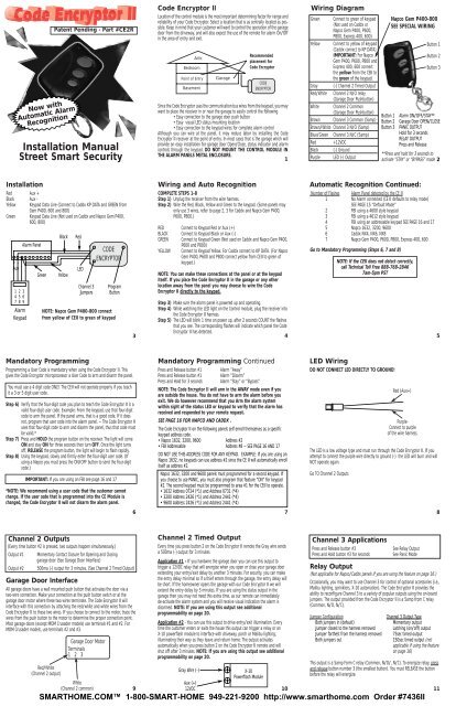
Wiring Diagram<br />
Green Connect to green of keypad<br />
(Not used on Caddx or<br />
Napco Gem P400, P600,<br />
P800, Express 400, 600)<br />
Yellow Connect to yellow of keypad<br />
(Caddx connect to KP DATA)<br />
IMPORTANT: For Napco<br />
Gem P400, P600, P800 and<br />
Express 400, 600 connect<br />
the yellow from the CEII to<br />
the green of the keypad.<br />
Gray (-) Channel 2 Timed Output<br />
Red/White Channel 2 N/O relay<br />
(Garage Door Pushbutton)<br />
White Channel 2 Common<br />
(Garage Door Pushbutton)<br />
Brown Channel 3 Common (5amp)<br />
Brown/White Channel 3 N/O (5amp)<br />
Blue/Green Channel 3 N/C (5amp)<br />
Red +12VDC<br />
Black (-) Ground<br />
Purple LED (-) Output<br />
Button 1<br />
Button 2<br />
Button 3<br />
Napco Gem P400-800<br />
SEE SPECIAL WIRING<br />
Button 1<br />
Button 2<br />
Button 3<br />
Alarm ON/OFF/STAY**<br />
Garage Door OPEN/CLOSE<br />
PANIC OUTPUT<br />
Hold for 3 seconds<br />
RELAY OUTPUT<br />
Press and Release<br />
**Press and hold for 3 seconds to<br />
activate “STAY” or “BYPASS” mode 2<br />
<strong>Installation</strong><br />
Red Aux +<br />
Black Aux -<br />
Yellow<br />
Keypad Data Line (Connect to Caddx KP DATA and GREEN from<br />
Gem P400, 600 and 800)<br />
Green Keypad Data Line (Not used on Caddx and Napco Gem P400,<br />
600, 800)<br />
+ -<br />
Aux<br />
1 2 3<br />
4 5 6<br />
7 8 9<br />
Alarm<br />
Keypad<br />
Alarm Panel<br />
Green<br />
Black<br />
Yellow<br />
Red<br />
LED<br />
Channel 3<br />
Jumpers<br />
CODE<br />
ENCRYPTOR<br />
Program<br />
Button<br />
NOTE: Napco Gem P400-800 connect<br />
from yellow of CEII to green of keypad<br />
Wiring and Auto Recognition<br />
COMPLETE STEPS 1-8<br />
Step 1) Unplug the receiver from the wire harness.<br />
Step 2) Wire the Red, Black, Yellow and Green to the keypad. (Some panels may<br />
only use 3 wires, refer to page 2, 3 for Caddx and Napco Gem P400,<br />
P600, P800.)<br />
RED Connect to Keypad Red or Aux (+)<br />
BLACK Connect to Keypad Black or Aux (-)<br />
GREEN Connect to Keypad Green (Not used on Caddx and Napco Gem P400,<br />
P600 and P800)<br />
YELLOW Connect to Keypad Yellow. For Caddx connect to KP DATA. (For Napco<br />
Gem P400, P600 and P800 connect yellow from CEII to green of<br />
keypad.)<br />
NOTE: You can make these connections at the panel or at the keypad<br />
itself. If you place the Code Encryptor II in the garage or any other<br />
location away from the panel you may choose to wire the Code<br />
Encryptor II directly to the keypad.<br />
Step 3) Make sure the alarm panel is powered up and operating.<br />
Step 4) While watching the LED light on the Control module, plug the receiver into<br />
the Code Encryptor II harness.<br />
Step 5) The LED will blink 1 time on power up, after 2 seconds COUNT the flashes<br />
that you see. The corresponding flashes will indicate which panel the Code<br />
Encryptor II has detected.<br />
3 4<br />
Automatic Recognition Continued:<br />
Number of Flashes Alarm Panel detected by the CE II<br />
1 No Alarm connected (CE II defaults to relay mode)<br />
SEE PAGE 15 “Default Mode”<br />
2 FBI using a 4600 style keypad<br />
3 FBI using a 4612 style keypad<br />
4 FBI using an addressable keypad SEE PAGE 16 and 17<br />
5 Napco 1632, 3200, 9600<br />
6 Caddx NX4, NX6, NX8<br />
7 Napco Gem P400, P600, P800, Express 400, 600<br />
Go to Mandatory Programming (Steps 6, 7 and 8)<br />
NOTE: If the CEII does not detect correctly,<br />
call Technical Toll Free 888-768-2846<br />
7am-5pm PST<br />
5<br />
Mandatory Programming<br />
Programming a User Code is mandatory when using the Code Encryptor II. This<br />
gives the Code Encryptor microprocessor a User Code to arm and disarm the panel.<br />
You must use a 4 digit code ONLY. The CEII will not operate properly if you teach<br />
it a 3 or 5 digit user code.<br />
Step 6) Verify that the four-digit code you plan to teach the Code Encryptor II is a<br />
valid four-digit user code. Example: From the keypad, use that four-digit<br />
code to arm the panel. If the panel arms, that is a good code. If it does<br />
not, program that user code into the alarm panel. – The Code Encryptor II<br />
uses that four-digit code to arm and disarm the panel, thus that code must<br />
be valid.*<br />
Step 7) Press and HOLD the program button on the receiver. The light will come<br />
ON and stay ON for three seconds then turn OFF. Once the light turns<br />
off, RELEASE the program button, the light will begin to flash rapidly.<br />
Step 8) Using the keypad, slowly and firmly enter the four-digit user code. (If<br />
using a Napco you must press the ON/OFF button to send the four-digit<br />
code.)<br />
IMPORTANT: If you are using an FBI see page 16 and 17<br />
*NOTE: We recommend using a user code that the customer cannot<br />
change. If the user code that is programmed into the CE Module is<br />
changed, the Code Encryptor II will not disarm the alarm panel.<br />
Mandatory Programming Continued<br />
Press and Release button #1 Alarm “Away”<br />
Press and Release button #1 Alarm “Disarm”<br />
Press and Hold for 3 seconds Alarm “Stay” or “Bypass”<br />
NOTE: The Code Encryptor II will arm in the AWAY mode even if you<br />
are outside the house. You do not have to arm the alarm before you<br />
exit. We do however recommend that you Arm the alarm system<br />
within sight of the status LED or keypad to verify that the alarm has<br />
received and responded to your remote request.<br />
SEE PAGE 16 FOR NAPCO AND CADDX .<br />
The Code Encryptor II on the following panels self enroll themselves as a specific<br />
keypad address code.<br />
• Napco 1632, 3200, 9600 Address #2<br />
• FBI Addressable Address #8 – SEE PAGE 16 AND 17<br />
DO NOT USE THIS ADDRESS CODE FOR ANY KEYPAD. EXAMPLE: If you are using an<br />
Napco 1632, no keypads can use address #2 since the CE II will automatically enroll<br />
itself as address #2.<br />
Napco 1632, 3200 and 9600 panels must programmed for a second keypad. If<br />
you choose to use PANIC, you must also program that feature “ON” for keypad<br />
#2. The second keypad must be programmed to area #1 for the CEII to operate.<br />
• 1632 Address 0724 (*1) and Address 0731 (*4)<br />
• 3200 Address 2426 (*1) and Address 2441 (*4)<br />
• 9600 Address 2426 (*1) and Address 2441 (*4)<br />
6 7<br />
LED Wiring<br />
DO NOT CONNECT LED DIRECTLY TO GROUND!<br />
The LED is a low voltage type and must run through the Code Encryptor II. If you<br />
attempt to connect the purple wire directly to ground (-) the LED will burn and will<br />
NOT operate again.<br />
Go TO Channel 2 Outputs<br />
Red (Aux+)<br />
Purple-<br />
Connect to purple<br />
of the wire harness.<br />
8<br />
Channel 2 Outputs<br />
(Every time button #2 is pressed, two outputs happen simultaneously.)<br />
Output #1<br />
Output #2<br />
Momentary Contact Closure for Opening and Closing<br />
garage door (See Garage Door Interface)<br />
500ma (-) output for 3 minutes, (See Channel 2 Timed Output)<br />
Garage Door Interface<br />
All garage doors have a wall mounted push button that activates the door via a<br />
two-wire connection. Make your connection at the push button switch or at the<br />
garage door motor where these two wires terminate. The Code Encryptor II will<br />
interface with this connection by attaching the red/white and white wires from the<br />
Code Encryptor II to these two wires. If you choose to connect to the motor, trace the<br />
wires from the push button to the motor to determine the proper connection point.<br />
Most garage doors (except MOM Crusader models) use terminals #1 and #2. For<br />
MOM Crusader models, use terminals #2 and #3.<br />
Red/White<br />
(Channel 2 output)<br />
Garage Door Motor<br />
Terminals<br />
1 2 3<br />
White<br />
(Channel 2 common)<br />
9<br />
Channel 2 Timed Output<br />
Every time you press button 2 on the Code Encryptor II remote the Gray wire sends<br />
a 500ma (-) output for 3 minutes.<br />
Application #1 - If you hardwire the garage door you can use this output to<br />
trigger a 12VDC relay that will energize when you open or close your garage door<br />
extending your entry/exit delay by another 3 minutes. For security, you can make<br />
the entry delay minimal so if a thief enters through the garage, the entry delay will<br />
be short. If the homeowner opens the garage with our Code Encryptor II we will<br />
extend the entry delay by 3 minutes. If you are using the status output in the<br />
garage then you may not need this extra time, as our remote can immediately<br />
de-activate the alarm system and you will receive visual indication the alarm is<br />
disarmed. NOTE: If you are using this output see additional<br />
programmability on page 20.<br />
Application #2 - You can use this output to drive entry/exit illumination. Every<br />
time the customer enters or exits the house this output can trigger a relay or an<br />
X-10 powerflash module to interface with driveway, porch or Malibu lighting,<br />
illuminating their way as they leave and return home. The output activates<br />
automatically when you press button 2 on the Code Encryptor II remote and will<br />
shut off after 3 minutes. NOTE: If you are using this output see additional<br />
programmability on page 20.<br />
Gray Wire (-)<br />
Aux (+)<br />
12VDC<br />
X-10<br />
Powerflash Module<br />
10<br />
Channel 3 Applications<br />
Press and Release button #3<br />
Press and Hold button #3 for seconds<br />
See Relay Output<br />
See Panic Mode<br />
Relay Output<br />
(Not applicable for Napco/Caddx panels if you are using the feature on page 16.)<br />
Occasionally, you may want to use Channel 3 for control of optional accessories (i.e.,<br />
Malibu lighting, sprinklers, X-10 automation). The Code Encryptor II provides the<br />
ability to reconfigure Channel 3 to a variety of popular outputs using the on-board<br />
jumpers. The output provided from the Code Encryptor II is a 5amp from C relay<br />
(Common, N/O, N/C).<br />
Jumper Configuration<br />
Both jumpers in (default)<br />
Jumper closest to the harness removed<br />
Jumper farthest from the harness removed<br />
Both jumpers out<br />
Channel 3 Output Type<br />
Momentary output<br />
Latching (on/off) output<br />
75sec timed output<br />
150sec timed output (not<br />
applicable if using the feature<br />
on page 16)<br />
This output is a 5amp Form C relay (Common, N/O/, N/C). To energize relay, press<br />
and release button number 3 (the smallest button). You must RELEASE the button<br />
before the relay will energize.<br />
11
Panic Mode<br />
Press and hold button 3 on the remote control for at least 3 seconds. This will cause<br />
the panel to go into a panic mode. Press button 1 (largest button) to disarm the panel.<br />
Napco 1632, 3200 and 9600 panels must be programmed for keypad #2 panic<br />
“ON” . SEEPAGE 7 for the Napco Program Guide.<br />
If you are using a panel that does not have a default setting for keypad panic you<br />
must program that option “ON” before our system will operate. Most manufacturers<br />
set the keypad Panic as a default setting.<br />
DEACTIVATING THE PANIC FEATURE:<br />
In the event the user does not want to access a panic button through the remote<br />
control, it can be de-activated from the Code Encryptor II’s memory.<br />
Step 1) Unplug the wire harness from the Code Encryptor II.<br />
Step 2) Press and HOLDthe program button.<br />
Step 3) While HOLDINGthe program button, plug the Code Encryptor II harness<br />
back in. The LED light located on the front will turn ON.<br />
Step 4) Wait until the light turns “OFF”.<br />
Step 5) Once the light has turned “OFF” release the button<br />
Panic Continued<br />
ACTIVATING THE PANIC MODE<br />
NOTE: This is the default setting of the Code Encryptor II.<br />
If you have previously programmed remote panic “OFF” and would like to turn it<br />
back “ON” follow the steps below. If this is a NEW installation Panic “ON” is the<br />
DEFAULT setting for the Code Encryptor II.<br />
Step 1) Unplug the wire harness from the Code Encryptor II.<br />
Step 2) Press and HOLDthe program button.<br />
Step3) While HOLDING the program button, plug the Code Encryptor II harness<br />
back in. The LED light located on the front will turn ON.<br />
Step 4) Immediately release the program button.<br />
IF NECESSARY, PROGRAM THE ALARM PANEL FOR KEYPAD PANIC.<br />
To Add or Delete Remotes<br />
TO ADD A NEW REMOTE<br />
METHOD #1<br />
To add a remote to your Code Encryptor II, disarm the panel and Enter 78738,<br />
(if using a Napco 1632, 3200 or 9600 press the ON/OFF to send the data.) from<br />
the keypad. The system will arm in the “STAY” mode. Press and release button #1<br />
(largest button on the remote control) until the arm system disarms. It should take a<br />
total of four presses.<br />
METHOD#2<br />
To add a remote to your Code Encryptor II PRESSANDRELEASEthe program<br />
button on the receiver. The light on the receiver will come ON. Immediately PRESS<br />
button 1 (largest button) on the new remote control THREETIMES. The light on<br />
the receiver should go OFF, indicating the remote has been learned. If the light on<br />
the receiver stays ON, the remote has not been learned. Remove and replace the<br />
harness, wait 15 seconds while auto recognition occurs and follow these instructions<br />
again.<br />
The Code Encryptor II can hold up to seven remotes.<br />
12<br />
13 14<br />
DEFAULT MODE:<br />
• If the Code Encryptor II fails to recognize any of the data coming from the keypad<br />
wires, it will automatically default to a relay mode for button #1<br />
• If this happens, verify that you are properly wired to one of the alarms listed on<br />
page 5.<br />
• If you have connected the CE II to an alarm it does not recognize, follow the<br />
wiring below for a keyswitch mode.<br />
• Program a selected zone as “Keyswitch Arming.”<br />
• Do not use the green or yellow wires.<br />
<strong>Installation</strong> for Keyswitch Arming<br />
Red Aux +<br />
Black Aux -<br />
Brown/White Zone programmed for keyswitch arming<br />
Brown Common adjacent to zone<br />
Alarm Panel<br />
Zone programmed<br />
for keyswitch arming<br />
Resistor should be in-line OR across<br />
the zone, whichever clears the zone.<br />
Black<br />
Red<br />
Brown<br />
CODE<br />
ENCRYPTOR<br />
Brown/White<br />
15<br />
Napco/Caddx Panels<br />
• If a zone is programmed for “HOME/AWAY BYPASS” or AUTO-BYPASS”, the alarm<br />
will bypass that zone unless as “ENTRY/EXIT” zone is tripped after arming.<br />
• If you wish to have a zone programmed as mentioned above, the CEII can be<br />
installed to allow you to arm the panel in the “AWAY” mode from outside the house.<br />
Step 1)Remove BOTH jumpers from the CEII control module. They are located<br />
next to the wire harness<br />
Step 2)Connect the Channel 3 wires to the zone programmed for “ENTRY/EXIT”.<br />
When armed with the CEII remote, the relay will energize for 1 second,<br />
causing the zone to be tripped and arm the alarm in the “AWAY” mode.<br />
Zone programmed<br />
as an entry/exit<br />
Alarm Panel<br />
Black<br />
CODE<br />
ENCRYPTOR<br />
• When using an addressable keypad like an XK-7LC, XK-5LC, XK-508, XK-512, XK-<br />
516, XK-708, XK-716 you may have to complete an extra step before the CEII will<br />
operate. SEEPAGE17.<br />
16<br />
Red<br />
Brown<br />
Brown/White<br />
Channel 3 wires offer N/O and N/C contacts.<br />
Utilize the wires to open or close the zone based on your installation.<br />
FBI Addressable Keypads<br />
FBI Addressable Continued<br />
• These FBI panels poll for addressable or non addressable keypads upon power up<br />
OR after you exit programming. Since the CEII requires that you plug it in after the<br />
FBI is powered up, it misses that polling loop.<br />
TO have the FBI panel Re-Poll for keypads and CEII units<br />
Step 1)Enter Programming Mode: Press “CODE” + ”*” and installers code (2468<br />
default) followed by a “1”.<br />
Step 2)Exit Programming by pressing the “STAY” key.<br />
Step 3)The CEII will enroll itself as an Addressable Keypad at address #8<br />
To Delete ALL Remotes<br />
METHOD #1<br />
To delete a lost or stolen remote from the Code Encryptor II, you must purge the<br />
entire memory. This will delete all of the current remotes. You will then have to add<br />
them back in one at a time. To purge the memory, disarm the panel. Enter<br />
76278,(if using a Napco 1632, 3200 or 9600 press the ON/OFF to send the<br />
data), from the keypad. The keypad on most panels will “beep” or the lights will<br />
turn off momentarily to confirm delete. Follow the instructions on page 14 (To Add<br />
a New Remote).<br />
METHOD#2<br />
To delete a lost or stolen remote from the Code Encryptor II, you must purge the<br />
entire memory. This will delete all of the current remotes. You will then have to add<br />
them back into memory. To purge, PRESS AND HOLDthe program button, the<br />
light will come ON for four seconds, then go OFF, and finally it will come ON again,<br />
indicating that all the remotes in memory have been purged. Release the program<br />
button and follow the instructions on page 14 (To Add a New Remote). 17<br />
Troubleshooting<br />
PROBLEM: I press Button #1 (largest, button) but nothing happens.<br />
SOLUTION: 1)Did you teach the Code Encryptor II a VALID four-digit user code?<br />
Note: The code you teach the Code Encryptor II must be a master<br />
code or one of the current user codes.<br />
2)Press button #2 (middle button), if you do NOT hear a “click” at<br />
the receiver, GOTO PAGE14 and learn that remote into the Code<br />
Encryptor II.<br />
PROBLEM: I press and hold button #3 (smallest button) and I do not get a panic.<br />
SOLUTION: 1)Did you program the panel for keypad panic?<br />
2)To program the Code Encryptor II for panic GO TO PAGE 13.<br />
PROBLEM: Unit does not seem to identify the panel I am using.<br />
SOLUTION: Call technical 888-768-2846.<br />
PROBLEM: I am using an FBI panel but the system won’t operate.<br />
SOLUTION: 1) Verify that NOKEYPADS are set to address #8.<br />
2) Enter and exit programming to have the panel poll for keypads or<br />
a CEII unit. (SEEPAGE 16 and 17)<br />
PROBLEM: I an using a Napco 1632, 3200 or 9600 and the remote will not<br />
arm or disarm.<br />
SOLUTION: 1)Verify the NO KEYPADS are set to address #2<br />
2)Did you program Keypad #2 to Area #1 (SEEPAGE7)<br />
18<br />
Specifications<br />
RECEIVER<br />
• 12VDC Power Input<br />
• Channels 1 Data outputs<br />
• Channel 2 Relay N/O, Comm (10amp)<br />
• Channel 3 selectable: Form C Relay (N/O, N/C, Comm) 5amp<br />
This output can be reconfigured from a pulsed output to a latching, 75 second<br />
timed or 150 second timed output.<br />
• Channel 3 - Keypad panic data output (Programmable On or OFF)<br />
Frequency 303Mhz<br />
Stand by Power Consumption 15ma<br />
Temperature Range-5°F to 160°F (Indoor use only)<br />
REMOTE CONTROL<br />
Battery12VDC Mini (Part #GP23A) Replace battery at least once a year.<br />
Range150+ feet<br />
CHANNEL3 OUTPUT<br />
Both jumpers in (default)<br />
Momentary output<br />
Jumper closest to the harness removed Latching (on/off) output<br />
Jumper farthest from the harness removed<br />
Both jumpers out<br />
75sec timed output<br />
150sec timed output (not<br />
applicable if using the feature<br />
on page 16)<br />
Optional Reversible Outputs<br />
Channel 2 has two independent outputs that occur when button #2 is pressed. The<br />
first output is a momentary relay contact closure which is intended for the use of<br />
opening and closing a garage door. This is the primary output and can not be<br />
changed or reconfigured. The second output is a (-) 500ma transistor output to<br />
provide a zone bypass or illuminated entry/exit.<br />
• If you are not using the relay for Channel 3 you may choose to swap the<br />
(-) transistor output for the relay. In this instance you will then have two contact<br />
closures every time Button # 2 is pressed. The standard momentary contact<br />
closure and ALSO a Form C relay that will energize automatically for 3 minutes<br />
every time the garage door is opened or closed.<br />
To Swap the transistor and relay outputs.<br />
Step 1) While watching the LED on the CE II receiver press and HOLD button 1 and<br />
3 simultaneously on the remote control until the LED on the CE II receiver<br />
illuminates. (approx. 5 seconds)<br />
Step 2) To make channel 2 a relay press the program button on the CE II Receiver<br />
TWICE, to make it a transistor output press ONCE (Default setting)<br />
Step 3) Wait 10 seconds and the CE II will automatically reconfigure the outputs.<br />
NOTE- Even if you swap outputs, the Panic button will still operate if<br />
you press and HOLD button #3 for three seconds.<br />
IMPORTANT<br />
STREET SMART SECURITY TECHNICAL CAN BE REACHED AT:<br />
This feature will not work for NAPCO/CADDX<br />
12925 Brook Printer Place, Suite 410, Poway, CA 92064<br />
if you are using the feature on page 16.<br />
M-F 7AM-5PM PST AT (888) 768-2846 OR (619) 513-9352-FAX<br />
19<br />
20<br />
.<br />
21<br />
Federal Communications Commission<br />
(FCC) Statement<br />
This equipment has been tested to FCC requirements and has been found acceptable for use.<br />
The FCC requires the following statement for your information:<br />
This equipment generates and uses radio frequency energy and if not installed and used<br />
properly, that is, in strict accordance with the manufacturer's instructions, may cause interference<br />
to radio and television reception. It has been type tested and found to comply with the<br />
limits for a Class B computing device in accordance with the specifications in Part 15 of FCC<br />
Rules, which are designed to provide reasonable protection against such interference in a residential<br />
installation. However, there is no guarantee that interference will not occur in a particular<br />
installation. If this equipment does cause interferences to radio or television reception ,<br />
which can be determined by turning the equipment off and on, the user is encouraged to try to<br />
correct the interference by one or more of the following measures:<br />
• If using an indoor antenna, have a quality outdoor antenna installed.<br />
• Reorient the receiving antenna until interference is reduced or eliminated<br />
• Move the receiver away from the control/communicator.<br />
• Move the antenna leads away from any wire runs to the control/communicator.<br />
• Plug the control/communicator into a different outlet so that it and the receiver are on<br />
different branch circuits.<br />
If necessary, the user should consult the dealer or an experienced radio/television<br />
technician for additional suggestions.<br />
The user or installer may find the following booklets prepared by the Federal<br />
Communications Commission helpful: “Interference Handbook”<br />
This booklet is available from the U.S. Government Printing Office, Washington, DC 20402.<br />
The user shall not make any changes or modifications to the equipment unless authorized by<br />
the installation instructions or User’s <strong>Manual</strong>. Unauthorized changes or modifications could<br />
void the user’s authority to operate the equipment.<br />
Canadian Department of<br />
Communications (DOC) Statement<br />
NOTICE: The Canadian Department of Communications label identifies certified<br />
equipment. This certification means that the equipment meets certain<br />
telecommunications network protective, operational and safety requirements. The<br />
Department does not guarantee the equipment will operate to the user's satisfaction .<br />
Before installing this equipment, users should ensure that it is permissible to be<br />
connected to the facilities of the local telecommunications company. The equipment<br />
must also be installed using an acceptable method of connection. In some cases, the<br />
company's inside wiring associated with a single line individual service may be<br />
extended by means of certified connector assembly (telephone extension cord). The<br />
customer should be aware that compliance with the above conditions may not prevent<br />
degradation of service in some situations.<br />
Repairs to certified equipment should be made by an authorized Canadian<br />
maintenance facility designed by the supplier. Any repairs or alterations made by the<br />
user to this equipment, or equipment malfunctions, may give the telecommunications<br />
company cause to request the user to disconnect the equipment.<br />
Users should ensure for their own protection that the electrical ground connections<br />
of the power utility, telephone lines and internal metallic water pipe system, if present,<br />
are connected together. This precaution may be particularly important to rural<br />
areas.<br />
CAUTION: User should not attempt to make such connections themselves, but should<br />
contact the appropriate electric inspection authority, or electrician, as appropriate.<br />
The Load Number (LN) assigned to each terminal device denotes he percentage of<br />
the total load to be connected to a telephone loop which is used by the device, to<br />
prevent overloading. The termination on a loop may consist of any combination of<br />
devices subject only to the requirement that the total of the Load Numbers of all the<br />
devices does not exceed 100.<br />
22 23


