INSTRUCTION MANUAL - Philippi
INSTRUCTION MANUAL - Philippi
INSTRUCTION MANUAL - Philippi

Create successful ePaper yourself
Turn your PDF publications into a flip-book with our unique Google optimized e-Paper software.
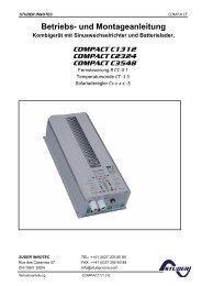
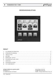
k POWER DISTRIBUTION PANELS SERIES 200<br />
<strong>INSTRUCTION</strong> <strong>MANUAL</strong><br />
Introduction<br />
The power distribution panels series 200 are designed for the distribution and protecting<br />
of the electrical 12/24V DC system. At the front panel there are circuit breakers, control<br />
switches, monitoring displays and sockets (depending on type).<br />
Each circuit is switched and protected by a thermical circuit breaker with rocker switch.<br />
It`s integrated light diode is showing the circuit status. In case of a short, the breaker<br />
switches automatically off and the light goes off.<br />
Some models are equipped with additional battery voltage meters and/or tank gauges.<br />
The additional current meters inform about the actual flowing discharge current.<br />
Each panel comes with a set of self-adhesive labels, which can be placed at each circuit<br />
breaker on the signed fields .<br />
The circuit breakers/switches are suitable for battery voltages of 12V and/or 24V without<br />
modification.<br />
philippi elektrische systeme gmbh<br />
www. philippi-online.de<br />
Neckaraue 19<br />
info@philippi-online.de<br />
D-71686 Remseck am Neckar Telefon: +49 (0)7146/8744-0, Fax -22
k POWER DISTRIBUTION PANELS SERIES 200<br />
SAFETY REFERENCES<br />
• unautorised change to the equipment will invalidate the CE sign<br />
• the connection of the distribution circuits may be made only by electrical specialists.<br />
• before connecting the distribution circuits the battery terminals must be clamped.<br />
• Important! Pay attention to the correct polarity of the batteries!<br />
• the automatic circuit breakers are securing the wiring for the consumers. The security of the<br />
attached consumers has to be done via the built-in safety devices.<br />
The assembly and operating instruction is a component of the STV package.<br />
It must be kept (for reference).<br />
Importantly: - for later maintenance work - and for the use of subsequent owners of<br />
the equipment.<br />
EXCLUSION OF LIABILITY<br />
Both the adherence to the operating instruction, and the conditions and methods during installation,<br />
using and maintenance of the distribution panel cannot be supervised by philippi electrical<br />
systems. Therefore we do not take any responsibility for loss, damage or costs, which develop<br />
due to incorrect installation and/or inappropriate enterprise.<br />
WARRANTY<br />
philippi elektrische systeme gmbh grants a two year limited and not transferable warranty for the<br />
first buyer of this equipment, carried out due to our "general trading conditions".<br />
These trading conditions are basis of all sales and delivery offers, they are printed and attached<br />
to all offers and confirmation of orders in our catalogues.<br />
CE-CONFORMITY<br />
CONTENT<br />
This product fulfills the requirements of the European Regulation:<br />
2004/108/EG “electromagnetic compatibility”<br />
Following harmonised standards were implemented::<br />
Immunität: EN 61000-6-1:2007<br />
Emission: EN 61000-6-3:2007<br />
The conformity of the equipment is confirmed by the CE mark.<br />
Power distribution panel<br />
This manual<br />
1 set of self adhesive labels SKZ
k POWER DISTRIBUTION PANELS SERIES 200<br />
ACCESSORIES (TO BE ORDERED SEPARATELY)<br />
Self adhesive labels (1set)<br />
SKZ-D, SKZ-GB, SKZ-NL, SKZ-FR, SKZ-ES, SKZ-DK<br />
SKZ-Mobil (Automobile)<br />
Stack connectors 6,3mm -2,5mm2 2 FSH 6,3/1,5-2,5<br />
Circuit breaker 1-pole<br />
3130-F11B-H7T1-W29AG-10A (6..20A)<br />
Circuit breaker 2-poles<br />
3130-F15B-H7T1-W29AG-10A (6..16A)<br />
TECHNICAL DATA<br />
Dimensions<br />
see cataloge<br />
Rated voltage DC 10-28V<br />
Fuse size<br />
10 A (Standard), alt.: 6, 16, 20 A (20A only 1-pole)<br />
Panel<br />
Aluminium grey coated<br />
INSTALLATION<br />
Well accessible places inside the boat are suitable for the assembly; usually at the chart table.<br />
The rear area should have at least a depth of 15 cm, in order to be able to implement the<br />
wiring carefully and clearly and thus surely.<br />
It`s a good advise to install the panel in such a way that it is accessible for extensions, changes<br />
and subsequent repairs from the rear side.<br />
For the installation a cutout of 10mm smaller per side of the instrument panel dimensions is<br />
to be planned. The instrument panel can be fastened with screws of your choice by using the<br />
four (six) mounting holes.<br />
WARNING<br />
High currents can cause overheating of the wiring or connections due to too thin lines or<br />
transition resistance by corroded contacts. Overheating can cause fire!<br />
Consider therefore the printed cable diameter table and pay attention to safe and firm<br />
connection.<br />
CONNECTION<br />
the pre-wired red inlet cables (+) 6mm2 have to be attached to the positive terminal of the<br />
service battery. When extending the inlet-line installed at the distribution circuit the diameter of<br />
the extension cable may not be smaller - risk of fire!<br />
The inlet must be attached at the battery over an inserted high current safety device<br />
dimensioned correctly to the inlet cross section.<br />
The consumer outlet lines have to be attached or screwed at the stack- or screwing contacts of<br />
the automatic circuit breakers.<br />
The black negative conductor (-) has to be attached to the negative pole of the battery. It serves<br />
the integrated LEDs and other eventually integrated electronic devices such as voltmeter,<br />
digital displays and position light monitoring.<br />
OVERLOAD<br />
in the case of overloading or short-circuit of an electric circuit the connected consumers are<br />
switched off by the integrated circuit breaker and the light-emitting diode display expires.<br />
After the overloading or short-circuit condition is suspended the respective automatic circuit can<br />
be used again by re-switching.
k POWER DISTRIBUTION PANELS SERIES 200<br />
Connection to the battery<br />
Fuse size max. 35A for 6 mm²- wire<br />
Fuse size max. 50A for 10 mm²- wire<br />
Panel<br />
Battery<br />
Consumer 1<br />
Consumer 2<br />
Consumer 3<br />
Consumer 4<br />
Consumer 5<br />
Minus-<br />
Busbar<br />
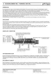
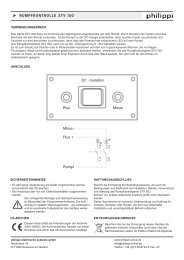
Connection of the instruments<br />
- : minus battery<br />
+ : power supply 12/24V<br />
B : illumination 12/24V<br />
S : tank sensor inlet (10 - 180 Ohm)<br />
TGT / TGW / UTN
k POWER DISTRIBUTION PANELS SERIES 200<br />
Connection of the position light monitor POS6E<br />
Bowlantern Port<br />
Bowlantern Stb<br />
Stern light<br />
Anchor light<br />
Tricolour light<br />
J 1<br />
Steaming light<br />
Minus<br />
Wire cross section:<br />
of the connection of the position lights: 2,5 mm² (normal bulbs), min.1mm²<br />
for LED-navigation lights.<br />
Bowlantern:<br />
If you`re using a twocolour - bowlantern, you have to connect it to outlet A1<br />
and the jumper has to remain (delivery status).<br />
If there are two separate position lights (port/starboard), you have to remove<br />
the jumper J1.<br />
Connection of the control switches<br />
Needed switches:<br />
Voltmeter-switch-over: 1-0-2 Ord.no. 5 1808 1103<br />
Tanksensor-switch-over: 1-2 Ord.no. 5 1803 1102<br />
Illumination switch: 0-1 Ord.no. 5 1801 1102<br />
Batt.-main switch FBH: (1)-0-(2) Ord.no. 5 1808 1302<br />
Bilge Auto-Man.switch: 1-0-2 Ord.no. 5 1808 1103
k POWER DISTRIBUTION PANELS SERIES 200<br />
Connection of the instruments<br />
view is from the rear side of the panel<br />
switch for the<br />
instrument`s illumination<br />
tank meter<br />
connection of the sensor<br />
switch off<br />
alternative<br />
circuit breaker<br />
connection<br />
circuit<br />
instrument lights<br />
or<br />
over fuse 1A<br />
at circuit breakers busbar<br />
circuit<br />
tank instruments<br />
tank sensor TG<br />
voltmeter:<br />
voltmeter with switch-over<br />
for measuring lines<br />
tank instrument:<br />
switch over<br />
for 2 sensors<br />
switch over 1-0-2<br />
switch over 1-0-2<br />
battery 1<br />
connection<br />
breaker<br />
for tank instruments<br />
battery 2 sensor 1 sensor 2<br />
please fuse measuring lines<br />
directly at the battery !
k POWER DISTRIBUTION PANELS SERIES 200<br />
Further connection examples for control switches<br />
switch for<br />
remote battery main<br />
switch FBH<br />
AUTO-MANswitch<br />
over for<br />
automatic bilge pump<br />
change-over<br />
push button (1)-0-(2)<br />
switch over<br />
1-0-2<br />
circuit breaker<br />
bilge pump switch<br />
circuit bilge pump<br />
bilge pump<br />
battery<br />
The tank monitor TCM can also be switched on/off by using a control switch.<br />
Also the display lighting of the BCM/TCM monitors can be switched by them.<br />
Please pay attention, that the supply wires are fused!<br />
Table of cable diameters<br />
Single conductor refering to „Germanischer Lloyd“<br />
Conductor-Cross<br />
Recommended circuit<br />
SectionArea Current rating breaker rating<br />
mm 2 A A<br />
1,5 12 10<br />
2,5 17 16<br />
4 23 20<br />
6 29 25<br />
10 40 35<br />
16 54 50
k POWER DISTRIBUTION PANELS SERIES 200<br />
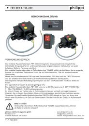
Connection of the ammeter and the TSA<br />
Ammeter with integrated shunt<br />
Ammeter with external shunt<br />
+<br />
inlet<br />
ammeter<br />
+<br />
outlet<br />
ammeter<br />
busbar<br />
shunt<br />
battery<br />
circuit breaker<br />
(rear side)<br />
battery<br />
circuit breaker<br />
Remote control for deep discharge<br />
protection TSA<br />
rd<br />
bl<br />
push button 0 - (1)<br />
ord.no. 5 1801 1202<br />
deep discharge protection<br />
TSA