

EL280UH Two-Stage Gas Furnace Installation Manual - Lennox
EL280UH Two-Stage Gas Furnace Installation Manual - Lennox
EL280UH Two-Stage Gas Furnace Installation Manual - Lennox

You also want an ePaper? Increase the reach of your titles
YUMPU automatically turns print PDFs into web optimized ePapers that Google loves.
Cleaning the Heat Exchanger and Burners<br />
NOTE − Use papers or protective covering in front of the furnace<br />
during cleaning.<br />
1 − Turn off both electrical and gas power supplies to furnace.<br />
2 − Remove flue pipe and top cap (some applications top<br />
cap can remain) from the unit.<br />
3 − Label the wires from gas valve, rollout switches, primary<br />
limit switch and make−up box then disconnect them.<br />
4 − Remove the screws that secure the combustion air inducer/pressure<br />
switch assembly to the collector box.<br />
Carefully remove the combustion air inducer to avoid<br />
damaging blower gasket. If gasket is damaged, it must<br />
be replaced to prevent leakage.<br />
5 − Remove the collector box located behind the combustion<br />
air inducer. Be careful with the collector box gasket.<br />
If the gasket is damaged, it must be replaced to<br />
prevent leakage.<br />
6 − Disconnect gas supply piping. Remove the screw securing<br />
the burner box cover and remove cover. Remove<br />
the four screws securing the burner manifold assembly<br />
to the vestibule panel and remove the<br />
assembly from the unit.<br />
7 − Remove screws securing burner box and remove<br />
burner box.<br />
8 − NOX units only − Remove screw securing NOX insert.<br />
Remove NOX insert. See figure 37.<br />
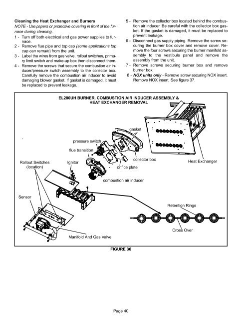
<strong>EL280UH</strong> BURNER, COMBUSTION AIR INDUCER ASSEMBLY &<br />
HEAT EXCHANGER REMOVAL<br />
gasket<br />
pressure switch<br />
flue transition<br />
Rollout Switches<br />
(location)<br />
Ignitor<br />
orifice plate<br />
collector box<br />
Heat Exchanger<br />
combustion air inducer<br />
Sensor<br />
Retention Rings<br />
Manifold And <strong>Gas</strong> Valve<br />
Cross Over<br />
FIGURE 36<br />
Page 40


