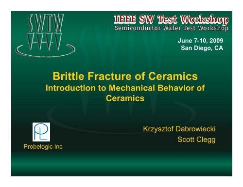
Brittle Fracture of Ceramics - Semiconductor Wafer Test Workshop
Brittle Fracture of Ceramics - Semiconductor Wafer Test Workshop
Brittle Fracture of Ceramics - Semiconductor Wafer Test Workshop

You also want an ePaper? Increase the reach of your titles
YUMPU automatically turns print PDFs into web optimized ePapers that Google loves.
June 7-10, 2009<br />
San Diego, CA<br />
<strong>Brittle</strong> <strong>Fracture</strong> <strong>of</strong> <strong>Ceramics</strong><br />
Introduction to Mechanical Behavior <strong>of</strong><br />
<strong>Ceramics</strong><br />
Probelogic Inc<br />
Krzyszt<strong>of</strong> Dabrowiecki<br />
Scott Clegg
OUTLINE<br />
– Sources <strong>of</strong> ceramic fracture in the vertical probe cards<br />
– Introduction to theory <strong>of</strong> ceramic fracture<br />
– 3-point flexural strength test <strong>of</strong> ceramics<br />
– Finite element model <strong>of</strong> ceramic specimen<br />
– Ceramic stress intensity factor (SIF)<br />
– Conclusion<br />
June 7 to 10, 2009<br />
IEEE SW <strong>Test</strong> <strong>Workshop</strong> 2
Ceramic <strong>Fracture</strong>s in Vertical Probe Cards<br />
The major sources <strong>of</strong> ceramic fractures in the<br />
vertical standard probe card processes:<br />
A. Inherent material properties<br />
Crack<br />
Cracks<br />
B. Ceramic machining –preparing <strong>of</strong> the<br />
ceramic parts:<br />
- Grinding<br />
- Cutting<br />
- Drilling<br />
- Lapping<br />
C. Using ceramics as a part <strong>of</strong> probe card:<br />
- Assembly Process (tightening LD<br />
screws, accidentally dropping part)<br />
- <strong>Wafer</strong> Probing (OT wafers, high<br />
probe current, high temperature test)<br />
- Probe Cleaning (dragging probes at<br />
high OT over cleaning pads)<br />
June 7 to 10, 2009<br />
IEEE SW <strong>Test</strong> <strong>Workshop</strong> 3
Classical Model <strong>of</strong> the <strong>Fracture</strong> Mechanics<br />
Stress Intensity Factor KIC:<br />
f<br />
h<br />
C=1.12 for edge flaws<br />
KIC – MPa em<br />
r<br />
2a<br />
t<br />
t<br />
t<br />
L<br />
Stress Flaw Tip Concentration:<br />
b<br />
f<br />
Flaw tip stress<br />
concentration<br />
Where: o > 0 and o
Flexural Strength <strong>Test</strong><br />
- Define and compare flexural strength <strong>of</strong> the ceramics<br />
- Evaluate flaw size in the cross-section<br />
- Correlate fracture toughness with flaw size<br />
- Correlate strength received from tests with FE models<br />
June 7 to 10, 2009<br />
IEEE SW <strong>Test</strong> <strong>Workshop</strong> 5
Three Point Bending Model<br />
Max tensile stress<br />
Force<br />
Ceramic specimen<br />
b<br />
h<br />
L<br />
Stress <strong>of</strong> Rupture (Flexural Strength, Modulus <strong>of</strong> Rupture)<br />
Where: F- force<br />
June 7 to 10, 2009<br />
L- distance between supports<br />
b – specimen width<br />
h – specimen thickness<br />
IEEE SW <strong>Test</strong> <strong>Workshop</strong> 6
<strong>Test</strong> Description<br />
Contact Tip Size<br />
Fixture Model<br />
Force direction<br />
Ls<br />
In the ceramic flexural strength<br />
studies have been used four<br />
materials: macor, alumina, zircon<br />
and silicon nitride. The<br />
mechanical properties <strong>of</strong><br />
ceramics are listed in table 1.<br />
Five to twelve specimens for each<br />
material were prepared with<br />
dimensions: length=0.500”,<br />
width= 0.145”, thickness= 0.010”<br />
The bending tests were<br />
conducted with the span length <strong>of</strong><br />
0.300”. All tests were carried out<br />
in an ambient temperature.<br />
The load-force at the fracture time<br />
has been recorded.<br />
June 7 to 10, 2009<br />
IEEE SW <strong>Test</strong> <strong>Workshop</strong> 7
<strong>Test</strong> Notes and Observations<br />
- No initial cracks or preexisting large flaws on the specimens<br />
- All specimens under the load- force spontaneously and rapidly<br />
fractured without any signs <strong>of</strong> warning, some <strong>of</strong> them cracked<br />
intermittently after 3-5 minutes<br />
- No dents or plastic deformations on the ceramic surfaces have<br />
been observed in the area <strong>of</strong> contact force<br />
- Most <strong>of</strong> ceramic fractures occurred in the area <strong>of</strong> high stresses, in<br />
the middle <strong>of</strong> specimen<br />
Table 1. Mechanical Properties<br />
Properties <strong>of</strong><br />
materials<br />
Macor<br />
Alumina<br />
Silicon<br />
Nitride<br />
Zircon<br />
Density (r)<br />
g/cm 3<br />
2.52<br />
3.23<br />
3.92<br />
4.2<br />
Young's modulus (E)<br />
(GPa)<br />
66.9<br />
380<br />
320<br />
175<br />
Poison's ratio ()<br />
0.29<br />
0.24<br />
0.28<br />
0.4<br />
Coefficient <strong>of</strong> Thermal<br />
Expansion<br />
June 7 to 10, 2009<br />
x10 -6 /C<br />
9.7<br />
8.2<br />
3.2<br />
IEEE SW <strong>Test</strong> <strong>Workshop</strong> 8<br />
4.2
Images <strong>of</strong> <strong>Fracture</strong>d Specimens<br />
MACOR<br />
ALUMINA<br />
ZIRCON<br />
SILICON NITRIDE<br />
June 7 to 10, 2009<br />
IEEE SW <strong>Test</strong> <strong>Workshop</strong> 9
SEM Pictures <strong>of</strong> Cross-Sections<br />
MACOR<br />
ALUMINA<br />
ZIRCON<br />
SILICON NITRIDE<br />
June 7 to 10, 2009<br />
IEEE SW <strong>Test</strong> <strong>Workshop</strong> 10
Weibull Analysis<br />
The fracture strength distributions <strong>of</strong> test readings have been shown in<br />
Weibull probabilistic plots. The cumulative probability was calculated<br />
using the median rank method. The strength distribution <strong>of</strong> tested<br />
materials shows a straight line calculated based on shown equation<br />
below. Two calculated Weibull parameters, scale and shape, are<br />
shown in table 2<br />
Table 2 Weibull parameters<br />
Material MACOR ALUMINA ZIRCON SILICON NITRIDE<br />
Scale parameter s[MPa] 241.4 613.3 694.9 1352.0<br />
Shape parameter m [MPa] 6.1 12.4 25.4 6.7<br />
June 7 to 10, 2009<br />
IEEE SW <strong>Test</strong> <strong>Workshop</strong> 12
Distribution <strong>of</strong> <strong>Fracture</strong> Strength<br />
Cumulative Probability F( sf)<br />
1.00<br />
0.90<br />
0.80<br />
0.70<br />
0.60<br />
0.50<br />
0.40<br />
0.30<br />
0.20<br />
0.10<br />
MACOR<br />
Max 275.80<br />
Min 183.97<br />
Range 91.83<br />
Mean 224.10<br />
Std Dev 37.18<br />
ALUMINA<br />
Max 656.27<br />
Min 528.76<br />
Range 127.51<br />
Mean 590.00<br />
Std Dev 49.61<br />
ZIRCON<br />
Max 721.04<br />
Min 648.93<br />
Range 72.10<br />
Mean 682.10<br />
Std Dev 27.15<br />
SILICON NITRIDE<br />
Max 1598.73<br />
Min 1047.22<br />
Range 551.51<br />
Mean 1253.41<br />
Std Dev 205.23<br />
Macor<br />
Alumina<br />
Zircon<br />
SN<br />
Linear (Macor)<br />
Linear (Alumina)<br />
Linear (Zircon)<br />
Linear (SN)<br />
0.00<br />
0 100 200 300 400 500 600 700 800 900 1000 1100 1200 1300 1400 1500 1600 1700<br />
<strong>Fracture</strong> Strength sf [ MPa]<br />
June 7 to 10, 2009<br />
IEEE SW <strong>Test</strong> <strong>Workshop</strong> 13
FE 3-D Bending Fixture Model<br />
FE Model<br />
<strong>Fracture</strong> force = 2.57 lbs<br />
Max Stress at contact point = 586 MPa<br />
Max displacement = 0.00092 in<br />
The calculation discrepancy:<br />
=[(mean – ansys mean ]x100%= 0.67%<br />
Alumina Stress Distribution<br />
Alumina Displacement<br />
June 7 to 10, 2009<br />
IEEE SW <strong>Test</strong> <strong>Workshop</strong> 14
Macor Fractographic Observation<br />
Flaw size = 50 m, KI= 1.8 MPa em<br />
June 7 to 10, 2009<br />
IEEE SW <strong>Test</strong> <strong>Workshop</strong> 15
Alumina Fractographic Observation<br />
Flaw size = 25 m; KI= 3.7 MPa em<br />
June 7 to 10, 2009<br />
IEEE SW <strong>Test</strong> <strong>Workshop</strong> 16
Zircon Fractographic Observation<br />
Flaw size = 25 m; KI= 4.6 MPa em<br />
June 7 to 10, 2009<br />
IEEE SW <strong>Test</strong> <strong>Workshop</strong> 17
Si3N4 Fractographic Observation<br />
Flaw size = 15 m; KI= 5.7 MPa em<br />
June 7 to 10, 2009<br />
IEEE SW <strong>Test</strong> <strong>Workshop</strong> 18
<strong>Test</strong> Comments<br />
- The SEM images reveal different crystal structure and configuration<br />
- Smallest constituent elements and flaws increase the flexural<br />
strength and stress intensity factor<br />
- Cross-section <strong>of</strong> zircon shows a considerable similarity to crosssection<br />
<strong>of</strong> silicon nitride<br />
- Zircon shows a good fracture strength and fracture toughness<br />
comparing with macor and alumina<br />
Properties <strong>of</strong><br />
materials<br />
Macor<br />
Alumina<br />
Zircon<br />
Silicon<br />
Nitride<br />
Measured Min Flexture<br />
Strength (sf)<br />
MPa<br />
183<br />
528<br />
648<br />
1047<br />
Measured Flaw Size<br />
m<br />
50<br />
25<br />
25<br />
15<br />
Stress Intensity Factor<br />
(K IC<br />
)<br />
MPa e m<br />
1.8<br />
3.7<br />
4.6<br />
5.7<br />
June 7 to 10, 2009<br />
IEEE SW <strong>Test</strong> <strong>Workshop</strong> 19
Summary / Conclusions<br />
In the present study the 3-point bending ceramic test was<br />
carried out to clarify the relation between strength and flaw<br />
size at a fracture origin.<br />
The 3D bending model <strong>of</strong> ceramic has been created to study<br />
and to correlate the stress concentration and material<br />
displacement <strong>of</strong> fracture materials.<br />
The SEM images <strong>of</strong> broken ceramic specimens were used to<br />
understand material structure, to determine size <strong>of</strong> flaws and<br />
stress intensity factors.<br />
June 7 to 10, 2009<br />
IEEE SW <strong>Test</strong> <strong>Workshop</strong> 20
Acknowledgments<br />
Shoichi Asanuma - TOTO USA Inc<br />
Frank Scanlon - TOTO USA Inc<br />
Shigeru Shimizu – TOTO USA Inc<br />
Joe Miller - Potomac Photonics Inc<br />
June 7 to 10, 2009<br />
IEEE SW <strong>Test</strong> <strong>Workshop</strong> 21