catalog 717.qxd
catalog 717.qxd
catalog 717.qxd

Create successful ePaper yourself
Turn your PDF publications into a flip-book with our unique Google optimized e-Paper software.
January 2003<br />
CATALOG<br />
A complete line of products<br />
for Refrigerant 717 Ammonia:<br />
▼<br />
▼<br />
▼<br />
▼<br />
▼<br />
▼<br />
▼<br />
Thermostatic Expansion Valves<br />
Refrigerant Distributors<br />
Solenoid Valves<br />
Catch-All ® Filter-Driers<br />
Strainers<br />
Level Master Controls<br />
Sight Glasses<br />
®
Page 2<br />
CATALOG<br />
Table of Contents<br />
Thermostatic Expansion Valves . . . . . . . . . . . . . . . . . . 3<br />
Refrigerant Distributors . . . . . . . . . . . . . . . . . . . . . . . . 8<br />
Solenoid Valves . . . . . . . . . . . . . . . . . . . . . . . . . . . . . . .11<br />
Catch-All ® Filter-Driers – Replaceable Core Type . . . .15<br />
Strainers . . . . . . . . . . . . . . . . . . . . . . . . . . . . . . . . . . . .16<br />
Level Master Liquid Level Control . . . . . . . . . . . . . . .17<br />
Sight Glasses . . . . . . . . . . . . . . . . . . . . . . . . . . . . . . . 20<br />
Sporlan recommends that recognized references be consulted for<br />
assistance in the piping and design of ammonia refrigeration systems.<br />
Sporlan is not responsible for system design, any damage resulting<br />
from faulty system design or piping practices, or from the misapplication<br />
of its products. If the products described in this bulletin are applied<br />
in any manner other than described in this bulletin, the Sporlan<br />
warranty is void.<br />
Catalog 717, January 2003, supersedes Catalog 717, May 1994 and all prior publications.<br />
© Copyright 2003 by Sporlan Valve Company, Washington, Missouri.
CATALOG<br />
Page 3<br />
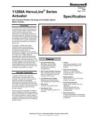
Thermostatic Expansion Valves<br />
The same features and design principles found in thermostatic<br />
expansion valves for Refrigerants – 12, 22, 134a, and 502 are<br />
also incorporated in Sporlan thermostatic expansion valves for<br />
Ammonia. They have proven their value and acceptance in the<br />
Industry for over 65 years.<br />
nozzle. If the discharge tube is not removed from the valve, the<br />
combination of the discharge tube and distributor nozzle may<br />
create an excessive pressure drop resulting in a substantial loss<br />
of TEV capacity. Refer to page 8 for further information on<br />
ammonia distributors.<br />
Refrigerant 717 (Ammonia) Applications<br />
Thermostatic expansion valves for ammonia applications<br />
require special design considerations due to the erosive effects<br />
of ammonia vapor. For this type of application, Sporlan has<br />
developed the Types D and A thermostatic expansion valves.<br />
Like other components of ammonia systems, the Types D and<br />
A valves are made from steel and steel alloys. The materials<br />
used in the manufacture of these valves are listed on pages 4<br />
and 5.<br />
With ammonia systems, the formation of flash vapor at the<br />
expansion valve port causes valve seat erosion or wire drawing<br />
to occur. This effect is further aggravated by high velocity<br />
ammonia mixed with dirt or scale passing through the port of<br />
the expansion valve. Fortunately, seat erosion can be minimized<br />
and valve life extended if the following steps are taken:<br />
1. Maintain vapor-free liquid at the TEV inlet at all times.<br />
2. Maintain clean ammonia through effective filtration.<br />
3. Reduce the velocity of the ammonia through the TEV<br />
port by reducing the pressure drop across the port.<br />
Step 1 can be accomplished through proper system design.<br />
Liquid line vapor is prevented by adequately sizing liquid lines<br />
and providing sufficient subcooling.<br />
Step 2 can be assured with the use of a Sporlan Catch-All ®<br />
Filter-Drier. This filter-drier is an effective scale trap when<br />
used on ammonia systems. For further information on the use<br />
of the Catch-All Filter-Drier with ammonia systems, refer to<br />
Bulletin 40-10 and page 15 of this bulletin.<br />
Step 3 can be accomplished with the use of a removable discharge<br />
tube or the nozzle of a refrigerant distributor. These<br />
components reduce the velocity and pressure drop at the<br />
expansion valve port by introducing a restriction or added<br />
pressure drop in the valve outlet passage.<br />
The nominal 75 and 100 ton Type A valves do not employ a<br />
discharge tube since their valve outlets are designed to serve as<br />
a secondary orifice to reduce pressure drop across the valve<br />
port.<br />
Thermostatic Charges for Ammonia Valves<br />
Thermostatic charges C, Z, and L are available for the Type D<br />
thermostatic expansion valve. The Type L thermostatic charge<br />
is the only charge available for the Type A valve.<br />
The Types C and Z thermostatic charges provide operating<br />
advantages for systems that cycle in response to a suction<br />
pressure switch or thermostat. These charges are also recommended<br />
for systems using a small capacity compressor. The<br />
table below lists the recommended temperature range for each<br />
charge.<br />
THERMOSTATIC<br />
CHARGE<br />
EVAPORATOR<br />
TEMPERATURE<br />
° F<br />
C 40° to 0°<br />
Z 0° to -20°<br />
For applications at evaporator temperature below -20°F, consult<br />
Sporlan Valve Company, Washington, Missouri 63090.<br />
Cold storage plants often have large centralized ammonia systems<br />
consisting of many evaporators connected to one or more<br />
large compressors. This makes for fairly stable suction pressures.<br />
The Sporlan type L charge responds more quickly to<br />
changes in bulb temperature allowing for a quicker pull-down<br />
of the conditioned space temperature. Therefore, for large<br />
ammonia systems consisting of multiple evaporators, the Type<br />
L charge is recommended.<br />
The removable discharge tube is threaded into the outlet of the<br />
Type D valves, and the nominal 20, 30, and 50 ton Type A<br />
valves. The discharge tube is the principle difference between<br />
ammonia TEVs and TEVs used with other refrigerants.<br />
Discharge tube sizes are listed in the Type D and A valve specifications<br />
on pages 4 and 5.<br />
The discharge tube in the outlet passage must be removed when<br />
the TEV is combined with a Sporlan ammonia distributor and
Page 4<br />
CATALOG<br />
Type D – FPT Flange Connections<br />
The Sporlan Type D valve is an externally adjustable valve<br />
with a gray cast iron body. It is available with either FPT or<br />
socket weld flange connections. The thermostatic element is<br />
replaceable, and all internal parts are serviceable. An optional<br />
XD-074 (1/2” FPT) external inlet strainer may be ordered with<br />
this valve. The nominal 1 and 2 ton Type D valves are identical,<br />
with the exception of their discharge tubes, as are the nominal<br />
10 and 15 ton valves. One of these valves can be<br />
converted to the other by exchanging the discharge tubes.<br />
Refrigerant distributors that will mate directly to this valve are<br />
listed below. Refer to Sporlan Bulletin 20-10 for additional<br />
application information on this subject.<br />
Note: The discharge tube must be<br />
removed when a refrigerant distributor<br />
is applied to the valve.<br />
Outlet Connections<br />
“D” flange<br />
Distributors<br />
1130, 1132, 1133, 1180 (aluminum)<br />
1182 (aluminum)<br />
Internal<br />
Equalizer<br />
TYPE<br />
External<br />
Equalizer<br />
1/8" FPT<br />
NOMINAL<br />
CAPACITY<br />
Tons of<br />
Refrigeration<br />
SPECIFICATIONS – ELEMENT SIZE NO. 23, GASKET JOINT<br />
Port<br />
Size<br />
Inches<br />
Discharge<br />
Tube Orifice<br />
Inches<br />
DA-1<br />
DAE-1<br />
1 1/16<br />
1/32<br />
DA-2<br />
DAE-2<br />
2 1/16<br />
1/16<br />
DA-5<br />
DAE-5<br />
5 7/64<br />
5/64<br />
DA-10<br />
DAE-10<br />
10<br />
3/16<br />
7/64<br />
DA-15<br />
DAE-15<br />
15<br />
3/16<br />
5/32<br />
Thermostatic<br />
Charges Available<br />
C-Z-L<br />
Bold<br />
figures are standard and will be<br />
furnished unless otherwise specified.<br />
Std. Tubing<br />
Length – Ft.<br />
5<br />
10<br />
15<br />
CONNECTIONS<br />
– Inches<br />
FPT<br />
INLET<br />
OUTLET<br />
Flange Ring<br />
Size OD X ID<br />
Inches<br />
Net Weight – Lbs.<br />
Shipping<br />
Weight – Lbs.<br />
1/4,<br />
3/8, or 1/<br />
2<br />
1.12<br />
x 0.75<br />
8 9<br />
2.31<br />
2.75<br />
Discharge Tube<br />
BULB SIZES – Inches<br />
CHARGES<br />
REFRIGERANT<br />
717 – Ammonia<br />
C - Z - L 0.75 x 4.00<br />
1.38<br />
Compact combination of XD<br />
Strainer – MA5A3 Solenoid<br />
Valve – DA Thermostatic<br />
Expansion Valve & 1130<br />
Steel Distributor<br />
4.06<br />
Inlet Strainer<br />
Screen<br />
Assembly<br />
1/16 Port<br />
P/N 3777-000<br />
7/64 & 3/16<br />
Port<br />
P/N 3777-001<br />
3.25<br />
5.06<br />
Types XD Strainer –<br />
DA Thermostatic<br />
Expansion Valve &<br />
1132 Steel Distributor<br />
VALVE<br />
TYPE<br />
D<br />
BODY<br />
Gray Iron<br />
Casting<br />
SEAT<br />
Stainless<br />
Steel or<br />
Steel Alloy<br />
MATERIALS & DETAILS OF CONSTRUCTION<br />
PIN<br />
TYPE of<br />
PIN<br />
PUSHROD(S)<br />
CARRIER<br />
JOINTS<br />
Tungsten<br />
Carbide<br />
Stainless<br />
Steel<br />
Stainless<br />
Steel<br />
Gasket<br />
CONNECTIONS<br />
Pipe Flange,<br />
Socket Weld<br />
INLET<br />
STRAINER<br />
Removable<br />
Strainer<br />
Screen
CATALOG<br />
Page 5<br />
Type A – FPT Flange Connections<br />
The Sporlan Type A valve is an externally adjustable valve<br />
with a gray cast iron body and either FPT or socket weld<br />
flange connections. The thermostatic<br />
element is replaceable.<br />
An optional 8004 (1/2”<br />
FPT) or 8006 (3/4” FPT)<br />
strainer may be ordered with<br />
this valve.<br />
The nominal 20 and 30 ton<br />
Type A valves are identical<br />
with the exception of their discharge<br />
tubes. One of these<br />
valves can be converted to the<br />
other by exchanging their discharge tubes. The nominal 75 and<br />
100 ton Type A valves do not employ a discharge tube, nor are<br />
their outlets tapped to receive one.<br />
Refrigerant distributors that will mate directly to this valve are<br />
listed below. Refer to Sporlan Bulletin 20-10 for additional<br />
application information on this subject. Note: The discharge<br />
tube must be removed from the nominal 20, 30, and 50 ton<br />
Type A valves when a refrigerant distributor is applied.<br />
Outlet Connections<br />
“A” flange<br />
Distributors<br />
1138, 1185 (aluminum)<br />
Internal<br />
Equalizer<br />
TYPE<br />
External<br />
Equalizer<br />
1/8" FPT<br />
NOMINAL<br />
CAPACITY<br />
Tons of<br />
Refrigeration<br />
SPECIFICATIONS<br />
Port<br />
Size<br />
Inches<br />
Discharge<br />
Tube Orifice<br />
Inches<br />
AA-20<br />
AAE-20<br />
20<br />
5/16<br />
1/ 8<br />
AA-30<br />
AAE-30<br />
30<br />
5/16<br />
5/32<br />
AA-50<br />
AAE-50<br />
50<br />
3/<br />
8 3/16<br />
AA-75<br />
AAE-75<br />
75<br />
3 / 8 –<br />
AA-100<br />
AAE-100<br />
100<br />
7 /16<br />
–<br />
– ELEMENT SIZE NO. 12, GASKET JOINT<br />
Thermostatic<br />
Charges Available<br />
L<br />
Only<br />
Bold<br />
figures are standard and will be<br />
furnished unless otherwise specified.<br />
Std. Tubing<br />
Length – Ft.<br />
10<br />
15<br />
CONNECTIONS<br />
– Inches<br />
FPT<br />
INLET<br />
1 /2, 3/4, or 1<br />
3/4<br />
or 1<br />
OUTLET<br />
Flange Ring<br />
Size OD x ID<br />
Inches<br />
Net Weight – Lbs.<br />
Shipping<br />
Weight – Lbs.<br />
1.75<br />
x 1.25 10<br />
11<br />
2.38<br />
3.62<br />
BULB SIZES – Inches<br />
CHARGE<br />
REFRIGERANT<br />
717 – Ammonia<br />
L - Only 0.88 OD x 6.00<br />
5.00<br />
Inlet Strainer<br />
Screen<br />
Assembly<br />
P/N 1471-000<br />
5.38<br />
8004 Strainer – AA<br />
Thermostatic Expansion<br />
Valve & 1185 Aluminum<br />
Distributor<br />
7.25<br />
VALVE<br />
TYPE<br />
A<br />
BODY<br />
Gray Iron<br />
Casting<br />
SEAT<br />
Stainless<br />
Steel<br />
MATERIALS & DETAILS OF CONSTRUCTION<br />
PIN<br />
TYPE of<br />
PIN<br />
PUSHROD(S)<br />
CARRIER<br />
JOINTS<br />
20 & 30 Ton:<br />
Tungsten Carbide Stainless Stainless<br />
50, 75, & 100 Ton: Steel Steel<br />
Gasket<br />
Stainless Steel<br />
CONNECTIONS<br />
Pipe Flange,<br />
Socket Weld<br />
INLET<br />
STRAINER<br />
Removable<br />
Strainer<br />
Screen
Page 6<br />
CATALOG<br />
Thermostatic Expansion Valve Capacities – Tons of Refrigeration<br />
These ratings are based on vapor free 86°F liquid refrigerant entering the TEV, a maximum opening superheat of 7°F, and a<br />
standard factory air test setting.<br />
AC and AL THERMOSTATIC CHARGES<br />
EVAPORATOR<br />
TEMPERATURE ° F<br />
VALVE NOMINAL PORT DISCHARGE<br />
40°<br />
20°<br />
5°<br />
TYPE CAPACITY SIZE TUBE SIZE<br />
PRESSURE DROP ACROSS VALVE – psi<br />
80<br />
100<br />
120<br />
140<br />
100<br />
120<br />
140<br />
160<br />
100<br />
120<br />
140<br />
160<br />
D 1 1/16<br />
1/32<br />
1.08<br />
1.21<br />
1.32<br />
1.43<br />
1.02<br />
1.12<br />
1.21<br />
1.29<br />
0.85<br />
0.93<br />
1.00<br />
1.07<br />
D 2 1/16<br />
1/16<br />
2.16<br />
2.41<br />
2.64<br />
2.86<br />
2.05<br />
2.24<br />
2.42<br />
2.59<br />
1.69<br />
1.85<br />
2.00<br />
2.14<br />
D 5 7/64<br />
5/64<br />
5.40<br />
6.03<br />
6.61<br />
7.14<br />
5.12<br />
5.61<br />
6.05<br />
6.47<br />
4.23<br />
4.63<br />
5.00<br />
5.35<br />
D 10<br />
3/16<br />
7/64<br />
10.<br />
8 12.<br />
1 13.<br />
2 14.<br />
3 10.<br />
2 11.<br />
2 12.<br />
1 12.<br />
9 8.45<br />
9.26<br />
10.<br />
0 10. 7<br />
D 15<br />
3/16<br />
5/32<br />
16.<br />
2 18.<br />
1 19.<br />
8 21.<br />
4 15.<br />
4 16.<br />
8 18.<br />
2 19.<br />
4 12.<br />
7 13.<br />
9 15.<br />
0 16. 0<br />
A 20<br />
5/16<br />
1/<br />
8 19.<br />
3 21.<br />
6 23.<br />
6 25.<br />
5 18.<br />
8 20.<br />
6 22.<br />
2 23.<br />
7 16.<br />
9 18.<br />
5 20.<br />
0 21. 4<br />
A 30<br />
5/16<br />
5/32<br />
28.<br />
9 32.<br />
3 35.<br />
4 38.<br />
2 28.<br />
1 30.<br />
8 33.<br />
3 35.<br />
6 25.<br />
4 27.<br />
8 30.<br />
0 32. 1<br />
A 50<br />
3/<br />
8<br />
3/16<br />
48.<br />
2 53.<br />
9 59.<br />
0 63.<br />
7 46.<br />
9 51.<br />
4 55.<br />
5 59.<br />
3 42.<br />
3 46.<br />
3 50.<br />
0 53. 5<br />
A 75<br />
3 / 8<br />
– 72.<br />
3 80.<br />
8 88.<br />
5 95.<br />
6 70.<br />
4 77.<br />
1 83.<br />
3 89.<br />
0 63.<br />
4 69.<br />
4 75.<br />
0 80. 2<br />
A 100<br />
7 /16<br />
– 96.<br />
4 108<br />
118<br />
127<br />
93.<br />
8 103<br />
111<br />
119<br />
84.<br />
5 92.<br />
6 100<br />
107<br />
AZ and AL THERMOSTATIC CHARGES<br />
EVAPORATOR<br />
TEMPERATURE ° F<br />
VALVE NOMINAL PORT DISCHARGE<br />
- 10°<br />
-20°<br />
TYPE CAPACITY SIZE TUBE SIZE PRESSURE DROP ACROSS VALVE – psi<br />
120<br />
140<br />
160<br />
180<br />
120<br />
140<br />
160<br />
180<br />
D 1 1/16<br />
1/32<br />
0.61<br />
0.66<br />
0.71<br />
0.75<br />
0.52<br />
0.56<br />
0.60<br />
0.63<br />
D 2 1/16<br />
1/16<br />
1.06<br />
1.14<br />
1.22<br />
1.29<br />
0.89<br />
0.96<br />
1.03<br />
1.09<br />
D 5 7/64<br />
5/64<br />
2.48<br />
2.68<br />
2.87<br />
3.04<br />
2.09<br />
2.26<br />
2.42<br />
2.56<br />
D 10<br />
3/16<br />
7/64<br />
5.24<br />
5.66<br />
6.05<br />
6.42<br />
4.42<br />
4.78<br />
5.11<br />
5.42<br />
D 15<br />
3/16<br />
5/32<br />
7.27<br />
7.85<br />
8.39<br />
8.90<br />
6.13<br />
6.62<br />
7.08<br />
7.51<br />
A 20<br />
5/16<br />
1/<br />
8 15.<br />
9 17.<br />
2 18.<br />
4 19.<br />
5 13.<br />
6 14.<br />
7 15.<br />
8 16. 7<br />
A 30<br />
5/16<br />
5/32<br />
23.<br />
9 25.<br />
8 27.<br />
6 29.<br />
3 20.<br />
5 22.<br />
1 23.<br />
6 25. 1<br />
A 50<br />
3/<br />
8<br />
3/16<br />
39.<br />
9 43.<br />
1 46.<br />
0 48.<br />
8 34.<br />
1 36.<br />
9 39.<br />
4 41. 8<br />
A 75<br />
3 / 8<br />
– 59.<br />
8 64.<br />
6 69.<br />
1 73.<br />
2 51.<br />
2 55.<br />
3 59.<br />
1 62. 7<br />
A 100<br />
7 /16<br />
– 79.<br />
7 86.<br />
1 92.<br />
1 97.<br />
7 68.<br />
2 73.<br />
7 78.<br />
8 83. 6<br />
LIQUID TEMPERATURE ENTERING TEV ° F<br />
REFRIGERANT 0 ° 10°<br />
20°<br />
30°<br />
40°<br />
50°<br />
60°<br />
70°<br />
80°<br />
86°<br />
90°<br />
100°<br />
CORRECTION FACTOR, CF LIQUID TEMPERATURE<br />
717<br />
1.27<br />
1.24<br />
1.20<br />
1.17<br />
1.14<br />
1.11<br />
1.08<br />
1.05<br />
1.02<br />
1.00<br />
0.99<br />
0.96<br />
EXAMPLE: Actual capacity of nominal 10 ton valve at -10°F evaporator,<br />
160 psi pressure drop and 60°F liquid temperature = 6.05<br />
tons x 1.08 = 6.53 tons.<br />
These factors include corrections for liquid refrigerant density and net refrigerating effect and are based on an average evaporator temperature<br />
of 0°F. However, they may be used for any evaporator temperature from -20°F to 40°F since the variation in the actual factors<br />
across this range is insignificant.
CATALOG Page 7<br />
Selection Procedure<br />
The following procedure should be used when selecting a<br />
Refrigerant 717 Ammonia TEV:<br />
1. Determine the pressure drop across the valve.<br />
Subtract the evaporating pressure from the condensing pressure.<br />
The condensing pressure used in this calculation should be the<br />
minimum operating condensing pressure of the system. From<br />
this value, subtract all other pressure losses to obtain the net<br />
pressure drop across the valve. Be sure to consider all of the following<br />
possible sources of pressure drop: (1) friction losses<br />
through refrigeration lines including the evaporator and condenser;<br />
(2) pressure drop across liquid line accessories such as a<br />
solenoid valve and filter-drier; and (3) static pressure loss (gain)<br />
due to the vertical lift (drop) of the liquid line, see Table 1.<br />
Table 1<br />
VERTICAL LIFT – FEET<br />
REFRIGERANT 20<br />
40<br />
60<br />
80<br />
100<br />
STATIC PRESSURE LOSS – psi<br />
717<br />
Ammonia 5 10<br />
15<br />
20<br />
25<br />
It is not necessary to subtract the pressure drop across the<br />
refrigerant distributor when determining the pressure drop<br />
across a Sporlan Type D or Type A valve with a nominal rating<br />
of 50 tons or less. These valves employ a discharge tube in<br />
the valve outlet passageway, and it should be removed when a<br />
distributor is connected to the valve. Sporlan distributors are<br />
normally selected to provide a 40 psi pressure drop at design<br />
load conditions for ammonia applications. Removing the discharge<br />
tube from the valve will compensate for this pressure<br />
drop. Refer to Bulletin 20-10 for further information on refrigerant<br />
distributors.<br />
2. Determine the liquid temperature of the<br />
refrigerant entering the valve.<br />
The R-717 Ammonia TEV rating tables on page 6 are based on<br />
a liquid temperature of 86°F. For other liquid temperatures,<br />
apply the correction factor given in the table.<br />
EVAPORATOR TEMPE<br />
20°<br />
SSURE DROP ACROSS V<br />
120 140 160<br />
0.93 1.00 1.07<br />
1.85 2.00 2.14<br />
4.63 5.00 5.35<br />
9.26 10.0 10.7<br />
The valve capacity should equal<br />
or slightly exceed the tonnage<br />
rating of the system.<br />
a. Design<br />
evaporating<br />
temperature<br />
b. Available pressure drop<br />
CAPACITY (tons)<br />
EVAPORATING TEMP<br />
Condensing<br />
Temp. (°F)<br />
0° 5° 10°<br />
80° 3.1 5.2 7.2<br />
90° 2.8 5.0 6.9<br />
100° 2.5 4.7 6.6<br />
3. Select valve from the rating tables.<br />
Select a valve based on the design evaporating temperature<br />
and the available pressure drop across the valve. If possible,<br />
the valve rating should equal or slightly exceed the design rating<br />
of the system. Be sure to apply the appropriate liquid temperature<br />
correction factor to the valve ratings shown in the<br />
tables. Once the desired valve rating has been located, determine<br />
the nominal capacity of the valve from the second column<br />
of the table. On multiple evaporator systems, select each<br />
valve on the basis of individual evaporator capacity.<br />
4. Determine if an external equalizer is required.<br />
The amount of pressure drop between the valve outlet and bulb<br />
location will determine if an external equalizer is required. The<br />
recommendations given in Table 1 are suitable for most field<br />
installed systems. Use an externally equalized valve when pressure<br />
drop between the valve outlet and bulb location exceeds<br />
values shown in Table 2. An externally equalized valve must be<br />
used on evaporators, which employ a refrigerant distributor.<br />
Table 2<br />
EVAPORATOR<br />
TEMPERATURE ° F<br />
REFRIGERANT<br />
40<br />
20<br />
0 -20<br />
PRESSURE DROP – psi<br />
717<br />
Ammonia<br />
3 2 1.<br />
5 1. 0<br />
When the thermostatic expansion valve is equipped with an<br />
external equalizer, it must be connected. Do not cap off the<br />
equalizer connection, as it will prevent the valve from operating<br />
properly.<br />
5. Select the Sporlan Selective Thermostatic Charge<br />
Select the charge according to the design evaporator temperature<br />
and the valve application. The subject of R-717 thermostatic<br />
charges is discussed on page 3. Refer to Bulletin 10-9 for<br />
a complete discussion of Sporlan Selective Thermostatic<br />
Charges.<br />
Selection Example:<br />
Refrigerant 717<br />
Application: Refrigeration, single evaporator system<br />
Design evaporator temperature 5°F<br />
Design condenser temperature 90°F<br />
Refrigerant liquid temperature 80°F<br />
Design evaporator capacity<br />
5 tons<br />
Available pressure drop across TEV<br />
Condensing pressure (psig) 166<br />
Evaporator pressure (psig) -19<br />
147<br />
Liquid line and accessories loss (psi) -7<br />
Distributor and tubes loss (psi) ➀ 0<br />
140<br />
Refrigerant liquid correction factor 1.02<br />
The DAE-5 has a valve capacity of: 5.00 x 1.02 = 5.10 tons at<br />
5°F evaporator temperature, 140 psi pressure drop, and 80°F<br />
liquid temperature.<br />
Thermostatic charge, see page 3: C<br />
Selection: DAE-5-C<br />
➀ An externally equalized valve must be used on evaporators<br />
employing a refrigerant distributor due to the pressure drop created<br />
by the distributor. Pressure drop due to the distributor is not<br />
used in the calculation to determine pressure drop across the TEV<br />
since the valve’s discharge tube will be removed. Refer to step 1 of<br />
the selection procedure.
Page 8<br />
CATALOG<br />
Refrigerant Distributors<br />
Direct Expansion – Steel & Aluminum<br />
Models – Flange Connections<br />
Sporlan refrigerant distributors for R-717 function like<br />
our conventional brass models.<br />
Steel models – The distributor body is Type 8620 vacuum<br />
degassed steel. The nozzle is Type 303 stainless steel,<br />
and the dispersion cone in the distributor is made of<br />
Stellite.<br />
Distributor tube connections are available for 3/16", 1/4",<br />
and 5/16" OD steel tubing. The ODF connections are<br />
trepanned to facilitate welding the joint. A 1/8" NPT connection<br />
is also available with Types 1130, 1133, and 1138<br />
distributors.<br />
Aluminum models – These distributors are designed for<br />
R-717 aluminum coils, and they are 6061-T6 aluminum.<br />
As with the steel distributors, the dispersion cone is<br />
Stellite, and the nozzle is stainless steel.<br />
Distributor tube connections are available for 3/16", 1/4",<br />
and 5/16" OD aluminum tubing. Aluminum brazing techniques<br />
require more space between circuits than copper<br />
to brass brazing. As a result, the maximum number of<br />
circuits is less than for comparable brass models.<br />
Applying Distributors to Thermostatic<br />
Expansion Valves<br />
All Type D and Type A TEVs up to and including 50 tons,<br />
employ a discharge tube. The discharge tube reduces<br />
refrigerant velocity across the valve port, preventing premature<br />
pin and seat erosion. When a distributor is used<br />
with these valves, the distributor nozzle performs the discharge<br />
tube’s function. The discharge tube must then be<br />
removed from the valve to avoid excessive pressure drop.<br />
Distributor performance is best obtained if the distributor<br />
is bolted directly to the TEV outlet. When it is not<br />
possible to bolt the TEV to the distributor, or if a shut off<br />
valve is installed between them, use a short, straight<br />
piece of pipe to connect the two. The pipe should not<br />
exceed two feet. It should be sized to maintain high<br />
refrigerant velocities. Elbows between the TEV and distributor<br />
are not recommended since they hinder proper<br />
distribution.<br />
Ratings for Refrigerant 717 Distributors<br />
Full load ratings are based on 30 psi nozzle, 10 psi tube pressure<br />
drop and 86° liquid temperature entering thermostatic<br />
expansion valve.<br />
Distributor Tube Circuit Capacities<br />
Tons of Refrigeration – Tube Length 30”<br />
REFRIGERANT<br />
DISTRIBUTOR<br />
717 Ammonia<br />
T UBE<br />
OD<br />
– Inches<br />
EVAPORATOR<br />
TEMPERATURE ° F<br />
40°<br />
20°<br />
5 ° - 10°<br />
- 20°<br />
-30°<br />
3/16<br />
1.79<br />
1.27<br />
1.01<br />
0.82<br />
0.72<br />
0.64<br />
1/4<br />
4.52<br />
3.20<br />
2.55<br />
2.07<br />
1.82<br />
1.62<br />
5/16<br />
9.73<br />
6.90<br />
5.50<br />
4.46<br />
3.93<br />
3.49<br />
1/8"<br />
Pipe* 12.<br />
0 8.50<br />
6.77<br />
5.50<br />
4.84<br />
4.30<br />
* Schedule 40<br />
LIQUID TEMPERATURE ENTERING TEV ° F<br />
REFRIGERANT 35°<br />
45°<br />
55°<br />
65°<br />
75°<br />
86°<br />
95°<br />
CORRECTION FACTOR, CF LIQUID TEMPERATURE<br />
717<br />
2.95<br />
2.15<br />
1.58<br />
1.33<br />
1.17<br />
1.00<br />
0.85<br />
Distributor Nozzle Orifice Capacities for Ammonia<br />
at Various Evaporator Temperatures<br />
Tons of Refrigeration<br />
To use the table below, knowing total load in tons and evaporator<br />
temperature, find nearest capacity in the table. On same horizontal<br />
line in extreme left column is the Distributor Nozzle Orifice<br />
Number to order. For example: 5.3 ton load at minus 10°F would<br />
require Nozzle Orifice Number 12A.<br />
REFRIGERANT<br />
DISTRIBUTOR<br />
717 Ammonia<br />
NOZZLE<br />
NUMBER<br />
EVAPORATOR TEMPERATURE ° F<br />
40°<br />
20°<br />
5 ° - 10°<br />
- 20°<br />
-30°<br />
1A<br />
0.65<br />
0.48<br />
0.41<br />
0.35<br />
0.32<br />
0.30<br />
1-1/2A<br />
1.07<br />
0.79<br />
0.66<br />
0.58<br />
0.53<br />
0.50<br />
2A<br />
1.42<br />
1.05<br />
0.88<br />
0.76<br />
0.70<br />
0.65<br />
2-1/2A<br />
2.03<br />
1.50<br />
1.26<br />
1.09<br />
1.00<br />
0.94<br />
3A<br />
2.62<br />
1.93<br />
1.62<br />
1.40<br />
1.30<br />
1.21<br />
4A<br />
3.01<br />
2.22<br />
1.86<br />
1.61<br />
1.49<br />
1.39<br />
5A<br />
4.07<br />
3.01<br />
2.52<br />
2.19<br />
2.02<br />
1.88<br />
6A<br />
4.95<br />
3.66<br />
3.07<br />
2.66<br />
2.45<br />
2.29<br />
8A<br />
6.83<br />
5.05<br />
4.23<br />
3.67<br />
3.38<br />
3.15<br />
10A<br />
8.10<br />
5.98<br />
5.02<br />
4.35<br />
4.01<br />
3.74<br />
12A<br />
9.64<br />
7.12<br />
5.98<br />
5.17<br />
4.77<br />
4.45<br />
15A<br />
13.<br />
1 9.69<br />
8.13<br />
7.04<br />
6.50<br />
6.06<br />
18A<br />
16.<br />
3 12.<br />
1 10.<br />
1 8.77<br />
8.09<br />
7.55<br />
20A<br />
17.<br />
4 12.<br />
8 10.<br />
8 9.31<br />
8.59<br />
8.01<br />
25A<br />
22.<br />
2 16.<br />
4 13.<br />
7 11.<br />
9 11.<br />
0 10. 2<br />
30A<br />
29.<br />
2 21.<br />
6 18.<br />
1 15.<br />
7 14.<br />
5 13. 5<br />
35A<br />
34.<br />
8 25.<br />
7 21.<br />
6 18.<br />
7 17.<br />
2 16. 1<br />
40A<br />
39.<br />
2 29.<br />
0 24.<br />
3 21.<br />
0 19.<br />
4 18. 1<br />
50A<br />
49.<br />
5 36.<br />
6 30.<br />
7 26.<br />
6 24.<br />
5 22. 9<br />
Ratings based on 86°F liquid entering TEV, 30 psi ∆P across nozzle,<br />
10 psi ∆P across distributor tubes, 30” tube length.<br />
For information on applications and capacities at evaporator temperatures<br />
below -30°F consult Sporlan Valve Company.<br />
NOTE: For direct expansion application with liquid temperatures<br />
lower than tabulated values or for flooded liquid recirculation systems<br />
– contact Sporlan Valve Company, Washington, MO 63090.
CATALOG Page 9<br />
Specifications<br />
The Types 1132 and 1180 ammonia distributors have a male<br />
flange ring and bolt directly to the outlet of the Type D valve.<br />
These distributors come with a companion flange, P/N 576-<br />
000. When specified, an aluminum companion flange, P/N<br />
1176-000, is available for the Type 1180 distributor.<br />
Two 7/16" – 14 THD 2" long bolts connect these distributors<br />
to the Type D valve.<br />
The Types 1130 and 1182 distributors do not require a companion<br />
flange. These distributors bolt directly to the Type D<br />
valve using two 7/16" – 14 THD 1-1/2" bolts.<br />
All distributors used with the Type D valve require flange gasket<br />
P/N 106-004.<br />
The Type 1138 and 1185 distributors have a male flange ring<br />
that bolts directly to the Type A valve.<br />
Two 1/2" – 13 THD 1-3/4" long bolts connect these distributors<br />
to the Type A valve.<br />
All distributors used with Type A valve require flange gasket<br />
P/N 106-003.<br />
D<br />
A<br />
F<br />
A<br />
NPT<br />
Connection<br />
Welded<br />
Connection<br />
C<br />
➀<br />
B<br />
C<br />
D<br />
➁<br />
B<br />
F<br />
➀ Male Flange<br />
G<br />
1.099 OD x .776 ID ➁ 1130-1182 Male Flange 1.099 OD x .776 ID<br />
1138-1185 Male Flange 1.718 OD x 1.281 ID<br />
Either NPT connection or<br />
welded connections of steel<br />
body distributors<br />
TYPE<br />
NO. CIRCUITS<br />
& TUBING SIZES<br />
AVAILABLE<br />
1132<br />
Steel<br />
2 to 5 - 3/16" - ODF Welded<br />
2 to 4 - 1/4" - ODF Welded<br />
2 to 3 - 5/16" - ODF Welded<br />
TYPE<br />
1180<br />
to 8 - 3/16"<br />
Aluminum<br />
2 - ODF Brazing<br />
2 to 6 - 1/4" - ODF Brazing<br />
TYPE<br />
1130<br />
to 10 -<br />
Steel<br />
2 3/16" - ODF Welded<br />
4 to 10 - 1/4" - ODF Welded<br />
2 to 6 - 5/16" - ODF Welded<br />
2 to 6 - 1/8" - NPT<br />
TYPE<br />
1182<br />
to 12 -<br />
Aluminum<br />
8 3/16" - ODF Brazing<br />
7 to 10 - 1/4" - ODF Brazing<br />
TYPE<br />
1138<br />
1 to 19 -<br />
Steel<br />
1 3/16" - ODF Welded<br />
6 to 14 - 1/4" - ODF Welded<br />
7 to 12 - 5/16" - ODF Welded<br />
2 to 10 - 1/8" - NPT<br />
TYPE<br />
1185<br />
to 20 -<br />
Aluminum<br />
8 3/16" - ODF Brazing<br />
6 to 16 - 1/4" - ODF Brazing<br />
2 to 11 - 5/16" - ODF Brazing<br />
NOZZLE<br />
ORIFICE<br />
NUMBERS<br />
AVAILABLE<br />
Net Weight -<br />
Approximately 9 oz.<br />
1A thru 30A<br />
Net Weight -<br />
Approximately 4 oz.<br />
1A thru 30A<br />
Net Weight -<br />
Approximately 1 lb., 10 oz.<br />
1A thru 30A<br />
Net Weight -<br />
Approximately 10 oz.<br />
1A thru 30A<br />
Net Weight -<br />
Approximately 3 lb., 6 oz.<br />
5A thru 50A<br />
Net Weight -<br />
Approximately 1 lb., 4 oz.<br />
5A thru 50A<br />
SPECIFICATIONS<br />
NOZZLE &<br />
RETAINER<br />
RING SIZE<br />
G<br />
Used in combination<br />
with Sporlan Valve<br />
Type DAE and<br />
XD Strainer or DAE,<br />
XD Strainer and<br />
MA5A3 Solenoid Valve,<br />
or XD Strainer, Steel<br />
Flange No. 225-G and<br />
Spacer Part No.1177.<br />
G<br />
Used in combination<br />
with Sporlan Valve<br />
Type DAE and<br />
XD Strainer or DAE,<br />
XD Strainer and<br />
MA5A3 Solenoid Valve,<br />
or XD Strainer with<br />
Spacer Part No.1177.<br />
C<br />
Used in combination<br />
with Sporlan Valve<br />
Type AAE and<br />
8004 Strainer or AAE, 8004<br />
Strainer and<br />
MA17A3 Solenoid Valve,<br />
or 8004 Strainer with<br />
Spacer Part No.1179.<br />
DISTRIBUTOR<br />
DIMENSIONS<br />
Inches<br />
A B C D E F G<br />
2.44<br />
1.12<br />
1.37<br />
0.25<br />
➀ – –<br />
2.50<br />
2.25<br />
2.75<br />
2.00<br />
➁<br />
2.87<br />
3.19<br />
3.06<br />
0.25<br />
0.50<br />
0.12<br />
0.62<br />
3.48<br />
2.69<br />
➁ 0.25<br />
0.75<br />
3.50
Page 10<br />
CATALOG<br />
Specifications<br />
Refrigerant Distributor with Auxiliary Side Connection<br />
The Type 1133 distributor bolts directly to the Type D valve. This distributor features a side<br />
connection for hot gas bypass, hot gas defrost, or reverse cycle defrost applications.<br />
Two 7/16” – 13 THD 2” long bolts connect these distributors to the Type D valve.<br />
E<br />
F<br />
A<br />
C<br />
D ➀<br />
B<br />
G<br />
➀ Male Flange<br />
1.099 OD x .776 ID<br />
TYPE<br />
NO. CIRCUITS<br />
& TUBING SIZES<br />
AVAILABLE<br />
1133<br />
NOZZLE<br />
ORIFICE<br />
NUMBERS<br />
AVAILABLE<br />
S teel<br />
Net<br />
Weight - Approximately 2 lb.,10 oz.<br />
2 to 10 - 3/16" - ODF Welded<br />
2 to 8 - 1/4" - ODF Welded<br />
2 to 6 - 5/16" - ODF Welded<br />
2 to 6 - 1/8" - NPT<br />
1A thru 30A 1<br />
SIDE<br />
C ONNECTIONS<br />
NOZZLE &<br />
DIMENSIONS<br />
RETAINER<br />
Inches<br />
RING SIZE<br />
NUMBER<br />
SIZE<br />
Inches<br />
A B C D E F G<br />
3/8 or<br />
1/2 FPT<br />
G<br />
Used in combination<br />
with Sporlan Valve<br />
Type DAE and XD Strainer<br />
or DAE,<br />
XD Strainer and<br />
MA5A3 Solenoid Valve,<br />
or XD Strainer with<br />
Spacer Part No.1177.<br />
3.44<br />
2.25<br />
2.75<br />
2.00<br />
0.25<br />
0.50<br />
1.25<br />
TYPE<br />
1132<br />
1180<br />
1130<br />
DIMENSIONS<br />
– Inches<br />
A B C D E<br />
0.19<br />
3.50<br />
1.19<br />
3.44<br />
1133<br />
1.38<br />
4.38<br />
1182<br />
3.44<br />
1138<br />
1185<br />
1176-000<br />
0.62<br />
576-000<br />
0.94<br />
1.56<br />
1.75<br />
4.00<br />
4.75<br />
4.12<br />
2.75<br />
FLANGE<br />
3.00<br />
2 .00<br />
– –<br />
A<br />
B<br />
C<br />
E<br />
Spacer<br />
Type XD Strainer<br />
Assembly - Type<br />
XD Strainer, Spacer<br />
& Distributor<br />
D<br />
8004 Strainer<br />
Adaptor - Spacer<br />
1179, 1138 Steel or<br />
1185 Aluminum<br />
Distributor<br />
Steel Flange No. 576-000<br />
for Type 1132 and 1180 Distributors<br />
A<br />
A<br />
Aluminum Flange No. 1176-000<br />
for Type 1180 Distributor<br />
B<br />
XD Strainer<br />
Adaptor - Spacer 1177,<br />
1130 & 1133 Steel or<br />
1182 Aluminum<br />
Distributor<br />
B<br />
C<br />
C<br />
XD Strainer<br />
Adaptor - Spacer 1177,<br />
Steel Flange No. 576-<br />
000, 1132 Steel or 1180<br />
Aluminum Distributor
CATALOG<br />
Page 11<br />
Solenoid Valves<br />
Selection – Capacity Ratings<br />
The following information should be available when selecting<br />
a Sporlan Solenoid Valve:<br />
With this information, the correct valve can be selected from<br />
the Selection Tables.<br />
▼<br />
▼<br />
▼<br />
▼<br />
Refrigerant or fluid to be controlled.<br />
Capacity required.<br />
MOPD – Maximum Operating Pressure Differential<br />
required.<br />
Electrical specifications – volts and cycles.<br />
For Liquid Line capacity data, see below and individual specification<br />
pages.<br />
All solenoid valves are tested and rated in accordance with<br />
A.R.I. Standard No. 760-94.<br />
SPECIFICATIONS<br />
TONS OF REFRIGERATION<br />
TYPE<br />
CONNECTION PORT SIZE<br />
PRESSURE DROP – psi<br />
NUMBER<br />
Inches<br />
Inches<br />
1 2 3 4 5<br />
XJH<br />
1/4<br />
NPT Female<br />
.109<br />
XOF<br />
3/8<br />
NPT Female<br />
.109<br />
3.91<br />
5.54<br />
6.79<br />
7.85<br />
8.78<br />
MA5A3<br />
1/4,<br />
3/8, 1/2 NPT Female<br />
. 140<br />
8.<br />
0<br />
11.<br />
3<br />
13.<br />
7<br />
16<br />
17. 8<br />
MA17A3<br />
1/2,<br />
3/4, or 1 NPT Female<br />
17/32<br />
73<br />
95<br />
120<br />
143<br />
160<br />
MA32P3<br />
1 or 1-1/4 NPT Female<br />
1 125<br />
176<br />
225<br />
250<br />
280<br />
MA42P3<br />
1-1/2<br />
NPT Female<br />
1-5/16<br />
275<br />
390<br />
500<br />
550<br />
625<br />
MA50P3<br />
2 NPT Female<br />
1-9/16<br />
500<br />
725<br />
875<br />
1000<br />
1110<br />
Refrigerant 717 capacities are based on 5°F evaporating and 86°F liquid.<br />
LIQUID TEMPERATURE ENTERING TEV ° F<br />
REFRIGERANT 0 ° 10°<br />
20°<br />
30°<br />
40°<br />
50°<br />
60°<br />
70°<br />
80°<br />
86°<br />
90°<br />
100°<br />
CORRECTION FACTOR, CF LIQUID TEMPERATURE<br />
717<br />
1.27<br />
1.24<br />
1.20<br />
1.17<br />
1.14<br />
1.11<br />
1.08<br />
1.05<br />
1.02<br />
1.00<br />
0.99<br />
0.96<br />
These factors include corrections for liquid refrigerant density and<br />
net refrigerating effect and are based on an average evaporator<br />
temperature of 0°F. However, they may be used for any evaporator<br />
temperature from -20°F to 40°F since the variation in the actual<br />
factors across this range is insignificant.
Page 12<br />
CATALOG<br />
Types XJH and XOF<br />
Application<br />
Type XJH and XOF solenoid valves are of the<br />
direct acting type and are designed for small<br />
capacity ammonia/oil service. Both of these<br />
valves may be mounted horizontal, on side, or<br />
in a vertical line.<br />
Ordering Instructions<br />
Be sure to specify Valve Type, Connections,<br />
Voltage, and Cycles.<br />
and<br />
Listed<br />
Types XJH and XOF<br />
TYPE<br />
XJH<br />
XOF<br />
STANDARD<br />
CONNECTIONS<br />
Inches<br />
1/4 NPT Female<br />
3/8 NPT Female<br />
SPECIFICATIONS – MKC-1 COIL<br />
NOMINAL LIQUID CAPACITIES<br />
MOPD<br />
Tons of Refrigeration<br />
PORT SIZE<br />
STANDARD COIL RATINGS<br />
psi<br />
AMMONIA<br />
Inches<br />
PRESSURE DROP – psi<br />
AC<br />
1 2 3 4 5 VOLTS/CYCLES<br />
WATTS<br />
24/50-60<br />
120/50-60<br />
. 109<br />
250<br />
3.91<br />
5.54<br />
6.79<br />
7.85<br />
8.78<br />
208/50-60 10<br />
240/50-60<br />
Dual 120-240/60<br />
▼ Safe working pressure 300 psi.<br />
▼ Dual voltage 4-wire coils, 120-240/60 are available at slight additional cost.<br />
For other voltages and cycles, consult Sporlan Valve Company, Washington, Missouri 63090.<br />
▼ Available with conduit boss or junction box at no extra charge.<br />
1.56 Coil Removal<br />
2.92<br />
1.60<br />
2.22<br />
Optional 1/2” Conduit Boss<br />
0.50<br />
45°<br />
1.00<br />
1.88<br />
Mounting Hole Pattern<br />
#8-32 x .31 Deep
CATALOG<br />
Page 13<br />
Types MA5A3 and MA17A3<br />
Application<br />
Type MA5A3 solenoid valve is of the direct acting type and designed specifically for ammonia<br />
service. The type MA17A3 is a pilot operated solenoid valve for ammonia service. It is also available<br />
with a direct connected stem, plunger, and piston assembly for suction line applications. To<br />
specify, add prefix D to the type number. Example: DMA17A3. MOPD for direct connected<br />
valves is 200 psi.<br />
For hot gas application add prefix H to type number. Example: HMA17A3.<br />
Both of these valves must be mounted in a horizontal line with the coil at the top.<br />
Type MA5A3 shown<br />
with XD Strainer and<br />
DA Thermostatic<br />
Expansion Valve<br />
Ordering Instructions<br />
Be sure to specify Valve Type, Connections, Voltage, and Cycles.<br />
Dimensions – Inches<br />
2-Bolt Flanges<br />
TYPE<br />
A B C D<br />
MA5A3<br />
3.25<br />
1.69<br />
2.75<br />
5.00<br />
MA17A3<br />
5.12<br />
3.25<br />
2.94<br />
5.12<br />
TYPE<br />
E F G H<br />
BOLT<br />
SIZE<br />
MA5A3<br />
0.75<br />
1.12<br />
0.12<br />
2.00<br />
7/16<br />
MA17A3<br />
1.25<br />
1.75<br />
0.16<br />
2.69<br />
1/ 2<br />
Type MA17A3<br />
and<br />
Listed<br />
3.50 Coil<br />
Removal<br />
3.27<br />
3.50 Coil<br />
Removal<br />
3.27<br />
D<br />
Type MA5A3<br />
D<br />
Type MA17A3<br />
1.99<br />
C<br />
E F H<br />
C<br />
B<br />
A<br />
G<br />
Optional 1/2” Conduit Boss<br />
B<br />
A<br />
TYPE<br />
MA5A3<br />
FLANGE<br />
CONNECTIONS<br />
Inches<br />
Sizes<br />
shown in BOLD<br />
will be furnished unless<br />
otherwise specified.<br />
PORT<br />
SIZE<br />
Inches<br />
SPECIFICATIONS – KC-3 COIL<br />
AC<br />
MOPD<br />
psi<br />
NOMINAL LIQUID CAPACITIES<br />
Tons of Refrigeration<br />
AMMONIA<br />
Pressure Drop – psi<br />
DC<br />
1 2 3 4 5<br />
1/4,<br />
3/8, or<br />
1/<br />
2 NPT<br />
Female<br />
. 140<br />
250<br />
200<br />
8.<br />
0 11.<br />
3 13.<br />
8 16.<br />
0 17. 8<br />
M A17A3 1 /2,<br />
3/4,<br />
or<br />
1 NPT Female<br />
17/32<br />
275<br />
225<br />
70.<br />
9 100<br />
122<br />
141<br />
157<br />
COIL RATINGS<br />
STANDARD<br />
VOLTS/CYCLES<br />
24/50-60<br />
120/50-60<br />
208/50-60<br />
240/50-60<br />
Dual 120-240/60<br />
WATTS<br />
AC<br />
DC<br />
18<br />
25<br />
▼ Maximum rated pressure 300 psi.<br />
▼ Dual voltage 4-wire coils, 120-240/60 are available at slight additional cost.<br />
For other voltages and cycles, consult Sporlan Valve Company, Washington, Missouri 63090.<br />
▼ Available with conduit boss or junction box at no extra charge.<br />
▼ Available with strainer inlet and one flange, with two flanges or without flanges.
Page 14<br />
CATALOG<br />
Types MA32, MA42, and MA50<br />
Application<br />
Types MA32, MA42, and MA50 are large capacity, pilot operated solenoid valves for refrigeration<br />
and air conditioning applications. They are suitable for suction service because very low<br />
pressure differential, 1 psi, is required for full operation.<br />
For hot gas application add prefix H to the type number. Example: HMA42P3, HMA32P3, etc.<br />
Type MA32P3<br />
Both of these valves must be mounted in a horizontal line with the coil at the top.<br />
Ordering Instructions<br />
Be sure to specify Valve Type, Connections, Voltage, and Cycles.<br />
Dimensions – Inches<br />
TYPE<br />
A B C D<br />
MA32P3<br />
8.25<br />
5.88<br />
3.06<br />
5.94<br />
MA42P3<br />
8.75<br />
6.62<br />
3.06<br />
6.69<br />
MA50P3<br />
9.88<br />
7.38<br />
3.88<br />
7.12<br />
4-Bolt Flanges<br />
TYPE<br />
E F G<br />
BOLT<br />
CIRCLE<br />
Diameter<br />
BOLT<br />
SIZE<br />
MA32P3<br />
1.81<br />
2.31<br />
0.12<br />
3.50<br />
5/ 8<br />
MA42P3<br />
2.12<br />
2.75<br />
0.16<br />
3.81<br />
5/ 8<br />
MA50P3<br />
2.50<br />
3.25<br />
0.16<br />
4.50<br />
5/ 8<br />
Type MA42P3<br />
and<br />
Listed<br />
3.50 Coil<br />
Removal<br />
3.27<br />
Spring Omitted<br />
on Types MA32<br />
and MA50<br />
D<br />
Type MA32P3,<br />
MA42P3, and<br />
MA50P3<br />
1.99<br />
C<br />
E<br />
F<br />
B<br />
A<br />
G<br />
Optional 1/2” Conduit Boss<br />
TYPE<br />
MA32P3<br />
MA42P3<br />
MA50P3<br />
FLANGE<br />
CONNECTIONS<br />
Inches<br />
Sizes<br />
shown in BOLD<br />
will be furnished unless<br />
otherwise specified.<br />
PORT<br />
SIZE<br />
Inches<br />
SPECIFICATIONS – KC-3 COIL<br />
AC<br />
MOPD<br />
psi<br />
NOMINAL LIQUID CAPACITIES<br />
Tons of Refrigeration<br />
AMMONIA<br />
Pressure Drop – psi<br />
DC<br />
1 2 3 4 5<br />
1 or<br />
1-1/<br />
4 NPT<br />
Female<br />
1 250<br />
175<br />
126<br />
178<br />
219<br />
253<br />
283<br />
1-1/2<br />
NPT Female<br />
1-5/16<br />
300<br />
175<br />
317<br />
429<br />
511<br />
582<br />
639<br />
2 NPT Female<br />
1-9/16<br />
300<br />
175<br />
566<br />
765<br />
913<br />
1039<br />
1140<br />
COIL RATINGS<br />
STANDARD<br />
VOLTS/CYCLES<br />
24/50-60<br />
120/50-60<br />
208/50-60<br />
240/50-60<br />
Dual 120-240/60<br />
WATTS<br />
AC<br />
DC<br />
18<br />
25<br />
▼ Maximum rated pressure 300 psi.<br />
▼ Dual voltage 4-wire coils, 120-240/60 are available at slight additional cost.<br />
For other voltages and cycles, consult Sporlan Valve Company, Washington, Missouri 63090.<br />
▼ Available with conduit boss or junction box at no extra charge.
CATALOG<br />
Page 15<br />
Replaceable Core Type<br />
Maximum Rated Pressure of 500 psi<br />
C US<br />
LISTED<br />
*P<br />
G<br />
D<br />
B<br />
diameter<br />
F<br />
C<br />
E<br />
G<br />
A<br />
TYPE<br />
C-484-P<br />
C-966-P<br />
C-1448-P<br />
C-19212-P<br />
CONNECTIONS<br />
Inches FPT<br />
1/2<br />
3/ 4<br />
1-1/<br />
2<br />
1-1/2<br />
NO. OF<br />
CORES<br />
1<br />
2<br />
3<br />
4<br />
CORE<br />
PART NO.<br />
RC-4864<br />
VOLUME<br />
OF<br />
DESICCANT<br />
SPECIFICATIONS<br />
MOUNTING<br />
BRACKETS<br />
Cu. In.<br />
48<br />
946<br />
14<br />
A-685<br />
192<br />
SHELL DIMENSIONS<br />
Inches<br />
A B C D E F G * P<br />
19.08<br />
15.85<br />
3.41<br />
17.50<br />
14.67<br />
20.42<br />
6.00<br />
5.00<br />
11.44<br />
3.48<br />
17.19<br />
3.66<br />
4 .75<br />
– 13.00<br />
18.62<br />
25.85 22.62 3.76<br />
24.25<br />
NET<br />
W EIGHT<br />
Lbs.<br />
SHIPPING<br />
W EIGHT<br />
Lbs.<br />
10<br />
12<br />
174<br />
106<br />
10 23<br />
2 2<br />
C-40016-P<br />
2-1/<br />
2<br />
4 RC-10098<br />
400<br />
A-175-2<br />
34.44<br />
7.50<br />
6.25<br />
30.38<br />
4.38<br />
6 .00<br />
– 32.12<br />
46<br />
51<br />
UL and UL C Listed. — Guide-SMGT-File No. SA-1756A & B.<br />
* “P” Dimension is the pull space required to change core.<br />
Ammonia Catch-All Filter-Driers<br />
The molded porous Catch-All core effectively removes scale<br />
and other fine particles – keeping the system clean – and prolonging<br />
the life of all moving parts.<br />
Small amounts of water are not considered a problem in<br />
ammonia systems. Therefore, the “drier” function of the desiccant<br />
core is not normally required.<br />
The Type C-413-P is a sealed model filter-drier. All of the<br />
other models shown at the right are replaceable core types.<br />
Use the RC-4864 or RC-10098 replaceable cores for excellent<br />
filtration ability.<br />
Note: Do not use RPE-48-BD and RPE-100 Filter Elements<br />
on ammonia systems.<br />
CATCH-ALL<br />
FILTER-DRIER<br />
TYPE<br />
FITTING<br />
SIZE<br />
FPT<br />
SELECTION<br />
RECOMMENDATIONS<br />
Tons<br />
REFRIGERANT<br />
FLOW<br />
CAPACITY<br />
Tons at 1 psi<br />
P<br />
REPLACEABLE<br />
CORE TYPE<br />
AND<br />
QUANTITY<br />
REQUIRED<br />
C-413-P<br />
3/<br />
8<br />
20<br />
58<br />
–<br />
C-484-P<br />
1/<br />
2<br />
40<br />
72<br />
RC-4864 (1)<br />
C-966-P<br />
3/<br />
4<br />
100<br />
189<br />
RC-4864 (2)<br />
C-1448-P<br />
1 150<br />
289<br />
RC-4864 (3)<br />
C-19212-P<br />
1-1/<br />
2<br />
300<br />
476<br />
RC-4864 (4)<br />
C-40016-P<br />
2 450<br />
696<br />
RC-10098 (4)<br />
Replaceable Cores – Order Separately<br />
Cores for replacement core type filter-driers are molded of<br />
exactly the same desiccants that are used in the popular sealed<br />
model filter-driers.<br />
Cores are individually packed in metal cans, fully activated,<br />
and hermetically sealed against moisture and dirt.<br />
The method of mounting the cores on the end plate by means<br />
of tie rods makes them very easy to install and remove.<br />
Replaceable core model Catch-Alls with pipe connections are<br />
supplied with an envelope containing 5 endplate gaskets.<br />
When replacement of endplate gasket is required, use one gasket<br />
from the envelope.
Page 16<br />
CATALOG<br />
Strainers<br />
C L<br />
G H<br />
IN<br />
A<br />
E<br />
F<br />
B<br />
diameter<br />
K diameter<br />
Special Purpose Strainer<br />
Type XD Strainer is for use with Ammonia and other liquids<br />
where a steel construction is suitable. May be used with companion<br />
flange or can be bolted directly to Type D thermostatic<br />
expansion valves and Type MA5A3 solenoid valves.<br />
Semi-cast steel body with FPT inlet and flanged outlet connections.<br />
Strainer screen is stainless steel with a seal plug for screen<br />
removal. Complete unit is zinc plated and painted. The maximum<br />
safe working pressure is 500 psig.<br />
TYPE<br />
NO.<br />
CONNECTIONS<br />
Inches<br />
INLET<br />
XD 074 1/<br />
2 FPT<br />
SCREEN<br />
SPECIFICATIONS<br />
MESH<br />
SIZE<br />
W EIGHT – L bs.<br />
DIMENSIONS<br />
– Inches<br />
AREA PART<br />
SHIP-<br />
OUTLET<br />
NET<br />
A B C E F G H K L<br />
Sq. In. NO.<br />
PING<br />
Flange<br />
6.<br />
6 635-3<br />
100<br />
1-3/<br />
4 3 4.19<br />
1.50<br />
2.25<br />
2.88<br />
2.00<br />
0.78<br />
1.09<br />
0.50<br />
0.13<br />
Strainers are supplied with female companion flange. Strainers can be ordered without the flange.<br />
“Y”Type Cast Semi-Steel Strainers<br />
Type 8000 Strainer is used primarily<br />
for Refrigerant 717 Ammonia, but can<br />
also be used for halocarbon refrigerants<br />
(R-22, R-134a, and R-404A) and other<br />
liquids where a steel construction is<br />
applicable. FPT inlet, standard two bolt<br />
York flange outlet connections. Types<br />
8004 and 8006 strainers can be<br />
bolted direct to the inlet of Type A thermostatic<br />
expansion valves or Type MA17A3 solenoid valves on<br />
Ammonia applications. The unit is zinc plated. The maximum<br />
safe working pressure is 500 psig.<br />
Type 9000 Strainers for large<br />
Refrigerant 717 Ammonia installations<br />
are also adaptable to halocarbon refrigerant<br />
(R-22, R-134a, and R-404A)<br />
applications, and other liquids where<br />
steel construction is suitable. The<br />
strainer is zinc plated. The maximum<br />
safe working pressure is 400 psig.<br />
FPT inlet, standard four bolt York flange outlet connections.<br />
The Type 9008 and 9010 strainers bolt directly to inlet<br />
of Types MA32P3 and DMA32P3 solenoid valves.<br />
E<br />
F<br />
L<br />
A<br />
E F<br />
L<br />
A<br />
D<br />
H G<br />
E F<br />
H G<br />
K diameter<br />
C<br />
C<br />
K diameter<br />
B<br />
diameter<br />
B<br />
diameter<br />
SPECIFICATIONS<br />
WEIGHT<br />
SCREEN<br />
DIMENSIONS<br />
– Inches<br />
TYPE CONNECTION<br />
MESH Lbs.<br />
NO. Inches AREA PART SIZE SHIP-<br />
NET<br />
A B C D E F G H K L<br />
Sq. In. NO.<br />
PING<br />
8004<br />
1 / 2 FPT*<br />
15<br />
4097-3<br />
80<br />
5 7 5.69<br />
2.75<br />
5.06<br />
2.06<br />
3.81<br />
2.69<br />
1.28<br />
1.75<br />
0.56<br />
8006<br />
3/4 FPT*<br />
0.13<br />
9008<br />
1 FPT* *<br />
11<br />
23<br />
4110-3<br />
60<br />
13<br />
7.56<br />
3.13<br />
7 .50<br />
– 2.44<br />
3.75<br />
1.81<br />
2.31<br />
0.75<br />
9010<br />
1-1 / 4 FPT*<br />
*<br />
10-1/<br />
2<br />
* Strainers are supplied without companion flange. Female companion flange, bolts, and gasket can be supplied when ordered.<br />
** Strainers are supplied without companion flange. Male companion flange, bolts, and gasket can be supplied when ordered.
CATALOG<br />
Page 17<br />
The Level Master Control<br />
Application and Installation<br />
The Sporlan Level-Master Control is a positive liquid level<br />
control device suitable for application to all flooded<br />
evaporators.<br />
Description and Operation<br />
The LMC is a standard thermostatic expansion valve equipped<br />
with a Level-Master Element. The combination provides a<br />
simple, economical, and highly effective liquid level control.<br />
The bulb of the conventional thermostatic element has been<br />
modified to an insert type of bulb that incorporates a low<br />
wattage heater. A 15-watt heater is supplied as standard.<br />
For applications below -60°F evaporating temperature<br />
specify a special 25-watt heater.<br />
The insert bulb is installed in the accumulator or surge drum<br />
at the point of the desired liquid level. As the level at the<br />
insert bulb drops, the electrically added heat increases the<br />
pressure within the thermostatic element and opens the valve.<br />
As the liquid level at the bulb rises, the electrical input is balanced<br />
by the heat transfer from the bulb to the liquid refrigerant<br />
and the LMC either modulates or eventually shuts off. The<br />
evaporator pressure and spring assist in providing a positive<br />
closure.<br />
Installation – General<br />
The Level-Master Control is applicable to any system<br />
that has been specifically designed for flooded<br />
operation.<br />
Sporlan is not responsible for system design and, therefore, is<br />
not liable for any damage arising from faulty design or<br />
improper piping, or for misapplication of its products. Figures<br />
2 through 4 are piping schematics only to illustrate possible<br />
methods of applying the LMC valves.<br />
If these valves are applied in any manner other than as<br />
described in this bulletin, the Sporlan warranty is void. Actual<br />
system piping must be done to protect the compressor at all<br />
times. This includes protection against overheating, slugging<br />
with liquid refrigerant, and trapping of oil in various locations.<br />
Sporlan recommends that recognized piping references, such<br />
as equipment manufacturers’ literature and the ASHRAE<br />
Guide and Data Book, be consulted for assistance with this<br />
subject.<br />
The valve is usually connected to feed into the surge drum<br />
above the liquid level. It can also feed into the liquid leg or coil<br />
header.<br />
The insert bulb can be installed directly into the shell, surge<br />
drum or liquid leg on new or existing installations. Existing<br />
float systems can be easily converted by installing the LMC<br />
insert bulb in the float chamber.<br />
The Level-Master Control may be installed at any ambient<br />
temperature. The element is protected against excessive temperature,<br />
created by the heater, by a thermostatic switch that is<br />
an integral part of the heater assembly.<br />
Installation – Insert Bulb<br />
The insert bulb should be installed at the point where the<br />
desired liquid level is to be maintained. The bulb must be<br />
in contact with the refrigerant, i.e., NOT installed in a<br />
well. If the insert bulb is projected directly into the surge drum,<br />
it should be shielded to prevent the possibility of splash from<br />
either the valve feed or the return from the coil. While generally<br />
installed in a horizontal position, see Figure 1, it will operate<br />
effectively at any angle or vertical position.<br />
Figure 1<br />
LIQUID<br />
LEVEL<br />
1-1/4” Male Pipe Thread<br />
1/2”<br />
Minor adjustments in liquid level can be made with the adjusting<br />
stem provided on the expansion valve. The insert bulb<br />
assembly is provided with a lock ring and gasket joint so that<br />
the bulb may be removed without breaking the pipe joint.<br />
Installation – Electrical Connections<br />
The heater is provided with a two-wire neoprene covered cord<br />
two feet in length. It runs through a moisture-proof grommet<br />
and a 1/2" male conduit connection affixed to the insert bulb<br />
assembly, see Figure 2.<br />
The heater circuit must be interrupted when refrigeration is<br />
not required and the compressor is cycled off. This will prevent<br />
shortening the life of the heater thermostat. To accomplish<br />
this, the heater is wired in parallel (on the compressor<br />
side) with the control or power relay, the holding coil of the<br />
compressor magnetic starter, or the liquid line solenoid valve.<br />
Figure 2<br />
Vertical Accumulator<br />
or Surge Drum<br />
Expansion Valve<br />
Strainer or<br />
Catch-All<br />
Liquid<br />
Level<br />
Surge<br />
Drum<br />
Typical Installation<br />
Suction Line<br />
To Coil<br />
Return from Coil<br />
Insert Bulb of Level<br />
Master Element<br />
Electrical Connections<br />
2-1/2” Pipe or Larger
Page 18<br />
CATALOG<br />
Design Precautions<br />
Hand Valves<br />
On installations where the valve is isolated from the surge<br />
drum by a hand valve, and a 2 to 3 pound pressure drop from<br />
the valve outlet to the bulb location is likely, we recommend<br />
that an externally equalized valve be used. (See ordering<br />
instructions.)<br />
Oil Return<br />
General – All reciprocating compressors will allow some oil<br />
to pass into the discharge line along with the discharge gas.<br />
Mechanical oil separators are used extensively; however, they<br />
are never completely effective. The untrapped oil passes<br />
through the condenser, liquid line, expansion device and finally<br />
into the evaporator.<br />
In a properly designed direct expansion system, the refrigerant<br />
velocity in the evaporator tubes and in the suction line is<br />
sufficiently high to ensure a continuous return of oil to the<br />
compressor crankcase. But, this is not characteristic of flooded<br />
systems. Here we purposely design the surge drum for a relatively<br />
low vapor velocity to prevent entrainment of liquid<br />
refrigerant droplets and consequent carryover into the suction<br />
line. This design criterion also prevents the return of any oil<br />
from the low side in the normal manner.<br />
reduction in the evaporator heat transfer rate can occur due to<br />
an increase in the refrigerant film resistance. Difficulty in<br />
maintaining the proper liquid level with any type of flooded<br />
control can also be expected.<br />
With a float valve, you can expect the liquid level in the evaporator<br />
to increase with high concentration of oil in a remote<br />
float chamber.<br />
If a Sporlan Level-Master Control is used with the insert bulb<br />
installed in a remote chamber, oil concentration at the bulb can<br />
cause overfeeding with possible floodback. The lower or liquid<br />
balance line must be free of traps and be free draining into<br />
the surge drum or chiller as shown in Figure 4. The oil drain<br />
leg or sump must be located at the lowest point in the low<br />
side.<br />
Figure 3<br />
Surge Drum<br />
LMC<br />
Suction<br />
Line<br />
Liquid<br />
Line<br />
And if oil is allowed to concentrate at the insert bulb location<br />
of the Sporlan Level-Master Control, overfeeding with possible<br />
floodback can occur. The tendency to overfeed is due to the<br />
fact that the oil does not convey the heat from the low wattage<br />
heater element away from the bulb as rapidly as does pure liquid<br />
refrigerant. The bulb pressure is higher than normal and<br />
the valve remains in the open or partially open position.<br />
Evaporator<br />
Oil Drain<br />
Oil and Ammonia Systems – Liquid ammonia and oil are<br />
immiscible for all practical purposes. And since the density of<br />
oil is greater than that of ammonia, it will fall to the bottom of<br />
any vessel containing such a mixture, if the mixture is relatively<br />
placid. Therefore, the removal of oil from an ammonia<br />
system is a comparatively simple task. Generally, on systems<br />
equipped with a surge drum, the liquid leg is extended downward<br />
below the point where the liquid is fed off to the evaporator<br />
and a drain valve is provided to allow periodic manual<br />
draining as shown in Figure 3.<br />
For flooded chillers that do not use a surge drum, a sump with<br />
a drain valve is usually provided at the bottom of the chiller<br />
shell.<br />
The above methods are quite satisfactory, except possibly on<br />
some low temperature systems. Here the drain leg or sump<br />
generally has to be warmed prior to attempting to draw off the<br />
oil since the trapped oil becomes quite viscous at lower<br />
temperatures.<br />
Figure 4<br />
Ammonia<br />
Horizontal<br />
Shell and Tube<br />
Chiller<br />
Typical Installation<br />
Liquid Level<br />
2-1/2” Pipe<br />
Shut-off Valve<br />
LMC<br />
Oil Drain<br />
2-1/2” Pipe<br />
1/2” Pipe<br />
Electrical<br />
Connections<br />
Liquid Line<br />
Catch-All or<br />
Strainer<br />
Insert<br />
Bulb of<br />
Level<br />
Master<br />
Element<br />
If oil is not drained from a flooded ammonia system, a
CATALOG<br />
Page 19<br />
Capacities and Selection<br />
Capacity in Tons of Refrigeration<br />
These ratings are based on vapor free (subcooled) liquid refrigerant entering<br />
the expansion valve (86°F for Refrigerant 717) and standard factory setting.<br />
Because of the artificial superheat provided by the electric heater the Level-<br />
Master will have a greater capacity than a conventional thermostatic expansion<br />
valve. For selections for other refrigerants, contact Sporlan Valve<br />
Company, Washington, Missouri 63090.<br />
REFRIGERANT 717 Ammonia CAPACITIES<br />
EVAPORATOR<br />
TEMPERATURE°<br />
F<br />
LMC<br />
NOMINAL 40°<br />
to 0°<br />
- 10°<br />
- 20°<br />
-40°<br />
VALVE<br />
CAPACITY<br />
TYPE<br />
PRESSURE DROP ACROSS VALVE – psi<br />
80<br />
100<br />
120<br />
140<br />
160<br />
100<br />
120<br />
140<br />
160<br />
180<br />
100<br />
120<br />
140<br />
160<br />
180<br />
100<br />
120<br />
140<br />
160<br />
180<br />
1 0.94<br />
1.06<br />
1.16<br />
1.25<br />
1.34<br />
0.98<br />
1.07<br />
1.15<br />
1.23<br />
1.31<br />
0.86<br />
0.94<br />
1.01<br />
1.08<br />
1.15<br />
0.59<br />
0.65<br />
0.70<br />
0.75<br />
0.80<br />
2 2.69<br />
3.01<br />
3.30<br />
3.56<br />
3.80<br />
2.77<br />
3.04<br />
3.28<br />
3.50<br />
3.71<br />
2.44<br />
2.67<br />
2.88<br />
3.08<br />
3.26<br />
1.68<br />
1.85<br />
1.99<br />
2.13<br />
2.26<br />
D 5 6.08<br />
6.80<br />
7.45<br />
8.05<br />
8.60<br />
6.26<br />
6.85<br />
7.41<br />
7.91<br />
8.39<br />
5.51<br />
6.03<br />
6.52<br />
6.97<br />
7.39<br />
3.81<br />
4.17<br />
4.51<br />
4.82<br />
5.11<br />
10<br />
11.<br />
0 12.<br />
3 13.<br />
5 14.<br />
6 15.<br />
6 11.<br />
3 12.<br />
4 13.<br />
4 14.<br />
4 15.<br />
2 9.96<br />
10.<br />
9 11.<br />
8 12.<br />
6 13.<br />
4 6.89<br />
7.56<br />
8.18<br />
8.74<br />
9.26<br />
15<br />
15.<br />
0 16.<br />
8 18.<br />
4 19.<br />
9 21.<br />
3 15.<br />
4 16.<br />
9 18.<br />
3 19.<br />
6 20.<br />
8 13.<br />
6 14.<br />
9 16.<br />
1 17.<br />
2 18.<br />
3 9.41<br />
10.<br />
3 11.<br />
1 11.<br />
9 12. 6<br />
20<br />
17.<br />
8 19.<br />
8 21.<br />
8 23.<br />
5 25.<br />
1 18.<br />
2 20.<br />
0 21.<br />
6 23.<br />
1 24.<br />
5 16.<br />
0 17.<br />
6 19.<br />
0 20.<br />
3 21.<br />
6 11.<br />
1 12.<br />
2 13.<br />
2 14.<br />
0 14. 9<br />
30<br />
30.<br />
0 33.<br />
6 36.<br />
8 39.<br />
7 42.<br />
4 30.<br />
9 33.<br />
8 36.<br />
5 39.<br />
0 41.<br />
4 27.<br />
2 29.<br />
8 32.<br />
2 34.<br />
3 36.<br />
4 18.<br />
8 20.<br />
6 22.<br />
2 23.<br />
7 25. 2<br />
A 50<br />
42.<br />
7 47.<br />
7 52.<br />
3 56.<br />
5 60.<br />
4 43.<br />
9 48.<br />
1 52.<br />
0 55.<br />
6 58.<br />
9 38.<br />
6 42.<br />
4 45.<br />
8 48.<br />
9 51.<br />
9 26.<br />
7 29.<br />
3 31.<br />
6 33.<br />
8 35. 9<br />
75<br />
75.<br />
1 84.<br />
0 92.<br />
0 99.<br />
4 106<br />
77.<br />
3 84.<br />
6 91.<br />
4 97.<br />
5 103<br />
68.<br />
0 74.<br />
5 80.<br />
5 85.<br />
9 91.<br />
1 47.<br />
0 51.<br />
5 55.<br />
7 59.<br />
4 63. 0<br />
100<br />
106<br />
118<br />
130<br />
140<br />
150<br />
108<br />
120<br />
129<br />
138<br />
146<br />
95.<br />
6 105<br />
113<br />
122<br />
129<br />
66.<br />
1 72.<br />
8 78.<br />
4 84.<br />
0 89. 1<br />
These factors include corrections for liquid refrigerant density<br />
and net refrigerating effect, and are based on an average evaporating<br />
temperature of 0°F. However, they may be used for any<br />
evaporator temperature from -40°F to 40°F since the variation<br />
in the actual factors across this range is insignificant.<br />
EXAMPLE: At -20°F evaporator, 160 psi pressure drop and 50°F liquid<br />
temperature, the capacity of an LMC-DA-10 (for ammonia) is<br />
12.6 x 1.11 = 14.0 tons.<br />
Ordering Instructions<br />
Complete Control Valve and Element:<br />
1. Valve type, per specification table. If an external equalizer is<br />
required, add "E" as the sixth letter. EXAMPLE: LMC-AAE-20<br />
2. Connection sizes and tubing lengths, if other than standard.<br />
3. Electrical characteristics.<br />
COMPLETE CONTROL<br />
VALVE & ELEMENT<br />
SPECIFICATIONS<br />
ELEMENT<br />
ONLY<br />
DISCHARGE<br />
TUBE<br />
INTERNAL ➀EXTERNAL<br />
Inches<br />
EQUALIZER EQUALIZER<br />
LMC-DA-1<br />
LMC-DAE-1<br />
1/32<br />
LMC-DA-2<br />
LMC-DAE-2<br />
1/16<br />
LMC-DA-5<br />
LMC-DAE-5<br />
LMC 23AL 5/64<br />
LMC-DA-10<br />
LMC-DAE-10<br />
7/64<br />
LMC-DA-15<br />
LMC-DAE-15<br />
5/32<br />
LMC-AA-20<br />
LMC-AAE-20<br />
1/8<br />
LMC-AA-30<br />
LMC-AAE-30<br />
5/32<br />
LMC-AA-50<br />
LMC-AAE-50<br />
LMC 12AL 3/16<br />
LMC-AA-75<br />
L MC-AAE-75<br />
–<br />
LMC-AA-100<br />
L MC-AAE-100<br />
–<br />
STANDARD<br />
CONNECTIONS<br />
Inches<br />
Sizes<br />
shown in BOLD<br />
figures<br />
will be furnished unless<br />
otherwise specified.<br />
INLET<br />
OUTLET<br />
1/4,<br />
3/8, or 1/<br />
2 FPT<br />
1/2<br />
or 3/4 FPT<br />
3/4<br />
FPT<br />
➀ Standard External Equalizer Connection (1/8” FPT) available when specified.<br />
LIQUID TEMPERATURE ENTERING TEV ° F<br />
REFRIGERANT 0 ° 10°<br />
20°<br />
30°<br />
40°<br />
50°<br />
60°<br />
70°<br />
80°<br />
86°<br />
90°<br />
100°<br />
CORRECTION FACTOR, CF LIQUID TEMPERATURE<br />
717<br />
1.27<br />
1.24<br />
1.20<br />
1.17<br />
1.14<br />
1.11<br />
1.08<br />
1.05<br />
1.02<br />
1.00<br />
0.99<br />
0.96<br />
LMC Element Only:<br />
Specify voltage, wattage, and type number as shown in<br />
"Element Only" column. (A 15-watt heater is supplied as standard.<br />
For applications below -60°F evaporating temperature<br />
specify a special 25-watt heater.)<br />
Electrical Specifications<br />
15-watt, 120v or 240v any frequency AC or DC.<br />
120v-25w, 240v-25w, 24v-25w and 24v-15w or 25w<br />
are available on special order at additional charge.<br />
Standard Tubing Length<br />
10 feet – Other lengths in integrals of 5 feet available<br />
on special order.<br />
Replacement Parts<br />
Internal parts kits – Same as standard thermostatic<br />
expansion valves. Specify valve type and port size.<br />
Heater Element Assembly<br />
Consists of heater element, lead wire, protective thermostatic<br />
switch, and moisture proof seal.
Page 20<br />
CATALOG<br />
Sight Glass<br />
Sporlan offers a sight glass with flange connections for use on<br />
ammonia systems. By using the sight glass, one can be assured<br />
that solid liquid enters the thermostatic expansion valve. The<br />
sight glass can be used to diagnose system problems, and thus<br />
eliminate flash gas in the liquid entering the TEV.<br />
These sight glasses are specifically designed for ammonia system<br />
use. The glass is fused into a steel body which is then cadmium<br />
plated. Two sizes of flange connections permit attaching<br />
the sight glass into the system conveniently. The smaller flange<br />
size will mate with Sporlan Type DA thermostatic expansion<br />
valve, MA5A3 solenoid valve, and XD-074 strainer. The larger<br />
size will mate with Type AA thermostatic expansion valve,<br />
MA17A3 solenoid valve, and 8006 strainer. The mating<br />
flanges, gaskets, and bolts should be ordered separately. The<br />
bolt length varies according to<br />
the assembly being made. The<br />
sight glasses are suitable for a<br />
safe working pressure of 500<br />
psig. The appropriate dimensions<br />
are shown in the table and<br />
drawing below.<br />
During installation of the sight<br />
glass, tighten the bolts carefully<br />
and uniformly to avoid putting<br />
an undue strain on the glass. The plating gives these products<br />
initial corrosion resistance. However, for long term use in an<br />
ammonia plant they should be painted to obtain further corrosion<br />
protection.<br />
SPECIFICATIONS<br />
SIGHT FLANGE<br />
USED WITH SPORLAN PART NUMBER BOLT<br />
BOLT DIMENSIONS<br />
– Inches<br />
NET<br />
GLASS<br />
GROOVE<br />
LENGTH DIAMETER<br />
W EIGHT<br />
P ART<br />
NO.<br />
OD x ID TEV<br />
FLANGE<br />
➀ GASKET<br />
➁<br />
PART<br />
NO.<br />
PART<br />
NO.<br />
Inches Inches HEIGHT<br />
LENGTH<br />
Lbs.<br />
225-000,<br />
SA-K87<br />
1-1/8<br />
x 3/ 4 DA<br />
225-001 106-004<br />
3 7/16<br />
1.87<br />
1.36<br />
3/ 4<br />
or 225-002<br />
SA-K90<br />
1-3/4<br />
x 1-1/ 4 AA<br />
374-000,<br />
374-001<br />
or 375-000<br />
106-003<br />
5 1/<br />
2 2.25<br />
1.88<br />
1-1/ 2<br />
➀ Flanges are supplied with TEV. Flanges can be ordered separately.<br />
➁ One gasket is supplied with sight glass. Gaskets can be ordered separately.<br />
For additional information on component combinations, consult Sporlan Bulletin 122, pages 26 and 32.<br />
Length<br />
Height<br />
O.D.<br />
I.D.<br />
1/8”<br />
1/8”<br />
Printed in U.S. of A. © Copyright 2003 By Sporlan Valve Company 5-103