catalog 717.qxd
catalog 717.qxd
catalog 717.qxd

Create successful ePaper yourself
Turn your PDF publications into a flip-book with our unique Google optimized e-Paper software.
Page 8<br />
CATALOG<br />
Refrigerant Distributors<br />
Direct Expansion – Steel & Aluminum<br />
Models – Flange Connections<br />
Sporlan refrigerant distributors for R-717 function like<br />
our conventional brass models.<br />
Steel models – The distributor body is Type 8620 vacuum<br />
degassed steel. The nozzle is Type 303 stainless steel,<br />
and the dispersion cone in the distributor is made of<br />
Stellite.<br />
Distributor tube connections are available for 3/16", 1/4",<br />
and 5/16" OD steel tubing. The ODF connections are<br />
trepanned to facilitate welding the joint. A 1/8" NPT connection<br />
is also available with Types 1130, 1133, and 1138<br />
distributors.<br />
Aluminum models – These distributors are designed for<br />
R-717 aluminum coils, and they are 6061-T6 aluminum.<br />
As with the steel distributors, the dispersion cone is<br />
Stellite, and the nozzle is stainless steel.<br />
Distributor tube connections are available for 3/16", 1/4",<br />
and 5/16" OD aluminum tubing. Aluminum brazing techniques<br />
require more space between circuits than copper<br />
to brass brazing. As a result, the maximum number of<br />
circuits is less than for comparable brass models.<br />
Applying Distributors to Thermostatic<br />
Expansion Valves<br />
All Type D and Type A TEVs up to and including 50 tons,<br />
employ a discharge tube. The discharge tube reduces<br />
refrigerant velocity across the valve port, preventing premature<br />
pin and seat erosion. When a distributor is used<br />
with these valves, the distributor nozzle performs the discharge<br />
tube’s function. The discharge tube must then be<br />
removed from the valve to avoid excessive pressure drop.<br />
Distributor performance is best obtained if the distributor<br />
is bolted directly to the TEV outlet. When it is not<br />
possible to bolt the TEV to the distributor, or if a shut off<br />
valve is installed between them, use a short, straight<br />
piece of pipe to connect the two. The pipe should not<br />
exceed two feet. It should be sized to maintain high<br />
refrigerant velocities. Elbows between the TEV and distributor<br />
are not recommended since they hinder proper<br />
distribution.<br />
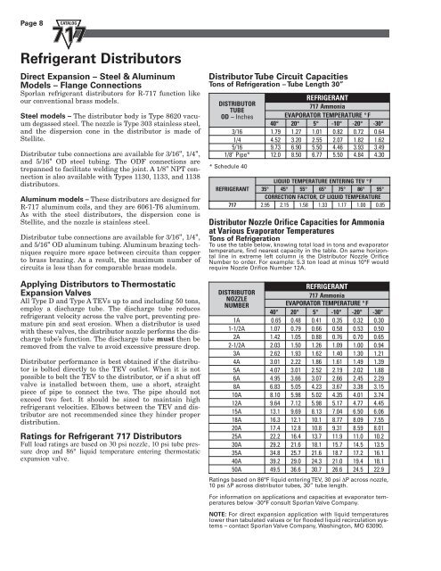
Ratings for Refrigerant 717 Distributors<br />
Full load ratings are based on 30 psi nozzle, 10 psi tube pressure<br />
drop and 86° liquid temperature entering thermostatic<br />
expansion valve.<br />
Distributor Tube Circuit Capacities<br />
Tons of Refrigeration – Tube Length 30”<br />
REFRIGERANT<br />
DISTRIBUTOR<br />
717 Ammonia<br />
T UBE<br />
OD<br />
– Inches<br />
EVAPORATOR<br />
TEMPERATURE ° F<br />
40°<br />
20°<br />
5 ° - 10°<br />
- 20°<br />
-30°<br />
3/16<br />
1.79<br />
1.27<br />
1.01<br />
0.82<br />
0.72<br />
0.64<br />
1/4<br />
4.52<br />
3.20<br />
2.55<br />
2.07<br />
1.82<br />
1.62<br />
5/16<br />
9.73<br />
6.90<br />
5.50<br />
4.46<br />
3.93<br />
3.49<br />
1/8"<br />
Pipe* 12.<br />
0 8.50<br />
6.77<br />
5.50<br />
4.84<br />
4.30<br />
* Schedule 40<br />
LIQUID TEMPERATURE ENTERING TEV ° F<br />
REFRIGERANT 35°<br />
45°<br />
55°<br />
65°<br />
75°<br />
86°<br />
95°<br />
CORRECTION FACTOR, CF LIQUID TEMPERATURE<br />
717<br />
2.95<br />
2.15<br />
1.58<br />
1.33<br />
1.17<br />
1.00<br />
0.85<br />
Distributor Nozzle Orifice Capacities for Ammonia<br />
at Various Evaporator Temperatures<br />
Tons of Refrigeration<br />
To use the table below, knowing total load in tons and evaporator<br />
temperature, find nearest capacity in the table. On same horizontal<br />
line in extreme left column is the Distributor Nozzle Orifice<br />
Number to order. For example: 5.3 ton load at minus 10°F would<br />
require Nozzle Orifice Number 12A.<br />
REFRIGERANT<br />
DISTRIBUTOR<br />
717 Ammonia<br />
NOZZLE<br />
NUMBER<br />
EVAPORATOR TEMPERATURE ° F<br />
40°<br />
20°<br />
5 ° - 10°<br />
- 20°<br />
-30°<br />
1A<br />
0.65<br />
0.48<br />
0.41<br />
0.35<br />
0.32<br />
0.30<br />
1-1/2A<br />
1.07<br />
0.79<br />
0.66<br />
0.58<br />
0.53<br />
0.50<br />
2A<br />
1.42<br />
1.05<br />
0.88<br />
0.76<br />
0.70<br />
0.65<br />
2-1/2A<br />
2.03<br />
1.50<br />
1.26<br />
1.09<br />
1.00<br />
0.94<br />
3A<br />
2.62<br />
1.93<br />
1.62<br />
1.40<br />
1.30<br />
1.21<br />
4A<br />
3.01<br />
2.22<br />
1.86<br />
1.61<br />
1.49<br />
1.39<br />
5A<br />
4.07<br />
3.01<br />
2.52<br />
2.19<br />
2.02<br />
1.88<br />
6A<br />
4.95<br />
3.66<br />
3.07<br />
2.66<br />
2.45<br />
2.29<br />
8A<br />
6.83<br />
5.05<br />
4.23<br />
3.67<br />
3.38<br />
3.15<br />
10A<br />
8.10<br />
5.98<br />
5.02<br />
4.35<br />
4.01<br />
3.74<br />
12A<br />
9.64<br />
7.12<br />
5.98<br />
5.17<br />
4.77<br />
4.45<br />
15A<br />
13.<br />
1 9.69<br />
8.13<br />
7.04<br />
6.50<br />
6.06<br />
18A<br />
16.<br />
3 12.<br />
1 10.<br />
1 8.77<br />
8.09<br />
7.55<br />
20A<br />
17.<br />
4 12.<br />
8 10.<br />
8 9.31<br />
8.59<br />
8.01<br />
25A<br />
22.<br />
2 16.<br />
4 13.<br />
7 11.<br />
9 11.<br />
0 10. 2<br />
30A<br />
29.<br />
2 21.<br />
6 18.<br />
1 15.<br />
7 14.<br />
5 13. 5<br />
35A<br />
34.<br />
8 25.<br />
7 21.<br />
6 18.<br />
7 17.<br />
2 16. 1<br />
40A<br />
39.<br />
2 29.<br />
0 24.<br />
3 21.<br />
0 19.<br />
4 18. 1<br />
50A<br />
49.<br />
5 36.<br />
6 30.<br />
7 26.<br />
6 24.<br />
5 22. 9<br />
Ratings based on 86°F liquid entering TEV, 30 psi ∆P across nozzle,<br />
10 psi ∆P across distributor tubes, 30” tube length.<br />
For information on applications and capacities at evaporator temperatures<br />
below -30°F consult Sporlan Valve Company.<br />
NOTE: For direct expansion application with liquid temperatures<br />
lower than tabulated values or for flooded liquid recirculation systems<br />
– contact Sporlan Valve Company, Washington, MO 63090.