catalog 717.qxd
catalog 717.qxd
catalog 717.qxd

Create successful ePaper yourself
Turn your PDF publications into a flip-book with our unique Google optimized e-Paper software.
Page 18<br />
CATALOG<br />
Design Precautions<br />
Hand Valves<br />
On installations where the valve is isolated from the surge<br />
drum by a hand valve, and a 2 to 3 pound pressure drop from<br />
the valve outlet to the bulb location is likely, we recommend<br />
that an externally equalized valve be used. (See ordering<br />
instructions.)<br />
Oil Return<br />
General – All reciprocating compressors will allow some oil<br />
to pass into the discharge line along with the discharge gas.<br />
Mechanical oil separators are used extensively; however, they<br />
are never completely effective. The untrapped oil passes<br />
through the condenser, liquid line, expansion device and finally<br />
into the evaporator.<br />
In a properly designed direct expansion system, the refrigerant<br />
velocity in the evaporator tubes and in the suction line is<br />
sufficiently high to ensure a continuous return of oil to the<br />
compressor crankcase. But, this is not characteristic of flooded<br />
systems. Here we purposely design the surge drum for a relatively<br />
low vapor velocity to prevent entrainment of liquid<br />
refrigerant droplets and consequent carryover into the suction<br />
line. This design criterion also prevents the return of any oil<br />
from the low side in the normal manner.<br />
reduction in the evaporator heat transfer rate can occur due to<br />
an increase in the refrigerant film resistance. Difficulty in<br />
maintaining the proper liquid level with any type of flooded<br />
control can also be expected.<br />
With a float valve, you can expect the liquid level in the evaporator<br />
to increase with high concentration of oil in a remote<br />
float chamber.<br />
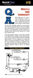
If a Sporlan Level-Master Control is used with the insert bulb<br />
installed in a remote chamber, oil concentration at the bulb can<br />
cause overfeeding with possible floodback. The lower or liquid<br />
balance line must be free of traps and be free draining into<br />
the surge drum or chiller as shown in Figure 4. The oil drain<br />
leg or sump must be located at the lowest point in the low<br />
side.<br />
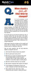
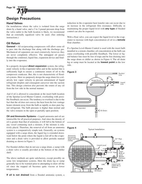
Figure 3<br />
Surge Drum<br />
LMC<br />
Suction<br />
Line<br />
Liquid<br />
Line<br />
And if oil is allowed to concentrate at the insert bulb location<br />
of the Sporlan Level-Master Control, overfeeding with possible<br />
floodback can occur. The tendency to overfeed is due to the<br />
fact that the oil does not convey the heat from the low wattage<br />
heater element away from the bulb as rapidly as does pure liquid<br />
refrigerant. The bulb pressure is higher than normal and<br />
the valve remains in the open or partially open position.<br />
Evaporator<br />
Oil Drain<br />
Oil and Ammonia Systems – Liquid ammonia and oil are<br />
immiscible for all practical purposes. And since the density of<br />
oil is greater than that of ammonia, it will fall to the bottom of<br />
any vessel containing such a mixture, if the mixture is relatively<br />
placid. Therefore, the removal of oil from an ammonia<br />
system is a comparatively simple task. Generally, on systems<br />
equipped with a surge drum, the liquid leg is extended downward<br />
below the point where the liquid is fed off to the evaporator<br />
and a drain valve is provided to allow periodic manual<br />
draining as shown in Figure 3.<br />
For flooded chillers that do not use a surge drum, a sump with<br />
a drain valve is usually provided at the bottom of the chiller<br />
shell.<br />
The above methods are quite satisfactory, except possibly on<br />
some low temperature systems. Here the drain leg or sump<br />
generally has to be warmed prior to attempting to draw off the<br />
oil since the trapped oil becomes quite viscous at lower<br />
temperatures.<br />
Figure 4<br />
Ammonia<br />
Horizontal<br />
Shell and Tube<br />
Chiller<br />
Typical Installation<br />
Liquid Level<br />
2-1/2” Pipe<br />
Shut-off Valve<br />
LMC<br />
Oil Drain<br />
2-1/2” Pipe<br />
1/2” Pipe<br />
Electrical<br />
Connections<br />
Liquid Line<br />
Catch-All or<br />
Strainer<br />
Insert<br />
Bulb of<br />
Level<br />
Master<br />
Element<br />
If oil is not drained from a flooded ammonia system, a